


4RF Aprisa SR+ User Manual
October 2013
Version 1.6.2

| 1
Copyright
Copyright © 2013 4RF Limited. All rights reserved.
This document is protected by copyright belonging to 4RF Limited and may not be reproduced or republished in whole or part in any form without the prior written permission of 4RF Limited.
Trademarks
Aprisa and the 4RF logo are trademarks of 4RF Limited.
Windows is a registered trademark of Microsoft Corporation in the United States and other countries. Java and all Java-related trademarks are trademarks or registered trademarks of Sun Microsystems, Inc. in the United States and other countries. All other marks are the property of their respective owners.
Disclaimer
Although every precaution has been taken preparing this information, 4RF Limited assumes no liability for errors and omissions, or any damages resulting from use of this information. This document or the equipment may change, without notice, in the interests of improving the product.
RoHS and WEEE Compliance
The Aprisa SR is fully compliant with the European Commission’s RoHS (Restriction of Certain Hazardous Substances in Electrical and Electronic Equipment) and WEEE (Waste Electrical and Electronic Equipment) environmental directives.
Restriction of hazardous substances (RoHS)
The RoHS Directive prohibits the sale in the European Union of electronic equipment containing these hazardous substances: lead, cadmium, mercury, hexavalent chromium, polybrominated biphenyls (PBBs), and polybrominated diphenyl ethers (PBDEs).
4RF has worked with its component suppliers to ensure compliance with the RoHS Directive which came into effect on the 1st July 2006.
End-of-life recycling programme (WEEE)
The WEEE Directive concerns the recovery, reuse, and recycling of electronic and electrical equipment. Under the Directive, used equipment must be marked, collected separately, and disposed of properly.
4RF has instigated a programme to manage the reuse, recycling, and recovery of waste in an environmentally safe manner using processes that comply with the WEEE Directive (EU Waste Electrical and Electronic Equipment 2002/96/EC).
4RF invites questions from customers and partners on its environmental programmes and compliance with the European Commission’s Directives (sales@4RF.com).
Aprisa SR User Manual

2 |
Compliance General
The Aprisa SR digital radio predominantly operates within frequency bands that require a site license be issued by the radio regulatory authority with jurisdiction over the territory in which the equipment is being operated.
It is the responsibility of the user, before operating the equipment, to ensure that where required the appropriate license has been granted and all conditions attendant to that license have been met.
Changes or modifications not approved by the party responsible for compliance could void the user’s authority to operate the equipment.
Equipment authorizations sought by 4RF are based on the Aprisa SR radio equipment being installed at a fixed restricted access location and operated in point-to-multipoint or point-to-point mode within the environmental profile defined by EN 300 019, Class 3.4. Operation outside these criteria may invalidate the authorizations and / or license conditions.
The term ‘Radio’ with reference to the Aprisa SR User Manual, is a generic term for one end station of a point-to-multipoint Aprisa SR network and does not confer any rights to connect to any public network or to operate the equipment within any territory.
Compliance European Telecommunications Standards Institute
The Aprisa SR radio is designed to comply with the European Telecommunications Standards Institute (ETSI) specifications as follows:
|
|
12.5 kHz Channel |
|
25 kHz Channel |
|
|
|
|
|
|
|
Radio performance |
|
EN 300 113-2 |
|
EN 302 561 |
|
|
|
|
|
|
|
EMC |
|
EN 301 489 Parts 1 & 5 |
|
||
|
|
|
|
|
|
Environmental |
|
EN 300 019, Class 3.4 |
|
||
|
|
|
|
|
|
Safety |
|
EN 60950-1:2006 |
|
|
|
|
|
|
|
|
|
|
|
|
|
||
Frequency band |
Channel size |
Power input |
Notified |
||
|
|
|
|
|
body |
|
|
|
|
||
136-174 MHz |
12.5 kHz, 25 kHz |
12 VDC |
|
||
|
|
|
|
||
400-470 MHz |
12.5 kHz, 25 kHz |
12 VDC |
|
||
|
|
|
|
|
|
Aprisa SR User Manual

| 3
Compliance Federal Communications Commission
The Aprisa SR radio is designed to comply with the Federal Communications Commission (FCC) specifications as follows:
Radio performance / EMC |
47CFR part 90 Private Land Mobile Radio Services |
||||
|
|
47CFR part 15 Radio Frequency Devices |
|
||
Safety |
|
EN 60950-1:2006 |
|
||
|
|
|
|
|
|
Frequency band |
Channel |
Power |
Authorization |
|
FCC ID |
limits |
size |
input |
|
|
|
|
|
|
|
|
|
406.1 to 454.0 MHz |
12.5 kHz |
12 VDC |
Part 90 Certification |
|
UIPSRN0400012A |
456.0 to 470.0 MHz |
|
|
|
|
|
|
|
|
|
|
|
NOTE: This equipment has been tested and found to comply with the limits for a Class A digital device, pursuant to part 15 of the FCC Rules. These limits are designed to provide reasonable protection against harmful interference when the equipment is operated in a commercial environment. This equipment generates, uses, and can radiate radio frequency energy and, if not installed and used in accordance with the instruction manual, may cause harmful interference to radio communications. Operation of this equipment in a residential area is likely to cause harmful interference in which case the user will be required to correct the interference at his own expense.
Compliance Industry Canada
The Aprisa SR radio is designed to comply with Industry Canada (IC) specifications as follows:
Radio performance |
RSS-GEN |
|
|
||
|
|
RSS-119 |
|
|
|
EMC |
|
This Class A digital apparatus complies with Canadian |
|||
|
|
standard ICES-003. |
|
||
|
|
Cet appareil numérique de la classe A est conforme à |
|||
|
|
la norme NMB-003 du Canada. |
|
||
Safety |
|
EN 60950-1:2006 |
|
||
|
|
|
|
|
|
Frequency band |
Channel |
Power |
|
Authorization |
IC ID |
limits |
size |
input |
|
|
|
|
|
|
|
|
|
406.1 to 430.0 MHz |
12.5 kHz, |
12 VDC |
|
RSS-119 |
6772A-SRN400 |
450.0 to 470.0 MHz |
25 kHz |
|
|
|
|
|
|
|
|
|
|
Aprisa SR User Manual

4 |
Compliance Hazardous Locations Notice
This product is suitable for use in Class 1, Division 2, Groups A - D hazardous locations or non-hazardous locations.
WARNING - EXPLOSION HAZARD - DO NOT REPLACE FUSE UNLESS POWER HAS BEEN SWITCHED OFF OR THE AREA IS KNOWN TO BE NON-HAZARDOUS.
AVERTISSEMENT - RISQUE D'EXPLOSION - COUPER LE COURANT OU S'ASSURER QUE L'EMPLACEMENT EST DESIGNE NON DANGEREUX AVANT DE REPLACER LE FUSIBLE.
WARNING - EXPLOSION HAZARD - DO NOT DISCONNECT EQUIPMENT UNLESS POWER HAS BEEN SWITCHED OFF OR THE AREA IS KNOWN TO BE NON-HAZARDOUS.
AVERTISSEMENT - RISQUE D'EXPLOSION - AVANT DE DECONNECTER L'EQUIPEMENT, COUPER LE COURANT OU S'ASSURER QUE L'EMPLACEMENT EST DESIGNE NON DANGEREUX.
Protection switch remote control connection diagram for hazardous locations.
Aprisa SR User Manual

| 5
RF Exposure Warning
WARNING:
The installer and / or user of Aprisa SR radios shall ensure that a separation distance as given in the following table is maintained between the main axis of the terminal’s antenna and the body of the user or nearby persons.
Minimum separation distances given are based on the maximum values of the following methodologies:
1.Maximum Permissible Exposure non-occupational limit (B or general public) of 47 CFR 1.1310 and the methodology of FCC’s OST/OET Bulletin number 65.
2.Reference levels as given in Annex III, European Directive on the limitation of exposure of the general public to electromagnetic fields (0 Hz to 300 GHz) (1999/519/EC). These distances will ensure indirect compliance with the requirements of EN 50385:2002.
Frequency (MHz) |
Maximum Power |
Maximum Antenna |
Minimum Separation |
|
(dBm) |
Gain (dBi) |
Distance |
|
|
|
(m) |
|
|
|
|
136 |
+ 37 |
15 |
2.5 |
|
|
|
|
174 |
+ 37 |
15 |
2.5 |
|
|
|
|
330 |
+ 37 |
15 |
2.5 |
|
|
|
|
400 |
+ 37 |
15 |
2.5 |
|
|
|
|
470 |
+ 37 |
15 |
2.3 |
|
|
|
|
Aprisa SR User Manual

|
|
Contents | 7 |
Contents |
|
|
1. |
Getting Started ........................................................................ |
13 |
2. |
Introduction............................................................................ |
15 |
|
About This Manual............................................................................... |
15 |
|
What It Covers ............................................................................ |
15 |
|
Who Should Read It ...................................................................... |
15 |
|
Contact Us................................................................................. |
15 |
|
What’s in the Box ............................................................................... |
15 |
|
Aprisa SR Accessory Kit .................................................................. |
16 |
|
Aprisa SR CD Contents ................................................................... |
16 |
|
Software ............................................................................ |
16 |
|
Documentation .................................................................... |
16 |
3. |
About the Radio ....................................................................... |
17 |
|
The 4RF Aprisa SR Radio........................................................................ |
17 |
|
Product Overview ............................................................................... |
18 |
|
Network Coverage and Capacity ....................................................... |
18 |
|
Remote Messaging........................................................................ |
18 |
|
Repeater Messaging ...................................................................... |
19 |
|
Product Features ................................................................................ |
20 |
|
Functions .................................................................................. |
20 |
|
Performance .............................................................................. |
20 |
|
Usability ................................................................................... |
20 |
|
Architecture............................................................................... |
21 |
|
Product Operation................................................................. |
21 |
|
Physical Layer............................................................................. |
21 |
|
Data Link Layer / MAC layer ............................................................ |
21 |
|
Channel Access .................................................................... |
21 |
|
Hop by Hop Transmission......................................................... |
22 |
|
Network Layer ............................................................................ |
23 |
|
Packet Routing..................................................................... |
23 |
|
Security ........................................................................................... |
24 |
|
Interfaces......................................................................................... |
25 |
|
Antenna Interface ........................................................................ |
25 |
|
Ethernet Interface ....................................................................... |
25 |
|
RS-232 Interface .......................................................................... |
25 |
|
USB Interfaces ............................................................................ |
25 |
|
Alarms...................................................................................... |
25 |
|
Front Panel Connections ....................................................................... |
26 |
|
LED Display Panel ............................................................................... |
27 |
|
Normal Operation ........................................................................ |
27 |
|
Single Radio Software Upgrade......................................................... |
27 |
|
Network Software Upgrade ............................................................. |
28 |
|
Test Mode ................................................................................. |
28 |
Aprisa SR User Manual

8 | Contents
4. Product Options ....................................................................... |
29 |
Dual Antenna Port............................................................................... |
29 |
Protected Station ............................................................................... |
30 |
Protected Ports ........................................................................... |
30 |
Operation.................................................................................. |
31 |
Configuration Management ............................................................. |
31 |
Switch Over ............................................................................... |
31 |
Switching Criteria ................................................................. |
32 |
Hardware Manual Lock ........................................................... |
33 |
Remote Control .................................................................... |
33 |
Installation ................................................................................ |
34 |
Mounting ............................................................................ |
34 |
Cabling .............................................................................. |
34 |
Power ............................................................................... |
34 |
Maintenance .............................................................................. |
35 |
Changing the Protected Station IP Addresses ................................. |
35 |
Protected Station Software Upgrade ........................................... |
35 |
Replacing a Protected Station Faulty Radio ................................... |
36 |
Spares ...................................................................................... |
37 |
Replacing a Faulty Protection Switch .......................................... |
37 |
Data Driven Protected Station................................................................. |
38 |
Operation.................................................................................. |
38 |
Switch Over ........................................................................ |
39 |
Configuration Management ...................................................... |
39 |
Installation ................................................................................ |
40 |
Mounting ............................................................................ |
40 |
Cabling .............................................................................. |
41 |
Power ............................................................................... |
41 |
Duplexer Kits..................................................................................... |
42 |
UHF Duplexer Kits ................................................................. |
42 |
VHF Duplexer Kits ................................................................. |
42 |
USB RS-232 Serial Port.......................................................................... |
43 |
USB RS-232 operation ............................................................. |
43 |
Cabling Options .................................................................... |
44 |
USB Retention Clip ................................................................ |
44 |
5. Implementing the Network.......................................................... |
45 |
Network Topologies ............................................................................. |
45 |
Point-To-Point Network .......................................................... |
45 |
Point-to-Multipoint Network ..................................................... |
45 |
Point-to-Multipoint with Repeater 1............................................ |
45 |
Point-to-Multipoint with Repeater 2............................................ |
45 |
Initial Network Deployment ................................................................... |
46 |
Install the Base Station .................................................................. |
46 |
Installing the Remote Stations ......................................................... |
46 |
Install a Repeater Station ............................................................... |
46 |
Network Changes ................................................................................ |
47 |
Adding a Repeater Station .............................................................. |
47 |
Adding a Remote Station ................................................................ |
47 |
Aprisa SR User Manual
|
|
Contents | 9 |
6. |
Preparation ............................................................................ |
49 |
|
Bench Setup...................................................................................... |
49 |
|
Path Planning .................................................................................... |
50 |
|
Antenna Selection and Siting ........................................................... |
50 |
|
Base or Repeater Station ......................................................... |
50 |
|
Remote station .................................................................... |
51 |
|
Antenna Siting ..................................................................... |
52 |
|
Coaxial Feeder Cables ................................................................... |
53 |
|
Linking System Plan ...................................................................... |
53 |
|
Site Requirements............................................................................... |
54 |
|
Power Supply.............................................................................. |
54 |
|
Equipment Cooling ....................................................................... |
54 |
|
Earthing and Lightning Protection ..................................................... |
55 |
|
Feeder Earthing.................................................................... |
55 |
|
Radio Earthing ..................................................................... |
55 |
7. |
Installing the Radio ................................................................... |
56 |
|
Mounting.......................................................................................... |
56 |
|
Required Tools............................................................................ |
56 |
|
DIN Rail Mounting ........................................................................ |
57 |
|
Rack Shelf Mounting ..................................................................... |
58 |
|
Wall Mounting............................................................................. |
58 |
|
Installing the Antenna and Feeder Cable .................................................... |
59 |
|
Connecting the Power Supply ................................................................. |
60 |
|
External Power Supplies................................................................. |
60 |
|
Spare Fuses................................................................................ |
61 |
|
Additional Spare Fuses............................................................ |
62 |
Aprisa SR User Manual

10 |
| Contents |
|
8. |
Managing the Radio ................................................................... |
63 |
|
SuperVisor ........................................................................................ |
63 |
|
Connecting to SuperVisor ............................................................... |
63 |
|
Management PC Connection ..................................................... |
64 |
|
PC Settings for SuperVisor ....................................................... |
65 |
|
Login to SuperVisor................................................................ |
69 |
|
Logout of SuperVisor .............................................................. |
70 |
|
SuperVisor Page Layout........................................................... |
71 |
|
SuperVisor Menu .......................................................................... |
75 |
|
SuperVisor Menu Access .......................................................... |
76 |
|
SuperVisor Menu Items ........................................................... |
77 |
|
Standard Radio............................................................................ |
78 |
|
Terminal ............................................................................ |
78 |
|
Radio ................................................................................ |
90 |
|
Serial .............................................................................. |
102 |
|
Ethernet .......................................................................... |
107 |
|
Networking ....................................................................... |
112 |
|
Security ........................................................................... |
116 |
|
Maintenance ..................................................................... |
131 |
|
Events ............................................................................. |
144 |
|
Software .......................................................................... |
152 |
|
Network Status .................................................................. |
167 |
|
Protected Station ...................................................................... |
174 |
|
Terminal .......................................................................... |
175 |
|
Maintenance ..................................................................... |
190 |
|
Events ............................................................................. |
194 |
|
Software .......................................................................... |
197 |
|
Command Line Interface ..................................................................... |
213 |
|
Connecting to the Management Port ................................................ |
213 |
|
CLI Commands .......................................................................... |
216 |
|
Viewing the CLI Terminal Summary........................................... |
217 |
|
Changing the Radio IP Address with the CLI ................................. |
217 |
|
In-Service Commissioning .................................................................... |
218 |
|
Before You Start............................................................................... |
218 |
|
What You Will Need.................................................................... |
218 |
|
Antenna Alignment............................................................................ |
219 |
|
Aligning the Antennas ................................................................. |
219 |
9. |
Maintenance .......................................................................... |
221 |
|
No User-Serviceable Components ........................................................... |
221 |
|
Radio Software Upgrade...................................................................... |
222 |
|
Network Software Upgrade ........................................................... |
222 |
|
Upgrade Process ................................................................. |
222 |
|
Single Radio Software Upgrade....................................................... |
223 |
|
File Transfer Method............................................................ |
223 |
|
USB Boot Upgrade Method ..................................................... |
224 |
|
Software Downgrade ............................................................ |
225 |
Aprisa SR User Manual

|
|
Contents | 11 |
10. |
Interface Connections............................................................... |
226 |
|
RJ45 Connector Pin Assignments............................................................ |
226 |
|
Ethernet Interface Connections ............................................................. |
226 |
|
RS-232 Serial Interface Connections........................................................ |
227 |
|
Hardware Alarms Connections............................................................... |
227 |
|
Protection Switch Remote Control Connections .......................................... |
227 |
11. Alarm Types and Sources........................................................... |
228 |
|
|
Alarm Types .................................................................................... |
228 |
|
Alarm Events ............................................................................ |
228 |
|
Informational Events................................................................... |
231 |
12. |
Specifications ......................................................................... |
232 |
|
RF Specifications .............................................................................. |
232 |
|
Frequency Bands ....................................................................... |
232 |
|
Channel Sizes ........................................................................... |
232 |
|
Transmitter ............................................................................. |
232 |
|
Receiver ................................................................................. |
233 |
|
Modem ................................................................................... |
233 |
|
Data Payload Security ................................................................. |
233 |
|
Interface Specifications ...................................................................... |
234 |
|
Ethernet Interface ..................................................................... |
234 |
|
RS-232 Asynchronous Interface....................................................... |
235 |
|
Hardware Alarms Interface ........................................................... |
235 |
|
Protection Switch Specifications............................................................ |
235 |
|
Power Specifications.......................................................................... |
236 |
|
Power Supply............................................................................ |
236 |
|
Power Consumption .................................................................... |
236 |
|
Power Dissipation ...................................................................... |
237 |
|
General Specifications........................................................................ |
238 |
|
Environmental .......................................................................... |
238 |
|
Mechanical .............................................................................. |
238 |
|
Compliance.............................................................................. |
238 |
13. Product End Of Life.................................................................. |
239 |
|
|
End-of-Life Recycling Programme (WEEE) ................................................. |
239 |
|
The WEEE Symbol Explained .......................................................... |
239 |
|
WEEE Must Be Collected Separately ................................................. |
239 |
|
YOUR ROLE in the Recovery of WEEE................................................ |
239 |
|
EEE Waste Impacts the Environment and Health .................................. |
239 |
14. |
Abbreviations ......................................................................... |
241 |
15. |
Index ................................................................................... |
242 |
Aprisa SR User Manual

Getting Started | 13
1.Getting Started
This section is an overview of the steps required to commission an Aprisa SR radio network in the field:
Phase 1: |
Pre-installation |
|
|
|
|
|
|
1. |
Confirm path planning. |
Page |
50 |
|
|
|
|
2. |
Ensure that the site preparation is complete: |
Page |
53 |
|
Power requirements |
|
|
|
Tower requirements |
|
|
|
Environmental considerations, for example, temperature control |
|
|
|
Mounting space |
|
|
|
|
|
|
|
|
|
|
Phase 2: |
Installing the radios |
|
|
|
|
|
|
1. |
Mount the radio. |
Page |
56 |
|
|
|
|
2. |
Connect earthing to the radio. |
Page |
55 |
|
|
|
|
3. |
Confirm that the: |
|
|
|
Antenna is mounted and visually aligned |
|
|
|
Feeder cable is connected to the antenna |
|
|
|
Feeder connections are tightened to recommended level |
|
|
|
Tower earthing is complete |
|
|
|
|
|
|
4. |
Install lightning protection. |
Page |
55 |
|
|
|
|
5. |
Connect the coaxial jumper cable between the lightning protection and the |
Page |
59 |
|
radio antenna port. |
|
|
|
|
|
|
6. |
Connect the power to the radio. |
Page |
60 |
|
|
|
|
Aprisa SR User Manual

14 | Getting Started
Phase 3: |
Establishing the link |
|
|
|
|
|
|
1. |
If radio’s IP address is not the default IP address (169.254.50.10 with a subnet |
Page |
213 |
|
mask of 255.255.0.0) and you don’t know the radio’s IP address see ‘Command |
|
|
|
Line Interface’ on page 213. |
|
|
|
|
|
|
2. |
Connect the Ethernet cable between the radio’s Ethernet port and the PC. |
|
|
|
|
|
|
3. |
Confirm that the PC IP settings are correct for the Ethernet connection: |
Page |
65 |
|
IP address |
|
|
|
Subnet mask |
|
|
|
Gateway IP address |
|
|
|
|
|
|
4. |
Open a web browser and login to the radio. |
Page |
69 |
|
|
|
|
5. |
Set or confirm the RF characteristics: |
Page |
92 |
|
TX and RX frequencies |
|
|
|
TX output power |
|
|
|
|
|
|
6. |
Compare the actual RSSI to the expected RSSI value (from your path planning). |
|
|
|
|
|
|
7. |
Align the antennas. |
Page |
219 |
|
|
|
|
8. |
Confirm that the radio is operating correctly; the OK, DATA, CPU and RF LEDs |
|
|
|
are light green (the AUX LED will be off). |
|
|
|
|
|
|
Aprisa SR User Manual

Introduction | 15
2.Introduction
About This Manual
What It Covers
This user manual describes how to install and configure an Aprisa SR point-to-multipoint digital radio network.
It specifically documents an Aprisa SR radio running system software version 1.6.2.
It is recommended that you read the relevant sections of this manual before installing or operating the radios.
Who Should Read It
This manual has been written for professional field technicians and engineers who have an appropriate level of education and experience.
Contact Us
If you experience any difficulty installing or using Aprisa SR after reading this manual, please contact Customer Support or your local 4RF representative.
Our area representative contact details are available from our website:
4RF Limited
26 Glover Street, Ngauranga
PO Box 13-506
Wellington 6032
New Zealand
support@4rf.com |
|
Web site |
www.4rf.com |
Telephone |
+64 4 499 6000 |
Facsimile |
+64 4 473 4447 |
Attention |
Customer Services |
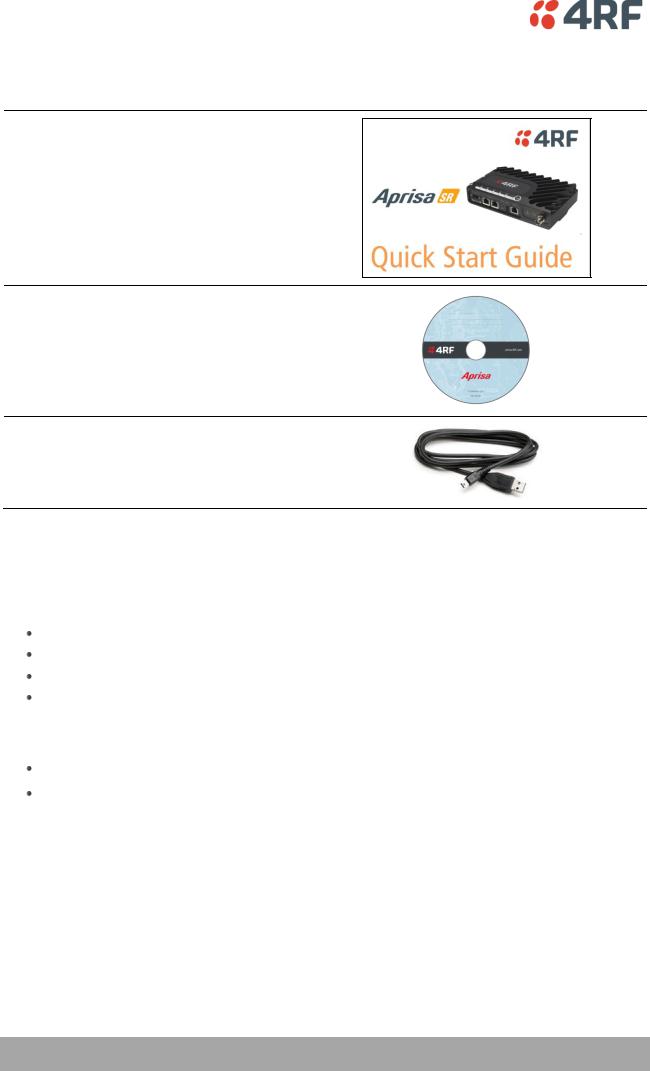
What’s in the Box
Inside the box you will find:
One Aprisa SR radio fitted with a power connector.
One Aprisa SR Accessory kit containing the following:
Aprisa SR CD
Aprisa SR Quick Start Guide
Management Cable
Aprisa SR User Manual
16 | Introduction
Aprisa SR Accessory Kit
The accessory kit contains the following items:
Aprisa SR Quick Start Guide
Aprisa SR CD
Management Cable
USB Cable USB A to USB micro B, 1m
Aprisa SR CD Contents
The Aprisa SR CD contains the following:
Software
The latest version of the radio software (see ‘Radio Software Upgrade’ on page 222) USB Serial Driver
Web browsers - Mozilla Firefox and Internet Explorer are included for your convenience
Adobe™ Acrobat® Reader® which you need to view the PDF files on the Aprisa SR CD
Documentation
User manual - an electronic (PDF) version for you to view online or print
Product collateral - application overviews, product description, quick start guide, case studies, software release notes and white papers
Aprisa SR User Manual

About the Radio | 17
3.About the Radio
The 4RF Aprisa SR Radio
The 4RF Aprisa SR is a point-to-multipoint digital radio providing secure narrowband wireless data connectivity for SCADA, infrastructure and telemetry applications.
The radios carry a combination of serial data and Ethernet data between the base station, repeater stations and remote stations.
A single Aprisa SR is configurable as a point-to-multipoint base station, a remote station or a repeater station.
Aprisa SR User Manual

18 | About the Radio
Product Overview
Network Coverage and Capacity
In a simple point-to-multipoint network, an Aprisa SR, configured as a base station, will communicate with multiple remote units in a given coverage area. With a link range of up to 60 km, a typical deployment will have 30 – 150 remote stations operating to the base station. However, geographic features, such as hills, mountains, trees and foliage, or other path obstructions, such as buildings, tend to limit radio coverage. Additionally, geography may reduce network capacity at the edge of the network where errors may occur and require retransmission. However, the Aprisa SR uses Forward Error Correction (FEC) which greatly improves the sensitivity performance of the radio resulting in less retries and minimal reduction in capacity.
Ultimately, the overall performance of any specific network will be defined by a range of factors including the geographic location, the number of remote stations in the base station coverage area and the traffic profile across the network. Effective network design will distribute the total number of remote stations across the available base stations to ensure optimal geographic coverage and network capacity.
The following are the maximum number of remotes that can operate to a base station for the product configuration:
Configuration |
Maximum Number Of Remotes |
|
|
Non Protected Base Station |
500 |
|
|
Protected Base Station |
150 |
|
|
Remote Messaging
On start-up, the remote station transmits a registration message to the base stations which responds with a registration response. This allows the base station to record the details of all the remote stations active in the network.
If a remote station cannot register with the base station after multiple attempts (RF LED flashing red) within 10 minutes, it will automatically reboot. If a remote station has registered with the base station but then loses communication, it will automatically reboot within 6 minutes.
There are two message types in the Aprisa SR network, broadcast messages and unicast messages. Broadcast messages are transmitted by the base station to the remote stations and unicast messages are transmitted by the remote station to the base station.
All remotes within the coverage area will receive broadcast messages and pass them on to either the Ethernet or serial interface. The RTU determines if the message is intended for it and will accept it or discard it.
Only the base station can receive the unicast messages transmitted from the remote station. Unicast messages are ignored by other remote stations which may be able to receive them.
Aprisa SR User Manual
About the Radio | 19
Repeater Messaging
The Aprisa SR uses a routed protocol throughout the network whereby messages contain source and destination addresses. Upon registration, the radios populate an internal neighbor table to identify the radios in the network. The remote stations will register with a base station, or a repeater, and the repeater registers with a base station. In networks with a repeater, the repeater must register with the base station before the remotes can register with the repeater.
Additionally, all messages contain a ‘message type’ field in the header and messages are designated as either a ‘broadcast’ message, originating from a base station, or a ‘unicast’ message, originating from a remote station.
In a network with a repeater, or multiple repeaters, the base station broadcasts a message which contains a message type, a source address and a destination address. The repeater receives the message and recognizes it is a broadcast message, from the message type and source address and re-broadcasts the message across the network. All remote stations in the coverage area will receive the message but only the radio with the destination address will act upon the message.
Similarly, the remote station will send a unicast message which contains a message type (unicast) a source address and a destination address (the base station). The repeater will receive this message; recognize the message type and source address and forward it to the destination address.
It is this methodology which prevents repeater-repeater loops. If there is repeater (A) which, in some circumstances, is able to pick up the RF signal from another repeater (B), it will not forward the message as it will only forward broadcast messages from the base station (recognized by the source address). For unicast messages the repeater (A) will recognize that the message (from repeater (B)) is not from a remote with which it has an association and similarly ignore the message.
Aprisa SR User Manual

20 | About the Radio
Product Features
Functions
Point-to-Point (PTP) or Point-to-Multipoint (PMP) operation half duplex Licensed frequency bands:
VHF 136-174 MHz
UHF 400-470 MHz
Channel sizes:
12.5 kHz
25 kHz
Typical deployment of 30 remote stations from one base station with a practical limit of a few hundred remote stations
Transparent to all common SCADA protocols; e.g. Modbus, IEC 60870-5-101/104, DNP3 or similar Dual antenna port option for external duplexers or filters (half duplex operation)
Two Ethernet data interfaces plus two RS-232 asynchronous data interfaces Terminal server operation for transporting RS-232 traffic over IP
Data encryption and authentication Layer 2 Ethernet and layer 3 IP filtering SNMPv2 and SNMPv3 support
Radio and user interface redundancy (provided with Aprisa SR Protected Station)
Complies with international standards, including ETSI RF, EMC, safety and environmental standards
Performance
Long distance operation
High transmit power
Low noise receiver
Forward Error Correction
Electronic tuning over the frequency band
Thermal management for high power over a wide temperature range
Usability
Configuration / diagnostics via front panel Management Port USB interface, Ethernet interface
Built-in webserver with full configuration, diagnostics and monitoring functionality, including remote station configuration / diagnostics over the radio link
LED display for on-site diagnostics
Software upgrade and diagnostic reporting via the Host Port USB flash drive Over-the-air software distribution and upgrades
Simple installation with integrated mounting holes for wall, DIN rail and rack shelf mounting
Aprisa SR User Manual

About the Radio | 21
Architecture
Product Operation
There are three components to the wireless interface: the Physical Layer (PHY), the Data Link Layer (DLL) and the Network Layer. These three layers are required to transport data across the wireless channel in the Point-to-Multipoint (PMP) configuration. The Aprisa SR DLL is largely based on the 802.15.4 MAC layer using a proprietary implementation.
Physical Layer
The Aprisa SR PHY uses a one or two frequency ½ duplex transmission mode which eliminates the need for a duplexer. However, a Dual Antenna port option is available for separate transmit and receive antenna connection to support external duplexers or filters (half duplex operation).
Remote nodes are predominantly in receive mode with only sporadic bursts of transmit data. This reduces power consumption.
The Aprisa SR is a packet based radio. Data is sent over the wireless channel in discrete packets / frames, separated in time. The PHY demodulates data within these packets with coherent detection.
The Aprisa SR PHY provides carrier, symbol and frame synchronization predominantly through the use of preambles. This preamble prefixes all packets sent over the wireless channel which enables fast Synchronization.
Data Link Layer / MAC layer
The Aprisa SR PHY enables multiple users to be able to share a single wireless channel; however a DLL is required to manage data transport. The two key components to the DLL are channel access and hop by hop transmission.
Channel Access
The Aprisa SR radio has two modes of channel access, Access Request and Listen Before Send.
Option |
Function |
|
|
Access Request |
Channel access scheme where the base stations controls the |
|
communication on the channel. Remotes ask for access to the |
|
channel, and the base station grants access if the channel is not |
|
occupied. |
|
|
Listen Before Send |
Channel access scheme where network elements listen to ensure |
|
the channel is clear, before trying to access the channel. |
|
|
Aprisa SR User Manual

22 | About the Radio
Access Request
This scheme is particularly suited to digital SCADA systems where all data flows through the base station. In this case it is important that the base station has contention-free access as it is involved in every transaction. The channel access scheme assigns the base station as the channel access arbitrator and therefore inherently it has contention-free access to the channel. This means that there is no possibility of contention on data originating from the base station. As all data flows to or from the base station, this significantly improves the robustness of the system.
All data messages are controlled via the AG (access grant) control message and therefore there is no possibility of contention on the actual end user data. If a remote station accesses the channel, the only contention risk is on the AR (access request) control message. These control messages are designed to be as short as possible and therefore the risk of collision of these control messages is significantly reduced. Should collisions occur these are resolved using a random back off and retry mechanism.
As the base station controls all data transactions multiple applications can be effectively handled, including a mixture of polling and report by exception.
Listen Before Send
The Listen Before Send channel access scheme is realized using Carrier Sense Multiple Access (CSMA). In this mode, a pending transmission requires the channel to be clear. This is determined by monitoring the channel for other signals for a set time prior to transmission. This results in reduced collisions and improved channel capacity.
There are still possibilities for collisions with this technique e.g. if two radios simultaneously determine the channel is clear and transmit at the same time. In this case an acknowledged transaction may be used. The transmitter requests an ACK to ensure that the transmission has been successful. If the transmitter does not receive an ACK, then random backoffs are used to reschedule the next transmission.
Hop by Hop Transmission
Hop by Hop Transmission is realized in the Aprisa SR by adding a MAC address header to the packet. For 802.15.4, there are 2 addresses, the source and destination addresses.
Aprisa SR User Manual

About the Radio | 23
Network Layer
Packet Routing
Packet routing is realized in the Aprisa SR by adding a network address header to the packet. This contains source and destination addresses. For the Network Layer, there are 2 addresses, the address of the originating radio and the address of the terminating radio (i.e. end to end network). This is required for routing packets across multiple hops e.g. PMP with repeaters.
The Aprisa SR uses an automated method for performing address assignment and routing information.
There are two types of packets: unicast and broadcast. Only the base station sends broadcasts which are received by all remote stations. User packets are not interpreted as the radio link is transparent.
Traffic
Data originating on the base station is broadcast to all repeater stations and remote stations
Data originating on a remote station is unicast to the base station only
This can be via multiple repeater stations.
Data originating on a repeater station is unicast to the base station only
Data originating on a base station serial port is terminated on remote station serial ports only
Data originating on a base station Ethernet port is terminated on remote station Ethernet ports or serial ports (Terminal Server mode)
User Traffic
User traffic is prioritized depending on the Serial and Ethernet Data Priority options (see Traffic Settings on ‘Radio > Channel Setup’ on page 97).
If the Serial and Ethernet Data Priority options are equal, then first come first served is invoked.
Repeater stations repeat traffic also on a first come first served basis.
Management Traffic
Management Traffic is prioritized relative to user traffic priority (see Traffic Settings on ‘Radio > Channel Setup’ on page 97).
Aprisa SR User Manual

24 | About the Radio
Security
The Aprisa SR provides security features to implement the key recommendations for industrial control systems. The security provided builds upon the best in class from multiple standards bodies, including:
IEC/TR 62443 (TC65) ‘Industrial Communications Networks – Network and System Security’
IEC/TS 62351 (TC57) ‘Power System Control and Associated Communications – Data and Communication Security’
The security features implemented are:
Data encryption
Counter Mode Encryption (CTR) using Advanced Encryption Standard (AES)
Data authentication
Cipher Block Chaining Message Authentication Code (CBC-MAC) using Advanced Encryption Standard (AES)
Data payload security
CCM |
Counter with CBC-MAC integrity (NIST special publication 800-38C) |
Secured management interface protects configuration Address filtering enables traffic source authorization
Proprietary physical layer protocol and modified MAC layer protocol based on standardized IEEE 802.15.4
Licensed radio spectrum protects against interference
Aprisa SR User Manual

About the Radio | 25
Interfaces
Antenna Interface
Single Antenna Option
1 x TNC, 50 ohm, female connector
Dual Antenna Port Option
2 x TNC, 50 ohm, female connectors
Ethernet Interface
2 x ports 10/100 base-T Ethernet layer 2 switch using RJ45 Used for Ethernet user traffic and product management.
RS-232 Interface
1x RS-232 asynchronous port using RJ45 connector
1x RS-232 asynchronous port using USB host port with USB to RS-232 converter Used for RS-232 asynchronous user traffic only.
USB Interfaces
1 x Management Port using USB micro type B connector
Used for product configuration with the Command Line Interface (CLI). 1 x Host Port using USB standard type A connector
Used for software upgrade and diagnostic reporting.
Alarms
2 x hardware alarm inputs on the power and alarm connector
The alarm states can be transported over the radio link and used to generate SNMP traps.
Aprisa SR User Manual
26 | About the Radio
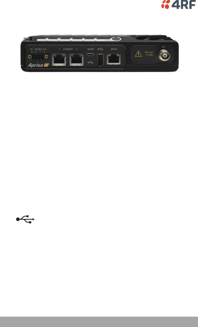
Front Panel Connections
All connections to the radio are made on the front panel. The functions of the connectors are (from left to right):
Designator |
Description |
|
|
A1 / A2 |
The A1, A2 are alarm connections are used in the Protected |
|
Station. |
|
|
10 - 30 VDC; 3A |
+10 to +30 VDC (negative ground) DC power input using |
|
Phoenix Contact 4 pin male screw fitting connector. |
|
AC/DC and DC/DC power supplies are available as accessories. |
|
See ‘External Power Supplies’ on page 60. |
|
|
ETHERNET 1 |
Integrated 10Base-T/100Base-TX layer-2 Ethernet switch using |
|
RJ45 connector. |
|
Used for Ethernet user traffic and product management. |
|
See ‘Ethernet > Port Setup’ on page 108. |
|
|
ETHERNET 2 |
Integrated 10Base-T/100Base-TX layer-2 Ethernet switch using |
|
RJ45 connector. |
|
Used for Ethernet user traffic and product management. |
|
See ‘Ethernet > Port Setup’ on page 108. |
|
|
MGMT |
Management Port using USB micro type B connector. |
|
Used for product configuration with the Command Line |
|
Interface. |
|
See ‘Connecting to the Management Port’ on page 213. |
|
|
|
Host Port using USB standard type A connector. |
|
Used for software upgrade and diagnostic reporting. |
|
See ‘Radio Software Upgrade’ on page 222 and ‘Maintenance > |
|
General’ on page 134. |
|
|
SERIAL |
RS-232 traffic interface using a RJ45 connector. |
|
Used for RS-232 asynchronous user traffic only. |
|
See ‘Serial’ on page 102. |
|
|
ANT |
TNC, 50 ohm, female connector for connection of antenna |
(Antenna connector) |
feeder cable. |
|
|
|
See ‘Coaxial Feeder Cables’ on page 53. |
|
|
Aprisa SR User Manual

About the Radio | 27
LED Display Panel
The Aprisa SR has an LED Display panel which provides on-site alarms / diagnostics without the need for PC.
Normal Operation
In normal radio operation, the LEDs indicate the following conditions:
|
OK |
DATA |
CPU |
RF |
AUX |
|
|
|
|
|
|
Solid |
Alarm present |
|
|
RF path fail |
|
Red |
with severity |
|
|
|
|
|
Critical, Major |
|
|
|
|
|
and Minor |
|
|
|
|
|
|
|
|
|
|
Flashing |
|
|
|
Radio not |
|
Red |
|
|
|
connected to a |
|
|
|
|
|
base station |
|
|
|
|
|
|
|
Solid |
Alarm present |
|
Standby radio |
|
|
Orange |
with Warning |
|
in Protected |
|
|
|
Severity |
|
Station |
|
|
|
|
|
|
|
|
Flashing |
|
Tx Data or Rx |
Device detect |
RF path TX is |
Diagnostics |
Orange |
|
Data on the |
on the USB |
active |
Function |
|
|
USB |
host port |
|
Active |
|
|
management |
|
|
|
|
|
or data port |
|
|
|
|
|
|
|
|
|
Flashing |
|
Tx Data or Rx |
|
RF path RX is |
|
Green |
|
Data on the |
|
active |
|
|
|
serial port |
|
|
|
|
|
|
|
|
|
Solid |
Power on and |
All interface |
Processor Block |
RF path is OK |
|
Green |
functions OK |
ports are OK |
is OK and |
|
|
|
and no alarms |
|
Active radio in |
|
|
|
|
|
Protected |
|
|
|
|
|
Station |
|
|
|
|
|
|
|
|
LED Colour |
Severity |
|
|
Green |
No alarm – information only |
|
|
Orange |
Warning alarm |
|
|
Red |
Critical, major or minor alarm |
|
|
Single Radio Software Upgrade
During a radio software upgrade, the LEDs indicate the following conditions:
Software upgrade started - the OK LED flashes orange
Software upgrade progress indicated by running AUX to DATA LEDs
Software upgrade completed successfully - the OK LED solid orange
Software upgrade failed - any LED flashing red during the upgrade
Aprisa SR User Manual
28 | About the Radio
Network Software Upgrade
During a network software upgrade, the AUX LED flashes orange on the base station and all remote stations.
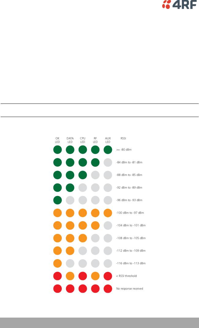
Test Mode
Remote station and repeater station radios have a Test Mode which presents a real time visual display of the RSSI on the LED Display panel. This can be used to adjust the antenna for optimum signal strength (see ‘Maintenance > Test Mode’ on page 137 for Test Mode options).
To enter Test Mode, press and hold the ENTER button on the radio LED panel until all the LEDs flash green (about 3 - 5 seconds). The response time is variable and can be up to 5 seconds.
To exit Test Mode, press and hold the ENTER button until all the LEDs flash red (about 3 – 5 seconds).
The RF LED will be green if the network is operating correctly.
Note: Test Mode traffic has a low priority but could affect customer traffic depending on the relative priorities setup.
The RSSI result is displayed on the LED Display panel as a combination of LED states:
Aprisa SR User Manual
 Loading...