


February 2013
Version 1.5.3a


| 1
Aprisa SR User Manual
Copyright
Copyright © 2013 4RF Limited. All rights reserved.
This document is protected by copyright belonging to 4RF Limited and may not be reproduced or
republished in whole or part in any form without the prior written permission of 4RF Limited.
Trademarks
Aprisa and the 4RF logo are trademarks of 4RF Limited.
Windows is a registered trademark of Microsoft Corporation in the United States and other countries. Java
and all Java-related trademarks are trademarks or registered trademarks of Sun Microsystems, Inc. in the
United States and other countries. All other marks are the property of their respective owners.
Disclaimer
Although every precaution has been taken preparing this information, 4RF Limited assumes no liability for
errors and omissions, or any damages resulting from use of this information. This document or the
equipment may change, without notice, in the interests of improving the product.
RoHS and WEEE Compliance
The Aprisa SR is fully compliant with the European Commission’s RoHS (Restriction of Certain Hazardous
Substances in Electrical and Electronic Equipment) and WEEE (Waste Electrical and Electronic Equipment)
environmental directives.
Restriction of hazardous substances (RoHS)
The RoHS Directive prohibits the sale in the European Union of electronic equipment containing these
hazardous substances: lead, cadmium, mercury, hexavalent chromium, polybrominated biphenyls (PBBs),
and polybrominated diphenyl ethers (PBDEs).
4RF has worked with its component suppliers to ensure compliance with the RoHS Directive which came
into effect on the 1st July 2006.
End-of-life recycling programme (WEEE)
The WEEE Directive concerns the recovery, reuse, and recycling of electronic and electrical equipment.
Under the Directive, used equipment must be marked, collected separately, and disposed of properly.
4RF has instigated a programme to manage the reuse, recycling, and recovery of waste in an
environmentally safe manner using processes that comply with the WEEE Directive (EU Waste Electrical
and Electronic Equipment 2002/96/EC).
4RF invites questions from customers and partners on its environmental programmes and compliance with
the European Commission’s Directives (sales@4RF.com).

2 |
Aprisa SR User Manual
12.5 kHz Channel
25 kHz Channel
Radio performance
EN 300 113-2
EN 302 561
EMC
EN 301 489 Parts 1 & 5
Environmental
EN 300 019, Class 3.4
Safety
EN 60950-1:2006
Frequency band
Channel size
Power input
Notified
body
136-174 MHz
12.5 kHz, 25 kHz
12 VDC
400-470 MHz
12.5 kHz, 25 kHz
12 VDC
Compliance General
The Aprisa SR digital radio predominantly operates within frequency bands that require a site license be
issued by the radio regulatory authority with jurisdiction over the territory in which the equipment is
being operated.
It is the responsibility of the user, before operating the equipment, to ensure that where required the
appropriate license has been granted and all conditions attendant to that license have been met.
Changes or modifications not approved by the party responsible for compliance could void the user’s
authority to operate the equipment.
Equipment authorizations sought by 4RF are based on the Aprisa SR radio equipment being installed at a
fixed location and operated in point-to-multipoint or point-to-point mode within the environmental profile
defined by EN 300 019, Class 3.4. Operation outside these criteria may invalidate the authorizations and /
or license conditions.
The term ‘Radio’ with reference to the Aprisa SR User Manual, is a generic term for one end station of a
point-to-multipoint Aprisa SR network and does not confer any rights to connect to any public network or
to operate the equipment within any territory.
Compliance European Telecommunications Standards Institute
The Aprisa SR radio is designed to comply with the European Telecommunications Standards Institute
(ETSI) specifications as follows:

| 3
Aprisa SR User Manual
Radio performance / EMC
47CFR part 90 Private Land Mobile Radio Services
47CFR part 15 Radio Frequency Devices
Safety
EN 60950-1:2006
Frequency band
limits
Channel
size
Power
input
Authorization
FCC ID
406.1 to 454.0 MHz
456.0 to 470.0 MHz
12.5 kHz
12 VDC
Part 90 Certification
UIPSRN0400012A
Radio performance
RSS-GEN
RSS-119
EMC
This Class A digital apparatus complies with Canadian
standard ICES-003.
Cet appareil numérique de la classe A est conforme à
la norme NMB-003 du Canada.
Safety
EN 60950-1:2006
Frequency band
limits
Channel
size
Power
input
Authorization
IC ID
406.1 to 430.0 MHz
450.0 to 470.0 MHz
12.5 kHz
12 VDC
RSS-119
6772A-SRN400
Compliance Federal Communications Commission
The Aprisa SR radio is designed to comply with the Federal Communications Commission (FCC)
specifications as follows:
NOTE: This equipment has been tested and found to comply with the limits for a Class A digital device,
pursuant to part 15 of the FCC Rules. These limits are designed to provide reasonable protection against
harmful interference when the equipment is operated in a commercial environment. This equipment
generates, uses, and can radiate radio frequency energy and, if not installed and used in accordance with
the instruction manual, may cause harmful interference to radio communications. Operation of this
equipment in a residential area is likely to cause harmful interference in which case the user will be
required to correct the interference at his own expense.
Compliance Industry Canada
The Aprisa SR radio is designed to comply with Industry Canada (IC) specifications as follows:

4 |
Aprisa SR User Manual
WARNING:
The installer and / or user of Aprisa SR radios shall ensure that a separation distance
as given in the following table is maintained between the main axis of the terminal’s
antenna and the body of the user or nearby persons.
Minimum separation distances given are based on the maximum values of the
following methodologies:
1. Maximum Permissible Exposure non-occupational limit (B or general public) of
47 CFR 1.1310 and the methodology of FCC’s OST/OET Bulletin number 65.
2. Reference levels as given in Annex III, European Directive on the limitation of
exposure of the general public to electromagnetic fields (0 Hz to 300 GHz)
(1999/519/EC). These distances will ensure indirect compliance with the
requirements of EN 50385:2002.
Frequency (MHz)
Maximum Power
(dBm)
Maximum Antenna
Gain (dBi)
Minimum Separation
Distance
(m)
136
+ 37
15
2.5
174
+ 37
15
2.5
330
+ 37
15
2.5
400
+ 37
15
2.5
470
+ 37
15
2.3
RF Exposure Warning

Contents | 5
Aprisa SR User Manual
Contents
1. Getting Started .......................................................................... 11
2. Introduction .............................................................................. 13
About This Manual ............................................................................... 13
What It Covers ............................................................................ 13
Who Should Read It ...................................................................... 13
Contact Us ................................................................................. 13
What’s in the Box ............................................................................... 13
Aprisa SR Accessory Kit .................................................................. 14
Aprisa SR CD Contents ................................................................... 14
Software ............................................................................ 14
Documentation .................................................................... 14
3. About the Radio ......................................................................... 15
The 4RF Aprisa SR Radio ........................................................................ 15
Product Overview ............................................................................... 16
Network Coverage and Capacity ....................................................... 16
Remote Messaging ........................................................................ 16
Repeater Messaging ...................................................................... 17
Product Features ................................................................................ 18
Functions .................................................................................. 18
Performance .............................................................................. 18
Usability ................................................................................... 18
Architecture ............................................................................... 19
Product Operation ................................................................. 19
Physical Layer ............................................................................. 19
Data Link Layer / MAC layer ............................................................ 19
Channel Access .................................................................... 19
Hop by Hop Transmission ......................................................... 20
Network Layer ............................................................................ 21
Packet Routing ..................................................................... 21
Security ........................................................................................... 22
Interfaces ......................................................................................... 23
Antenna Interface ........................................................................ 23
Ethernet Interface ....................................................................... 23
RS-232 Interface .......................................................................... 23
USB Interfaces ............................................................................ 23
Front Panel Connections ....................................................................... 24
LED Display Panel ............................................................................... 25
Normal Operation ........................................................................ 25
Single Radio Software Upgrade ......................................................... 25
Network Software Upgrade ............................................................. 26
Test Mode ................................................................................. 26

6 | Contents
Aprisa SR User Manual
4. Product Options ......................................................................... 27
Dual Antenna Port ............................................................................... 27
Protected Station ............................................................................... 28
Operation .................................................................................. 28
Configuration Management ............................................................. 29
Switch Over ............................................................................... 29
Switching Criteria ................................................................. 29
Hardware Manual Lock............................................................ 30
Remote Control .................................................................... 30
Installation ................................................................................ 31
Mounting ............................................................................ 31
Cabling .............................................................................. 31
Power ............................................................................... 31
Maintenance .............................................................................. 32
Changing the Protected Station IP Addresses ................................. 32
Protected Station Software Upgrade ........................................... 32
Replacing a Protected Station Faulty Radio ................................... 33
Spares ...................................................................................... 34
Replacing a Faulty Protection Switch .......................................... 34
Data Driven Protected Station................................................................. 35
Operation .................................................................................. 35
Switch Over ........................................................................ 36
Configuration Management ...................................................... 36
Installation ................................................................................ 37
Mounting ............................................................................ 37
Cabling .............................................................................. 38
Power ............................................................................... 38
Duplexer Kit ...................................................................................... 39
USB RS-232 Serial Port .......................................................................... 40
USB RS-232 operation ............................................................. 40
Cabling Options .................................................................... 40
5. Implementing the Network ........................................................... 41
Network Topologies ............................................................................. 41
Point-To-Point Network .......................................................... 41
Point-to-Multipoint Network ..................................................... 41
Point-to-Multipoint with Repeater 1 ............................................ 41
Point-to-Multipoint with Repeater 2 ............................................ 41
Initial Network Deployment ................................................................... 42
Install the Base Station .................................................................. 42
Installing the Remote Stations ......................................................... 42
Install a Repeater Station ............................................................... 42
Network Changes ................................................................................ 43
Adding a Repeater Station .............................................................. 43
Adding a Remote Station ................................................................ 43

Contents | 7
Aprisa SR User Manual
6. Preparation............................................................................... 45
Bench Setup ...................................................................................... 45
Path Planning .................................................................................... 46
Antenna Selection and Siting ........................................................... 46
Base or Repeater Station ......................................................... 46
Remote station .................................................................... 47
Antenna Siting ..................................................................... 48
Coaxial Feeder Cables ................................................................... 49
Linking System Plan ...................................................................... 49
Site Requirements ............................................................................... 50
Power Supply .............................................................................. 50
Equipment Cooling ....................................................................... 50
Earthing and Lightning Protection ..................................................... 51
Feeder Earthing .................................................................... 51
Radio Earthing ..................................................................... 51
7. Installing the Radio ..................................................................... 52
Mounting .......................................................................................... 52
Required Tools ............................................................................ 52
DIN Rail Mounting ........................................................................ 53
Rack Shelf Mounting ..................................................................... 54
Wall Mounting ............................................................................. 54
Installing the Antenna and Feeder Cable .................................................... 55
Connecting the Power Supply ................................................................. 56
External Power Supplies ................................................................. 56
Spare Fuses ................................................................................ 57
Additional Spare Fuses ............................................................ 58

8 | Contents
Aprisa SR User Manual
8. Managing the Radio ..................................................................... 59
SuperVisor ........................................................................................ 59
Connecting to SuperVisor ............................................................... 59
Management PC Connection ..................................................... 60
PC Settings for SuperVisor ....................................................... 61
Login to SuperVisor................................................................ 65
Logout of SuperVisor .............................................................. 66
SuperVisor Page Layout ........................................................... 67
SuperVisor Menu .......................................................................... 71
SuperVisor Menu Access .......................................................... 72
SuperVisor Menu Items............................................................ 73
Standard Radio............................................................................ 74
Terminal ............................................................................ 74
Radio ................................................................................ 84
Serial ................................................................................ 94
Ethernet .......................................................................... 100
Security ........................................................................... 108
Maintenance...................................................................... 122
Events ............................................................................. 135
Software .......................................................................... 142
Network Status .................................................................. 158
Protected Station....................................................................... 165
Terminal .......................................................................... 166
Maintenance...................................................................... 179
Events ............................................................................. 183
Software .......................................................................... 186
Command Line Interface ..................................................................... 202
Connecting to the Management Port ................................................ 202
CLI Commands .......................................................................... 205
Viewing the CLI Terminal Summary ........................................... 206
Changing the Radio IP Address with the CLI ................................. 206
In-Service Commissioning .................................................................... 207
Before You Start ............................................................................... 207
What You Will Need .................................................................... 207
Antenna Alignment ............................................................................ 208
Aligning the Antennas ................................................................. 208
9. Maintenance ............................................................................ 209
No User-Serviceable Components ........................................................... 209
Radio Software Upgrade ...................................................................... 210
Network Software Upgrade ........................................................... 210
Upgrade Process ................................................................. 210
Single Radio Software Upgrade ....................................................... 211
File Transfer Method ............................................................ 211
USB Boot Upgrade Method ..................................................... 212
Software Downgrade ............................................................ 213

Contents | 9
Aprisa SR User Manual
10. Interface Connections ................................................................ 214
RJ45 Connector Pin Assignments ............................................................ 214
Ethernet Interface Connections ............................................................. 214
RS-232 Serial Interface Connections ........................................................ 215
Protection Switch Remote Control Connections .......................................... 215
11. Alarm Types and Sources ............................................................ 216
Alarm Types .................................................................................... 216
Alarm Events ............................................................................ 216
Informational Events ................................................................... 219
12. Specifications ........................................................................... 220
RF Specifications .............................................................................. 220
ETSI Compliant .......................................................................... 220
Frequency Bands ................................................................ 220
Channel Sizes .................................................................... 220
Product Range ................................................................... 220
Transmitter ....................................................................... 221
Receiver .......................................................................... 221
Modem ............................................................................ 222
Data Payload Security .......................................................... 222
Interface Specifications ...................................................................... 223
Ethernet Interface ..................................................................... 223
RS-232 Asynchronous Interface ....................................................... 224
Protection Switch Specifications ............................................................ 224
Power Specifications .......................................................................... 225
Power Supply ............................................................................ 225
Power Consumption .................................................................... 225
Power Dissipation ...................................................................... 226
General Specifications ........................................................................ 227
Environmental .......................................................................... 227
Mechanical .............................................................................. 227
Compliance .............................................................................. 227
13. Product End Of Life ................................................................... 228
End-of-Life Recycling Programme (WEEE) ................................................. 228
The WEEE Symbol Explained .......................................................... 228
WEEE Must Be Collected Separately ................................................. 228
YOUR ROLE in the Recovery of WEEE ................................................ 228
EEE Waste Impacts the Environment and Health .................................. 228
14. Abbreviations ........................................................................... 229
15. Index ...................................................................................... 230


Getting Started | 11
Aprisa SR User Manual
Phase 1:
Pre-installation
1.
Confirm path planning.
Page 46
2.
Ensure that the site preparation is complete:
Power requirements
Tower requirements
Environmental considerations, for example, temperature control
Mounting space
Page 49
Phase 2:
Installing the radios
1.
Mount the radio.
Page 52
2.
Connect earthing to the radio.
Page 51
3.
Confirm that the:
Antenna is mounted and visually aligned
Feeder cable is connected to the antenna
Feeder connections are tightened to recommended level
Tower earthing is complete
4.
Install lightning protection.
Page 51
5.
Connect the coaxial jumper cable between the lightning protection and the
radio antenna port.
Page 55
6.
Connect the power to the radio.
Page 56
1. Getting Started
This section is an overview of the steps required to commission an Aprisa SR radio network in the field:

12 | Getting Started
Aprisa SR User Manual
Phase 3:
Establishing the link
1.
If radio’s IP address is not the default IP address (169.254.50.10 with a subnet
mask of 255.255.0.0) and you don’t know the radio’s IP address see ‘Command
Line Interface’ on page 202.
Page 202
2.
Connect the Ethernet cable between the radio’s Ethernet port and the PC.
3.
Confirm that the PC IP settings are correct for the Ethernet connection:
IP address
Subnet mask
Gateway IP address
Page 61
4.
Open a web browser and login to the radio.
Page 65
5.
Set or confirm the RF characteristics:
TX and RX frequencies
TX output power
Page 85
6.
Compare the actual RSSI to the expected RSSI value (from your path planning).
7.
Align the antennas.
Page 208
8.
Confirm that the radio is operating correctly; the OK, DATA, CPU and RF LEDs
are light green (the AUX LED will be off).

Introduction | 13
Aprisa SR User Manual
4RF Limited
26 Glover Street, Ngauranga
PO Box 13-506
Wellington 6032
New Zealand
E-mail
support@4rf.com
Web site
www.4rf.com
Telephone
+64 4 499 6000
Facsimile
+64 4 473 4447
Attention
Customer Services
2. Introduction
About This Manual
What It Covers
This user manual describes how to install and configure an Aprisa SR point-to-multipoint digital radio
network.
It specifically documents an Aprisa SR radio running system software version 1.5.3.
It is recommended that you read the relevant sections of this manual before installing or operating the
radios.
Who Should Read It
This manual has been written for professional field technicians and engineers who have an appropriate
level of education and experience.
Contact Us
If you experience any difficulty installing or using Aprisa SR after reading this manual, please contact
Customer Support or your local 4RF representative.
Our area representative contact details are available from our website:
What’s in the Box
Inside the box you will find:
One Aprisa SR radio fitted with a power connector.
One Aprisa SR Accessory kit containing the following:
Aprisa SR CD
Aprisa SR Quick Start Guide
Management Cable

14 | Introduction
Aprisa SR User Manual
Aprisa SR Quick Start Guide
Aprisa SR CD
Management Cable
USB Cable USB A to USB micro B, 1m
Aprisa SR Accessory Kit
The accessory kit contains the following items:
Aprisa SR CD Contents
The Aprisa SR CD contains the following:
Software
The latest version of the radio software (see ‘Radio Software Upgrade’ on page 210)
USB Serial Driver
Web browsers - Mozilla Firefox and Internet Explorer are included for your convenience
Adobe™ Acrobat® Reader® which you need to view the PDF files on the Aprisa SR CD
Documentation
User manual - an electronic (PDF) version for you to view online or print
Product collateral - application overviews, product description, quick start guide, case studies,
software release notes and white papers

About the Radio | 15
Aprisa SR User Manual
3. About the Radio
The 4RF Aprisa SR Radio
The 4RF Aprisa SR is a point-to-multipoint digital radio providing secure narrowband wireless data
connectivity for SCADA, infrastructure and telemetry applications.
The radios carry a combination of serial data and Ethernet data between the base station, repeater
stations and remote stations.
A single Aprisa SR is configurable as a point-to-multipoint base station, a remote station or a repeater
station.

16 | About the Radio
Aprisa SR User Manual
Product Overview
Network Coverage and Capacity
In a simple point-to-multipoint network, an Aprisa SR, configured as a base station, will communicate with
multiple remote units in a given coverage area. With a link range of up to 60 km a typical deployment will
have 30 – 50 remote stations attached to the base station. However, geographic features, such as hills,
mountains, trees and foliage, or other path obstructions, such as buildings, tend to limit radio coverage.
Additionally, geography may reduce network capacity at the edge of the network where errors may occur
and require retransmission. However, the Aprisa SR uses Forward Error Correction (FEC) which greatly
improves the sensitivity performance of the radio resulting in less retries and minimal reduction in
capacity.
Ultimately, the overall performance of any specific network will be defined by a range of factors including
the geographic location, the number of remote stations in the base station coverage area and the traffic
profile across the network. Effective network design will distribute the total number of remote stations
across the available base stations to ensure optimal geographic coverage and network capacity.
Remote Messaging
On start-up, the remote station transmits a registration message to the base stations which responds with
a registration response. This allows the base station to record the details of all the remote stations active
in the network.
If a remote station cannot register with the base station after multiple attempts (RF LED flashing red)
within 10 minutes, it will automatically reboot. If a remote station has registered with the base station
but then loses communication, it will automatically reboot within 6 minutes.
There are two message types in the Aprisa SR network, broadcast messages and unicast messages.
Broadcast messages are transmitted by the base station to the remote stations and unicast messages are
transmitted by the remote station to the base station.
All remotes within the coverage area will receive broadcast messages and pass them on to either the
Ethernet or serial interface. The RTU determines if the message is intended for it and will accept it or
discard it.
Only the base station can receive the unicast messages transmitted from the remote station. Unicast
messages are ignored by other remote stations which may be able to receive them.

About the Radio | 17
Aprisa SR User Manual
Repeater Messaging
The Aprisa SR uses a routed protocol throughout the network whereby messages contain source and
destination addresses. Upon registration, the radios populate an internal neighbor table to identify the
radios in the network. The remote stations will register with a base station, or a repeater, and the
repeater registers with a base station. In networks with a repeater, the repeater must register with the
base station before the remotes can register with the repeater.
Additionally, all messages contain a ‘message type’ field in the header and messages are designated as
either a ‘broadcast’ message, originating from a base station, or a ‘unicast’ message, originating from a
remote station.
In a network with a repeater, or multiple repeaters, the base station broadcasts a message which contains
a message type, a source address and a destination address. The repeater receives the message and
recognizes it is a broadcast message, from the message type and source address and re-broadcasts the
message across the network. All remote stations in the coverage area will receive the message but only
the radio with the destination address will act upon the message.
Similarly, the remote station will send a unicast message which contains a message type (unicast) a source
address and a destination address (the base station). The repeater will receive this message; recognize
the message type and source address and forward it to the destination address.
It is this methodology which prevents repeater-repeater loops. If there is repeater (A) which, in some
circumstances, is able to pick up the RF signal from another repeater (B), it will not forward the message
as it will only forward broadcast messages from the base station (recognized by the source address). For
unicast messages the repeater (A) will recognize that the message (from repeater (B)) is not from a
remote with which it has an association and similarly ignore the message.

18 | About the Radio
Aprisa SR User Manual
Product Features
Functions
Point-to-Point (PTP) or Point-to-Multipoint (PMP) operation half duplex
Licensed frequency bands:
VHF 136-174 MHz
UHF 400-470 MHz
Channel sizes:
12.5 kHz
25 kHz
Typical deployment of 30 remote stations from one base station with a practical limit of a few
hundred remote stations
Dual antenna port option for external duplexers or filters (half duplex operation)
Two Ethernet data interfaces plus two RS-232 asynchronous data interfaces
Terminal server operation for transporting RS-232 traffic over IP
Data encryption and authentication
Radio and user interface redundancy (provided with Aprisa SR Protected Station)
Complies with international standards, including ETSI RF, EMC, safety and environmental standards
Performance
Long distance operation
High transmit power
Low noise receiver
Forward Error Correction
Electronic tuning over the frequency band
Thermal management for high power over a wide temperature range
Usability
Configuration / diagnostics via front panel Management Port USB interface, Ethernet interface
Built-in webserver with full configuration, diagnostics and monitoring functionality, including
remote station configuration / diagnostics over the radio link
LED display for on-site diagnostics
Software upgrade and diagnostic reporting via the Host Port USB flash drive
Over-the-air software distribution and upgrades
Simple installation with integrated mounting holes for wall, DIN rail and rack shelf mounting

About the Radio | 19
Aprisa SR User Manual
Access Mode
Function
Access Request
Channel access scheme where the base stations controls the
communication on the channel. Remotes ask for access to the
channel, and the base station grants access if the channel is not
occupied.
Listen Before Send
Channel access scheme where network elements listen to ensure
the channel is clear, before trying to access the channel.
Architecture
Product Operation
There are three components to the wireless interface: the Physical Layer (PHY), the Data Link Layer (DLL)
and the Network Layer. These three layers are required to transport data across the wireless channel in
the Point-to-Multipoint (PMP) configuration. The Aprisa SR DLL is largely based on the 802.15.4 MAC layer
using a proprietary implementation.
Physical Layer
The Aprisa SR PHY uses a one or two frequency ½ duplex transmission mode which eliminates the need for
a duplexer. However, a Dual Antenna port option is available for separate transmit and receive antenna
connection to support external duplexers or filters (half duplex operation).
Remote nodes are predominantly in receive mode with only sporadic bursts of transmit data. This reduces
power consumption.
The Aprisa SR is a packet based radio. Data is sent over the wireless channel in discrete packets / frames,
separated in time. The PHY demodulates data within these packets with coherent detection.
The Aprisa SR PHY provides carrier, symbol and frame synchronisation predominantly through the use of
preambles. This preamble prefixes all packets sent over the wireless channel which enables fast
synchronisation.
Data Link Layer / MAC layer
The Aprisa SR PHY enables multiple users to be able to share a single wireless channel; however a DLL is
required to manage data transport. The two key components to the DLL are channel access and hop by
hop transmission.
Channel Access
The Aprisa SR radio has two modes of channel access, Access Request and Listen Before Send.

20 | About the Radio
Aprisa SR User Manual
Access Request
This scheme is particularly suited to digital SCADA systems where all data flows through the base station.
In this case it is important that the base station has contention-free access as it is involved in every
transaction. The channel access scheme assigns the base station as the channel access arbitrator and
therefore inherently it has contention-free access to the channel. This means that there is no possibility
of contention on data originating from the base station. As all data flows to or from the base station, this
significantly improves the robustness of the system.
All data messages are controlled via the AG (access grant) control message and therefore there is no
possibility of contention on the actual end user data. If a remote station accesses the channel, the only
contention risk is on the AR (access request) control message. These control messages are designed to be
as short as possible and therefore the risk of collision of these control messages is significantly reduced.
Should collisions occur these are resolved using a random back off and retry mechanism.
As the base station controls all data transactions multiple applications can be effectively handled,
including a mixture of polling and report by exception.
Listen Before Send
The Listen Before Send channel access scheme is realized using Carrier Sense Multiple Access (CSMA). In
this mode, a pending transmission requires the channel to be clear. This is determined by monitoring the
channel for other signals for a set time prior to transmission. This results in reduced collisions and
improved channel capacity.
There are still possibilities for collisions with this technique e.g. if two radios simultaneously determine
the channel is clear and transmit at the same time. In this case an acknowledged transaction may be used.
The transmitter requests an ACK to ensure that the transmission has been successful. If the transmitter
does not receive an ACK, then random backoffs are used to reschedule the next transmission.
Hop by Hop Transmission
Hop by Hop Transmission is realized in the Aprisa SR by adding a MAC address header to the packet. For
802.15.4, there are 2 addresses, the source and destination addresses.

About the Radio | 21
Aprisa SR User Manual
Network Layer
Packet Routing
Packet routing is realized in the Aprisa SR by adding a network address header to the packet. This contains
source and destination addresses. For the Network Layer, there are 2 addresses, the address of the
originating radio and the address of the terminating radio (i.e. end to end network). This is required for
routing packets across multiple hops e.g. PMP with repeaters.
The Aprisa SR uses an automated method for performing address assignment and routing information.
There are two types of packets: unicast and broadcast. Only the base station sends broadcasts which are
received by all remote stations. User packets are not interpreted as the radio link is transparent.
Traffic
Data originating on the base station is broadcast to all repeater stations and remote stations
Data originating on a remote station is unicast to the base station only
This can be via multiple repeater stations.
Data originating on a repeater station is unicast to the base station only
Data originating on a base station serial port is terminated on remote station serial ports only
Data originating on a base station Ethernet port is terminated on remote station Ethernet ports or
serial ports (Terminal Server mode)
User Traffic
User traffic is prioritized depending on the Serial and Ethernet Data Priority options (see ‘Serial >
Advanced’ on page 99 and ‘Ethernet > Advanced’ on page 106).
If the Serial and Ethernet Data Priority options are equal, then first come first served is invoked.
Repeater stations repeat traffic also on a first come first served basis.
Management Traffic
Ethernet Management Traffic is also prioritized relative to user traffic (see ‘Ethernet > Advanced’ on page
106).

22 | About the Radio
Aprisa SR User Manual
Security
The Aprisa SR provides security features to implement the key recommendations for industrial control
systems. The security provided builds upon the best in class from multiple standards bodies, including:
IEC/TR 62443 (TC65) ‘Industrial Communications Networks – Network and System Security’
IEC/TS 62351 (TC57) ‘Power System Control and Associated Communications – Data and
Communication Security’
The security features implemented are:
Data encryption
Counter Mode Encryption (CTR) using Advanced Encryption Standard (AES)
Data authentication
Cipher Block Chaining Message Authentication Code (CBC-MAC) using Advanced Encryption
Standard (AES)
Data payload security
CCM Counter with CBC-MAC integrity (NIST special publication 800-38C)
Secured management interface protects configuration
Address filtering enables traffic source authorization
Proprietary physical layer protocol and modified MAC layer protocol based on standardized IEEE
802.15.4
Licensed radio spectrum protects against interference

About the Radio | 23
Aprisa SR User Manual
Interfaces
Antenna Interface
Single Antenna Option
1 x TNC, 50 ohm, female connector
Dual Antenna Port Option
2 x TNC, 50 ohm, female connectors
Ethernet Interface
2 x ports 10/100 base-T Ethernet layer 2 switch using RJ45
Used for Ethernet user traffic and product management.
RS-232 Interface
1x RS-232 asynchronous port using RJ45 connector
1x RS-232 asynchronous port using USB host port with USB to RS-232 converter
Used for RS-232 asynchronous user traffic only.
USB Interfaces
1 x Management Port using USB micro type B connector
Used for product configuration with the Command Line Interface (CLI).
1 x Host Port using USB standard type A connector
Used for software upgrade and diagnostic reporting.

24 | About the Radio
Aprisa SR User Manual
Designator
Description
A1 / A2
The A1, A2 are alarm connections are used in the Protected
Station.
10 - 30 VDC; 3A
+10 to +30 VDC (negative ground) DC power input using
Phoenix Contact 4 pin male screw fitting connector.
AC/DC and DC/DC power supplies are available as accessories.
See ‘External Power Supplies’ on page 56.
ETHERNET 1
Integrated 10Base-T/100Base-TX layer-2 Ethernet switch using
RJ45 connector.
Used for Ethernet user traffic and product management.
See ‘Ethernet > Port Setup’ on page 101.
ETHERNET 2
Integrated 10Base-T/100Base-TX layer-2 Ethernet switch using
RJ45 connector.
Used for Ethernet user traffic and product management.
See ‘Ethernet > Port Setup’ on page 101.
MGMT
Management Port using USB micro type B connector.
Used for product configuration with the Command Line
Interface.
See ‘Connecting to the Management Port’ on page 202.
Host Port using USB standard type A connector.
Used for software upgrade and diagnostic reporting.
See ‘Radio Software Upgrade’ on page 210 and ‘Maintenance >
General’ on page 125.
SERIAL
RS-232 traffic interface using a RJ45 connector.
Used for RS-232 asynchronous user traffic only.
See ‘Serial’ on page 94.
ANT
(Antenna connector)
TNC, 50 ohm, female connector for connection of antenna
feeder cable.
See ‘Coaxial Feeder Cables’ on page 49.
Front Panel Connections
All connections to the radio are made on the front panel. The functions of the connectors are (from left to
right):

About the Radio | 25
Aprisa SR User Manual
OK
DATA
CPU
RF
AUX
Solid
Red
Alarm present
with severity
Critical, Major
and Minor
RF path fail
Flashing
Red
Radio not
connected to a
base station
Solid
Orange
Alarm present
with Warning
Severity
Standby radio
in Protected
Station
Flashing
Orange
Tx Data or Rx
Data on the
USB
management
or data port
Device detect
on the USB
host port
RF path TX is
active
Diagnostics
Function
Active
Flashing
Green
Tx Data or Rx
Data on the
serial port
RF path RX is
active
Solid
Green
Power on and
functions OK
and no alarms
All interface
ports are OK
Processor Block
is OK and
Active radio in
Protected
Station
RF path is OK
LED Colour
Severity
Green
No alarm – information only
Orange
Warning alarm
Red
Critical, major or minor alarm
LED Display Panel
The Aprisa SR has an LED Display panel which provides on-site alarms / diagnostics without the need for
PC.
Normal Operation
In normal radio operation, the LEDs indicate the following conditions:
Single Radio Software Upgrade
During a radio software upgrade, the LEDs indicate the following conditions:
Software upgrade started - the OK LED flashes orange
Software upgrade progress indicated by running AUX to DATA LEDs
Software upgrade completed successfully - the OK LED solid orange
Software upgrade failed - any LED flashing red during the upgrade

26 | About the Radio
Aprisa SR User Manual
Network Software Upgrade
During a network software upgrade, the AUX LED flashes orange on the base station and all remote
stations.
Test Mode
Remote station and repeater station radios have a Test Mode which presents a real time visual display of
the RSSI on the LED Display panel. This can be used to adjust the antenna for optimum signal strength (see
‘Maintenance > Test Mode’ on page 128 for Test Mode options).
To enter Test Mode, press and hold the ENTER button on the radio LED panel until all the LEDs flash green
(about 3 - 5 seconds). The response time is variable and can be up to 5 seconds.
To exit Test Mode, press and hold the ENTER button until all the LEDs flash red (about 3 – 5 seconds).
The RF LED will be green if the network is operating correctly.
Note: Test Mode traffic has a low priority but could affect customer traffic depending on the relative
priorities setup.
The RSSI result is displayed on the LED Display panel as a combination of LED states:

Product Options | 27
Aprisa SR User Manual
Part Number
Part Description
APSR-N400-012-DO-12-ETAA
4RF SR, BR, 400-470 MHz, 12.5 kHz, DO, 12 VDC, ET, AA
4. Product Options
Dual Antenna Port
The standard Aprisa SR uses a one or two frequency ½ duplex transmission mode which eliminates the
need for a duplexer. However, a dual antenna port option is available for separate transmit and receive
antenna connection to support external duplexers or filters. The transmission remains half duplex.
Example Part:

28 | Product Options
Aprisa SR User Manual
Part Number
Part Description
APSR-R400-012-SO-12-ETAA
4RF SR, PS, 400-470 MHz, 12.5 kHz, SO, 12 VDC, ET, AA
Protected Station
The Aprisa SR Protected Station provides radio and user interface protection for Aprisa SR radios. The RF
ports and interface ports from two standard Aprisa SR Radios are switched to the standby radio if there is
a failure in the active radio.
Example Part:
The Aprisa SR Protected Station is comprised of an Aprisa SR Protection Switch and two standard Aprisa SR
radios. This configuration provides the ability to ‘hot-swap’ a failed radio without interrupting user traffic
on the active radio. Additionally, retains the full temperature range specification of a single radio.
The Aprisa SR radios can be any of the currently available Aprisa SR radio frequency bands, channel sizes
or single / dual antenna port options.
By default, the Aprisa SR Protected Station is configured with the left hand radio (A) designated as the
primary radio and the right hand radio (B) designated as the secondary radio. Each radio is configured with
its own unique IP and MAC address and the address of the partner radio.
On power-up, the primary radio will assume the active role and the secondary radio will assume the
standby role. If, for some reason, only one radio is powered on it will automatically assume the active
role.
Operation
In normal operation, the active radio carries all RS-232 serial and Ethernet traffic over the radio link and
the standby radio is unused with its transmitter turned off. Both radios are continually monitored for
correct operation and alarms are raised if an event occurs.
Both the active and standby radios send regular ‘keep alive’ messages to each other to indicate if they are
operating correctly. In the event of a failure on the active radio, the RF link and user interface traffic is
automatically switched to the standby radio.
The failed radio can then be replaced in the field without interrupting user traffic (see ‘Replacing a
Protected Station Faulty Radio’ on page 33).

Product Options | 29
Aprisa SR User Manual
PA current
Tx AGC
Tx reverse power
Thermal shutdown
Temperature threshold
Thermal shutdown
RSSI Threshold
RX Synthesizer Not Locked
Rx CRC errors
RF no receive data
Ethernet port 1 – no receive data
Ethernet port 2 – no receive data
Ethernet port 1 - data receive errors
Ethernet port 2 – data receive errors
Ethernet port 1 – data transmit errors
Ethernet port 2 - data transmit errors
Serial port – no receive data
Serial port – data receive errors
Component failure
Calibration failure
Configuration not supported
Protection Hardware Failure
Configuration Management
The Primary and Secondary radios are managed with the embedded web-based management tool,
SuperVisor (see ‘Managing the Radio’ on page 59) by using either the Primary or Secondary IP address.
Configuration changes in one of the radios will automatically be reflected in the partner radio.
To ensure all remote stations are registered to the correct (active) base station, changes to the Network
Table are automatically synchronized from the active radio to the standby radio. The Network Table is
only visible on the active radio. This synchronization does not occur if the Hardware Manual Lock is active.
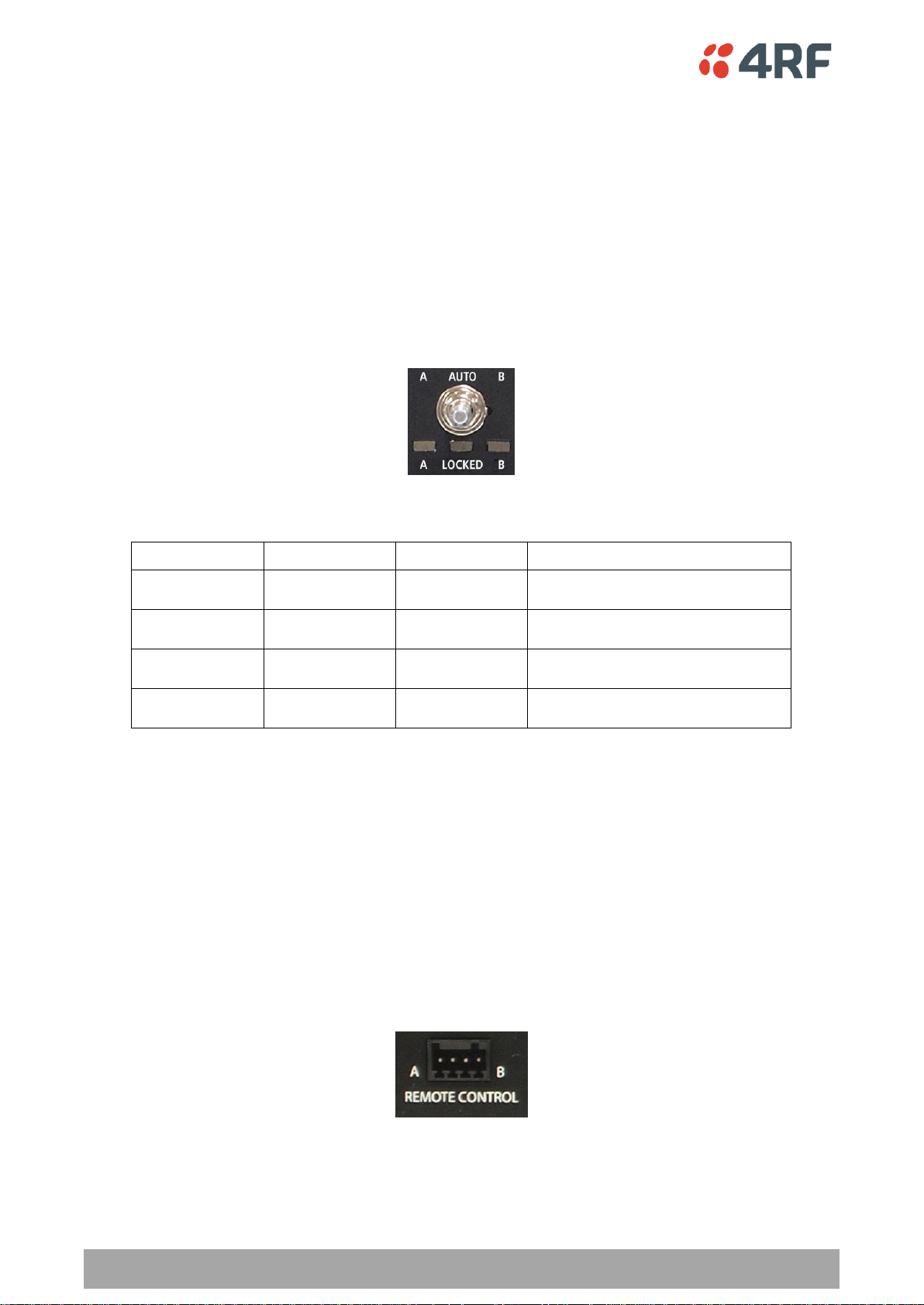
Switch Over
The switch over to the standby radio can be initiated automatically, on fault detection, or manually via
the Hardware Manual Lock switch on the Protection Switch or the Software Manual Lock from SuperVisor.
Additionally, it is possible to switch over the radios remotely without visiting the station site, via the
remote control connector on the front of the Protection Switch.
On detection of an alarm fault the switch over time is less than 0.5 seconds. Some alarms may take up to
5 seconds to be detected.
The Protection Switch has a switch guard mechanism to prevent protection switch oscillation. If a switchover has occurred, subsequent switch-over triggers will be blocked if the guard time has not elapsed.
The guard time starts at 20 seconds and doubles each switch-over to a maximum of 320 seconds and
halves after a period of two times the last guard time with no protection switch-overs.
Switching Criteria
The Protected Station will switch over operation from the active to the standby radio if any of the
configurable alarm events occur, or if there is a loss of the ‘keep alive’ signal from the active radio.
It is possible to configure the alarm events which will trigger the switch over. It is also possible to prevent
an alarm event triggering a switch over through the configuration of blocking criteria.
Any of the following alarm events can be set to trigger or prevent switching from the active radio to the
standby radio (see ‘Events > Events Setup’ on page 137).
It will not attempt to switch over to a standby radio which has power failure.
It will also not switch over to a standby radio with an active alarm event which has been configured as a
‘blocking criteria’.
30 | Product Options
Aprisa SR User Manual
A LED
B LED
Locked LED
State
Green
Off
Off
Auto - Radio A is active
Off
Green
Off
Auto - Radio B is active
Green
Off
Orange
Manual Lock to radio A
Off
Green
Orange
Manual Lock to radio B
Switch over will be initiated once either of these conditions is rectified, i.e. power is restored or the
alarm is cleared.
Hardware Manual Lock
The Hardware Manual Lock switch on the Protection Switch provides a manual override of the active /
standby radio.
When this lock is activated, the selected radio (A or B) becomes the active radio regardless of the
Software Manual Lock and the current switching or block criteria.
When the lock is deactivated (set to the Auto position), the protection will become automatic and
switching will be governed by normal switching and blocking criteria.
The state of the switch is indicated by the three LEDs on the Protection Switch:
The Protection Switch also has a Software Manual Lock (see ‘Protected Station: Maintenance > Protection’
on page 179). The Hardware Manual Lock takes precedence over Software Manual Lock if both diagnostic
functions are activated i.e. if the Software Manual Lock is set to ‘Primary’ and the Hardware Manual Lock
set to ‘Secondary’, the system will set the Secondary radio to Active.
When a Hardware Manual Lock is deactivated (set to the Auto position), the Software Manual Lock is reevaluated and locks set appropriately.
Remote Control
The switch over to the standby radio can be initiated via the Remote Control connector on the front of the
Protection Switch. This control will only operate if the Hardware Manual Lock switch is set to the Auto
position.
The inputs are logic inputs with 4700 Ω pullup to +3.3 VDC. They require a pull down to ground to activate
the control. The ground potential is available on the connector (see ‘Protection Switch Remote Control
Connections’ on page 215).
Product Options | 31
Aprisa SR User Manual
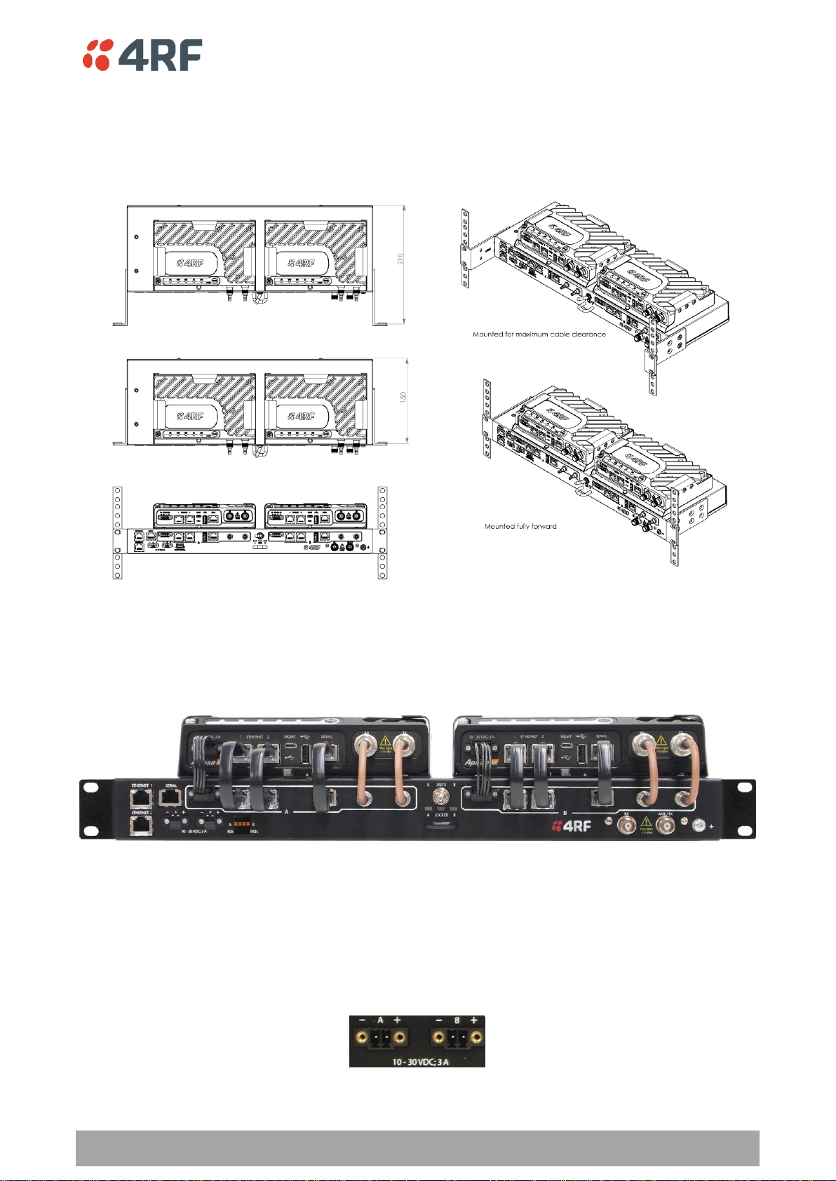
Installation
Mounting
The Aprisa SR Protected Station is designed to mount in a standard 19 inch rack.
Cabling
The Aprisa SR Protected Station is delivered pre-cabled with power, interface, management and RF
cables.
The set of interconnect cables is available as a spare part (see ‘Spares’ on page 34).
Power
A +10.5 to +30 V DC external power source must be connected to both the A and B Phoenix Contact 2 pin
male power connectors. The maximum combined power consumption is 35 Watts.

32 | Product Options
Aprisa SR User Manual
Maintenance
Changing the Protected Station IP Addresses
To change the IP address of a Protected Station radio:
1. Change the IP address of either or both the Primary Radio and Secondary radio (see ‘Protected
Station: Ethernet > Controller Setup’ on page 176). Changes in these parameters are automatically
changed in the partner radio.
Protected Station Software Upgrade
The Protected Station software upgrade can be achieved without disruption to traffic.
Network Software Upgrade
This process allows customers to upgrade their Aprisa SR network from the central base station location
without need for visiting remote sites.
The Software Pack is loaded into the base station with the file transfer process (see ‘Software > File
Transfer’ on page 146) and distributed via the radio link to all remote stations.
When all remote stations receive the Software Pack version, the software can be remotely activated on all
remote stations.
Single Radio Software Upgrade
USB Boot Upgrade Method
Assuming the Primary radio is active and the Secondary radio is standby
1. Using the Hardware Manual Lock switch, force the primary radio to active.
2. Insert the USB flash drive with the new software release into the secondary radio Host Port .
3. Power cycle the secondary radio. The radio will be upgraded with the new software.
4. When the secondary radio upgrade is completed, remove the USB flash drive, power cycle the
secondary radio and wait for it to become standby.
5. Using the Hardware Manual Lock switch, force the secondary radio to active.
6. Insert the USB flash drive with the new software release into the primary radio Host Port .
7. Power cycle the primary radio. The radio will be upgraded with the new software.
8. When the primary radio upgrade is completed, remove the USB flash drive, power cycle the primary
radio and wait for it to become standby.
9. Set the Hardware Manual Lock switch to the Auto position. The secondary radio will remain active and
the primary radio will remain standby. To set the primary radio to active, use the hardware lock
switch to select the primary radio and wait for it to become active, then set the hardware manual
lock switch to the Auto position.

Product Options | 33
Aprisa SR User Manual
Replacing a Protected Station Faulty Radio
Replacing a faulty radio in a Protected Station can be achieved without disruption to traffic.
Assuming that the primary radio is active and the secondary radio is faulty and needs replacement:
1. Ensure the replacement radio has the same version of software installed as the primary radio. If
necessary, upgrade the software in the replacement radio.
2. Set the RF Interface MAC Address (see ‘Maintenance > Advanced’ on page 132). This MAC address is
present on chassis label.
3. Using SuperVisor > Maintenance > Advanced ‘Save Configuration to USB’ and ‘Restore Configuration
from USB’ operation, clone the primary radio’s configuration to the replacement radio.
4. Configure the replacement radio as the secondary radio and setup the IP address and other protection
parameters (see ‘Terminal > Operating Mode’ on page 80).
5. Set the Hardware Manual Lock switch to make the primary radio active.
6. Carefully remove the faulty radio from the protection switch and install the replacement radio.
7. Power on the replacement radio and wait for it to become standby.
8. Set the Hardware Manual Lock switch to the Auto position.

34 | Product Options
Aprisa SR User Manual
Part Number
Part Description
APSP-SRPSW
4RF Spare, Aprisa SR, Protection Switch
Part Number
Part Description
APSP-SRPSC-ST6
4RF Spare, Aprisa SR, Protection Switch Cables, Set Of 6
Spares
The Aprisa SR Protection Switch is available as a spare part. This spare includes the protection switch and
two sets of Protection Switch interconnect cables (one set is 6 cables).
The set of interconnect cables is available as a spare part (set of 6 cables).
Replacing a Faulty Protection Switch
Note: Replacing a faulty Protection Switch will disrupt traffic.
Move the radios, the interconnect cables, the interface cables and the power cables to the replacement
Protection Switch.
On both Protected Station radios:
1. Power on the radio and wait for it to become ready.
2. Using SuperVisor > Maintenance > Advanced, enter the RF Interface MAC address shown on the
Protection Switch label (see ‘RF Interface MAC address’ on page 133).
3. Using SuperVisor > Maintenance > Advanced, Decommission the node (see ‘Decommission Node’ on
page 133) and then Discover the Nodes (see ‘Discover Nodes’ on page 133).
Ensure that the Hardware Manual Lock switch is set to the Auto position.
The Aprisa SR Protected Station is now ready to operate.
Product Options | 35
Aprisa SR User Manual
Part Number
Part Description
APSR-D400-012-DO-12-ETAA
4RF SR, PD, 400-470 MHz, 12.5 kHz, DO, 12 VDC, ET, AA
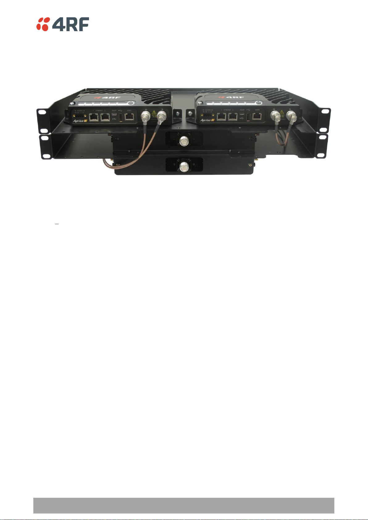
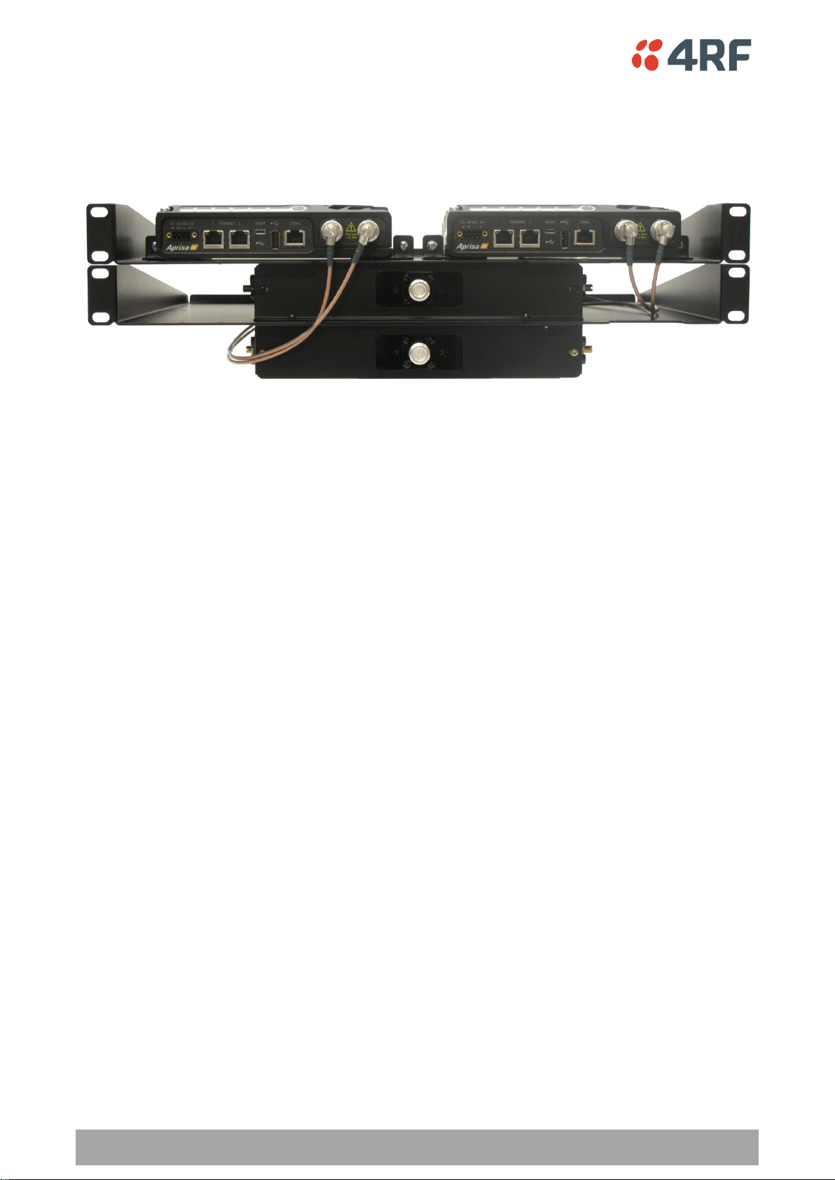
Data Driven Protected Station
The Aprisa SR Data Driven Protected Station provides radio and RS-232 serial port user interface
protection for Aprisa SR radios.
Example Part:
The Aprisa SR Data Driven Protected Station shown is comprised of two standard Aprisa SR dual antenna
port option radios and two external duplexers mounted on 19" rack mounting shelves.
The Aprisa SR radios can be any of the currently available Aprisa SR radio frequency bands, channel sizes
or single / dual antenna port options.
By default, the Aprisa SR Data Driven Protected Station is configured with the left hand radio (A)
designated as the primary radio and the right hand radio (B) designated as the secondary radio.
Each radio is configured with its own unique IP and MAC address and the address of the partner radio.
On power-up, the primary radio will assume the active role and the secondary radio will assume the
standby role. If, for some reason, only one radio is powered on it will automatically assume the active
role.
Operation
The active radio is determined explicitly by which radio receives data on its RS-232 serial port input from
the interface.
The active radio carries all RS-232 serial traffic over its radio link and the standby radio is unused with its
transmitter turned off.
If data is received on the RS-232 serial port interface input of the standby radio, it will immediately
become the active radio and the radio which was active will become the standby radio.

36 | Product Options
Aprisa SR User Manual
Switch Over
The active radio is determined explicitly by which radio receives data on its RS-232 serial port.
The switching and blocking criteria used for the standard Protected Station do not apply. This means that
events and alarms on the unit are not used as switching criteria.
Configuration Management
The Primary and Secondary radios are managed with the embedded web-based management tool,
SuperVisor (see ‘Managing the Radio’ on page 59) by using either the Primary or Secondary IP address.
Configuration changes in one of the radios will automatically be reflected in the partner radio.
Changes to the Network Table are automatically synchronized from the active radio to the standby radio
but the Network Table is only visible on the active radio.
Product Options | 37
Aprisa SR User Manual
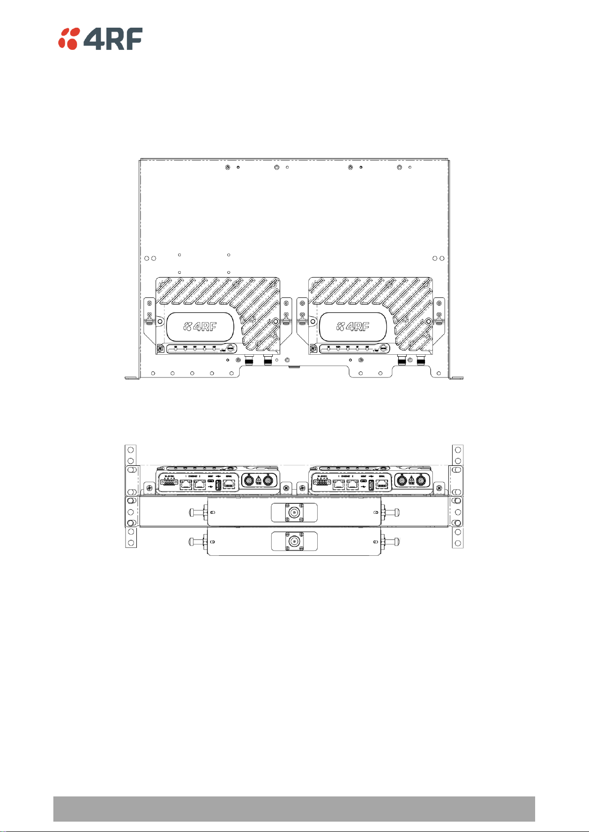
Installation
Mounting
The Aprisa SR Data Driven Protected Station is designed to mount in a standard 19” rack on two 1U rack
mounting shelves.
38 | Product Options
Aprisa SR User Manual
Cabling
The Aprisa SR Data Driven Protected Station is delivered with the radios, duplexers, rack mounting shelves
and RF cables.
The picture demonstrates the RF cabling but the product is delivered with the cables separately packaged.
The set of interconnect cables is available as a spare part.
Power
A +10.5 to +30 V DC external power source must be connected to both the A and B Phoenix Contact 4 pin
male power connectors. The maximum combined power consumption is 35 Watts.

Product Options | 39
Aprisa SR User Manual
Part Number
Part Number
APSA-KDUP-400-B1
4RF SR Acc, Kit, Duplexer, 400-470 MHz, s 5 MHz, p 0.5 MHz, ext
Duplexer Kit
The Aprisa SR product range contains a Duplexer Kit accessory.
This kit provides a 19” rack mounted duplexer for use with the Dual Antenna port Aprisa SR radio.
The Aprisa SR Duplexer Kit contains:
1x 1U 19" rack mount shelf with duplexer mounting brackets and screws
1x Duplexer
2x TNC to SMA right angle 590mm cables
Aprisa SR Duplexer Kit example with a 400 MHz B1 duplexer:

40 | Product Options
Aprisa SR User Manual
Part Number
Part Number
APSA-IFCA-USB-MS-16
4RF SR Acc, Cable, Interface, USB Converter, Multi-strand, 1.6m
Part Number
Part Number
APSA-KFCA-USB-45-MF-04
4RF SR Acc, Kit, Interface, USB Converter, RJ45, Female, 0.4m
Part Number
Part Number
APSA-KFCA-USB-D9-MF-04
4RF SR Acc, Kit, Interface, USB Converter, DB9, Female, 0.4m
USB RS-232 Serial Port
The Aprisa SR USB host port is predominantly used for software upgrade and diagnostic reporting.
However, it can also be used to provide an additional RS-232 DCE serial port for customer traffic.
This is accomplished with a USB to RS-232 serial converter cable. This plugs into the USB host port
connector and can be terminated with the required customer connector.
This additional RS-232 serial port is enabled with the SuperVisor mode setting in Serial Port Settings (see
‘Serial > Port Setup’ on page 95).
USB RS-232 operation
The USB serial converter buffers the received data frames into 64 byte blocks separated by a small interframe gap.
For the majority of applications, this fragmentation of egress frames is not an issue. However, there are
some applications that may be sensitive to the inter-frame gap, therefore, these applications need
consideration.
A 5 ms inter-frame is recommended for the applications that are sensitive to inter-frame gap timings.
On a USB RS-232 port, Modbus RTU can operate up to 9600 baud with all packet sizes and up to 115200 if
the packet size is less than 64 bytes. The standard RS-232 port is fully compatible with Modbus RTU at all
baud rates.
Cabling Options
The following converter cables are available as Aprisa SR accessories to provide the customer interface:
1. USB Converter to 1.6 metre multi-strand cable 6 wire for termination of customer connector
2. USB converter to RJ45 female kit for USB to RS-232 DCE conversion. The RJ45 is mounted in a strain
relief retention bracket.
3. USB converter to DB9 female kit for USB to RS-232 DCE conversion. The DB9 is mounted in a strain
relief retention bracket.

Implementing the Network | 41
Aprisa SR User Manual
5. Implementing the Network
Network Topologies
The following are examples of typical network topologies:
Point-To-Point Network
Point-to-Multipoint Network
Point-to-Multipoint with Repeater 1
Point-to-Multipoint with Repeater 2

42 | Implementing the Network
Aprisa SR User Manual
Initial Network Deployment
Install the Base Station
To install the base station in your FAN (Field Area Network):
1. Install the base station radio (see ‘Installing the Radio’ on page 52).
2. Set the radio Network ID (FAN) to a unique ID in your entire network (see ‘Terminal > Device’ on page
78).
3. Set the radio IP address (see ‘Terminal > Device’ on page 78).
4. Set the radio frequencies to the frequencies you wish to operate from (see ‘Radio > Basic’ on page
85).
5. Set the radio operating mode to ‘base station’ (see ‘Terminal > Operating Mode’ on page 80).
6. Set the radio security settings (see ‘Security > Setup’ on page 109).
Installing the Remote Stations
To install the remote stations in your FAN:
1. Install the remote station radio (see ‘Installing the Radio’ on page 52).
2. Set the radio Network ID (FAN) to the same ID as the other stations in the FAN (see ‘Terminal >
Device’ on page 78).
3. Set the radio IP address (see ‘Terminal > Device’ on page 78).
4. Set the radio frequencies to the base station / repeater station frequencies you wish to operate from
(see ‘Radio > Basic’ on page 85).
5. Set the radio operating mode to ‘remote station’ (see ‘Terminal > Operating Mode’ on page 80).
6. Set the radio security settings to the same as the base station (see ‘Security > Setup’ on page 109).
The base station will automatically allocate a node address to the new remote station.
Install a Repeater Station
To install a repeater station in your FAN:
1. Install the repeater station radio (see ‘Installing the Radio’ on page 52).
2. Set the radio Network ID (FAN) to the same ID as the other stations in the FAN (see ‘Terminal >
Device’ on page 78).
3. Set the radio IP address (see ‘Terminal > Device’ on page 78).
4. Set the radio frequencies to base station frequencies you wish to operate from (see see ‘Radio > Basic’
on page 85).
5. Set the radio operating mode to ‘repeater station’ (see ‘Terminal > Operating Mode’ on page 80).
6. Set the radio security settings to the same as the base station (see ‘Security > Setup’ on page 109).
7. Increase the radio network radius by one on all stations in the FAN (see ‘Terminal > Device’ on page
78).
The base station will automatically allocate a node address to the new repeater station.

Implementing the Network | 43
Aprisa SR User Manual
Network Changes
Adding a Repeater Station
To add a repeater station to your FAN:
1. Install the repeater station radio (see ‘Installing the Radio’ on page 52).
2. Set the radio Network ID (FAN) to the same ID as the other stations in the FAN (see ‘Terminal >
Device’ on page 78).
3. Set the radio IP address (see ‘Terminal > Device’ on page 78).
4. Set the radio frequencies to the base station frequencies you wish to operate from (see ‘Radio > Basic’
on page 85).
5. Set the radio operating mode to ‘repeater station’ (see ‘Terminal > Operating Mode’ on page 80).
6. Increase the radio network radius by one on all stations in the FAN (see ‘Terminal > Device’ on page
78).
The base station will automatically allocate a node address to the new repeater station.
To remove a repeater station from your FAN:
1. Turn the power off on the remote station radios operating from the repeater station radio you wish to
remove.
2. Turn the power off on the repeater station radio you wish to remove.
3. Decrease the network radius by one on all stations in the FAN (see ‘Terminal > Device’ on page 78).
Adding a Remote Station
To add a remote station to your FAN:
1. Install the remote station radio (see ‘Installing the Radio’ on page 52).
2. Set the radio Network ID (FAN) to the same ID as the other stations in the FAN (see ‘Terminal >
Device’ on page 78).
3. Set the radio IP address (see ‘Terminal > Device’ on page 78).
4. Set the radio frequencies to the base station / repeater station frequencies you wish to operate from
(see ‘Radio > Basic’ on page 85).
5. Set the radio operating mode to ‘remote station’ (see ‘Terminal > Operating Mode’ on page 80).
The base station will automatically allocate a node address to the new remote station.
To remove a remote station from your FAN:
1. Turn the power off on the remote station radio you wish to remove. This is the only action that is
required.
Note: The remote station will continue to show in the Network Table list.


Preparation | 45
Aprisa SR User Manual
6. Preparation
Bench Setup
Before installing the links in the field, it is recommended that you bench-test the links. A suggested setup
for basic bench testing is shown below:
When setting up the equipment for bench testing, note the following:
Earthing
Each radio should be earthed at all times. The radio earth point should be connected to a protection
earth.
Attenuators
In a bench setup, there should be 60 - 80 dB at up to 1 GHz of 50 ohm coaxial attenuation, capable of
handling the transmit power of +37 dBm (5 W) between the radios’ antenna connectors.
Splitter
If more than two radios are required in your bench setup, a multi-way splitter is required. The diagram
shows a two way splitter. This splitter should be 50 ohm coaxial up to 1 GHz and capable of handling the
transmit power of +37 dBm (5 W).
Cables
Use double-screened coaxial cable that is suitable for use up to 1 GHz at ≈ 1 metre.
CAUTION: Do not apply signals greater than +10 dBm to the antenna connection as they can damage the
receiver.

46 | Preparation
Aprisa SR User Manual
Factor
Explanation
Frequency
Often used in 380-530 MHz bands
Gain
Varies with size (5 dBi to 8 dBi typical)
Wind loading
Minimal
Tower aperture required
Minimal
Size
Range from 2 m to 3 m length
Polarization
Vertical
Path Planning
The following factors should be considered to achieve optimum path planning:
Antenna Selection and Siting
Coaxial Cable Selection
Linking System Plan
Antenna Selection and Siting
Selecting and siting antennas are important considerations in your system design. The antenna choice for
the site is determined primarily by the frequency of operation and the gain required to establish reliable
links.
Base or Repeater Station
The predominant antenna for a base station or a repeater station is an omni-directional collinear gain
antenna.
Omni Directional Collinear Antennas
Preparation | 47
Aprisa SR User Manual
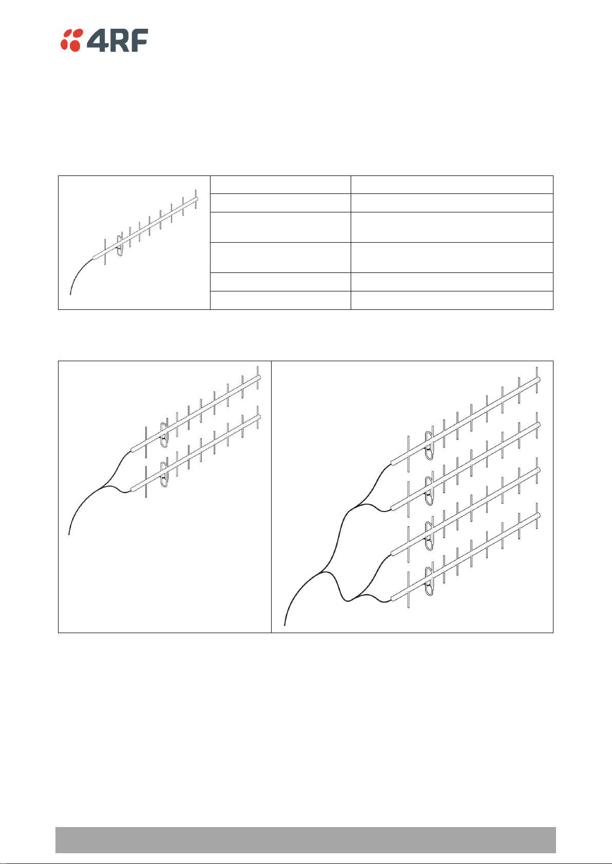
Factor
Explanation
Frequency
Often used in 350-600 MHz bands
Gain
Varies with size (typically 11 dBi to 16
dBi)
Stackable gain increase
2 Yagi antennas (+ 2.8 dB)
4 Yagi antennas (+ 5.6 dB)
Size
Range from 0.6 m to 3 m in length
Front to back ratio
Low (typically 18 to 20 dB)
Remote station
There are two main types of directional antenna that are commonly used for remote stations, Yagi and
corner reflector antennas.
Yagi Antennas
It is possible to increase the gain of a Yagi antenna installation by placing two or more of them in a stack.
The relative position of the antennas is critical.
Example of stacked antennas
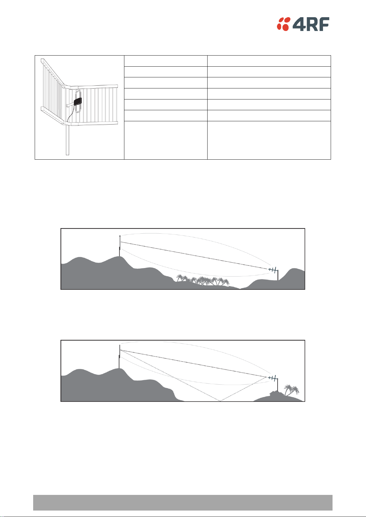
48 | Preparation
Aprisa SR User Manual
Factor
Explanation
Frequency
Often used in 330-960 MHz bands
Gain
Typically 12 dBi
Size
Range from 0.36 m to 0.75 m in length
Front to back ratio
High (typically 30 dB)
Beamwidth
Broad (up to 60°)
Corner Reflector Antennas
Antenna Siting
When siting antennas, consider the following points:
A site with a clear line of sight to the remote radio is recommended. Pay particular attention to trees,
buildings, and other obstructions close to the antenna site.
Example of a clear line-of-sight path
Any large flat areas that reflect RF energy along the link path, for instance, water, could cause multipath
fading. If the link path crosses a feature that is likely to cause RF reflections, shield the antenna from the
reflected signals by positioning it on the far side of the roof of the equipment shelter or other structure.
Example of a mid-path reflection path
The antenna site should be as far as possible from other potential sources of RF interference such as
electrical equipment, power lines and roads. The antenna site should be as close as possible to the
equipment shelter.
Wide angle and zoom photographs taken at the proposed antenna location (looking down the proposed
path), can be useful when considering the best mounting positions.

Preparation | 49
Aprisa SR User Manual
Factor
Effect
Attenuation
Short cables and larger diameter cables have less attenuation
Cost
Smaller diameter cables are cheaper
Ease of installation
Easier with smaller diameter cables or short cables
Part Number
Part Description
Specification
RFS LCF78 50JA
Feeder Cable, 7/8’, CELLFLEX, Low
Loss, Std, /m, MOQ 50
Low loss 7/8’ (22.2 mm) feeder cable
Bending radius of 125 mm min
Attenuation of 2.5 dB / 100m @ 450 MHz
RFS LCF12 50J
Feeder Cable, 1/2’, CELLFLEX, Low
Loss, Std, /m, MOQ 50
Low loss 0.5’ (12.7 mm) feeder cable
Bending radius of 125 mm min
Attenuation of 4.7 dB / 100m @ 450 MHz
RFI CNT 400
Feeder, CNT-400, 10.8mm, Double
Shielded Solid Polyethylene
Low loss 0.4’ (10.8 mm) feeder cable
UV protected black Polyethylene, bonded
AL tape outer conductor
Bending radius of 30 mm min
Attenuation of 8.8 dB / 100m @ 450 MHz
Part Number
Part Description
Specification
RFI 8223
Feeder, RG 223 5.4mm d, Double
Shielded Solid Polyethylene
Bending radius of 20 mm min
Attenuation of 30.5 dB / 100m @ 450 MHz
Coaxial Feeder Cables
To ensure maximum performance, it is recommended that you use good quality low-loss coaxial cable for
all feeder runs. When selecting a coaxial cable consider the following:
For installations requiring long feeder cable runs, use the LCF78, LCF12 or CNT-400 feeder cable or
equivalent:
For installations requiring short feeder cable runs, use the RFI 8223 feeder cable or equivalent:
When running cables:
Run coaxial feeder cable from the installation to the antenna, ensuring you leave enough extra cable at
each end to allow drip loops to be formed.
Terminate and ground the feeder cables in accordance with the manufacturers’ instructions. Bond the
outer conductor of the coaxial feeder cables to the base of the tower mast.
Linking System Plan
All of the above factors combine in any proposed installation to create a Linking System Plan. The Linking
System Plan predicts how well the radios will perform after it is installed.
Use the outputs of the Linking System Plan during commissioning to confirm the radios have been installed
correctly and that it will provide reliable service.
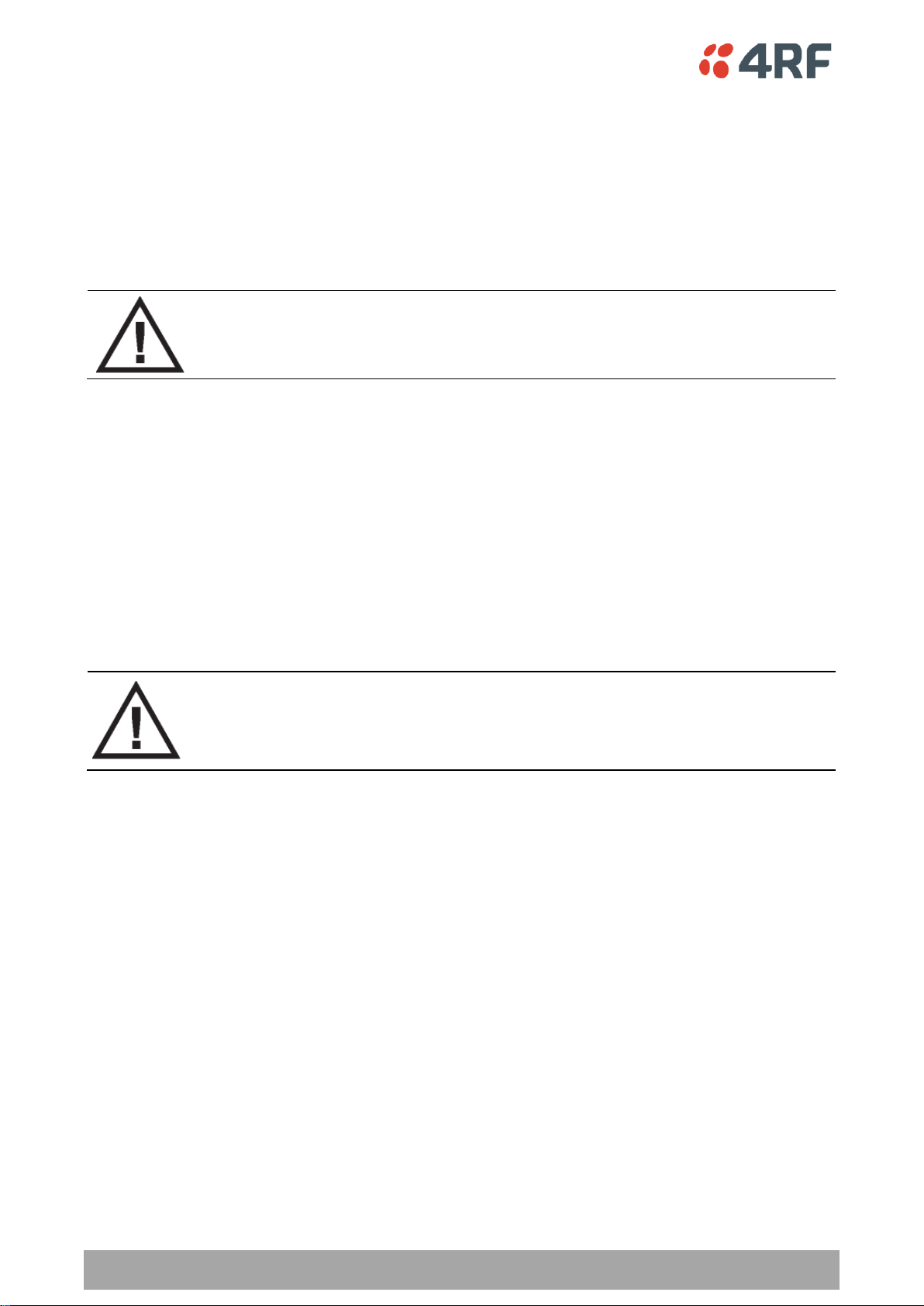
50 | Preparation
Aprisa SR User Manual
WARNING:
Before connecting power to the radio, ensure that the radio is grounded via the
negative terminal of the DC power connection.
Operating temperature
-40 to +70˚ C
Storage temperature
-40 to +80˚ C
Humidity
Maximum 95% non-condensing
WARNING:
If the Aprisa SR is operated in an environment where the ambient temperature
exceeds 50°C, the Aprisa SR must be installed within a restricted access location to
prevent human contact with the enclosure heatsink.
Site Requirements
Power Supply
Ensure a suitable power supply is available for powering the radio.
The nominal input voltage for a radio is +13.8 VDC (negative earth) with an input voltage range of +10 to
+30 VDC. The maximum power input is 30 W.
Equipment Cooling
If the Aprisa SR is operated in an environment where the ambient temperature exceeds 50°C, the Aprisa
SR convection air flow over the heat sinks must be considered.
The environmental operating conditions are as follows:
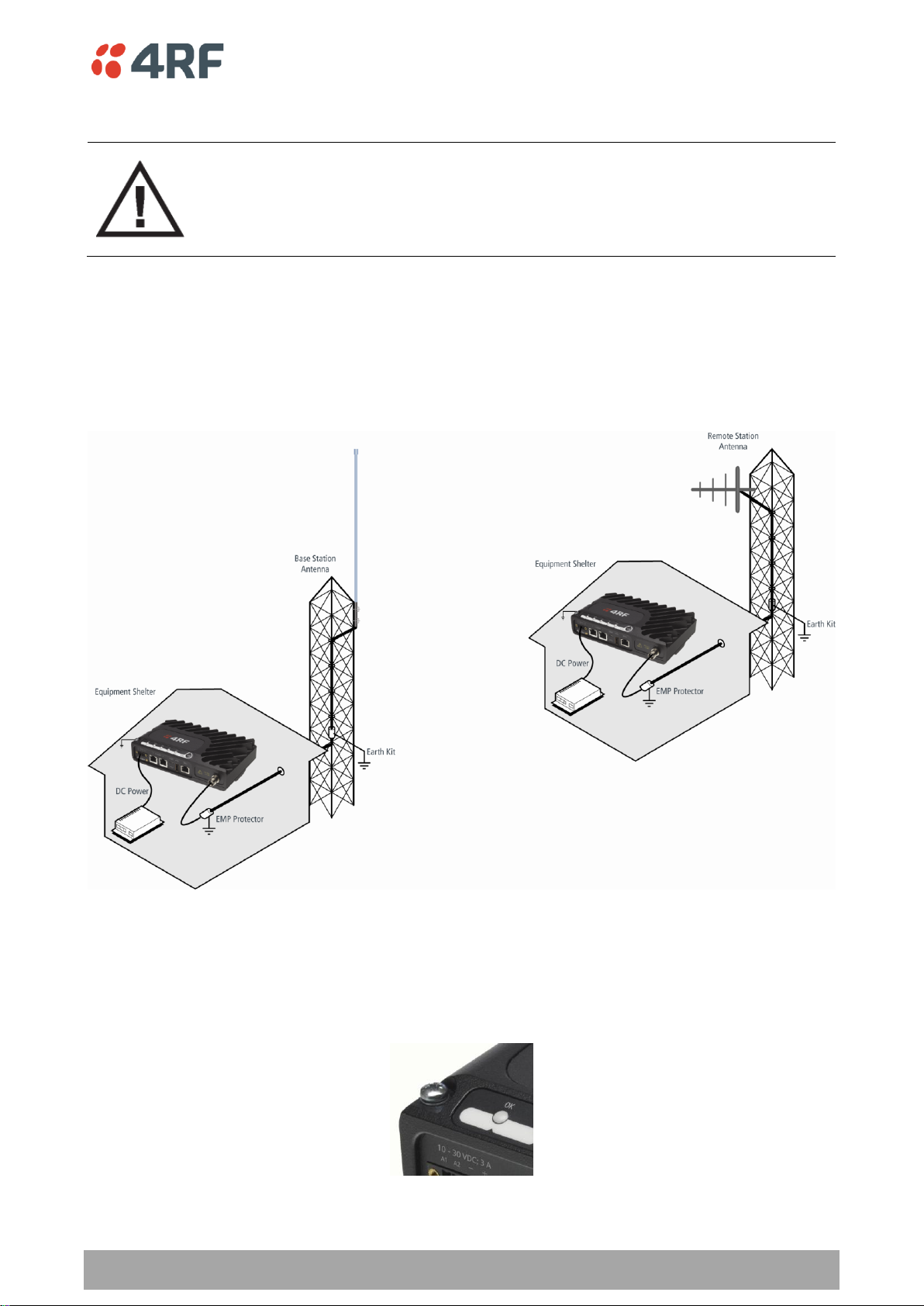
Preparation | 51
Aprisa SR User Manual
WARNING:
Lightning can easily damage electronic equipment.
To avoid this risk, install primary lightning protection devices on any interfaces that
are reticulated in the local cable network.
You should also install a coaxial surge suppressor on the radio antenna port.
Earthing and Lightning Protection
Feeder Earthing
Earth the antenna tower, feeders and lightning protection devices in accordance with the appropriate
local and national standards. The diagram below shows the minimum requirements.
Use grounding kits as specified or supplied by the coaxial cable manufacturer to properly ground or bond
the cable outer.
Radio Earthing
The Aprisa SR has an earth connection point on the top left of the enclosure. A M4 8mm pan pozi machine
screw and a M4 lock washer is supplied fitted to the radio. This can be used to earth the enclosure to a
protection earth.
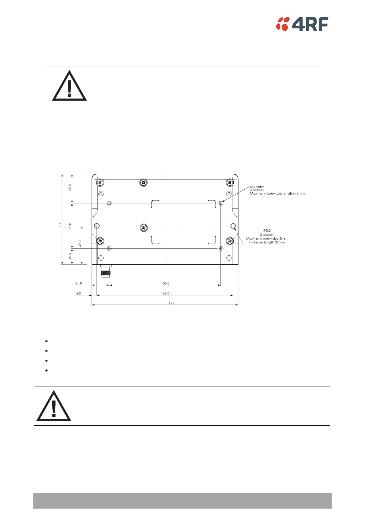
52 | Installing the Radio
Aprisa SR User Manual
CAUTION:
You must comply with the safety precautions in this manual or on the product
itself.
4RF does not assume any liability for failure to comply with these precautions.
WARNING:
If the Aprisa SR is operated in an environment where the ambient temperature
exceeds 50°C, the Aprisa SR must be installed within a restricted access location to
prevent human contact with the enclosure heatsink.
7. Installing the Radio
Mounting
The Aprisa SR has four threaded holes (M4) in the enclosure base and two holes (5.2 mm) through the
enclosure for mounting.
Mounting options include:
DIN rail mounting with the Aprisa SR DIN Rail Mounting Bracket
Rack shelf mounting
Wall mounting
Outdoor enclosure mounting
Required Tools
No special tools are needed to install the radio.

Installing the Radio | 53
Aprisa SR User Manual
Part Number
Part Description
APSA-MBRK-DIN
4RF Aprisa SR Acc, Mounting, Bracket, DIN Rail
DIN Rail Mounting
The Aprisa SR has an optional accessory part to enable the mounting on a standard DIN rail:
The Aprisa SR is mounted into the DIN rail mounting bracket using the four M4 threaded holes in the Aprisa
SR enclosure base. Four 8 mm M4 pan pozi machine screws are supplied with the bracket.
The Aprisa SR DIN rail mounting bracket can be mounted in four positions on a horizontal DIN rail:
Vertical Mount (vertical enclosure perpendicular to the mount)
Horizontal Mount (horizontal enclosure perpendicular to the mount)
Flat Vertical Mount (vertical enclosure parallel to the mount)
Flat Horizontal Mount (horizontal enclosure parallel to the mount)
The DIN rail mounting bracket has two clips which are positioned to allow for the four mounting positions.
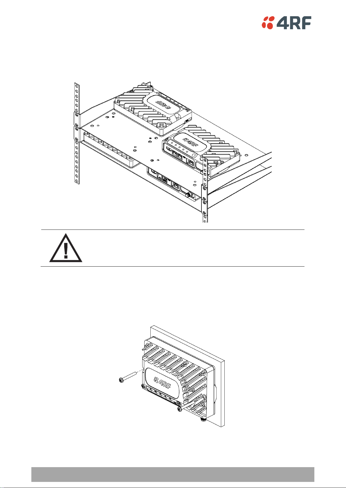
54 | Installing the Radio
Aprisa SR User Manual
WARNING:
If the Aprisa SR is operated in an environment where the ambient temperature
exceeds 50°C, the Aprisa SR convection air flow over the heat sinks must be
considered.
Rack Shelf Mounting
The Aprisa SR can be mounted on a rack mount shelf using the four M4 threaded holes in the Aprisa SR
enclosure base. The following picture shows Aprisa SR mounted on 1 RU rack mounted shelves.
Wall Mounting
The Aprisa SR can be mounted on a wall using the two holes through the enclosure (5.2 mm diameter).
Typically, M5 screws longer than 35 mm would be used.
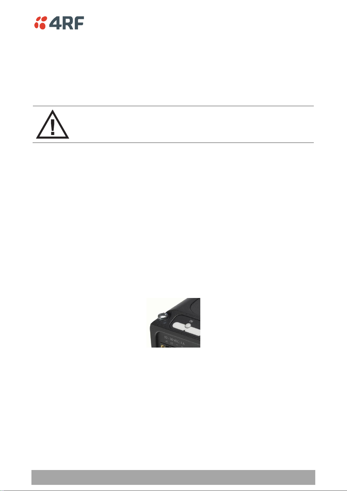
Installing the Radio | 55
Aprisa SR User Manual
WARNING:
When the link is operating, there is RF energy radiated from the antenna.
Do not stand in front of the antenna while the radio is operating (see the ‘RF
Exposure Warning’ on page 3).
Installing the Antenna and Feeder Cable
Carefully mount the antenna following the antenna manufacturers’ instructions. Run feeder cable from
the antenna to the radio location.
Lightning protection must be incorporated into the antenna system (see ‘Earthing and Lightning
Protection’ on page 51).
Fit the appropriate male or female connector (usually N-type) to the antenna feeder at the antenna end.
Carefully follow the connector manufacturers’ instructions.
Securely attach the feeder cable to the mast and cable trays using cable ties or cable hangers. Follow the
cable manufacturer’s recommendations about the use of feeder clips, and their recommended spacing.
Connect the antenna and feeder cable. Weatherproof the connection with a boot, tape or other approved
method.
The Aprisa SR antenna connection is a TNC female connector so the feeder / jumper must be fitted with a
TNC male connector.
If a jumper is used between the feeder and the radio, connect a coaxial surge suppressor or similar
lightning protector between the feeder and jumper cables (or at the point where the cable enters the
equipment shelter). Connect the feeder cable to the antenna port on the radio.
Earth the case of the lightning protector to the site Lightning Protection Earth.
The Aprisa SR has an earth connection point on the top left of the enclosure. A M4 8mm pan pozi machine
screw and a M4 lock washer is supplied fitted to the radio. This can be used to earth the enclosure to a
protection earth.

56 | Installing the Radio
Aprisa SR User Manual
Part Number
Part Description
APSA-CPH4-FEM-01
4RF Aprisa SR Acc, Connector, Phoenix 4 pin, Female, 1 item
Part Number
Part Description
APSA-P230-030-24-TS
4RF Aprisa SR Acc, PSU, 230 VAC, 30W, 24 VDC, -10 to +60C
APSA-P230-048-24-TE
4RF Aprisa SR Acc, PSU, 230 VAC, 48W, 24 VDC, -20 to +75C
APSA-P230-060-24-TS
4RF Aprisa SR Acc, PSU, 230 VAC, 60W, 24 VDC, -10 to +60C
APSA-P48D-050-24-TA
4RF Aprisa SR Acc, PSU, 48 VDC, 50W, 24 VDC, 0 to +50C
Connecting the Power Supply
The nominal input voltage for a radio is +13.8 VDC (negative earth) with an input voltage range of +10 to
+30 VDC. The maximum power input is 30 W.
The power connector required is a Phoenix Contact 4 pin female screw fitting part MC 1.5/ 4-STF-3.5. This
connector is supplied fitted to the radio.
The negative supply of the Aprisa SR power connection is internally connected to the Aprisa SR enclosure.
Power must be supplied from a Negative Earthed power supply.
Wire your power source to power connector and plug the connector into the radio. The connector screws
can be fastened to secure the connector.
Additional Phoenix Contact 4 pin female power connectors can be ordered from 4RF:
Turn your power source on:
All the radio LEDs will flash orange for one second and then the OK, DATA and CPU LEDs will light
green, the RF LED will light orange and the AUX LED will be off
The Aprisa SR radio is ready to operate
The RF LED will light green when the radio is registered with the FAN
If the LEDs fail to light, carefully check the supply polarity. If the power supply connections have been
accidentally reversed, internal fuses will have blown to protect the unit.
Spare fuses are contained within the radio, see ‘Spare Fuses’ on page 57 for instructions on how to locate
and replace the fuses.
External Power Supplies
The following external power supplies are available from 4RF as accessories:

Installing the Radio | 57
Aprisa SR User Manual
Spare Fuses
The Aprisa SR PBA contains two fuses in the power input with designators F2 and F3. Both the positive and
negative power connections are fused. The fuse type is a Littelfuse 0453005 with a rating of 5 A, 125 V,
very fast acting.
To replace the fuses:
1. Remove the input power and antenna cable.
2. Unscrew the enclosure securing screws (posi 2).
2. Separate the enclosure halves.
CAUTION: Antistatic precautions must be taken as the internal components are static sensitive.
3. Access the enclosure spare fuses under the plastic cap.

58 | Installing the Radio
Aprisa SR User Manual
Part Number
Part Description
APSA-FNAN-453-05-02
4RF Aprisa SR Acc, Fuse, Nano SMF, 453 Series, 5A, 2 items
4. Replace the two fuses.
5. Close the enclosure and tighten the screws.
Note: Is it critical that the screws are re-tightened to 1.2 Nm. The transmitter adjacent channel
performance can be degraded if the screws are not tightened correctly.
Additional Spare Fuses
Additional spare fuses can be ordered from 4RF:

Managing the Radio | 59
Aprisa SR User Manual
8. Managing the Radio
SuperVisor
The Aprisa SR contains an embedded web server application (SuperVisor) to enable element management
with any major web browser (such as Mozilla Firefox or Microsoft® Internet Explorer).
SuperVisor enables operators to configure and manage the Aprisa SR base station radio and repeater /
remote station radios over the radio link.
The key features of SuperVisor are:
Full element management, configuration and diagnostics
Manage the entire FAN (Field Area Network) from the Base Station (remote management of
elements)
Managed network software distribution and upgrades
Performance and alarm monitoring of the entire network, including RSSI, alarm states, time-
stamped events, etc.
View and set standard radio configuration parameters including frequencies, transmit power,
channel access, serial, Ethernet port settings
Set and view security parameters
User management
Connecting to SuperVisor
The predominant management connection to the Aprisa SR radio is with an Ethernet interface using
standard IP networking. There should be only one Ethernet connection from any radio in the FAN to the
management network.
The Aprisa SR has a factory default IP address of 169.254.50.10 with a subnet mask of 255.255.0.0. This is
an IPv4 Link Local (RFC3927) address which simplifies the connection to a PC.
Each radio in the FAN must be set up with a unique IP address on the same subnet.
The Aprisa SR Protected Station radio A (left radio) has a factory default IP address of 169.254.50.10 and
radio B (right radio) has a factory default IP address of 169.254.50.20, both with a subnet mask of
255.255.0.0.
To change the Aprisa SR IP address:
1. Set up your PC for a compatible IP address e.g. 169.254.50.1 with a subnet mask of 255.255.0.0.
2. Connect your PC network port to one of the Aprisa SR Ethernet ports.
3. Open a browser and enter http://169.254.50.10.
4. Login to the radio with the default Username ‘admin’ and Password ‘admin’.
5. Change the IP address to conform to the network plan in use.

60 | Managing the Radio
Aprisa SR User Manual
Management PC Connection
The active management PC must only have one connection to the FAN as shown by path . There should
not be any alternate path that the active management PC can use via an alternate router or alternate LAN
that would allow the management traffic to be looped as shown by path .
When logging into a FAN, it is important to understand the relationship between the Local Radio and the
Remote Radios.
The Local Radio is the radio that your IP network is physically connected to.
If the Local Radio is a base station, SuperVisor manages the base station and all the repeater stations and
remote stations in the FAN.
If the Local Radio is a remote station or repeater station, SuperVisor only manages the remote / repeater
station radio logged into.

Managing the Radio | 61
Aprisa SR User Manual
PC Settings for SuperVisor
To change the PC IP address:
If your PC has previously been used for other applications, you may need to change the IP address and the
subnet mask settings. You will require Administrator rights on your PC to change these.
Windows XP example:
1. Open the ‘Control Panel’.
2. Open ‘Network Connections’ and right click on the ‘Local Area Connection’ and select ‘Properties’.
3. Click on the ‘General’ tab.
4. Click on ‘Internet Protocol (TCP/IP)’ and click on properties.
5. Enter the IP address and the subnet mask (example as shown).
6. Click ‘OK’ then close the Control Panel.
If the radio is on a different subnet from the network the PC is on, set the PC default gateway address to
the network gateway address which is the address of the router used to connect the subnets (for details,
consult your network administrator).

62 | Managing the Radio
Aprisa SR User Manual
To change the PC connection type:
If your PC has previously been used with Dial-up connections, you may need to change your PC Internet
Connection setting to ‘Never dial a connection’.
Windows Internet Explorer 8 example:
1. Open Internet Explorer.
2. Open the menu item Tools > Internet Options and click on the ‘Connections’ tab.
3. Click the ‘Never dial a connection’ option.
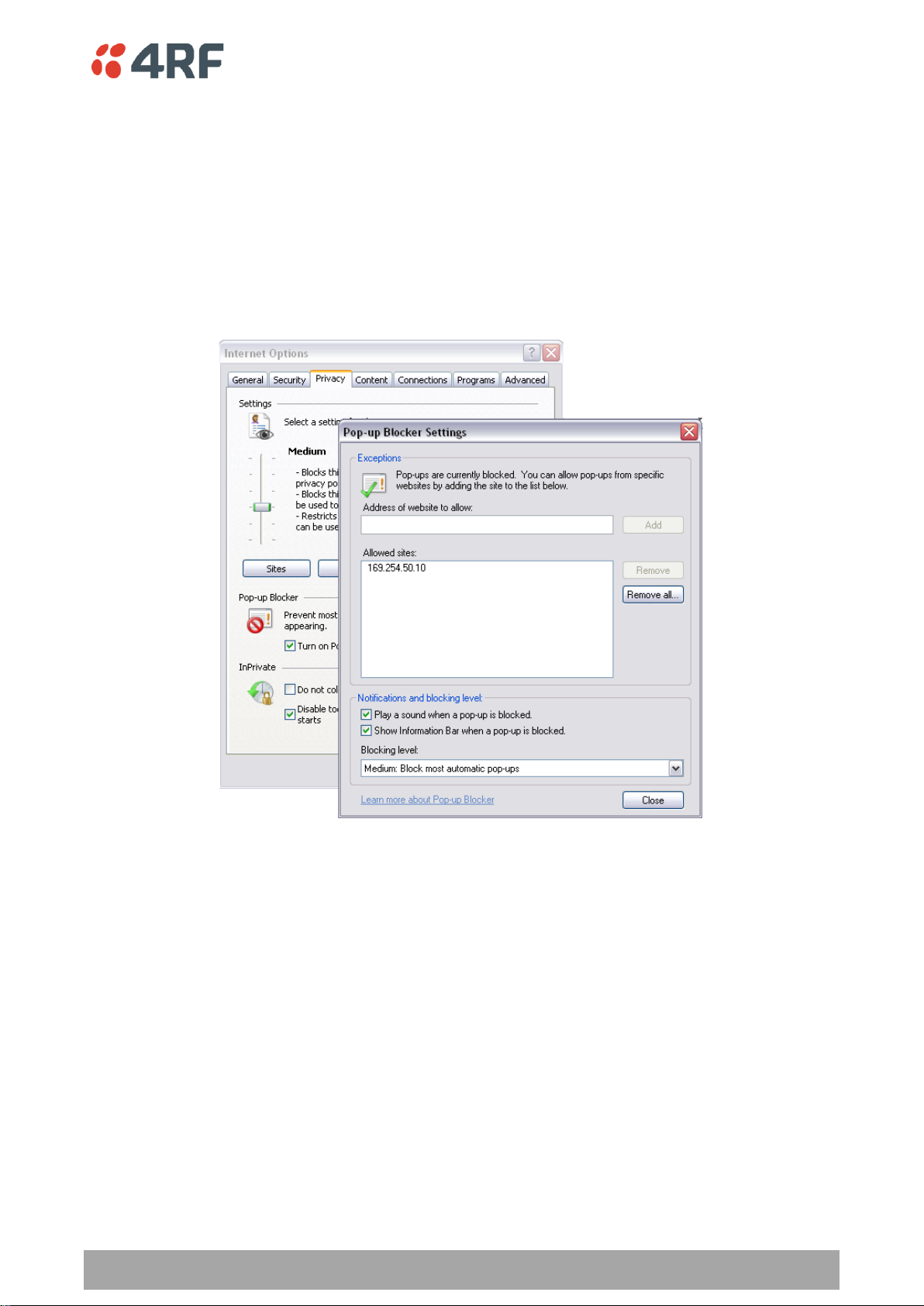
Managing the Radio | 63
Aprisa SR User Manual
To change the PC pop-up status:
Some functions within SuperVisor require Pop-ups enabled e.g. saving a MIB
Windows Internet Explorer 8 example:
1. Open Internet Explorer.
2. Open the menu item Tools > Internet Options and click on the ‘Privacy’ tab.
3. Click on ‘Pop-up Blocker Settings’.
4. Set the ‘Address of Web site to allow’ to the radio address or set the ‘Blocking Level’ to ‘Low: Allow
Pop-ups from secure sites’ and close the window.

64 | Managing the Radio
Aprisa SR User Manual
To enable JavaScript in the web browser:
Some functions within SuperVisor require JavaScript in the web browser to be enabled.
Windows Internet Explorer 8 example:
1. Open Internet Explorer.
2. Open the menu item Tools > Internet Options and click on the ‘Security’ tab.
3. Click on ‘Local Intranet’.
4. Click on ‘Custom Level’.
5. Scroll down until you see section labeled ‘Scripting’.
6. Under ‘Active Scripting’, select ‘Enable’.
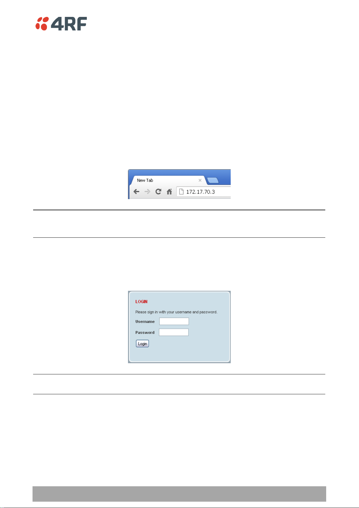
Managing the Radio | 65
Aprisa SR User Manual
Login to SuperVisor
The maximum number of concurrent users that can be logged into a radio is 6.
If SuperVisor is inactive for a period defined by the Inactivity Timeout option (see ‘Maintenance > General’
on page 125), the radio will automatically logout the user.
To login to SuperVisor:
1. Open your web browser and enter the IP address of the radio.
If you haven’t assigned an IP address to the radio, use the factory default IP address of 169.254.50.10 with
a subnet mask of 255.255.0.0.
If you don’t know the IP address of the radio, you can determine it using the Command Line Interface (see
‘Command Line Interface’ on page 202).
Note: The Aprisa SR has a Self Signed security certificate which may cause the browser to prompt a
certificate warning. It is safe to ignore the warning and continue. The valid certificate is ‘Issued By: 4RFAPRISA’ which can be viewed in the browser.
2. Login with the Username and Password assigned to you.
If unique usernames and passwords have not yet been configured, use the default username ‘admin’ and
password ‘admin’.
Important: After you login for the very first time, it is recommended that you change the default admin
password for security reasons (see ‘Changing Passwords’ on page 114).
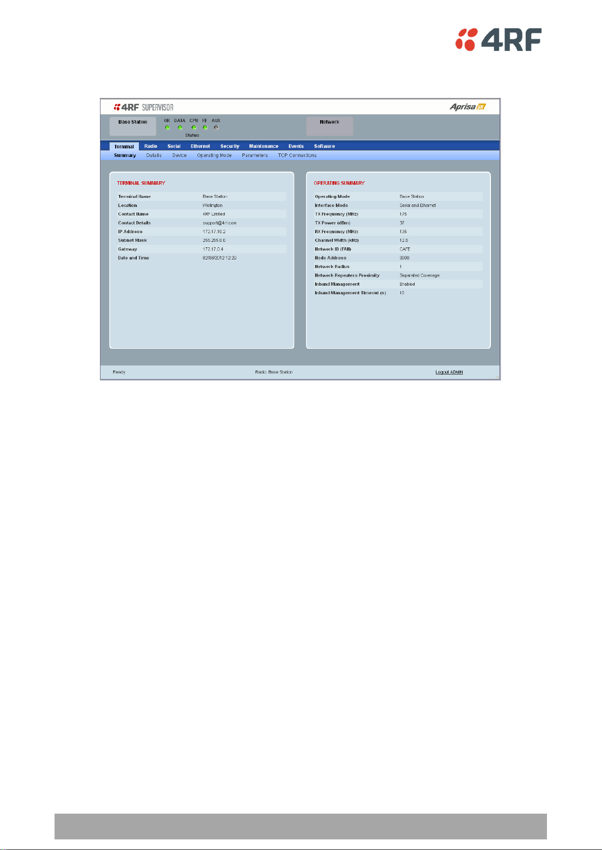
66 | Managing the Radio
Aprisa SR User Manual
If the login is successful, the opening page will be displayed.
Logout of SuperVisor
As the maximum number of concurrent users that can be logged into a radio is 6, not logging out correctly
can restrict access to the radio until after the timeout period (30 minutes).
Logging out from a radio will logout all users logged in with the same username.
If the SuperVisor window is closed without logging out, the radio will automatically log the user out after a
timeout period of 3 minutes.
To logout of SuperVisor:
Click on the ‘Logout’ button on the Summary Bar.
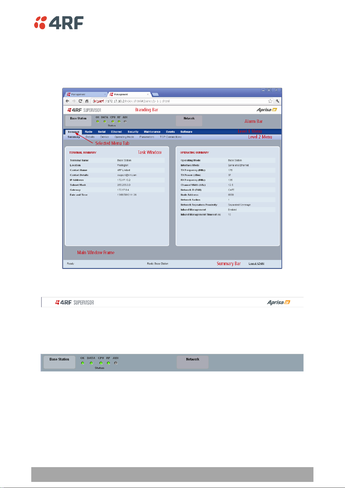
Managing the Radio | 67
Aprisa SR User Manual
SuperVisor Page Layout
Standard Radio
The following shows the components of the SuperVisor page layout for a standard radio:
SuperVisor Branding Bar
The branding bar at the top of the SuperVisor frame shows the branding of SuperVisor on the left and the
product branding on the right.
SuperVisor Alarm Bar
The alarm bar shows the name of the radio terminal that SuperVisor is logged into (the local radio) on the
left.
If the local radio is a base station, the page shows the name of the current remote / repeater station (the
remote radio) on the right. SuperVisor will manage all the repeater stations and remote stations in the
FAN.
If the local radio is a remote station or repeater station, the page shows the name of the remote /
repeater station on the left. The right side of the Alarm Bar will be blank. SuperVisor manages only the
remote / repeater station logged into.
The LED alarm indicators reflect the status of the front panel LEDs on the radio.

68 | Managing the Radio
Aprisa SR User Manual
Position
Function
Left
Busy - SuperVisor is busy retrieving data from the radio that
SuperVisor is logged into.
Ready - SuperVisor is ready to manage the radio.
Middle
Displays the name of the radio terminal that SuperVisor is currently
managing.
Right
The access level logged into SuperVisor. This label also doubles as
the SuperVisor logout button.
SuperVisor Summary Bar
The summary bar at the bottom of the page shows:
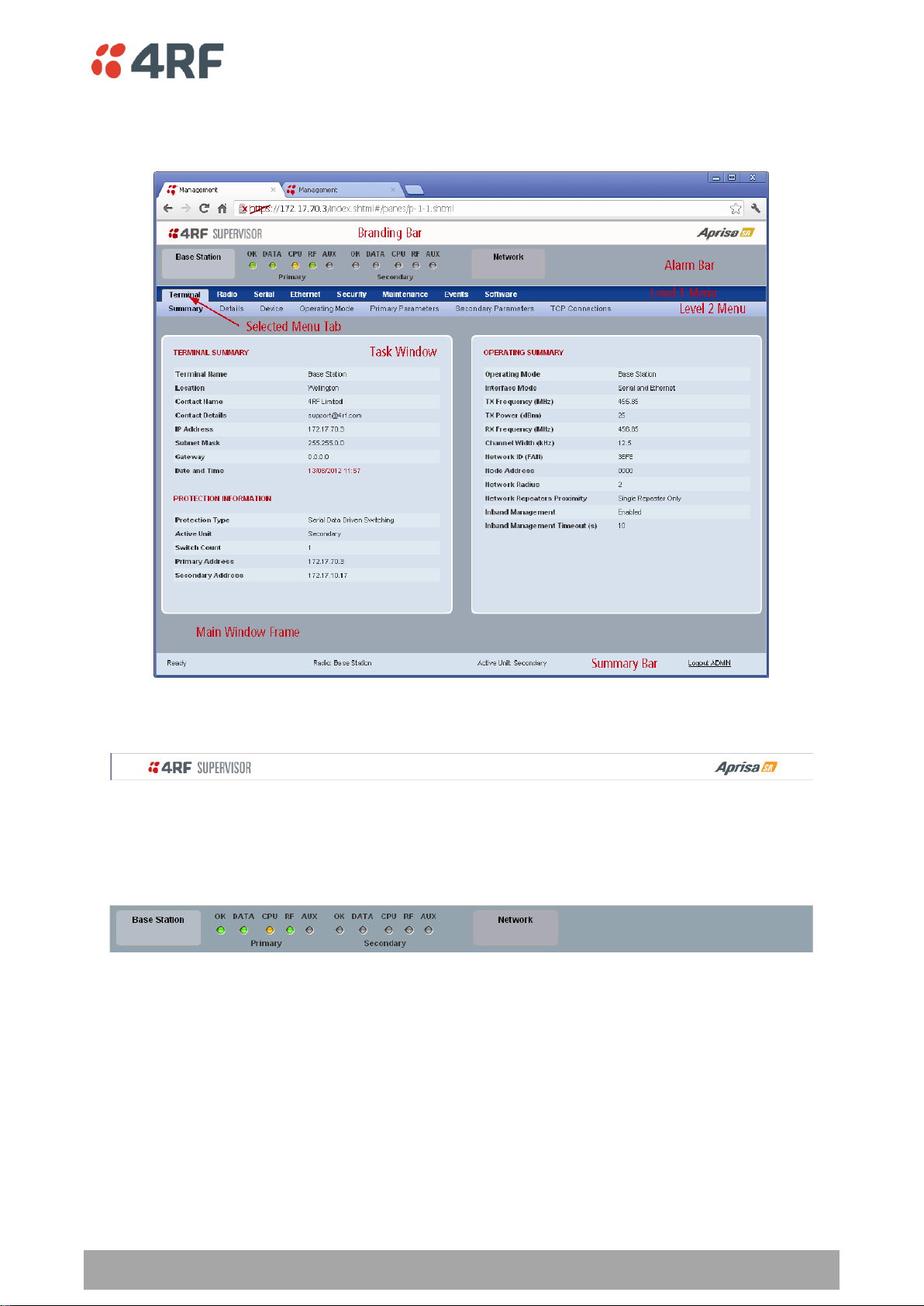
Managing the Radio | 69
Aprisa SR User Manual
Protected Station
The following shows the components of the SuperVisor page layout for a protected station:
SuperVisor Branding Bar
The branding bar at the top of the SuperVisor frame shows the branding of SuperVisor on the left and the
product branding on the right.
SuperVisor Alarm Bar
The alarm bar shows the name of the radio terminal that SuperVisor is logged into (the local radio) on the
left.
If the local radio is a base station, the page shows the name of the current remote / repeater station (the
remote radio) on the right. SuperVisor will manage all the repeater stations and remote stations in the
FAN.
If the local radio is a remote station or repeater station, the page shows the name of the remote /
repeater station on the left. The right side of the Alarm Bar will be blank. SuperVisor manages only the
remote / repeater station logged into.
The LED alarm indicators reflect the status of the front panel LEDs on the primary and secondary radios.
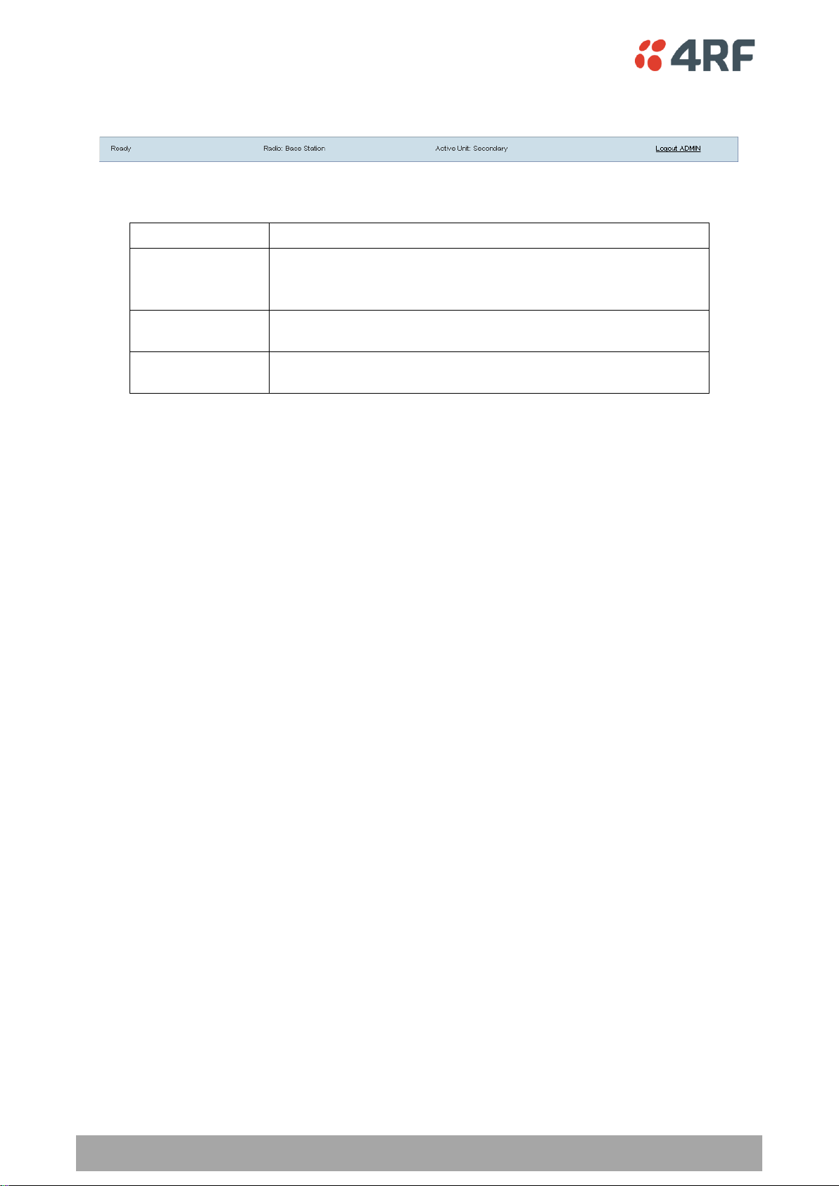
70 | Managing the Radio
Aprisa SR User Manual
Position
Function
Left
Busy - SuperVisor is busy retrieving data from the radio that
SuperVisor is logged into.
Ready - SuperVisor is ready to manage the radio.
Middle
Displays the name of the radio terminal that SuperVisor is currently
managing and the active radio.
Right
The access level logged into SuperVisor. This label also doubles as
the SuperVisor logout button.
SuperVisor Summary Bar
The summary bar at the bottom of the page shows:
Managing the Radio | 71
Aprisa SR User Manual
Local Terminal
Network
Network Table
Terminal
Summary
Radio
Exceptions
Serial
View
Ethernet
Security
Maintenance
Events
Software
SuperVisor Menu
The following is a list of SuperVisor top level menu items:
SuperVisor Parameter Settings
Changes to parameters settings have no effect until the ‘Save’ button is clicked.
Click the ‘Save’ button to apply the changes or ‘Cancel’ button to restore the current value.

72 | Managing the Radio
Aprisa SR User Manual
Menu Item
View
Technician
Engineer
Admin
Terminal > Summary
Read-Only
Read-Only
Read-Only
Read-Only
Terminal > Device Settings
No Access
Read-Write
Read-Write
Read-Write
Terminal > Operating Mode
No Access
Read-Write
Read-Write
Read-Write
Terminal > Parameters
Read-Only
Read-Only
Read-Only
Read-Only
Terminal > Primary Parameters
Read-Only
Read-Only
Read-Only
Read-Only
Terminal > Secondary Parameters
Read-Only
Read-Only
Read-Only
Read-Only
Terminal > TCP Connections
Read-Only
Read-Only
Read-Only
Read-Only
Radio > Summary
Read-Only
Read-Only
Read-Only
Read-Only
Radio > Basic
No Access
Read-Write
Read-Write
Read-Write
Radio > Channel Access
No Access
Read-Write
Read-Write
Read-Write
Serial > Summary
Read-Only
Read-Only
Read-Only
Read-Only
Serial > Port Setup
No Access
No Access
Read-Write
Read-Write
Serial > Advanced
No Access
No Access
Read-Write
Read-Write
Ethernet > Summary
Read-Only
Read-Only
Read-Only
Read-Only
Ethernet > Port Setup
No Access
Read-Write
Read-Write
Read-Write
Ethernet > Controller Setup
No Access
Read-Write
Read-Write
Read-Write
Ethernet > L2 Filtering
No Access
No Access
Read-Write
Read-Write
Ethernet > Advanced
No Access
No Access
Read-Write
Read-Write
Security > Summary
Read-Only
Read-Only
Read-Only
Read-Only
Security > Users
No Access
No Access
No Access
Read-Write
Security > Settings
No Access
No Access
Read-Write
Read-Write
Security > SNMP
No Access
No Access
No Access
Read-Write
Security > Manager
No Access
No Access
No Access
Read-Write
Security > Distribution
No Access
No Access
No Access
Read-Write
Maintenance > Summary
Read-Only
Read-Only
Read-Only
Read-Only
Maintenance > General
No Access
Read-Write
Read-Write
Read-Write
Maintenance > Test Mode
No Access
Read-Write
Read-Write
Read-Write
Maintenance > Defaults
No Access
No Access
No Access
Read-Write
Maintenance > Protection
No Access
Read-Write
Read-Write
Read-Write
Maintenance > Licence
No Access
No Access
Read-Write
Read-Write
Maintenance > Advanced
No Access
No Access
Read-Write
Read-Write
SuperVisor Menu Access
The SuperVisor menu has varying access levels dependant on the login User Privileges.
The following is a list of all possible SuperVisor menu items versus user privileges:
Terminal Settings Menu Items

Managing the Radio | 73
Aprisa SR User Manual
Events > Alarm Summary
Read-Only
Read-Only
Read-Only
Read-Only
Events > Event History
Read-Only
Read-Only
Read-Only
Read-Only
Events > Event Primary History
Read-Only
Read-Only
Read-Only
Read-Only
Events > Event Secondary History
Read-Only
Read-Only
Read-Only
Read-Only
Events > Events Setup
No Access
No Access
Read-Write
Read-Write
Events > Traps Setup
No Access
No Access
Read-Write
Read-Write
Events > Defaults
No Access
No Access
Read-Write
Read-Write
Software > Summary
Read-Only
Read-Only
Read-Only
Read-Only
Software > File Transfer
No Access
No Access
Read-Write
Read-Write
Software > File Primary Transfer
No Access
No Access
Read-Write
Read-Write
Software > File Secondary Transfer
No Access
No Access
Read-Write
Read-Write
Software > Manager
No Access
No Access
Read-Write
Read-Write
Software > Setup
No Access
No Access
Read-Write
Read-Write
Software > Remote Distribution
No Access
No Access
Read-Write
Read-Write
Software > Remote Activation
No Access
No Access
Read-Write
Read-Write
Menu Item
View
Technician
Engineer
Admin
Network Table
Read-Only
Read-Only
Read-Only
Read-Only
Summary
Read-Only
Read-Only
Read-Only
Read-Only
Exceptions
Read-Only
Read-Only
Read-Only
Read-Only
View
Read-Only
Read-Only
Read-Only
Read-Only
Network Settings Menu Items
SuperVisor Menu Items
As SuperVisor screens are dependent on the Aprisa SR configuration deployed, the following section is split
into two sections:
Standard Radio
Protected Station
All SuperVisor menu item descriptions assume full access ‘Admin’ user privileges:

74 | Managing the Radio
Aprisa SR User Manual
Standard Radio
Terminal
Terminal > Summary
TERMINAL SUMMARY
This page displays the current settings for the Terminal parameters.
OPERATING SUMMARY
Operating Mode
This parameter displays the current Operating Mode i.e. if the radio is operating as a base station,
repeater station or remote station.
Interface Mode
This parameter displays the Interfaces available for traffic on the radio (see ‘Maintenance > Licence’ on
page 131).

Managing the Radio | 75
Aprisa SR User Manual
TX Frequency (MHz)
This parameter displays the current Transmit Frequency in MHz.
TX Power (dBm)
This parameter displays the current Transmit Power in dBm.
RX Frequency (MHz)
This parameter displays the current Receive Frequency in MHz.
Channel Width (kHz)
This parameter displays the current Channel Width in kHz.
Network ID (Field Area Network)
This parameter is the network ID of this base station node and its remote / repeater stations in the FAN.
The entry is four hex chars (not case sensitive).
Node Address
The Node Address of the base station is 0000.
If the Node Address shown is FFFE, this radio is a remote station or repeater station but has not been
registered with the base station.
The base station will automatically allocate a Node Address to all its registered repeater station and
remote station radios. This address can be between 000B to 01FE.
Network Radius
This parameter displays the maximum number of hops in this network.
Network Repeaters Proximity
This parameter displays the proximity of repeaters in the FAN.
Inband Management
This parameter displays the status of the Inband Management option.
Inband Management Timeout (sec)
This parameter displays the number of seconds that the base station waits for a response from a Remote
or repeater station before aborting the Inband Management request.

76 | Managing the Radio
Aprisa SR User Manual
Terminal > Details
MANUFACTURING DETAILS
Radio Serial Number
This parameter displays the Serial Number of the radio (shown on the enclosure label).
Sub-Assembly Serial Number
This parameter displays the Serial Number of the printed circuit board assembly (shown on the PCB label).
Active Software Version
This parameter displays the version of the software currently operating the radio.

Managing the Radio | 77
Aprisa SR User Manual
Previous Software Version
This parameter displays the software version that was running on the radio prior to the current software
being activated.
A new radio from the factory will display ‘None’ for the Previous SW Version.
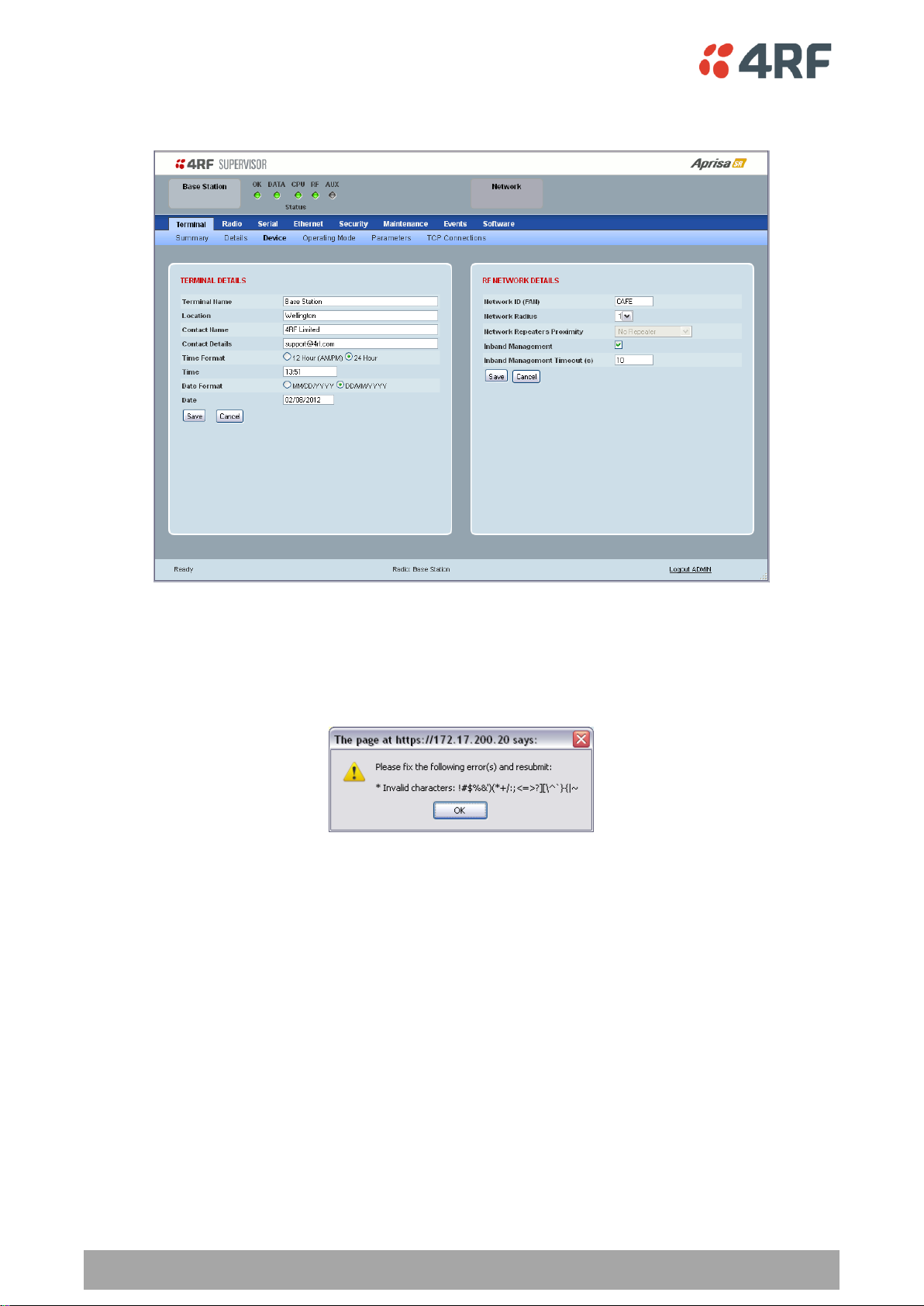
78 | Managing the Radio
Aprisa SR User Manual
Terminal > Device
TERMINAL DETAILS
The data entry in the next four fields can be up to 40 characters but cannot contain invalid characters. A
popup warns of the invalid characters:
1. Enter the Terminal Name.
2. Enter the Location of the radio.
3. Enter a Contact Name. The default value is ‘support@4RF.com’.
4. Enter the Contact Details.
5. Set the Time, Date Format and Date. This information is controlled from a software clock.

Managing the Radio | 79
Aprisa SR User Manual
Option
Function
No Repeater
No repeater in the FAN.
Single Repeater Only
Only one repeater in the FAN.
Overlapping Coverage
Multiple one hop repeaters where the remote station can see more
than one repeater.
Separated Coverage
Multiple one hop repeaters where the remote station can only see
one repeater. This option provides better network performance
than the Overlapping Coverage option.
RF NETWORK DETAILS
Network ID (FAN)
This parameter sets the network ID of this base station node and its remote / repeater stations in the FAN.
The entry is four hexadecimal chars (not case sensitive). The default setting is CAFE.
Network Radius
This parameter sets the maximum number of hops in this network e.g. if the Network Radius is set to 2, a
message from that node will only pass 2 hops before it is blocked. The default setting is 1.
All stations in the FAN should be set to the same value.
Network Repeaters Proximity
This parameter is set in base stations and repeater stations to indicate the proximity of repeaters in the
FAN. It has no affect if the Network Radius is set to 1.
The default setting is Separated Coverage.
Inband Management
This parameter sets the Inband Management option.
If the Inband Management option is enabled, SuperVisor operating on a base station can also manage all
the remote / repeater stations in the FAN.
Inband Management Timeout (sec)
This parameter sets the Inband Management timeout period. This determines the time the base station
waits for a response from a Remote or repeater station before aborting the Inband Management request.
The default setting is 10 seconds.
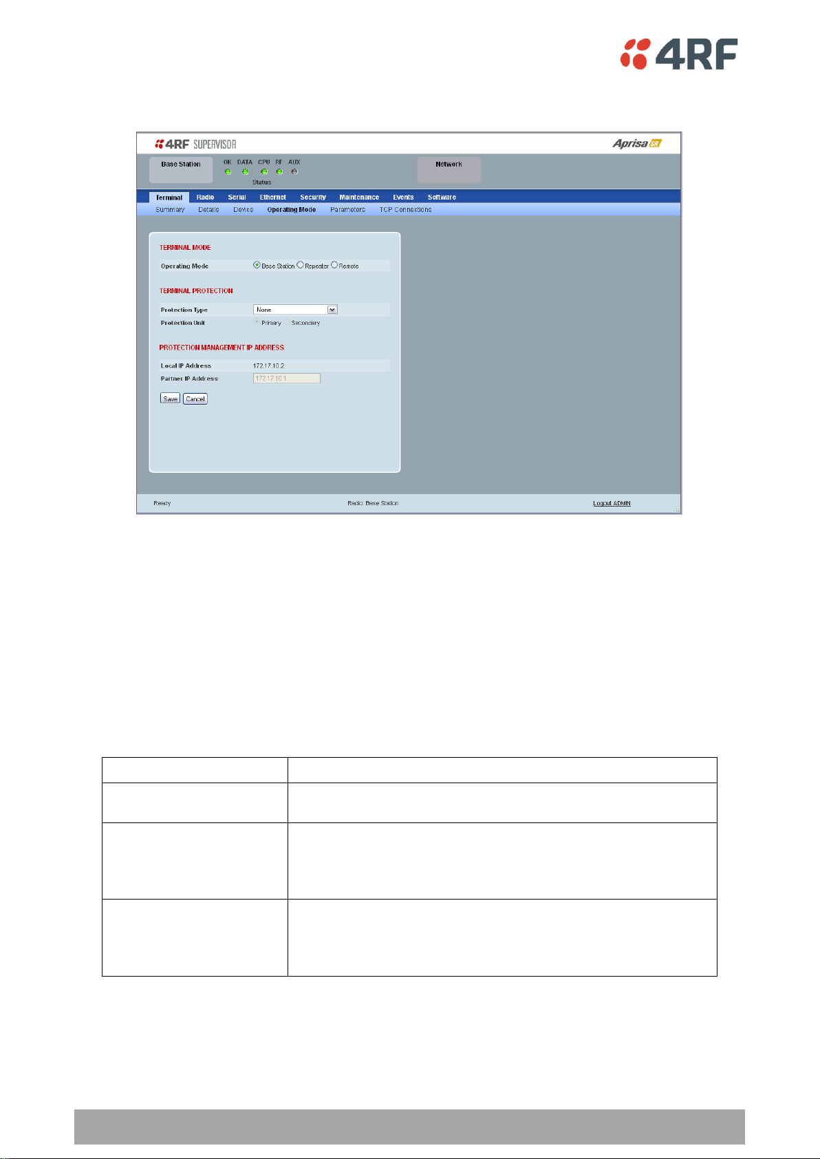
80 | Managing the Radio
Aprisa SR User Manual
Protection Type
Function
None
The SR radio is stand alone radio (not part of an Aprisa SR
Protected Station).
Redundant
(Protected Station)
Set to make this SR radio part of an Aprisa SR Protected Station.
The RF ports and interface ports from two standard Aprisa SR
Radios are switched to the standby radio if there is a failure in the
active radio
Serial Data Driven Switching
Set to make this SR radio part of an Aprisa SR Data Driven
Protected Station.
Provides radio and RS-232 serial port user interface protection for
Aprisa SR radios.
Terminal > Operating Mode
TERMINAL MODE
Operating Mode
The Operating Mode can be set to base station, repeater station or remote station. The default setting is
remote station.
TERMINAL PROTECTION
Protection Type
The Protection Type defines if a radio is a stand-alone radio or part of an Aprisa SR Protected Station. The
default setting is None.

Managing the Radio | 81
Aprisa SR User Manual
Protection Unit
The Protection Unit defines if this radio is the primary radio or secondary radio in a Protected Station.
One radio in the Protected Station is set to Primary and the other radio to Secondary.
It is recommended that radio A (the left radio) be configured as the Primary and that radio B (the right
radio) be configured as the Secondary. The default setting is Primary.
This menu item is only applicable if this radio is to become part of an Aprisa SR Protected Station.
PROTECTION MANAGEMENT IP ADDRESS
Local IP Address
The Local IP Address shows the IP address of this radio.
Partner IP Address
The Partner IP Address parameter is used to set the partner IP address if this radio is to become part of a
Protected Station.
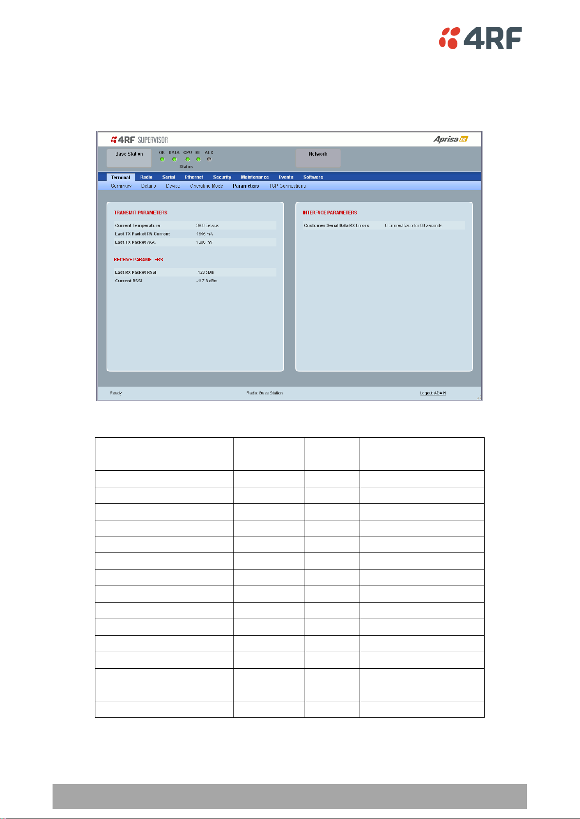
82 | Managing the Radio
Aprisa SR User Manual
Monitored Parameter
Unit
Event ID
Event Display Text
Current Temperature
Celsius
4
Temperature Threshold
Last RX Packet RSSI
dBm
7
RSSI Threshold
Last Sample RX CRC Error
Ratio
9
RX CRC Errors
Last Sample RF RX Data
Count
34
RF No Receive Data
Last Sample Eth1 RX Data
Count
10
Port 1 Eth No Receive Data
Customer Eth1 Data RX Errors
Ratio
11
Port 1 Eth Receive Errors
Customer Eth1 Data TX Errors
Ratio
12
Port 1 Eth Transmit Errors
Last Sample Eth2 RX Data
Count
35
Port 2 Eth No Receive Data
Customer Eth2 Data RX Errors
Ratio
36
Port 2 Eth Receive Errors
Customer Eth2 Data TX Errors
Ratio
37
Port 2 Eth Transmit Errors
Last Sample Serial RX Data
Count
13
Serial Data No Receive Data
Customer Serial Data RX Errors
Ratio
14
Serial Data Receive Errors
Last TX Packet PA Current
mA
None
Last TX Packet AGC
mV
None
Last TX Packet Reverse Power
dB
None
Current RSSI
dBm
None
Terminal > Parameters
The Parameters page is a dynamic page that will display the parameters associated with the active
alarms, set on ‘Events > Events Setup’ on page 137. The screenshot below shows a small amount of
monitored alarms as an example.
The following is a list of alarm events that are monitored:
If an associated alarm event occurs, the Parameters table will display the current value for that
parameter. The refresh time is 12 seconds.
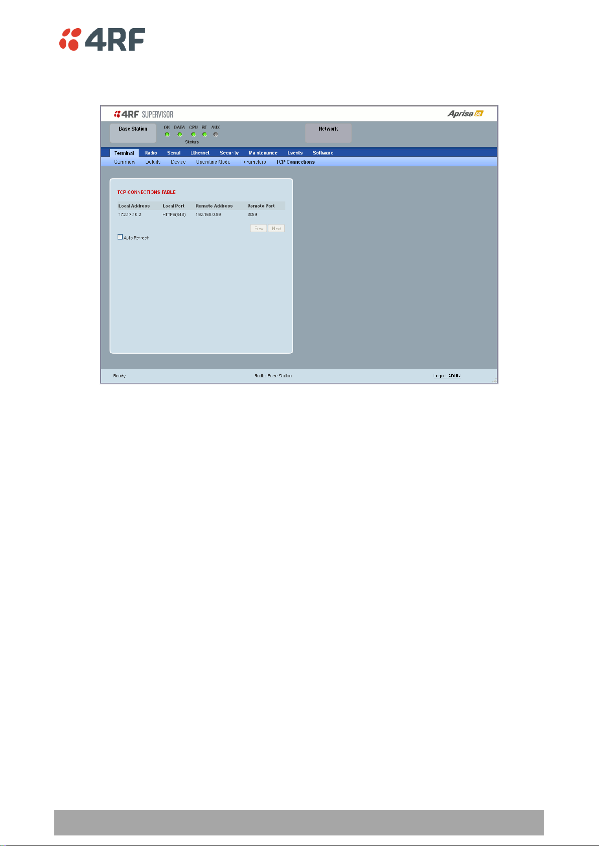
Managing the Radio | 83
Aprisa SR User Manual
Terminal > TCP Connections
The TCP Connections page displays the list of active TCP connections on the radio.
TCP CONNECTIONS TABLE
The Next button will display the next page of 8 connections and the Prev button will display the previous
page of 8 connections.
If the Auto Refresh option is ticked, the TCP Connections table will refresh every 12 seconds.
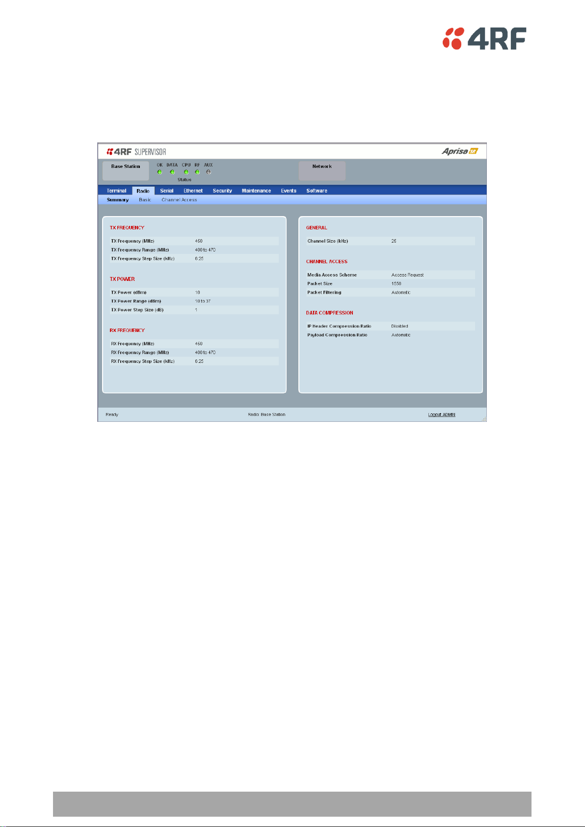
84 | Managing the Radio
Aprisa SR User Manual
Radio
Radio > Summary
This page displays the current settings for the Radio parameters.
See ‘Radio > Basic’ and ‘Radio > Channel Access’ for setting details.
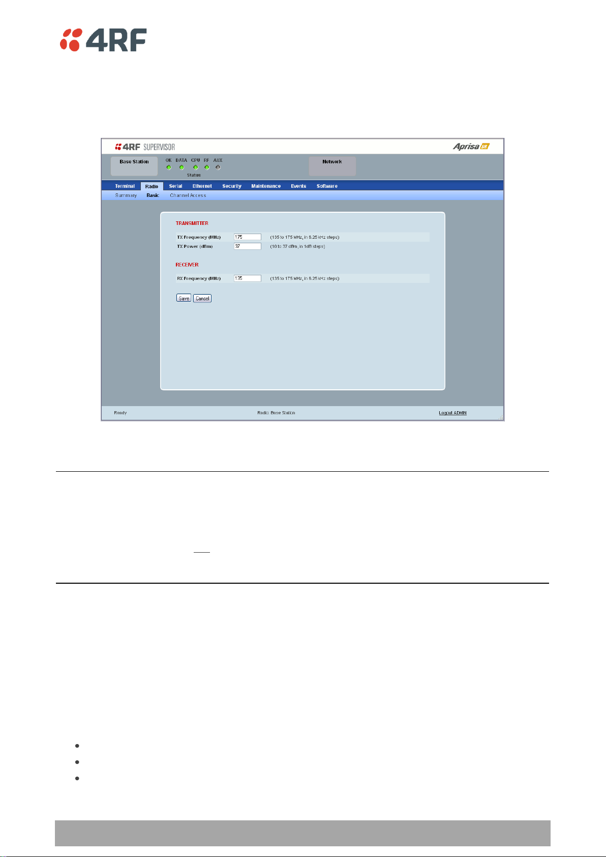
Managing the Radio | 85
Aprisa SR User Manual
Radio > Basic
Transmit frequency, transmit power and channel size would normally be defined by a local regulatory
body and licensed to a particular user. Refer to your site license details when setting these fields.
TRANSMITTER / RECEIVER
Important:
1. Changing the remote / repeater station frequencies will disable all management communication to the
remote / repeater stations but then by changing the base station to match the remote / repeater stations,
the radio links will be restored as will the management communication.
2. Enter the TX frequency and the RX frequency and then click ‘Save’. This is to prevent remote
management communication from being lost before both frequencies have been changed in the remote
stations.
TX and RX Frequencies.
The TX and RX frequencies entered must be within the frequency tuning range of the product frequency
band (see ‘Frequency Bands’ on page 220).
If the frequency entered is not resolvable to the synthesizer step size for the frequency band it is
rejected. For example; a 400 MHz radio has a synthesizer step size of 6.250 kHz.
The default setting is 330 MHz for a UHF radio and 136 MHz for VHF radio.
The TX and RX frequencies can be single frequency ½ duplex or dual frequency ½ duplex. Dual frequency
½ duplex is often used for reasons of:
Channel Planning
Network Efficiencies
Regulatory rules
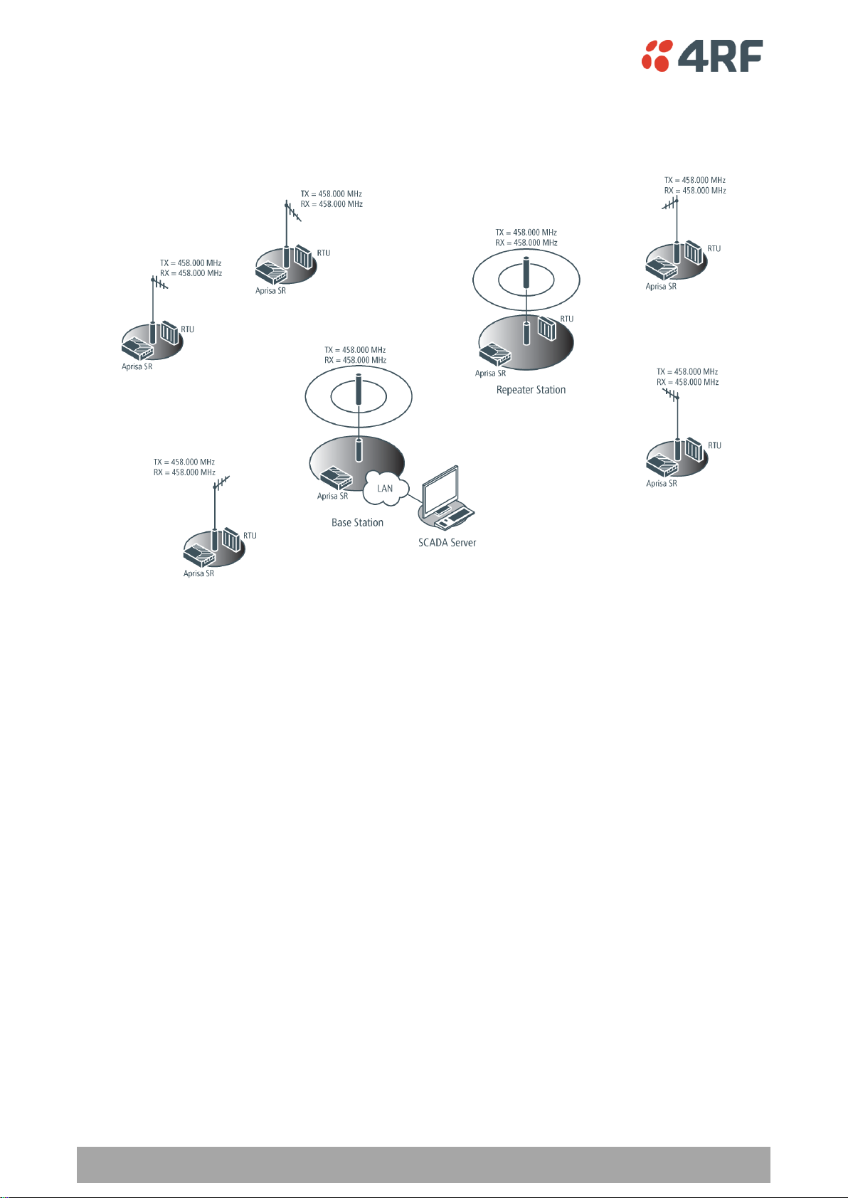
86 | Managing the Radio
Aprisa SR User Manual
Single Frequency Operation
The TX and RX frequencies of the base station, repeater station and all the remote stations are on the
same frequency.
To change the TX and RX frequencies:
1. Change the TX and RX frequencies of the remote stations operating from the repeater station to the
new frequency. The radio links to these remote stations will fail.
2. Change the TX and RX frequencies of the repeater station operating from the base station to the new
frequency. The radio links to the repeater station and its remote stations will fail.
3. Change the TX and RX frequencies of the remote stations operating from the base station to the new
frequency. The radio links to these remote stations will fail.
4. Change the TX and RX frequencies of the base station to the new frequency. The radio links to all
stations will restore.
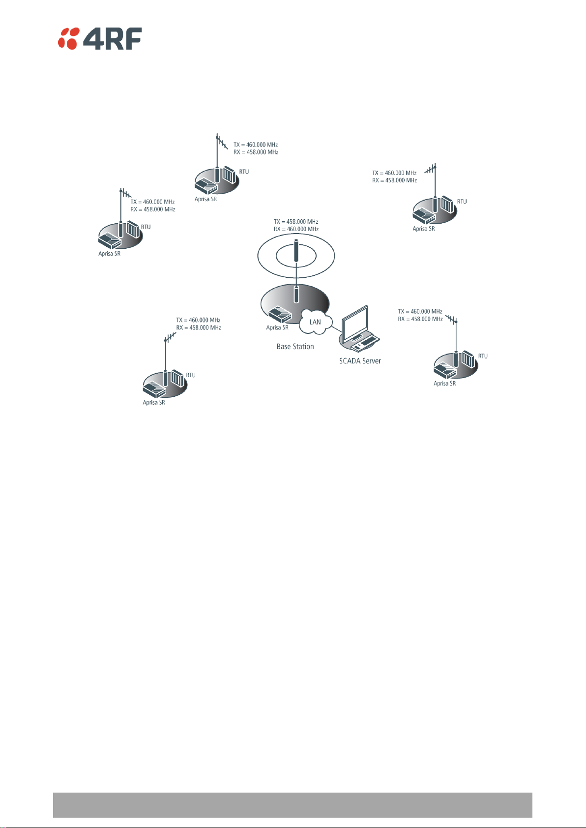
Managing the Radio | 87
Aprisa SR User Manual
Dual Frequency No Repeater
The TX frequency of all the remote stations matches the RX frequency of the base station.
The RX frequency of all the remote stations matches the TX frequency of the base station.
To change the TX and RX frequencies:
1. For all the remote stations, change the RX frequency to frequency A and the TX frequency to
frequency B. The radio links to the remote stations will fail.
2. For the base station, change the TX frequency to frequency A and the RX frequency to frequency B.
The radio links to the remote stations will restore.

88 | Managing the Radio
Aprisa SR User Manual
Dual Frequency with Repeater
The TX frequency of the remote stations associated with the base station matches the RX frequency of the
base station.
The TX frequency of the repeater station associated with the base station matches the RX frequency of
the base station.
The TX frequency of the remote stations associated with the repeater station matches the RX frequency of
the repeater station.
The RX frequency of the remote stations associated with the base station matches the TX frequency of the
base station.
The RX frequency of the repeater station associated with the base station matches the TX frequency of
the base station.
The RX frequency of the remote stations associated with the repeater station matches the TX frequency of
the repeater station.
To change the TX and RX frequencies:
1. For all the remote stations operating from the repeater station, change the RX frequency to frequency
A and the TX frequency to frequency B. The radio links to these remote stations will fail.
2. For the repeater station, change the TX frequency to frequency A and the RX frequency to frequency
B.
3. For the base station, change the RX frequency to frequency A and the TX frequency to frequency B.
The radio links to the remote stations operating from the repeater station will restore.
4. For all the remote stations operating from the base station, change the TX frequency to frequency A
and the RX frequency to frequency B.

Managing the Radio | 89
Aprisa SR User Manual
TX Power
The transmitter power is the power measured at the antenna output port when transmitting. The
transmitter power has a direct impact on the radio power consumption (see ‘Power Consumption’ on page
225) and ‘Save’ the change.
The default setting is +37 dBm.
Note: The Aprisa SR transmitter contains power amplifier protection which allows the antenna to be
disconnected from the antenna port without product damage.

90 | Managing the Radio
Aprisa SR User Manual
Access Mode
Function
Access Request
Channel access scheme where the base stations controls the
communication on the channel. Remotes ask for access to the
channel, and the base station grants access if the channel is not
occupied.
This mode is a general purpose access method for high and low
load networks.
Listen Before Send
Channel access scheme where network elements listen to ensure
the channel is clear, before trying to access the channel.
This mode is optimised for low load networks and repeated
networks.
Radio > Channel Access
CHANNEL ACCESS
Access Mode
This parameter sets the Media Access Control (MAC) used by the radio for over the air communication.
The default setting is Access Request.

Managing the Radio | 91
Aprisa SR User Manual
Packet Size (Bytes)
This parameter sets the maximum over-the-air packet size in bytes. A smaller maximum Packet Size is
beneficial when many remote stations or repeater stations are trying to access the channel. The default
setting is 1550 bytes.
As radios dispatched from the factory have a Packet Size set to the maximum value of 1550 bytes, if a new
radio is installed in an existing Field Access Network (FAN), the Packet Size must be changed to ensure it
is the same value for all radios in the FAN. The new radio will not register an existing FAN if the Packet
Size is not the same as the other radios in the FAN.
This packet size includes the wireless protocol header and security payload (0 to 16 bytes). The length of
the security header depends on the level of security selected.
When the security setting is 0, the maximum user data transfer over-the-air is 1516 bytes.
When encryption is enabled, the entire packet of user data (payload) is encrypted. If authentication is
being used, the security frame will be added (up to 16 bytes). The wireless protocol header is then added
which is proprietary to the Aprisa SR. This is not encrypted.
Packet Time to Live (ms)
This Time To Live (TTL) parameter sets the time a packet is allowed to live in the system before being
dropped if it cannot be transmitted over the air. It is used to prevent old, redundant packets being
transmitted through the Aprisa SR network. The default setting is 1500 ms.
In the case of serial poll SCADA networks such as MODBUS and IEC 60870.50.101, it is important to ensure
the replies from the RTU are in the correct sequence and are not timed out replies from Master requests.
If the TTL value is too long, the SCADA master will detect sequence errors.
It is recommended to use a TTL which is half the serial SCADA timeout. This is commonly called the ‘scan
timeout’ or ‘link layer time out’ or ‘retry timeout’.
When using TCP protocols, a TTL of 1500 ms is recommended because a TCP re-transmission usually occurs
after approximately 3 second.
In SCADA networks which use both serial and Ethernet, it is recommended that the TTL is set to half the
serial SCADA timeout for serial remotes, and 1500 ms for Ethernet (TCP) remotes. For example, if the
serial SCADA timeout is 1000 ms, a remote radio which is connected to the serial RTU should be set to
500 ms, a remote radio which is connected to a Ethernet (TCP) RTU should have a 1500 ms timeout.
In this case, the base station TTL should be set to 1500 ms as well; or which ever is the longer TTL of
serial or Ethernet.

92 | Managing the Radio
Aprisa SR User Manual
Access Mode
Function
Disabled
Every packet received by the radio will be forwarded to the
relevant interface.
Automatic
The radio will filter (discard) packets not destined for itself
according to the Aprisa SR traffic protocols
Packet Filtering
Each Aprisa SR radio can filter packets not destined for itself. The Packet Filtering parameter controls this
functionality.
In an Aprisa SR network, all communication from remote stations is destined for the base station in the
Aprisa SR network communication protocol. In a repeater network, a remote station will send a message
to the base station. The repeater station will receive this and then repeat the message. The repeated
message will then be received by the base station. Other remote stations connected to the repeater
station will receive this message and depending on the Packet Filtering parameter, either forward this
packet or discard it.
This filtering capability can provide the ability for remote stations to communicate with each other when
connected to a repeater, particularly useful in the event of losing communication with a SCADA Master,
assuming the Aprisa SR network is still operational.
Note: IP Header Compression must be disabled for this feature to operate correctly (see ‘IP Header
Compression Ratio’ on page 93).
The default setting is Automatic.
Note: The Aprisa SR network is transparent to the protocol being transmitted; therefore the Packet
Filtering parameter is based on the Aprisa SR addressing and network protocols, not the user (SCADA, etc.)
traffic protocols.

Managing the Radio | 93
Aprisa SR User Manual
IP Header
Compression Ratio
Function
Compression
Disabled
Disables IP Header Compression.
High
State information is synchronized less frequently thus achieving
the best compression ratio.
Medium
State information is synchronization less frequently than ‘High’
setting but more frequently than ‘Low’ setting.
Low
State information is synchronized frequently thus reducing the
compression ratio.
LISTEN BEFORE SEND
When the Access Mode is set for Listen Before Send, the Listen Before Send parameters can be set:
ACK
This parameter determines if unicast requests from the remote station are acknowledged by the base
station. Receiving acknowledgments increases reliability of transport but reduces available channel
capacity so if application has the capability to handle lost or duplicate messages, the ACK should be
disabled.
When enabled, the transmitter requests an ACK to ensure that the transmission has been successful. If the
transmitter does not receive an ACK, then random back-offs are used to reschedule the next transmission.
The default setting is enabled.
DATA COMPRESSION
IP Header Compression Ratio
The IP Header Compression implements TCP/IP ROHC v2 (Robust Header Compression v2. RFC4995,
RFC5225, RFC4996) to compress the IP header.
IP Header compression module comprises of two main components, Compressor and Decompressor. Both
these components maintain some state information for an IP flow to achieve header compression.
However, for reasons like packet drops or station reboots this state information can go out of sync
between compressor and decompressor resulting in compression and/or decompression failure resulting in
loss of packets.
The Compression Ratio controls the rate at which compressor and decompressor synchronize state
information with each other. Frequent synchronization results in reduced ratio.
The default setting is High.
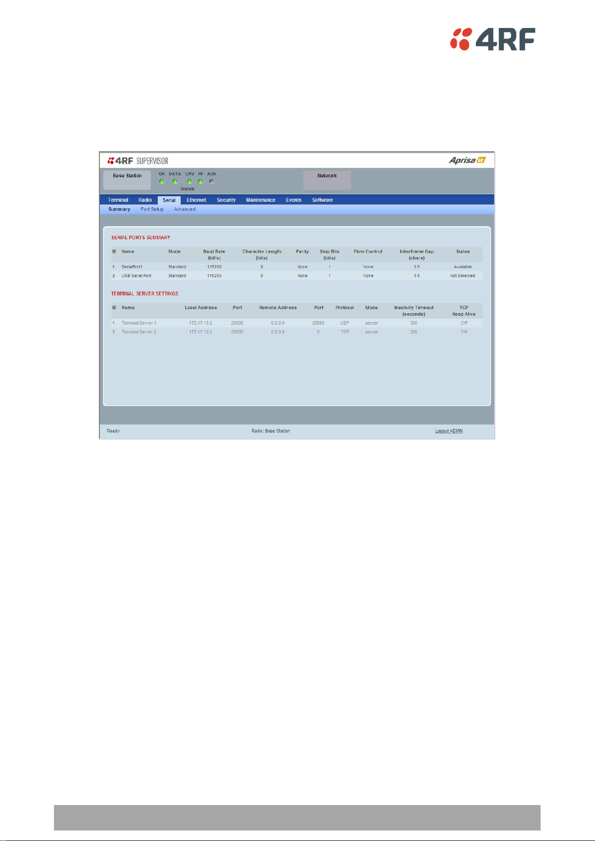
94 | Managing the Radio
Aprisa SR User Manual
Serial
Serial > Summary
This page displays the current settings for the serial port parameters.
See ‘Serial > Port Setup’ on page 95 for configuration options.
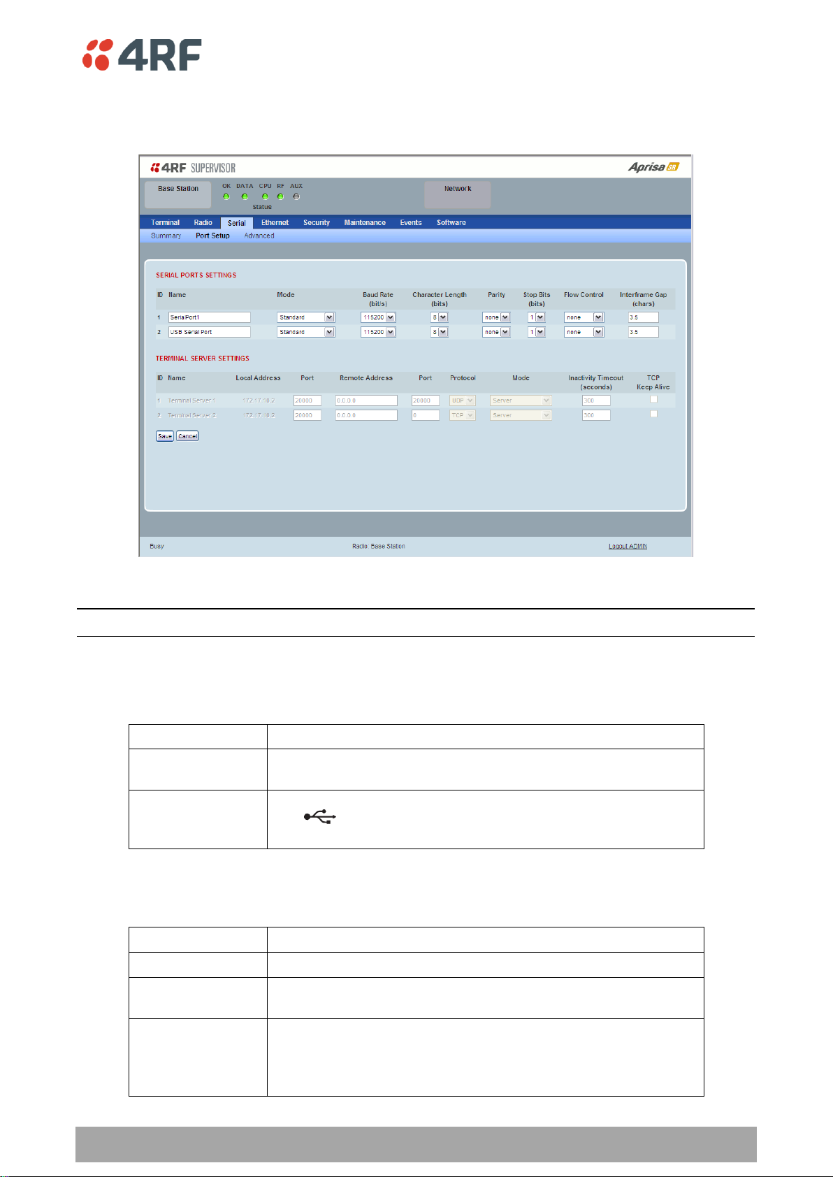
Managing the Radio | 95
Aprisa SR User Manual
Name
Function
SerialPort1
This is the normal RS-232 serial port provided with the RJ45
connector.
USB Serial Port
This is the additional RS-232 serial port provided with the USB Host
Port connector with a USB to RS-232 RJ45 converter cable
(see ‘USB RS-232 Serial Port’ on page 40).
Mode
Function
Disabled
The serial port is not required.
Standard
The serial port is communicating with serial ports on other
stations.
Terminal Server
A base station Ethernet port can communicate with both Ethernet
ports and serial ports on remote stations.
RS-232 traffic is encapsulated in IP packets (see ‘Serial > Port
Setup’ TERMINAL SERVER SETTINGS on page 97).
Serial > Port Setup
This page provides the setup for the serial port settings.
SERIAL PORTS SETTINGS
Note: The current Aprisa SR has one serial port so there will be only one record.
Name
This parameter sets the port name which can be up to 32 characters.
Mode
This parameter defines the mode of operation of the serial port. The default setting is Standard.
96 | Managing the Radio
Aprisa SR User Manual
Flow Control
Function
None
The Aprisa SR radio port (DCE) CTS is in a permanent ON (+ve)
state.
This does not go to OFF if the radio link fails.
CTS-RTS
CTS / RTS hardware flow control between the DTE and the Aprisa
SR radio port (DCE) is enabled.
If the Aprisa SR buffer is full, the CTS goes OFF.
In the case of radio link failure the signal goes to OFF (-ve) state.
Baud Rate (bit/s)
This parameter sets the baud rate to 300, 1200, 2400, 4800, 9600, 19200, 38400, 57600 or 115200 bit/s.
The default setting is 115200 bit/s.
Character Length (bits)
This parameter sets the character length to 7 or 8 bits. The default setting is 8 bits.
Parity
This parameter sets the parity to Even, Odd or None. The default setting is None.
Stop Bits (bits)
This parameter sets the number of stop bits to 1 or 2 bits. The default setting is 1 bit.
Flow Control
This parameter sets the flow control of the serial port. The default setting is Disabled.
Inter-Frame Gap (chars)
This parameter defines the gap between successive serial data frames. It is used to delimit the serial data
to define the end of a packet. The Inter-Frame Gap limits are 0.5 to 16 chars. The default setting is 3.5
chars.
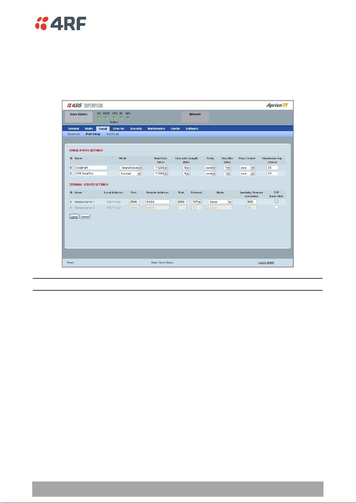
Managing the Radio | 97
Aprisa SR User Manual
TERMINAL SERVER SETTINGS
This menu item is only applicable if the serial port has an operating mode of Terminal Server.
The Terminal Server operating mode provides encapsulation of serial data into an IP packet (TCP or UDP).
A server connected to a base station Ethernet port can communicate with all remote station Ethernet
ports and serial ports.
Note: The current Aprisa SR has one serial port so there will be only one record.
Local Address
This parameter displays the IP address of this radio.
Port
This parameter sets the port number of the local serial port.
The valid port number range is greater than or equal to 1024 and less than or equal to 49151 but with
exclusions of 0, 5445, 6445, 9930 or 9931. The default setting is 20000.
Remote Address
This parameter sets the IP address of the server connected to the base station Ethernet port.
Port
This parameter sets the port number of the server connected to the base station Ethernet port. The
default setting is 0.
Protocol
This parameter sets the IP protocol used for terminal server operation. The default setting is TCP.

98 | Managing the Radio
Aprisa SR User Manual
Mode
Function
Client
The radio will attempt to establish a TCP connection with the
specified remote unit.
Server
The radio will listen for a TCP connection on the specified local
port.
Data received from any client shall be forwarded to the associated
serial port while data received from that serial port shall be
forwarded to every client with an open TCP connection.
If no existing TCP connections exist, all data received from the
associated serial port shall be discarded.
Client and Server
The radio will listen for a TCP connection on the specified local
port and if necessary, establish a TCP connection with the
specified remote unit.
Data received from any client shall be forwarded to the associated
serial port while data received from that serial port shall be
forwarded to every client with an open TCP connection.
Mode
This parameter defines the mode of operation of the terminal server connection. The default setting is
Client and Server.
Inactivity Timeout (seconds)
This specifies the duration (in seconds) to automatically terminate the connection with the remote TCP
server if no data has been received from either the remote TCP server or its associated serial port for the
duration of the configured inactivity time.
TCP Keep Alive
A TCP keepalive is a message sent by one device to another to check that the link between the two is
operating, or to prevent the link from being broken.
If the TCP Keep Alive is enabled, the radio will be notified if the TCP connection fails.
If the TCP Keep Alive is disabled, the radio relies on the Inactivity Timeout to detect a TCP connection
failure. The default setting is disabled.
Note: An active TCP Keep Alive will generate a small amount of extra network traffic.
 Loading...