


160 | Managing the Radio
Aprisa SR+ User Manual 1.6.0 PO
QoS
QoS > Summary
This page provides a summary of the QoS Settings.
See ‘QoS > Traffic Priority’ and ‘QoS > Traffic Classification’ for configuration options.

Managing the Radio | 161
Aprisa SR+ User Manual 1.6.0 PO
QoS > Traffic Priority
TRAFFIC PRIORITY
Default Management Data Priority
The Default Management Data Priority controls the priority of the Ethernet management traffic relative to
Ethernet customer traffic. It can be set to Very High, High, Medium and Low. The default setting is
Medium.
This priority is also used for traffic if the remote serial port is not available for the radio hardware data
port option e.g. if the base station is 2E2S and a remote radio is 4E0S.
SERIAL PRIORITY
This parameter controls the per port priority of the serial customer traffic relative to the Ethernet
customer traffic. If equal priority is required to Ethernet traffic, this setting must be the same as the
Ethernet Data Priority setting.
The serial data priority can be set to Very High, High, Medium and Low. The default setting is Low.
A queuing system is used to prioritize traffic from the serial and Ethernet interfaces for over the air
transmission. A weighting may be given to each data type and this is used to schedule the next
transmission over the air e.g. if there are pending data packets in multiple buffers but serial data has a
higher weighting it will be transmitted first. The serial buffer is 20 serial packets (1 packet can be up to
512 bytes).
There are four priority queues in the Aprisa SR: Very High, High, Medium and Low. Data is added to one of
these queues depending on the priority setting. Data leaves the queues from highest priority to lowest:
the Very High queue is emptied first, followed by High then Medium and finally Low.

162 | Managing the Radio
Aprisa SR+ User Manual 1.6.0 PO
ETHERNET PRIORITY
This parameter controls the per port priority of the Ethernet customer traffic relative to the serial
customer traffic. If equal priority is required to serial traffic, this setting must be the same as the Serial
Data Priority setting.
The Ethernet Priority enables users to set the priority of Ethernet port ingress frames. The priority for
each port can be:
1. From PCP priority bits (VLAN priority) in VLAN tagged frames or priority tag (VLAN 0) frames
2. From DSCP priority bits in an IP packet (DSCP in IPv4 TOS field)
3. All frames are set to ‘very high’ priority
4. All frames are set to ‘high’ priority
5. All frames are set to ‘medium’ priority
6. All frames are set to ‘low’ priority
The default setting is Low.
A queuing system is used to prioritize customer traffic from the serial and Ethernet interfaces for over the
air transmission. A weighting may be given to each data type and this is used to schedule the next
transmission over the air e.g. if there are pending data packets in multiple buffers but serial data has a
higher weighting it will be transmitted first. The Ethernet buffer is 10 Ethernet packets (1 packet can be
up to Ethernet MTU, 1536 bytes).
There are four priority queues in the Aprisa SR+: Very High, High, Medium and Low. Data is added to one
of these queues depending on the priority setting. Data leaves the queues from highest priority to lowest:
the Very High queue is emptied first, followed by High then Medium and finally Low.
Default Priority
When the priority of an Ethernet port uses the PCP bits (VLAN priority) values the ‘Default Priority’ option
is enabled, allowing the priority of untagged VLAN frames to be set.
When the priority of an Ethernet port uses the DSCP priority (in IPv4 TOS field) values the ‘Default
Priority’ option is enabled, allowing the priority of ARP frames to be set.

Managing the Radio | 163
Aprisa SR+ User Manual 1.6.0 PO
PRIORITY DEFINITIONS
PCP (Priority Code Point)
These settings provide priority translation / mapping between the external radio LAN VLAN priority
network and the radio internal VLAN priority network, using the VLAN tagged PCP (Priority Code Point)
priority field in the Ethernet/VLAN frame.
The IEEE 802.1Q specification defines a standards-based mechanism for providing VLAN tagging and class
of service (CoS) across Ethernet networks. This is accomplished through an additional VLAN tag, which
carries VLAN tag ID and frame prioritization information (PCP field), inserted within the header of a Layer
2 Ethernet frame.
Priority Code Point (PCP) is a 3-bit field that indicates the frame priority level (or CoS). The operation of
the PCP field is defined within the IEEE 802.1p standard, which is an extension of 802.1Q. The standard
establishes eight levels of priority, referred to as CoS values, where CoS 7 (‘111’ in PCP filed) is the
highest priority and CoS 0 (‘000’) is the lowest priority.
The radio in bridge mode used the PCP value in the VLAN tag to prioritize packets and provide the
appropriate QoS treatment per traffic type. The radio implements 4 priority queuing techniques that base
its QoS on the VLAN priority (PCP). Based on VLAN priority bits, traffic can be put into a particular Class of
Service (CoS) queue. Packets with higher CoS will always serve first for OTA transfer and on ingress/egress
Ethernet ports.
The ‘PCP priority definition’ tab is used to map ingress VLAN packet with PCP priority to the radio internal
CoS (priority). Since, in most of the cases the radio VLAN network is connected to the corporate VLAN
networks, the network administrator might like to have a different VLAN priority scheme of the radio
network CoS. For example, management traffic in the multi-gigabit corporate VLAN network might be
prioritize with priority 7 (highest priority) and SCADA traffic with priority 5, but in the narrow bandwidth
radio network, SCADA traffic will be map to radio very high CoS / priority (i.e. set PCP 5 = Very high) and
management traffic might will be map to radio medium CoS / priority (i.e. set PCP 7 = medium) in order
to serve first the mission-critical SCADA traffic over the radio network.

164 | Managing the Radio
Aprisa SR+ User Manual 1.6.0 PO
This is done by mapping the external radio network VLAN priority to the internal radio CoS / priority using
the ‘PCP priority definition’ tab. The radio support 4 queues, thus at maximum an 8 -> 4 VLAN priority /
CoS mapping is done.
Default mapping of ingress packet VLAN priority to radio CoS / priority shown in the ‘PCP priority
definition’ tab.

Managing the Radio | 165
Aprisa SR+ User Manual 1.6.0 PO
DSCP (Differentiated Services Code Point)
These settings provide translation / mapping between the external radio IP priority network and the radio
internal IP priority network, using the DSCP (DiffServ Code Point) priority field in the IP packet header.
Differentiated Services (DiffServ) is a new model in which traffic is treated by routers with relative
priorities based on the IPv4 type of services (ToS) field. DSCP (DiffServ Code Point) standard defined in
RFC 2474 and RFC 2475. DiffServ increases the number of definable priority levels by reallocating bits of
an IP packet for priority marking.
The DiffServ architecture defines the DiffServ (DS) field, which supersedes the ToS field in IPv4 to make
per-hop behaviour (PHB) decisions about packet classification and traffic scheduling functions. The six
most significant bits of the DiffServ field (in the IPv4 TOS field) is called as the DSCP. The standardized
DiffServ field of the packet is marked with a value so that the packet receives a particular
routing/forwarding treatment or PHB, at each router node. Using DSCP packet classification, traffic can be
partition into multiple priority levels.
The radio in router mode uses the DSCP value in the IP header to select a PHB behaviour for the packet
and provide the appropriate QoS treatment. The radio implements 4 priority queuing techniques that base
its PHB on the DSCP in the IP header of a packet. Based on DSCP, traffic can be put into a particular
priority / CoS (Class of Service) queue. Packets with higher CoS will always serve first for OTA transfer and
on ingress / egress Ethernet ports.
The ‘DSCP priority definition’ tab is used to map ingress IP packet with DSCP priority to the radio internal
priority / CoS. Since, in most of the cases the radio routed network is connected to the corporate routed
networks, the network administrator might like to have a different routed network priority scheme of the
radio network, for example management traffic in the multi-gigabit corporate routed network might be
prioritize with DSCP EF (expedite forwarding) code (DSCP highest priority), and SCADA traffic with DSCP
AF11 (assured forwarding) code (high priority), but in the narrow bandwidth radio network, SCADA traffic
will be map to radio very high CoS / priority (i.e. set AF11 = Very high) and management traffic might map
to radio low CoS / priority (i.e. set EF = Low) in order to serve first the mission-critical SCADA traffic over
the radio network.

166 | Managing the Radio
Aprisa SR+ User Manual 1.6.0 PO
This is done by mapping the external radio network DSCP priority to the internal radio CoS / priority levels
using the ‘DSCP priority definition’ tab. The radio support four queues, thus at maximum a 64 -> 4 CoS /
priority mapping is done.
Default mapping of ingress packet DSCP priority to radio CoS shown in the ‘DSCP priority definition’ tab.
The radio maps all 64 DSCP values. The user can configure most common used 21 DSCP codes and the rest
are mapped by default to low CoS / priority.

Managing the Radio | 167
Aprisa SR+ User Manual 1.6.0 PO
QoS > Traffic Classification
These settings provide multiple traffic classification profiles based on classification rules. Profiles for a
specific traffic type, protocol or application can be assigned to a particular VLAN and CoS / priority in
bridge mode or to CoS / priority in router mode to provide the appropriate QoS treatment.
For example SCADA traffic, management traffic, FTP traffic, can each have its own profile build with a set
of classification rules. A profile can be build using multiple classification rules based on ports, Ethernet,
IP, TCP / UDP headers fields (i.e. L1/2/3/4 header fields) such as: Ethernet port #1, VLAN ID, VLAN
priority, IP DSCP Priority, MAC/IP address, TCP / UDP port fields to identify and classify the specific traffic
type. When an ingress packet matches the profile L2/3/4 header fields settings, the packet is assigned to
a particular VLAN and CoS / priority in bridge mode or to CoS / priority in router mode to provide the
appropriate QoS treatment.
The radio supports four CoS / priority queues: very high, high, medium and low. These queues are
connected to a strict priority scheduler which dispatches packets from the queues out to the egress port
by always serving first the ‘very high’ priority queue, whenever there is a packet in this queue. When the
highest priority queue empties, the scheduler will serve the next high priority queues and so on. So when
SCADA traffic is assigned to a ‘Very high’ priority, it will always served first and send over-the-air (OTA)
whenever SCADA traffic enters to the radio, giving it the highest priority over other traffic type.
These settings are different for Bridge Mode and Router Mode.

168 | Managing the Radio
Aprisa SR+ User Manual 1.6.0 PO
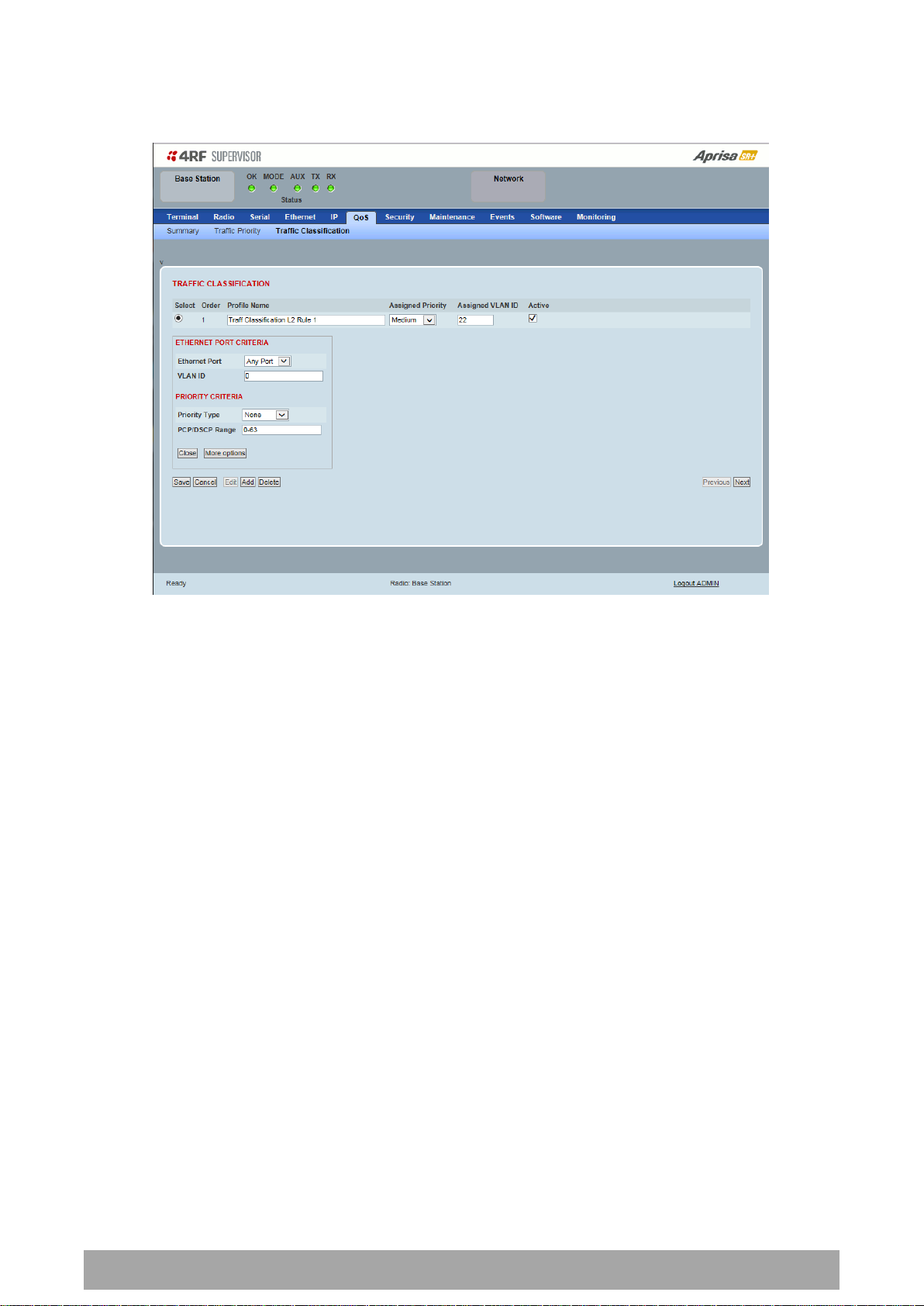
Bridge Mode Traffic Classification Settings
TRAFFIC CLASSIFICATION
VLAN bridge mode traffic classification settings provide mapping / assigning of profiles (set by rules to
match a specific traffic type) to a VLAN ID and VLAN CoS / priority. The profile which is used to match to
a specific traffic type will be identified in the radio network by its associated VLAN ID and VLAN CoS /
priority to provide the appropriate QoS treatment. CoS / Priority can be set to very high, high, medium,
low priority.
Profile name
A free form field to enter the profile name with a maximum of 32 chars.
Assigned Priority
Traffic packets that match the applied profile rules will be assigned to the selected ‘assigned priority’
setting of Very High, High, Medium and Low. This field cannot be set to Don’t Care.
This applies profile rule mapping to the VLAN CoS / Priority with the appropriate internal radio assigned
priority setting of Very High, High, Medium and Low.

Managing the Radio | 169
Aprisa SR+ User Manual 1.6.0 PO
Assigned VLAN ID
Traffic packets that match the applied profile rules will be assigned to the selected ‘assigned VLAN ID’
setting of VLAN ID in the range of 0 to 4095.
A VLAN ID of an ingress packet matching the classification rule (see ‘VLAN ID’ rule in next page) shall be
changed to the ‘assigned VLAN ID’ setting, if below conditions are met:
1. The VLAN ID of Ingress packet is same as PVID of the ingress port.
2. Packet is received untagged at the port
If the VLAN ID of the tagged ingress packet is not the same as the PVID of the ingress port, then it shall
not be changed and the ‘assigned VLAN ID’ setting is ignored i.e. ingress VLANs will pass-through
unchanged.
If ‘assigned VLAN ID’ value is set in the ‘port VLAN membership’ under Ethernet > VLAN (port x tab), then
this VLAN will be available for ingress and egress on the Ethernet and RF ports, otherwise this VLAN will
only be available in one direction on the egress RF port.
For example, if the base station Ethernet port 1 ‘assigned VLAN ID’ = 100 (VLAN -100) and it is also defined
in the ‘port VLAN membership’ under Ethernet > VLAN (port 1 tab) and the remote sends a packet to the
base with a VLAN of 100, this packet will be egress out to Ethernet port 1 (tagged or untagged based on
the ‘egress action’ definition). If the VLAN-100 wasn’t set in the ‘port VLAN membership’, then the base
station will drop a packet from the remote.
This setting parameter can be ‘Don’t Care’ (Assigned VLAN ID = 0) which means that the VLAN ID of ingress
frame will never be modified.
Active
Activates or deactivates the profile rule.
Controls
The Save button saves all profiles to the radio.
The Cancel button removes all changes since the last save or first view of the page if there has not been
any saves. This button will un-select all the Select radio buttons.
The Edit button will show the next screen for the selected profile where the profile can be configured.
This button will be disabled unless a profile is selected.
The Add button adds a new profile,
If no profile was selected then the new profile is added to the end of the list,
If a profile is selected the new profile is added after that profile.
The Delete button will delete the selected profile. The button will be disabled unless a profile has been
selected.
The Delete All button will delete all the profiles. A pop-up will ask if the action is correct. If the answer is
yes, then all profiles are deleted in SuperVisor. The Save button must be pressed to delete all the profiles
in the radio.
The Move up button will move the selected profile up one in the order of profiles
The Move Down button will move the selected profile down one in the order of profiles
The Previous button displays the previous page in the list of profiles. A pop up will be displayed if any
profile has been modified and not saved, preventing the previous page being displayed.
The Next button will display the next page in the list of profiles.
170 | Managing the Radio
Aprisa SR+ User Manual 1.6.0 PO
To edit a traffic classification, select the profile and click on the Edit button
ETHERNET PORT CRITERIA
Ethernet Port
Set the layer 1 Ethernet port number or all Ethernet ports in the selected profile classification rule.
VLAN ID
Sets the layer 2 packet Ethernet header VLAD ID field in the selected profile classification rule. Valid
values are between 0 and 4095. This VLAN ID should be enabled in the system for using this parameter
during classification.
Enable this VLAN in the network by setting the same VLAN ID value in PVID (port VLAN ID) and in the PORT
VLAN MEMBERSHIP under ‘VLAN PORT SETTINGS – Port 1’ on page 144. If the VLAN ID is set to zero, all
VLAN IDs will meet the criteria.

Managing the Radio | 171
Aprisa SR+ User Manual 1.6.0 PO
Priority Type
Description
None
Do not use any layer 2 / 3 Ethernet or IP header
priority fields in the selected profile classification
rules.
PCP
Use the layer 2 Ethernet header priority field of
PCP (Priority Code Point) VLAN priority bits (per
IEEE 802.1p/q) in the selected profile
classification rules.
DSCP
Use the layer 3 IP header TOS field used as DSCP
(Differentiated Services Code Point per RFC 2474
and RFC 2475) priority bit in the selected profile
classification rules.
PCP Value
(Decimal)
PCP Priority
Priority Level
7
Priority [7]
Highest
6
Priority [6]
5 Priority [5]
4 Priority [4]
3
Priority [3]
2 Priority [2]
1
Priority [1]
0 Priority [0]
Lowest
PRIORITY CRITERIA
Priority Type
Set the layer 2 Ethernet or layer 3 IP packet header priority type fields in the selected profile
classification rules.
PCP / DSCP Range
As per the ‘priority type’ selection, this parameter sets the PCP priority value/s or DSCP priority value/s
fields in the selected profile classification rule. The value can be set to a single priority or a single range
(no multiple ranges are allowed), for example, the PCP selected priority value can be 7 or a range of
priority values like 4-7.
The following table shows the layer 2 packet VLAN tag header PCP priority field values

172 | Managing the Radio
Aprisa SR+ User Manual 1.6.0 PO
DSCP Value
(Decimal)
DSCP Priority
46
EF (Expedited Forwarding)
10
AF11 (Assured Forwarding)
12
AF12
14
AF13
18
AF21
20
AF22
22
AF23
26
AF31
28
AF32
30
AF33
34
AF41
36
AF42
38
AF43
0
CS0/Best Effort (BE)
8
CS1 (Class Selector )
16
CS2
24
CS3
32
CS4
40
CS5
48
CS6
56
CS7
The following table shows the layer 3 packet IP header DSCP priority field values
Managing the Radio | 173
Aprisa SR+ User Manual 1.6.0 PO
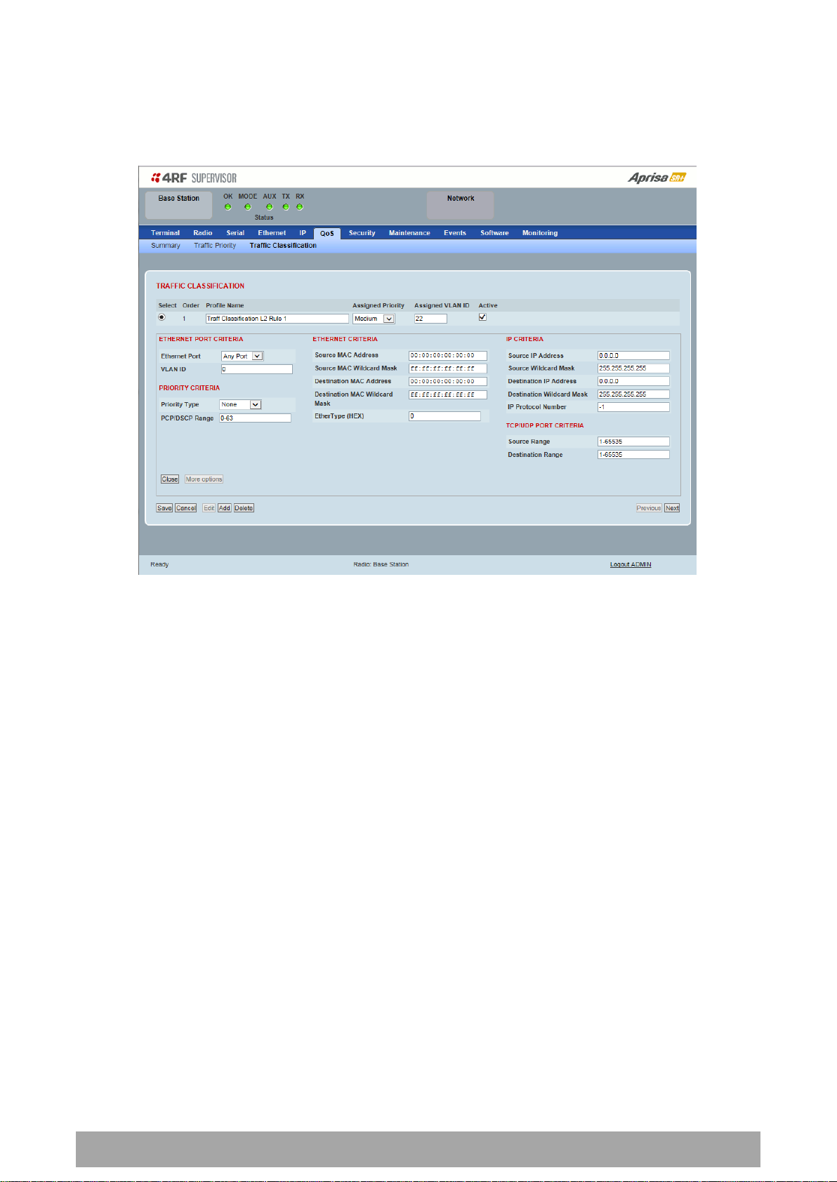
Click on More Options if more Layer 2/3/4 (Ethernet / IP / TCP or UDP) packet header fields are required
for the selected profile classification rule. This page describes all the possible fields that can be used for
the classification rules in bridge mode.
ETHERNET CRITERIA
Source MAC Address
This parameter sets the Layer 2 Ethernet packet header Source MAC Address field in the selected profile
classification rule in the format of ‘hh:hh:hh:hh:hh:hh’.
Source MAC Wildcard Mask
This parameter sets the wildcard mask of the ‘Source MAC Address’. If the Source MAC Address is set to
‘FF:FF:FF:FF:FF:FF’, all source MAC addresses will meet the criteria.
Destination MAC Address
This parameter sets the Layer 2 Ethernet packet header Destination MAC Address field in the selected
profile classification rule in the format of ‘hh:hh:hh:hh:hh:hh’.
Destination MAC Wildcard Mask
This parameter sets the wildcard mask of the ‘Destination MAC Address’. If the Destination MAC Address is
set to ‘FF:FF:FF:FF:FF:FF’, all destination MAC addresses will meet the criteria.

174 | Managing the Radio
Aprisa SR+ User Manual 1.6.0 PO
Protocol
EtherType Value
(Hexadecimal)
IPv4
0800
ARP
0806
IPv6
86DD
VLAN
8100
EtherType (Hex)
This parameter sets the Layer 2 Ethernet packet header EtherType field in the selected profile
classification rule. EtherType is a 16 bit (two octets) field in an Ethernet frame. It is used to indicate
which protocol is encapsulated in the payload of an Ethernet Frame.
EtherType Examples:
IP CRITERIA
Source IP Address
This parameter sets the Layer 3 IP packet header Source IP Address field in the selected profile
classification rule. This parameter is written in the standard IPv4 format of ‘xxx.xxx.xxx.xxx’.
Source IP Wildcard Mask
This parameter sets the wildcard mask applied to the ‘Source IP Address’. This parameter is written in th e
standard IPv4 format of ‘xxx.xxx.xxx.xxx’.
0 means that it must be a match. If the wildcard mask is set to 0.0.0.0, the complete Source IP Address
will be evaluated for the classification rule.
If the wildcard mask is set to 0.0.255.255, the first 2 octets of the Source IP Address will be evaluated for
the classification rule.
If the wildcard mask is set to 255.255.255.255, none of the Source IP Address will be evaluated for the
classification rule.
Note: The wildcard mask operation is the inverse of subnet mask operation
Destination IP Address
This parameter sets the Layer 3 IP packet header Destination IP Address field in the selected profile
classification rule. This parameter is written in the standard IPv4 format of ‘xxx.xxx.xxx.xxx’.
Destination IP Wildcard Mask
This parameter sets the wildcard mask applied to the ‘Destination IP Address’. This parameter is written
in the standard IPv4 format of ‘xxx.xxx.xxx.xxx’.
0 means that it must be a match. If the wildcard mask is set to 0.0.0.0, the complete Destination IP
Address will be evaluated for the classification rule.
If the wildcard mask is set to 0.0.255.255, the first 2 octets of the Destination IP Address will be evaluated
for the classification rule.
If the wildcard mask is set to 255.255.255.255, none of the Destination IP Address will be evaluated for
the classification rule.
Note: The wildcard mask operation is the inverse of subnet mask operation

Managing the Radio | 175
Aprisa SR+ User Manual 1.6.0 PO
Protocol
Protocol value
(decimal)
ICMP
1
TCP
6
UDP
17
Protocol
TCP / UDP Port #
(decimal)
Modbus
502
IEC 60870-5-104
2,404
DNP 3
20,000
SNMP
161
SNMP TRAP
162
IP Protocol Number
This parameter sets the Layer 3 IP packet header ‘Protocol’ field in the selected profile classification rule.
This field defines the protocol used in the data portion of the IP datagram.
Protocol number Examples:
TCP / UDP PORT CRITERIA
Source Range
This parameter sets the Layer 4 TCP / UDP packet header Source Port or Source Port range field in the
selected profile classification rule. To specify a range, insert a dash between the ports e.g. 1000-2000. If
the source port range is set to 1-65535, traffic from any source port will meet the criteria.
Destination Range
This parameter sets the Layer 4 TCP / UDP packet header Destination Port or Destination Port range field
in the selected profile classification rules. To specify a range, insert a dash between the ports e.g. 1000-
2000. If the source port range is set to 1-65535, traffic from any source port will meet the criteria.
Examples for TCP / UDP Port Numbers:

176 | Managing the Radio
Aprisa SR+ User Manual 1.6.0 PO
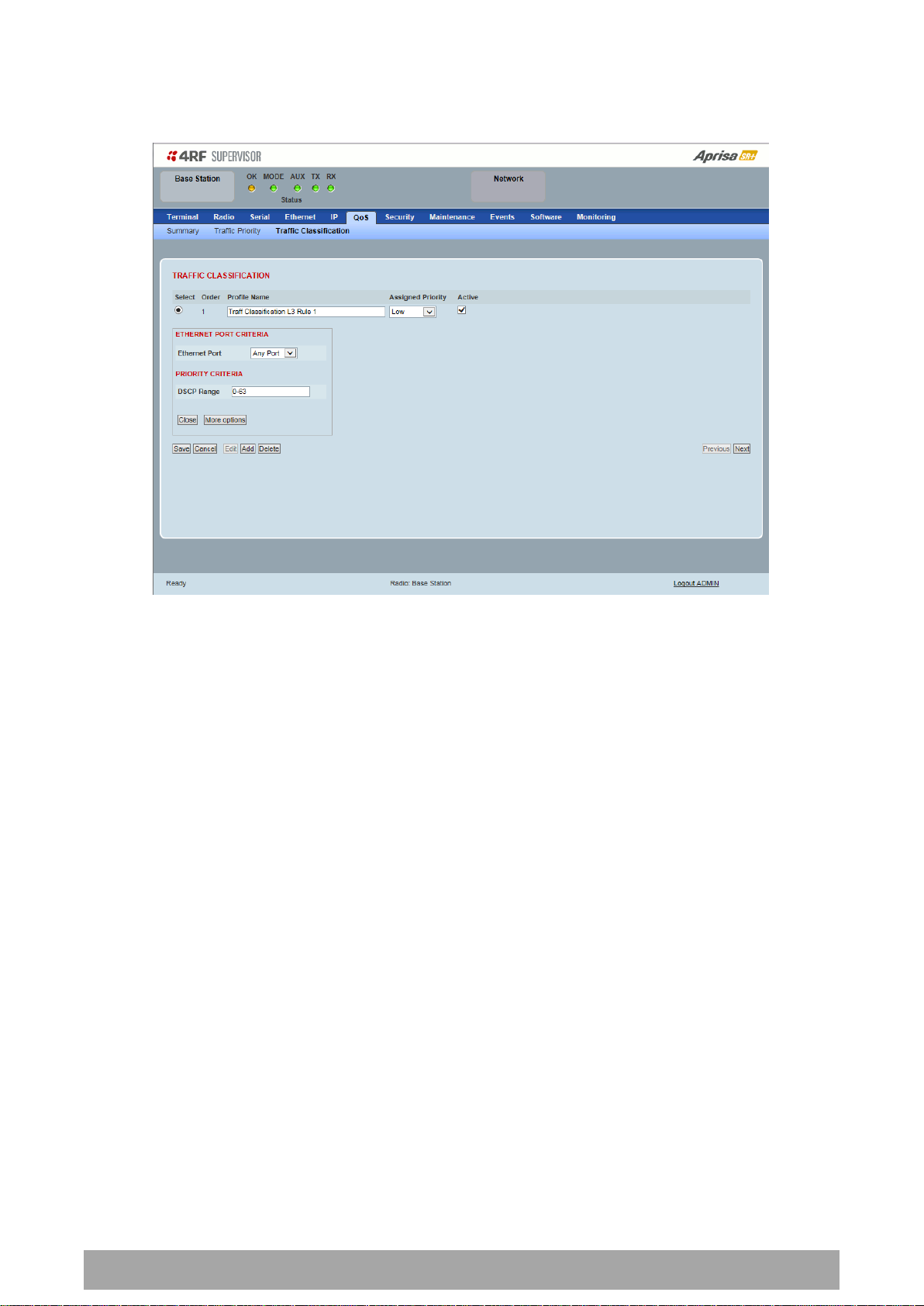
Router Mode Traffic Classification Settings
TRAFFIC CLASSIFICATION
Router Mode traffic classification settings provide mapping / assigning of profiles (set by rules to match a
specific traffic type) to a CoS / priority. The profile which is used to match to a specific traffic type will
be identified in the radio network by its associated CoS / priority to provide the appropriate QoS
treatment. CoS / Priority can be set to very high, high, medium, low priority.
Profile name
A free form field to enter the profile name with a maximum of 32 chars.
Assigned Priority
Traffic packets that match the applied profile rules will be assigned to the selected ‘assigned priority’
setting of Very High, High, Medium and Low. This field cannot be set to Don’t Care.
Active
Activated or deactivate the profile rule.

Managing the Radio | 177
Aprisa SR+ User Manual 1.6.0 PO
Controls
The Save button saves all profiles to the radio.
The Cancel button removes all changes since the last save or first view of the page if there has not been
any saves. This button will un-select all the Select radio buttons.
The Edit button will show the next screen for the selected profile where the profile can be configured.
This button will be disabled unless a profile is selected.
The Add button adds a new profile,
If no profile was selected then the new profile is added to the end of the list,
If a profile is selected the new profile is added after that profile.
The Delete button will delete the selected profile. The button will be disabled unless a profile has been
selected.
The Delete All button will delete all the profiles. A pop-up will ask if the action is correct. If the answer is
yes, then all profiles are deleted in SuperVisor. The Save button must be pressed to delete all the profiles
in the radio.
The Move up button will move the selected profile up one in the order of profiles
The Move Down button will move the selected profile down one in the order of profiles
The Previous button displays the previous page in the list of profiles. A pop up will be displayed if any
profile has been modified and not saved, preventing the previous page being displayed.
The Next button will display the next page in the list of profiles.
178 | Managing the Radio
Aprisa SR+ User Manual 1.6.0 PO
To edit a traffic classification, select the profile and click on the Edit button
ETHERNET PORT CRITERIA
Ethernet Port
Set the layer 1 Ethernet port number or all Ethernet ports in the selected profile classification rules.
PRIORITY CRITERIA
DSCP Range
Sets the DSCP priority value/s field in the selected profile classification rule. The value can be set to a
single priority or a single range (no multiple range are allowed), for example, priority value can be 46 (EF)
or a range of priority values like 10-14.

Managing the Radio | 179
Aprisa SR+ User Manual 1.6.0 PO
DSCP Value
(Decimal)
DSCP Priority
46
EF (Expedited Forwarding)
10
AF11 (Assured Forwarding)
12
AF12
14
AF13
18
AF21
20
AF22
22
AF23
26
AF31
28
AF32
30
AF33
34
AF41
36
AF42
38
AF43
0
CS0/Best Effort (BE)
8
CS1 (Class Selector )
16
CS2
24
CS3
32
CS4
40
CS5
48
CS6
56
CS7
The following table shows the layer 3 packet IP header DSCP priority field values

180 | Managing the Radio
Aprisa SR+ User Manual 1.6.0 PO
Click on More Options if more Layer 3/4 packet header fields are required for the selected profile
classification rule. This page describes all the possible fields that can be used for the classification rules in
router mode.
IP CRITERIA
Source IP Address
This parameter sets the Layer 3 packet IP header Source IP Address field in the selected profile
classification rules. This parameter is written in the standard IPv4 format of ‘xxx.xxx.xxx.xxx’.
Source IP Wildcard Mask
This parameter sets the wildcard mask applied to the ‘Source IP Address’. This parameter is written in the
standard IPv4 format of ‘xxx.xxx.xxx.xxx’.
0 means that it must be a match. If the wildcard mask is set to 0.0.0.0, the complete Source IP Address
will be evaluated for the classification rules.
If the wildcard mask is set to 0.0.255.255, the first 2 octets of the Source IP Address will be evaluated for
the classification rules.
If the wildcard mask is set to 255.255.255.255, none of the Source IP Address will be evaluated for the
classification rules.
Note: The wildcard mask operation is the inverse of subnet mask operation
Destination IP Address
This parameter sets the Layer 3 packet IP header Destination IP Address field in the selected profile
classification rules. This parameter is written in the standard IPv4 format of ‘xxx.xxx.xxx.xxx’.

Managing the Radio | 181
Aprisa SR+ User Manual 1.6.0 PO
Protocol
Protocol value
(decimal)
ICMP
1
TCP
6
UDP
17
Protocol
TCP / UDP Port #
(decimal)
Modbus
502
IEC 60870-5-104
2,404
DNP 3
20,000
SNMP
161
SNMP TRAP
162
Destination IP Wildcard Mask
This parameter sets the wildcard mask applied to the ‘Destination IP Address’. This parameter is written
in the standard IPv4 format of ‘xxx.xxx.xxx.xxx’.
0 means that it must be a match. If the wildcard mask is set to 0.0.0.0, the complete Destination IP
Address will be evaluated for the classification rules.
If the wildcard mask is set to 0.0.255.255, the first 2 octets of the Destination IP Address will be evaluated
for the classification rules.
If the wildcard mask is set to 255.255.255.255, none of the Destination IP Address will be evaluated for
the classification rules.
Note: The wildcard mask operation is the inverse of subnet mask operation
Protocol Number
This parameter sets the Layer 3 IP packet header ‘Protocol’ field in the selected profile classification rule.
This field defines the protocol used in the data portion of the IP datagram.
Protocol number Examples:
TCP / UDP Port Criteria
Source Range
This parameter sets the Layer 4 TCP / UDP packet header Source Port or Source Port range field in the
selected profile classification rule. To specify a range, insert a dash between the ports e.g. 1000-2000. If
the source port range is set to 1-65535, traffic from any source port will meet the criteria.
Destination Range
This parameter sets the Layer 4 TCP / UDP packet header Destination Port or Destination Port range field
in the selected profile classification rule. To specify a range, insert a dash between the ports e.g. 1000-
2000. If the source port range is set to 1-65535, traffic from any source port will meet the criteria.
Examples for TCP / UDP Port Numbers:

182 | Managing the Radio
Aprisa SR+ User Manual 1.6.0 PO
Security
Security > Summary
This page displays the current settings for the Security parameters.
See ‘Security > Setup’ and ‘Security > Manager’ for configuration options.

Managing the Radio | 183
Aprisa SR+ User Manual 1.6.0 PO
Security Scheme
Disabled (No encryption and no Message Authentication Code)
AES Encryption + CCM Authentication 128 bit
AES Encryption + CCM Authentication 64 bit
AES Encryption + CCM Authentication 32 bit
AES Encryption only
CCM Authentication 128 bit
CCM Authentication 64 bit
CCM Authentication 32 bit
Security > Setup
PAYLOAD SECURITY PROFILE SETTINGS
Security Profile Name
This parameter enables the user to predefine a security profile with a specified name.
Security Scheme
This parameter sets the security scheme to one of the values in the following table:
The default setting is Disabled.

184 | Managing the Radio
Aprisa SR+ User Manual 1.6.0 PO
Option
Function
Pass Phrase
Use the Pass Phrase password format for standard security.
Raw Hexadecimal
Use the Raw Hexadecimal key format for better security. It
must comply with the specified encryption key size e.g. if
Encryption Type to AES128, the encryption key must be 16
bytes (32 chars)
Payload Encryption Key Type
This parameter sets the Payload Encryption Key Type:
The default setting is Pass Phrase.
Payload Encryption Key Size
This parameter sets the Encryption Type to AES128, AES192 or AES256. The default setting is AES128.
The higher the encryption size the better the security.
Payload Encryption Key
This parameter sets the Payload Encryption password. This key is used to encrypt the payload.
Pass Phrase
Good password policy:
contains at least eight characters, and
contains at least one upper case letter, and
contains at least one lower case letter, and
contains at least one digit or another character such as @+... , and
is not a term in a familiar language or jargon, and
is not identical to or derived from the accompanying account name, from personal characteristics
or from information from one’s family/social circle, and
is easy to remember, for instance by means of a key sentence
Raw Hexadecimal
The Raw Hexadecimal key must comply with the specified encryption key size e.g. if Encryption Type to
AES128, the encryption key must be 16 bytes (32 chars).

Managing the Radio | 185
Aprisa SR+ User Manual 1.6.0 PO
Option
Function
Pass Phrase
Use the Pass Phrase password format for standard security.
Raw Hexadecimal
Use the Raw Hexadecimal key format for better security. It
must comply with the specified encryption key size
e.g. if Encryption Type to AES128, the encryption key must
be 16 bytes (32 chars)
Option
Function
USB Storage Not Detected
A USB flash drive is not plugged into the radio host port.
USB Storage Detected
A USB flash drive is plugged into the radio host port.
KEY ENCRYPTION KEY SETTINGS
The Key Encryption Key provides the ability to encrypt the Payload Encryption Key so it can be safely
transmitted over the radio link to remote radios.
The Key Encryption Key Type, Key Encryption Key Size and Key Encryption Key must be the same on all
radios in the network.
Key Encryption Key Type
This parameter sets the Payload Encryption Key Type:
The default setting is Pass Phrase.
Key Encryption Key Size
This parameter sets the Encryption Type to AES128, AES192 or AES256. The default setting is AES128.
The higher the encryption type the better the security.
Key Encryption Key
This parameter sets the Key Encryption Key. This is used to encrypt the payload encryption key.
USB Transaction Status
This parameter shows if a USB flash drive is plugged into the radio host port .
Note: Some brands of USB flash drives may not work with 4RF radios.
Controls
The ‘Save’ button saves the Key Encryption Key settings to the radio. If the Security Level is set to Strong
(see ‘Security Level’ on page 191), this button will be grayed out.
The ‘Load From USB’ button loads the Key Encryption Key settings from the USB flash drive. If a USB flash
drive is not detected, this button will be grayed out
The ‘Copy To USB’ button copies the Key Encryption Key settings to a file called ‘asrkek.txt’ on the USB
flash drive. This settings file can be used to load into other radios. If a USB flash drive is not detected or
the Security Level is set to Strong (see ‘Security Level’ on page 191), this button will not be shown.

186 | Managing the Radio
Aprisa SR+ User Manual 1.6.0 PO
Key Encryption Key Summary
The security of over-the-air-rekeying depends on a truly random Key Encryption Key. This is why the use
of a Raw Hexadecimal key is recommended as a plain text phrase based on known spelling and grammar
constructs is not very random. The default Key Encryption Key is provided only to allow testing of the
security mechanism and is not intended for operational use. Using the default Key Encryption Key
undermines the security of the AES payload encryption because an attacker using the default Key
Encryption Key would immediately recover the AES payload key after the first over-the-air-rekeying event.
When the Security Level is set to Strong, various protections are applied to the Key Encryption Key setting
to prevent tampering. In addition, the Key Encryption Key Type, Key Encryption Key Size, and the Key
Encryption Key itself are all loaded from a customer prepared USB key. This is a one way operation to
prevent key recovery from radios. While the ability to save a Key Encryption Key to USB exists in Standard
Security Level, the Strong Security Level Key Encryption Key is not compromised because the Strong Key
Encryption Key is not the same as the Standard Security Level Key Encryption Key.

Managing the Radio | 187
Aprisa SR+ User Manual 1.6.0 PO
Option
Function
Disabled
All SNMP functions are disabled.
All Versions
Allows all SNMP protocol versions.
SNMPv3 Only
Only SNMPv3 transactions will be accepted.
SNMPv3 With
Authentication Only
Only SNMPv3 transactions authenticated using HMAC-MD5 or
HMAC-SHA will be accepted (as per table below).
SNMPv3 With Encryption
Only
Only SNMPv3 transactions with an encrypted type of DES or
AES will be accepted (as per table below).
User Name
Encryption
Type
Authentication
Type
Context
Name
Authentication
Passphrase
Encryption
Passphrase
noAuthUser
- - noAuth
noAuthUser
noAuthUser
desUserMD5
DES
MD5
priv
desUserMD5
desUserMD5
desUserSHA
DES
SHA
priv
desUserSHA
desUserSHA
authUserMD5
-
MD5
auth
authUserMD5
authUserMD5
authUserSHA
-
SHA
auth
authUserSHA
authUserSHA
privUserMD5
AES
MD5
priv
privUserMD5
privUserMD5
privUserSHA
AES
SHA
priv
privUserSHA
privUserSHA
PROTOCOL SECURITY SETTINGS
Telnet option
This parameter option determines if you can manage the radio via a Telnet session. The default setting is
disabled.
ICMP option (Internet Control Message Protocol)
This parameter option determines whether the radio will respond to a ping. The default setting is
disabled.
HTTPS option
This parameter option determines if you can manage the radio via a HTTPS session (via a Browser). The
default setting is enabled.
SNMP Proxy Support
This parameter option enables an SNMP proxy server in the base station. This proxy server reduces the
radio link traffic during SNMP communication to remote / repeater stations. This option applies to the
base station only. The default setting is disabled.
This option can also be used if the radio has Serial Only interfaces.
SNMP Protocol
This parameter sets the SNMP Protocol:
The default setting is All Versions.
The default SNMPv3 with Authentication User Details provided are:

188 | Managing the Radio
Aprisa SR+ User Manual 1.6.0 PO
SNMPv3 Authentication Passphrase
The SNMPv3 Authentication Passphrase can be changed via the SNMPv3 secure management protocol
interface (not via SuperVisor).
When viewing / managing the details of the users via SNMPv3, the standard SNMP-USER-BASED-SM-MIB
interface is used. This interface can be used to change the SNMPv3 Authentication Passphrase of the users.
The SNMPv3 Authentication Passphrase of a user required to be changed cannot be changed by the same
user i.e. a different user must be used for the transactions.
Generate New Keys from SNMPv3 USM User Passphrases
Net-SNMP is a suite of open source software for using and deploying the SNMP protocol. Similar
functionality is built into many commercial SNMP managers.
This next step of loading the Aprisa SR+ radios with keys generated from USM user passphrases requires
the SNMPv3 USM Management utility provided as part of NET-SNMP.
The utility is called ‘snmpusm’. It provides a range of commands including the management of changing
passwords for SNMPv3 users. In order to use this utility, the user will need to install NET-SNMP on a Linux
(or Windows®) or machine. The examples below are from the Linux environment. This tool automatically
obtains the engine ID from the target radio before generating the keys and loading them into the target.
To change a user authentication passphrase:
The following are examples of:
Changing the privUserSHA user encryption key / password from privUserSHA to privUserSHANew:
c:\usr\bin>snmpusm -v 3 -u privUserSHA -n priv -l authPriv -a SHA -A privUserSHA -x AES -X
privUserSHA -Cx 172.17.70.17 passwd privUserSHA privUserSHANew
Changing the privUserSHA user authentication key / password from privUserSHA to privUserSHANew:
c:\usr\bin>snmpusm -v 3 -u privUserSHA -n priv -l authPriv -a SHA -A privUserSHA -x AES -X
privUserSHANew -Ca 172.17.70.17 passwd privUserSHA privUserSHANew
Changing the desUserSHA user encryption key / password from desUserSHA to desUserSHANew:
c:\usr\bin>snmpusm -v 3 -u desUserSHA -n priv -l authPriv -a SHA -A desUserSHA -x DES -X desUserSHA
-Cx 172.17.70.17 passwd desUserSHA desUserSHANew
Changing the desUserSHA user authentication key / password from desUserSHA to desUserSHANew:
c:\usr\bin>snmpusm -v 3 -u desUserSHA -n priv -l authPriv -a SHA -A desUserSHA -x DES -X
desUserSHANew -Ca 172.17.70.17 passwd desUserSHA desUserSHANew
Changing the privUserMD5 user encryption key / password from privUserMD5 to privUserMD5New:
c:\usr\bin>snmpusm -v 3 -u privUserMD5 -n priv -l authPriv -a MD5 -A privUserMD5 -x AES -X
privUserMD5 -Cx 172.17.70.17 passwd privUserMD5 privUserMD5New
Changing the privUserMD5 user authentication key / password from privUserMD5 to privUserMD5New:
c:\usr\bin>snmpusm -v 3 -u privUserMD5 -n priv -l authPriv -a MD5 -A privUserMD5 -x AES -X
privUserMD5New -Ca 172.17.70.17 passwd privUserMD5 privUserMD5New

Managing the Radio | 189
Aprisa SR+ User Manual 1.6.0 PO
Changing the desUserMD5 user encryption key / password from desUserMD5 to desUserMD5New:
c:\usr\bin>snmpusm -v 3 -u desUserMD5 -n priv -l authPriv -a MD5 -A desUserMD5 -x DES -X
desUserMD5 -Cx 172.17.70.17 passwd desUserMD5 desUserMD5New
Changing the desUserMD5 user authentication key / password from desUserMD5 to desUserMD5New:
c:\usr\bin>snmpusm -v 3 -u desUserMD5 -n priv -l authPriv -a MD5 -A desUserMD5 -x DES -X
desUserMD5New -Ca 172.17.70.17 passwd desUserMD5 desUserMD5New
Changing the authUserSHA user authentication key / password from authUserSHA to authUserSHANew:
c:\usr\bin>snmpusm -v 3 -u authUserSHA -n auth -l authNoPriv -a SHA -A authUserSHA -Ca
172.17.70.17 passwd authUserSHA authUserSHANew
Changing the authUserMD5 user authentication key / password from authUserMD5 to authUserMD5New:
c:\usr\bin>snmpusm -v 3 -u authUserMD5 -n auth -l authNoPriv -a MD5 -A authUserMD5 -Ca
172.17.70.17 passwd authUserMD5 authUserMD5New
Notes
-Cx option is to change the Encryption key/password
-Ca option is to change the Authentication key/password
Other information on this utility can be obtained from the utility command help itself or online
Summary
It is necessary to record the new passphrases loaded into the Aprisa SR+ radios and then load the
passphrases into the SNMP manager. There is a separate passphrase for the two supported forms of
authentication (MD5 and SHA1) only as well as the two forms of authentication used in combination the
two forms of encryption (DES and AES). It is vital to change all passphrases even if the depreciated
mechanism are not used (MD5 and DES) otherwise an attacker could still use the default passphrases.

190 | Managing the Radio
Aprisa SR+ User Manual 1.6.0 PO
Reset Unknown Passphrases with the Command Line Interface
As it is not possible for users to read previously set passphrases, a CLI command is available from Aprisa
SR+ software release 1.4.0 to ‘reset’ the SNMPv3 USM users back to defaults.
Note: USM users are not related to CLI and SuperVisor users. This command will only be accessible to the
CLI ‘admin’ user logins.
To reset unknown passphrases:
1. Telnet into each radio in the network and via the CLI reset the passphrases
2. Login to the radio with:
Login: admin
Password: *********
3. Set all SNMP3 users to default values with the ‘snmpusm reset’ command (see ‘SNMP3 users to default
values’ below for the list of default values).
4. Reboot the radio with the ‘reboot’ command.

Managing the Radio | 191
Aprisa SR+ User Manual 1.6.0 PO
Option
Payload
Encryption
HTTPS
SNMPv3
USB KEK Only
Standard
Strong
SECURITY LEVEL SETTINGS
Security Level
This parameter sets the Security Level active security features. The default setting is Standard.
If the Security Level is reduced, there will be a pop up message warning that Key Encryption Key will be
reset to the default value.
If the Security Level is increased, there will be a pop up message reminding user to enter a new Key
Encryption Key.
If the Security Level is set to Strong, the ‘Save’ button will be grayed out and the ‘Copy To USB’ button
will not be shown.
SNMPv3 Context Addressing
SNMPv3 is not user configurable and user can use this option with any NMS. The radio SNMP management
interface supports SNMPv3/2 context addressing. The SNMv3 context addressing allows the user to use
secure SNMPv3 management while improving NMS performance.
A NMS (Network Management System) can access any remote radio directly by using its IP address or via
the base / master station SNMPv3 context addressing. The SNMPv3 context addressing can compress the
SNMPv3 management traffic OTA (Over The Air) to the remote station by up to 90% relative to direct OTA
SNMPv3 access to remote station, avoiding the radio narrow bandwidth traffic loading.

192 | Managing the Radio
Aprisa SR+ User Manual 1.6.0 PO
Security > Users
Note: You must login with ‘admin’ privileges to add, disable, delete a user or change a password.
USER DETAILS
Shows a list of the current users setup in the radio.
ADD NEW USER
To add a new user:
1. Enter the Username.
A username can be up to 32 characters but cannot contain back slashes, forward slashes, spaces, tabs,
single or double quotes. Usernames are case sensitive.
2. Enter the Password.
A password can be 8 to 32 printable characters but cannot contain a tab. Passwords are case sensitive.
Good password policy:
contains at least eight characters, and
contains at least one upper case letter, and
contains at least one lower case letter, and
contains at least one digit or another character such as !@#$%^&(){}[]<>... , and
is not a term in a familiar language or jargon, and
is not identical to or derived from the accompanying account name, from personal characteristics
or from information from one’s family/social circle, and
is easy to remember, for instance by means of a key sentence
3. Select the User Privileges

Managing the Radio | 193
Aprisa SR+ User Manual 1.6.0 PO
User
Privilege
Default
Username
Default
Password
User Privileges
View
Users in this group can only view the summary
pages.
Technician
Users in this group can view and edit parameters
except Security > Users and Security > Setup.
Engineer
Users in this group can view and edit parameters
except Security > Users.
Admin
admin
admin
Users in this group can view and edit all
parameters.
There are four pre-defined User Privilege settings to allocate access rights to users. These user privileges
have associated default usernames and passwords of the same name.
The default login is ‘admin’.
This login has full access to all radio parameters including the ability to add and change users. There can
only be a maximum of two usernames with admin privileges and the last username with admin privileges
cannot be deleted.
See ‘SuperVisor Menu Access’ on page 80 for the list of SuperVisor menu items versus user privileges.
4. Click ‘Add’
To delete a user:
1. Select Terminal Settings > Security > Users
2. Click on the Select button for the user you wish to delete.
3. Click ‘Delete
To change a Password:
1. Select Terminal Settings > Security > Users
2. Click on the Select button for the user you wish to change the Password.
3. Enter the Password.
A password can be 8 to 32 characters but cannot contain back slashes, forward slashes, spaces, tabs,
single or double quotes.

194 | Managing the Radio
Aprisa SR+ User Manual 1.6.0 PO
Security > SNMP
In addition to web-based management (SuperVisor), the network can also be managed using the Simple
Network Management Protocol (SNMP) using any version of SNMP v1/2/3. MIB files are supplied, and these
can be used by a dedicated SNMP Manager, such as Castle Rock’s SNMPc, to access most of the radio’s
configurable parameters.
For communication between the SNMP manager and the radio, Access Controls and Community strings
must be set up as described in the following sections.
A SNMP Community String is used to protect against unauthorized access (similar to a password). The
SNMP agent (radio or SNMP manager) will check the community string before performing the task
requested in the SNMP message.
ACCESS CONTROL SETUP
A SNMP Access Control is the IP address of the radio used by an SNMP manager or any other SNMP device
to access the radio. The Aprisa SR+ allows access to the radio from any IP address.
Read Only
The default Read Only community string is public.
Read Write
The default ReadWrite community string is private.

Managing the Radio | 195
Aprisa SR+ User Manual 1.6.0 PO
SNMP Manager Setup
The SNMP manager community strings must be setup to access the base station and remote / repeater
stations.
To access the base station, a community string must be setup on the SNMP manager the same as the
community string setup on the radio (see ‘Security > SNMP’ on page 194).
SNMP access to remote / repeater stations can be achieved by using the radio’s IP address and the normal
community string or by proxy in the base station.
SNMP Access via Base Station Proxy
To access the remote / repeater stations via the base station proxy, the community strings must be setup
on the SNMP manager in the format:
ccccccccc:bbbbbb
Where:
ccccccccc is the community string of the base station
and
bbbbbb is the last 3 bytes of the remote station MAC address (see ‘Network Status > Network Table’
on page 271).
The SNMP Proxy Support must be enabled for this method of SNMP access to operate (see ‘SNMP Proxy
Support’ on page 187).

196 | Managing the Radio
Aprisa SR+ User Manual 1.6.0 PO
Security > RADIUS
This page displays the current settings for the Security RADIUS.
RADIUS - Remote Authentication Dial In User Service
RADIUS is a client / server system that secures the radio link against unauthorized access. It is based on
open standard RFCs: RFC 2865/6, 5607, 5080 and 2869. It is used for remote user Authorization,
Authentication and Accounting.
When a user logs into a radio with RADIUS enabled, the user’s credentials are sent to the RADIUS server
for authentication of the user.
Transactions between the RADIUS client and RADIUS server are authenticated through the use of a shared
secret, which is never sent over the network.
For a RADIUS server to respond to the radio, it must configured with and respond to the following
Management-Privilege-level attributes:
Admin Level = 4
Technician Level = 2
Viewer Level = 1
A RADIUS server can act as a proxy client to other RADIUS servers or other kinds of authentication servers.

Managing the Radio | 197
Aprisa SR+ User Manual 1.6.0 PO
Option
Function
Local Authentication
No radius Authentication – allows any local user privilege
Radius Authentication
Only radius Authentication – no local user privilege
Radius Authentication
and Local admin
Uses radius Authentication if it is available.
If radius Authentication is not available, uses local Admin login
Radius Then Local
Authentication
If the user is not authenticated in the radius server, it allows any
local user privilege.
Local Then Radius
Authentication
If the user is not allowed in the local user privilege, radius
authentication is used.
RADIUS AUTHENTICATION SETTINGS
Authentication Mode
This parameter sets the Authentication Mode.
Primary Server
This parameter sets which radius server is used as the primary server for authentication. Select one of the
possible authentication servers setup in Radius Server Settings.
Secondary Server
This parameter sets which radius server is used as the secondary server for authentication. Select one of
the possible authentication servers setup in Radius Server Settings.
RADIUS ACCOUNTING SETTINGS
Primary Server
This parameter sets which radius server is used as the primary server for accounting (log of user activity).
Select one of the possible accounting servers setup in Radius Server Settings.
Secondary Server
This parameter sets which radius server is used as the secondary server for accounting. Select one of the
possible accounting servers setup in Radius Server Settings.
RADIUS ADVANCED SETTINGS
Initial Transaction Timeouts (IRT) (seconds)
This parameter sets the initial time to wait before the retry mechanism starts when the server is not
responding.
Default Transaction Timeouts (MRT) (seconds)
This parameter sets the maximum time between retries.
Maximum Retries (MRC)
This parameter sets the maximum number of retry attempts when the server is not responding.

198 | Managing the Radio
Aprisa SR+ User Manual 1.6.0 PO
Option
Function
Ignore and Authenticate
Ignore the unknown attributes and accept the authentication
received from the radius server
Reject and Deny
Reject the authentication received from the radius server
Maximum Retries Duration (MRD) (seconds)
This parameter sets the maximum duration it will attempt retries when the server is not responding.
Unknown Transaction Attributes
This parameter sets the radio’s response to unknown attributes received from the radius server.
RADIUS SERVER SETTINGS
Server Name
You can enter up to four radius servers 1-4.
IP Address
The IP address of the Radius server.
Port Number
The Port Number of the Radius server. RADIUS uses UDP as the transport protocol.
UDP port 1812 is used for authentication / authorization
UDP port 1813 is used for accounting.
Old RADIUS servers may use unofficial UDP ports 1645 and 1646.
Encryption Key
The password of the Radius server.

Managing the Radio | 199
Aprisa SR+ User Manual 1.6.0 PO
Option
Function
Active
The security profile is active on the radio.
Inactive
The security profile is not active on the radio but could be
activated if required.
Security > Manager
CURRENT PAYLOAD SECURITY PROFILE
Profile Name
This parameter shows the predefined security profile active on the radio.
Status
This parameter displays the status of the predefined security profile on the radio (always active).
PREVIOUS PAYLOAD SECURITY PROFILE
Profile Name
This parameter displays the security profile that was active on the radio prior to the current profile being
activated.
Status
This parameter displays the status of the security profile that was active on the radio prior to the current
profile being activated.

200 | Managing the Radio
Aprisa SR+ User Manual 1.6.0 PO
Option
Function
Unavailable
A predefined security profile is not available on this radio.
To create a predefined security profile, go to ‘Security > Setup’ on
page 183.
Available
A predefined security profile is available on this radio for
distribution and activation.
Activate
This parameter activates the previous security profile (restores to previous version).
PREDEFINED PAYLOAD SECURITY PROFILE
Profile Name
This parameter displays the new security profile that could be activated on the radio or distributed to all
remote radios with Security > Distribution.
Status
This parameter displays the status of the new security profile.

Managing the Radio | 201
Aprisa SR+ User Manual 1.6.0 PO
Option
Function
Unavailable
A predefined payload security profile is not available on this radio.
Available
A predefined payload security profile is available on this radio for
distribution and activation.
Security > Distribution
REMOTE PAYLOAD SECURITY PROFILE DISTRIBUTION
Predefined Profile Name
This parameter displays the predefined security profile available for distribution to remote stations.
Status
This parameter shows if a predefined security profile is available for distribution to remote stations.
Start Transfer
This parameter when activated distributes (broadcasts) the new payload security profile to all remote
stations in the network.
Note: The distribution of the payload security profile to remote stations does not stop customer traffic
from being transferred.
Payload security profile distribution traffic is classified as ‘management traffic’ but does not use the
Ethernet management priority setting. Security profile distribution traffic priority has a fixed priority
setting of ‘very low’.

202 | Managing the Radio
Aprisa SR+ User Manual 1.6.0 PO
To distribute the payload security profile to remote stations:
This process assumes that a payload security profile has been setup (see ‘Security > Setup’ on page 183).
1. Tick Start Transfer and click Apply.
Note: This process could take up to 1 minute per radio depending on channel size, Ethernet Management
Priority setting and the amount of customer traffic on the network.
2. When the distribution is completed, activate the software with the Remote Payload Security Profile
Activation.

Managing the Radio | 203
Aprisa SR+ User Manual 1.6.0 PO
Result
Function (X of Y)
Remote Radios Polled for
New Profile
X is the number of radios polled to determine if the radio contains
the new security profile.
Y is the number of remote radios registered with the base station.
Remote Radios Activated
X is the number of radios activated.
Y is the number of radios with the new security profile requiring
activation.
Remote Radios On New
Profile
X is the number of radios activated and on the new security
profile.
Y is the number of radios with the new security profile that have
been activated.
REMOTE PAYLOAD SECURITY PROFILE ACTIVATION
When the security profile has been distributed to all the remote stations, the security profile is then
activated in all the remote stations with this command.
The base station will always attempt to distribute the profile successfully. This broadcast distribution has
its own retry mechanism. The user can find out if all the remote radios have the latest profile when the
managed activation process is attempted. A pop up confirmation will be shown by SuperVisor with
relevant information and the user can decide to proceed or not. The user can attempt to redistribute
again if needed. If the decision is made to continue, on completion of the activation process,
communication with the remote radios that did not have the new security profile will be lost.
Predefined Profile Name
This parameter displays the predefined security profile available for activation on all remote stations.
To activate the security profile in remote stations:
This process assumes that a security profile has been setup into the base station (see ‘Security > Setup’ on
page 183) and distributed to all remote radios in the network.
Note: Do not navigate SuperVisor away from this page during the activation process (SuperVisor can lose
PC focus).
1. Click Start Activation
The remote stations will be polled to determine which radios require activation:
When the activation is ready to start:
3. Click on ‘OK’ to start the activation process or Cancel to quit.

204 | Managing the Radio
Aprisa SR+ User Manual 1.6.0 PO
Maintenance
Maintenance > Summary
This page displays the current settings for the Maintenance parameters.
DIAGNOSTICS
Last RX Packet RSSI (dBm)
This parameter displays the receiver RSSI reading taken from the last data packet received.

Managing the Radio | 205
Aprisa SR+ User Manual 1.6.0 PO
GENERAL
Local Status Polling Period (sec)
This parameter displays the rate at which SuperVisor refreshes the Local Radio alarm LED states and RSSI
value.
Remote Status Polling Period (sec)
This parameter displays the rate at which SuperVisor refreshes the Remote Radio alarm LED states and
RSSI value.
Network View Polling Period (sec)
This parameter displays the rate at which SuperVisor polls all remote radios for status and alarm
reporting.
Inactivity Timeout (min)
This parameter displays the period of user inactivity before SuperVisor automatically logs out of the radio.
Frequency Tracking
This parameter displays if Frequency Tracking is enabled or disabled.

206 | Managing the Radio
Aprisa SR+ User Manual 1.6.0 PO
NETWORK
Node Registration Retry (sec)
This parameter displays the base station poll time at startup or the remote / repeater station time
between retries until registered.
Base Station Announcement Period (min)
This parameter displays the period between base station polls post startup. The default setting is 1440
minutes (24 hours).
Node Missed Poll Count
This parameter displays the number of times the base station attempts to poll the network at startup or if
a duplicate IP is detected when a remote / repeater station is replaced.
UPGRADE
USB Boot Cycle Upgrade
This parameter shows the type of USB Boot Cycle upgrade defined in ‘Software Setup > USB Boot Upgrade’
on page 237.
TEST MODE
Packet Response Timeout (ms)
This parameter displays the time Test Mode waits for a response from the base station before it times out
and retries.
Transmit Period (sec)
This parameter displays the time between Test Mode requests to the base station.
Response Timeout (ms)
This parameter sets the time Test Mode waits for a response from the base station before it times out and
retries. The default setting is 3000 ms.
RSSI Enter Button Timeout (sec)
This parameter displays the Test Mode timeout period. The radio will automatically exit Test Mode after
the Timeout period.
Transmitter Timeout (sec)
This parameter displays the transmitter Test Mode timeout period. The radio will automatically exit the
transmitter Test Mode after the Timeout period.

Managing the Radio | 207
Aprisa SR+ User Manual 1.6.0 PO
LICENCE
Remote Management
This parameter displays if Remote Management is enabled or disabled. The default setting is enabled.
Ethernet OTA (over the air)
This parameter displays if Ethernet traffic is enabled or disabled. The Ethernet OTA will be enabled if the
Ethernet feature licence has been purchased (see ‘Maintenance > Licence’ on page 216).
SNMP Management
This parameter displays if SNMP management is enabled or disabled. The default setting is enabled.

208 | Managing the Radio
Aprisa SR+ User Manual 1.6.0 PO
Maintenance > General
GENERAL
Local Status Polling Period (sec)
This parameter sets the rate at which SuperVisor refreshes the Local Radio alarm LED states and RSSI
value. The default setting is 10 seconds.
Network View Polling Period (sec)
This parameter sets the rate at which SuperVisor polls all remote radios for status and alarm reporting.
The default setting is 20 seconds.
Remote Status Polling Period (sec)
This parameter sets the rate at which SuperVisor refreshes the Remote Radio alarm LED states and RSSI
value. To avoid problems when managing Aprisa SR+ Networks, ensure that the Remote Polling Period is
set to be longer than the Inband Management Timeout (set on page 88). The default setting is 20 seconds.
Inactivity Timeout (min)
This parameter sets the period of user inactivity before SuperVisor automatically logs out of the radio. The
default setting is 15 minutes.
Delete Alarm History file
This parameter when activated deletes the alarm history file stored in the radio.

Managing the Radio | 209
Aprisa SR+ User Manual 1.6.0 PO
REBOOT
To reboot the radio:
1. Select Maintenance > General.
2. Tick the ‘Reboot’ checkbox.
3. Click ‘Save’ to apply the changes or ‘Cancel’ to restore the current value.
4. Click ‘OK’ to reboot the radio or ‘Cancel’ to abort.
All the radio LEDs will flash repeatedly for 1 second.
The radio will be operational again in about 10 seconds.
The OK, MODE, and AUX LEDs will light green and the TX and RX LEDs will be green (steady or flashing) if
the network is operating correctly.
5. Login to SuperVisor.
210 | Managing the Radio
Aprisa SR+ User Manual 1.6.0 PO
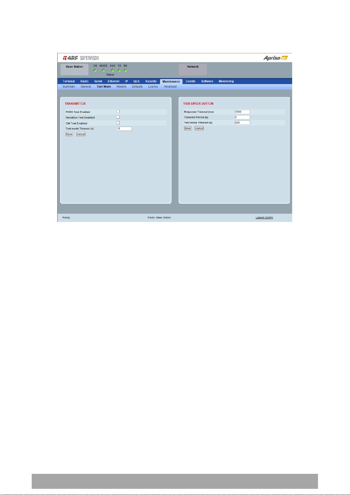
Maintenance > Test Mode
TRANSMITTER
PRBS Test Enabled
When active, the transmitter outputs a continuous PRBS signal. This can be used for evaluating the output
spectrum of the transmitter and verifying adjacent channel power and spurious emission products.
Deviation Test Enabled
When active, the transmitter outputs a sideband tone at the deviation frequency used by the CPFSK
modulator. This can be used to evaluate the local oscillator leakage and sideband rejection performance
of the transmitter.
CW Test Enabled
When active, the transmitter outputs a continuous wave signal. This can be used to verify the frequency
stability of the transmitter.
Test Mode Timeout (s)
This parameter sets the Transmitter Test Mode timeout period. The radio will automatically exit
Transmitter Test Mode after the Timeout period. The default setting is 10 seconds.

Managing the Radio | 211
Aprisa SR+ User Manual 1.6.0 PO
RSSI TEST BUTTON
Response Timeout (ms)
This parameter sets the time RSSI Test Mode waits for a response from the base station before it times out
and retries. The default setting is 3000 ms.
Transmit Period (sec)
This parameter sets the time between RSSI Test Mode requests to the base station. The default setting is
5 seconds.
Test Mode Timeout (s)
This parameter sets the RSSI Test Mode timeout period. The radio will automatically exit RSSI Test Mode
after the Timeout period. The default setting is 600 seconds.

212 | Managing the Radio
Aprisa SR+ User Manual 1.6.0 PO
Option
Function
Enable
Enables the FEC Disable diagnostic function
Disable
Disables the FEC Disable diagnostic function
Timer
Allows the FEC to be disabled but only for a predetermined period.
Maintenance > Modem
Base Station
FEC DISABLE
FEC Disable
This diagnostic function allows the user to temporarily disable forward error correction on the channel
when diagnosing problems on the link.
Therefore, enabling this diagnostic function would temporarily disable FEC on the channel and the
associated maintenance mode alarm would activate.
Note that the opposite is not true for this diagnostic function. In other words, this diagnostic function
does not provide the user with the option to temporarily enable forward error correction on the channel.
All diagnostic functions are not persistent and will be return to disabled states should the system restart.
Duration (s)
This parameter defines the period required for disabling of the FEC. When this period elapses, the FEC is
enabled.

Managing the Radio | 213
Aprisa SR+ User Manual 1.6.0 PO
Option
Function
Disable
Disables manual locking of the adaptive modulation i.e. allows for
automatic adaptive modulation.
Enable
Allows the adaptive modulation to be manually locked
Timer
Allows the adaptive modulation to be manually locked but only for
a predetermined period.
Option
Function
Default
Manually locks the adaptive modulation to the default modulation
defined in ‘Default Modulation’ on page 113.
Current
Manually locks the adaptive modulation to the current modulation
at that time.
Remote Station
ADAPTIVE CODING AND MODULATION
ACM Lock
This parameter sets whether adaptive modulation can be locked or not.
ACM Lock To
This parameter manually locks the adaptive modulation.
Duration (s)
This parameter defines the period required for manually locking the adaptive modulation. When this
period elapses, the adaptive modulation becomes automatic.

214 | Managing the Radio
Aprisa SR+ User Manual 1.6.0 PO
Option
Function
Enable
Enables the FEC Disable diagnostic function
Disable
Disables the FEC Disable diagnostic function
Timer
Allows the FEC to be disabled but only for a predetermined period.
FEC DISABLE
FEC Disable
This diagnostic function allows the user to temporarily disable forward error correction on the channel
when diagnosing problems on the link.
Therefore, enabling this diagnostic function would temporarily disable FEC on the channel and the
associated maintenance mode alarm would activate.
Note that the opposite is not true for this diagnostic function. In other words, this diagnostic function
does not provide the user with the option to temporarily enable forward error correction on the channel.
All diagnostic functions are not persistent and will be return to disabled states should the system restart.
Duration (s)
This parameter defines the period required for disabling of the FEC. When this period elapses, the FEC is
enabled.

Managing the Radio | 215
Aprisa SR+ User Manual 1.6.0 PO
Maintenance > Defaults
DEFAULTS
The Maintenance Defaults page is only available for the local terminal.
Restore Factory Defaults
When activated, all radio parameters will be set to the factory default values. This includes resetting the
radio IP address to the default of 169.254.50.10.
Note: Take care using this command.
Save User Defaults
When activated, all current radio parameter settings will be saved to non-volatile memory within the
radio.
Restore User Defaults
When activated, all radio parameters will be set to the settings previously saved using ‘Save User
Defaults’.

216 | Managing the Radio
Aprisa SR+ User Manual 1.6.0 PO
Part Number
Part Description
APSQ-N400-SSC-HD-22-ENAA
4RF SR+, BR, 400-470 MHz, SSC, Half Duplex, 2E2S, EN, STD
Maintenance > Licence
LICENCE
Fully Featured Radio
When a fully featured Aprisa SR+ radio is purchased (indicated by the AA), it contains the licences which
activate Remote Management, Ethernet Traffic, and SNMP Management e.g.
In this software version, Remote Management, Ethernet Traffic and SNMP management are enabled by
default.
Managing the Radio | 217
Aprisa SR+ User Manual 1.6.0 PO
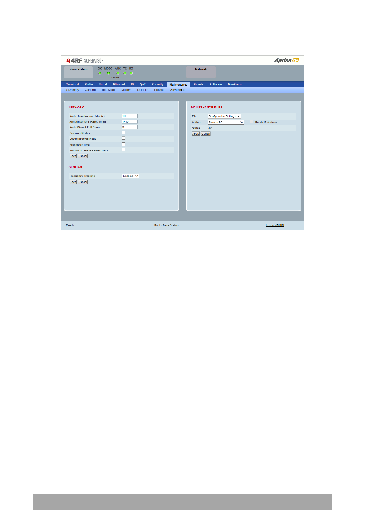
Maintenance > Advanced
NETWORK
Node Registration Retry (sec)
This parameter sets the base station poll time at startup or the remote / repeater station time between
retries until registered. The default setting is 10 seconds.
Base Station Announcement Period (min)
This parameter sets the period between base station polls post startup. The default setting is 1440
minutes (24 hours).
When a new base station powers on, it announces its presence and each remote that receives the
announcement message will be advised that a new base station is present and that they should re-register.
This allows the new base station to populate its Network Table, with knowledge of the nodes in the
network.
If, during this initial period, there is some temporary path disturbance to one or more remotes, they may
miss the initial announcement messages and be left unaware of the base station change. For this reason,
the base station must periodically send out announcement messages to pick up any stray nodes and the
period of these messages is the base station Announcement Period.
Setting this parameter to 0 will stop periodic announcement messages being transmitted.
If a critical parameter is changed in the base station, such as IP address, then the change is distributed to
the network using base station announcement message. Note that in this case, an announcement is sent
immediately independent of the Announcement Period setting.

218 | Managing the Radio
Aprisa SR+ User Manual 1.6.0 PO
Node Missed Poll Count
This parameter sets the number of times the base station attempts to poll the network at startup or if a
duplicate IP is detected when a remote / repeater station is replaced. The default setting is 3.
Discover Nodes
This parameter when activated triggers the base station to poll the network with Node Missed Poll Count
and Node Registration Retry values.
Decommission Node(s)
This parameter when activated resets the network registrations to remove the entire network from
service.
Note: Take care using this option.
Broadcast Time
This parameter when activated sends the base station Date / Time setting to all the remote and repeater
stations in the network and sets their Date / Time. This option applies to the base station only.
Automatic Route Rediscovery
This parameter enables the radio to transmit route discovery messages when packets are unacknowledged.
When enabled, unacknowledged unicast packets are converted into uni-broadcast messages and sent
through the network. All nodes see the message and populate their routing tables accordingly.
When the destination node is reached, it sends a route response message via the shortest path. The
intermediate nodes see this message and populate their routing tables in the reverse direction, thus reestablishing the route.
The default setting is disabled.
GENERAL
Frequency Tracking
Frequency Tracking enables the receiver to track any frequency drift in the transmitter to maintain
optimum SNR and radio link performance over the full temperature range.
When enabled, remote stations adjust their receive frequency to the frequency of the incoming packet
rate and the base station notifies remote stations if their transmit frequency requires adjustment.
The default setting is Enabled.
Managing the Radio | 219
Aprisa SR+ User Manual 1.6.0 PO
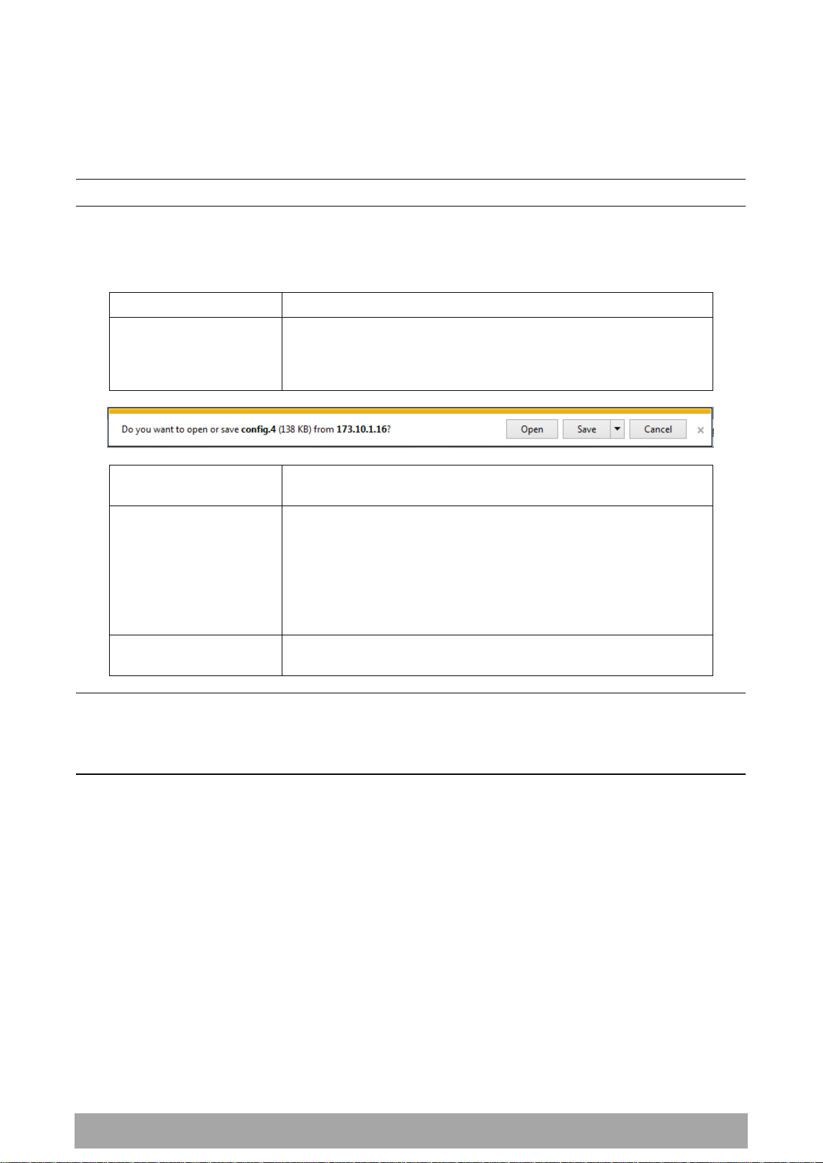
Action
Option
Save to PC
This saves the file with a filename of ‘Config.4’ to a binary
encrypted file. This can then be saved from the Browser popup
(example is Windows Internet Explorer 11). The file should be
renamed to be able to identify the radio it was saved from.
Save to Radio USB
This saves the file with a filename of ‘asrcfg_1.6.0’ to a binary
encrypted file on the radio USB flash drive root directory.
Restore from PC
This restores all user configuration settings from a binary
encrypted file on a PC directory to the radio.
A reboot warning message will warn of a pending reboot after the
PC file is selected. Clicking OK will open a browser file selection
window to select the file.
Note: If you are using Explorer, it must be IE10 or above for this
feature to work correctly.
Restore from Radio USB
This restores all user configuration settings from a binary
encrypted file on the USB root directory to the radio.
MAINTENANCE FILES
There are three maintenance file types which can saved / restored to / from PC or USB flash drive:
Note: Some brands of USB flash drives may not work with 4RF radios.
File - Configuration Settings
Action
Note: ‘Payload Encryption Key’ and ‘Key Encryption Key’ parameters (see ‘Security > Setup’) are not
saved to the configuration file. When a ‘Restore from PC’ or ‘Restore from Radio USB’ is used, these
parameters will retain their existing values so are not changed by the operation of restoring the
configuration file.
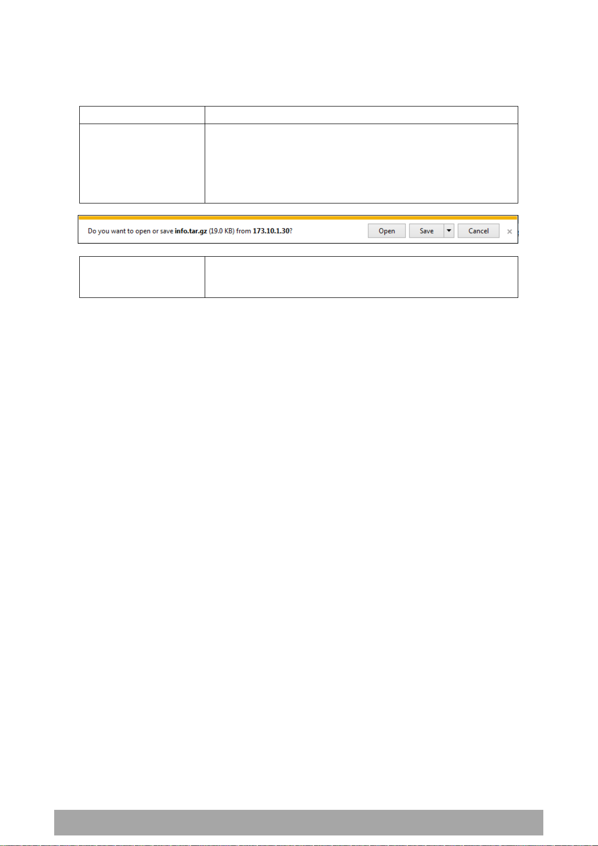
220 | Managing the Radio
Aprisa SR+ User Manual 1.6.0 PO
Action
Option
Save to PC
This saves the file with a filename of ‘Info.tar.gz’ to a binary
encrypted file. This can then be saved from the Browser popup
(example is Windows Internet Explorer 11). The file should be
renamed to be able to identify the radio it was saved from.
The ‘gz’ file is normally for sending back to 4RF Limited for
analysis but can be opened with WinRar.
Save to Radio USB
This saves the file with a filename of e.g.
‘alarm_173.10.1.30_2014-11-10,15.54.14.txt’ to a text file on the
radio USB flash drive root directory.
File - Event History Log
Action

Managing the Radio | 221
Aprisa SR+ User Manual 1.6.0 PO
Action
Option
Load and Execute
This loads and executes configuration script files.
There are sample configuration script files on the product CD in a
directory called ‘Master Configuration’.
The purpose of these files is to use as templates to create your
own configuration scripts.
Note: Be careful using this feature as incompatible configurations
will change the radios settings and break radio connectivity.
File - Configuration Script
Action
Note: Activating this function will over-write all existing configuration settings in the radio (except for the
non-saved settings e.g. security passwords, licence keys etc) without any verification of the command
setting in the radio. Precautions should be taken to prevent radio outages with incorrect radio
configurations. The following process steps are recommended:
a. Save the current radio configuration to a PC or USB before uploading the new configuration script
file
b. Upload the new configuration script file to the radio
c. If for some reason the radio doesn’t work as expected, the saved configuration file can be
uploaded to the radio (roll back to previous configuration).
Retain IP Address
This parameter when enabled ensures that the radio IP address is not changed when the radio
configuration settings are restored from a configuration file with a different IP radio address. It prevents
the radio losing connectivity when the configuration settings are restored from a configuration file.
Revert Config if Connection Lost
When the Maintenance Files feature is used on remote radios from the base station, this parameter allows
the configurations to be restored to the previous configuration if the connection is lost.
This must be set before executing the Configuration Settings / Configuration Script restore functions.

222 | Managing the Radio
Aprisa SR+ User Manual 1.6.0 PO
LED Colour
Severity
Green
No alarm
Orange
Warning alarm
Red
Critical, major or minor alarm
Events
The Events menu contains the setup and management of the alarms, alarm events and traps.
Events > Alarm Summary
There are two types of events that can be generated on the Aprisa SR+ radio. These are:
1. Alarm Events
Alarm Events are generated to indicate a problem on the radio.
2. Informational Events
Informational Events are generated to provide information on key activities that are occurring on the
radio. These events do not indicate an alarm on the radio and are used to provide information only.
See ‘Alarm Types and Sources’ on page 368 for a complete list of events.
ALARM SUMMARY
The Alarm Summary is a display tree that displays the current states of all radio alarms. The alarm states
refresh automatically every 12 seconds.

Managing the Radio | 223
Aprisa SR+ User Manual 1.6.0 PO
Events > Event History
EVENT HISTORY
The last 1500 events are stored in the radio. The complete event history list can be downloaded to a USB
flash drive (see ‘File - Event History Log’ on page 220).
The Event History can display the last 50 events stored in the radio in blocks of 8 events.
The Next button will display the next page of 8 events and the Prev button will display the previous page
of 8 events. Using these buttons will disable Auto Refresh to prevent data refresh and page navigation
contention.
The last 50 events stored in the radio are also accessible via an SNMP command.
Auto Refresh
The Event History page selected will refresh automatically every 12 seconds if the Auto Refresh is ticked.

224 | Managing the Radio
Aprisa SR+ User Manual 1.6.0 PO
Severity
Function
Critical
The Critical severity level indicates that a service affecting condition has occurred and
an immediate corrective action is required. Such a severity can be reported, for
example, when a managed object becomes totally out of service and its capability must
be restored.
Major
The Major severity level indicates that a service affecting condition has developed and
an urgent corrective action is required. Such a severity can be reported, for example,
when there is a severe degradation in the capability of the managed object and its full
capability must be restored.
Minor
The Minor severity level indicates the existence of a non-service affecting fault
condition and that corrective action should be taken in order to prevent a more serious
(for example, service affecting) fault.
Such a severity can be reported, for example, when the detected alarm condition is not
currently degrading the capacity of the managed object.
Warning
The Warning severity level indicates the detection of a potential or impending service
affecting fault, before any significant effects have been felt. Action should be taken to
further diagnose (if necessary) and correct the problem in order to prevent it from
becoming a more serious service affecting fault.
Events > Events Setup
EVENTS SETUP
Alarm event parameters can be configured for all alarm events (see ‘Alarm Events’ on page 369).
All active alarms for configured alarm events will be displayed on the Monitoring pages (see ‘Monitoring’
on page 253).
This Switch and Block parameters are only visible / applicable when the radio is part of a Protected
Station.
Severity
The Severity parameter sets the alarm severity.

Managing the Radio | 225
Aprisa SR+ User Manual 1.6.0 PO
Information
No problem indicated – purely information

226 | Managing the Radio
Aprisa SR+ User Manual 1.6.0 PO
Option
Function
None
Alarm triggers an event trap and is logged in the radio
Traps
Alarm is logged in the radio but does not trigger an event trap
Traps and Log
Alarm neither triggers an event trap nor is logged in the radio
Suppress
This parameter determines if the action taken by an alarm.
Lower Limit / Upper Limit
Threshold alarm events have lower and upper limit settings. The alarm is activated if the current reading
is outside the limits.
Example: 9 RX CRC Errors
The Upper Limit is set to 0.7 and the Duration is set to 5 seconds.
If in any 5 second period, the total number of errored packets divided by the total number of received
packets exceeds 0.7, the alarm will activate.
Units (1)
The Units parameter shows the unit for the Lower Limit and Upper Limit parameters.
Duration
This parameter determines the period to wait before an alarm is raised if no data is received.
Units (2)
This parameter shows the unit for the Duration parameters.
Switch
This parameter determines if the alarm when active causes a switch over of the Protection Switch.
This parameter is only applicable when the radio is part of a Protected Station.
Block
This parameter determines if the alarm is prevented from causing a switch over of the Protection Switch.
This parameter is only applicable when the radio is part of a Protected Station.
The Next button will display the next page of 8 alarm events and the Prev button will display the previous
page of 8 alarm events.

Managing the Radio | 227
Aprisa SR+ User Manual 1.6.0 PO
Option
Function
None
No event related traps are sent.
Event Recorded
When an event is recorded in the event history log, a trap is sent.
Event Updated
When an event is updated in the event history log, a trap is sent.
All Events
When an event is recorded or updated in the event history log, a
trap is sent.
Events > Traps Setup
TRAPS SETUP
All events can generate SNMP traps. The types of traps that are supported are defined in the ‘Notification
Mode’.
Destination Address
This parameter sets the IP address of the server running the SNMP manager.
Port
This parameter sets the port number the server running the SNMP manager.
Community String
This parameter sets the community string which is sent with the IP address for security. The default
community string is ‘public’.
Notification Mode
This parameter sets when an event related trap is sent:

228 | Managing the Radio
Aprisa SR+ User Manual 1.6.0 PO
Option
Function
Standard Trap
Provides a standard SNMP trap event
Inform Request
Provides a SNMP v2 Inform Request trap event including trap retry
and acknowledgement
Notification Type
This parameter sets the type of event notification:
Notification Type set to Inform Request:
Timeout (second)
This parameter sets the time interval to wait for an acknowledgement before sending another retry.
Maximum Retries
This parameter sets the maximum number of retries to send the event without acknowledgement before it
gives up.
Enabled
This parameter determines if the entry is used.

Managing the Radio | 229
Aprisa SR+ User Manual 1.6.0 PO
Events > Alarm I/O Setup
ALARM PORTS
This page provides control of the two hardware alarm inputs and two hardware alarm outputs provided on
the alarm connector.
The alarm inputs are used to transport alarms to the other radios in the network. The alarm outputs are
used to receive alarms from other radios in the network.
These alarms are only available when the station is non protected.
Name
The alarm IO number.
Type
The Type shows if the alarm is an input or output.
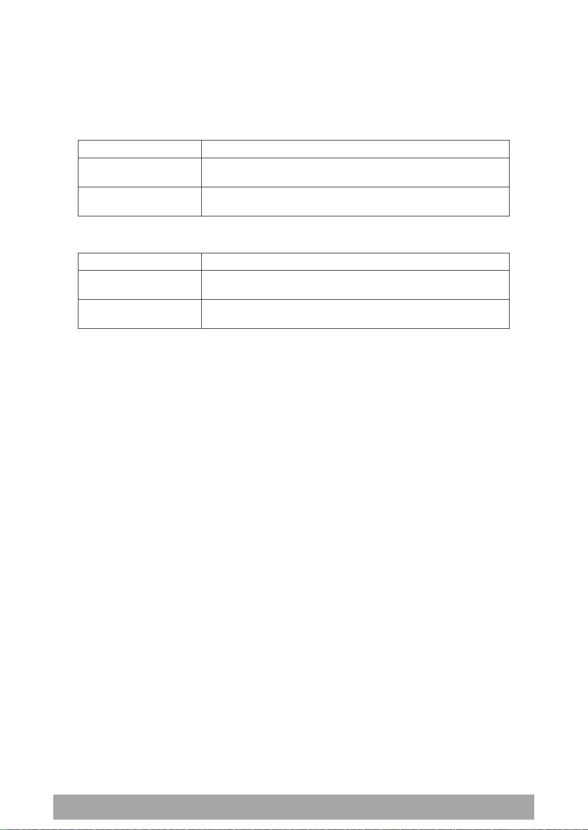
230 | Managing the Radio
Aprisa SR+ User Manual 1.6.0 PO
Option
Function
Low
The alarm is active low i.e. a ground contact on the port will cause
an active alarm state
High
The alarm is active high i.e. an open contact on the port will cause
an active alarm state
Option
Function
Low
The alarm is active low i.e. the active alarm state will generate a
ground contact output
High
The alarm is active high i.e. the active alarm state will generate a
open contact output
Active State
The Active State parameter sets the alarm state when the alarm is active.
Alarm Input
Alarm Output
Current State
The Current State shows the current state of the alarm.

Managing the Radio | 231
Aprisa SR+ User Manual 1.6.0 PO
Option
Function
None
This action setup does not activate any alarm output
Activate Alarm Output 1
This action setup activates alarm output 1
Activate Alarm Output 2
This action setup activates alarm output 2
Events > Event Action Setup
EVENT ACTION SETUP
This page provides control of the mapping of events to specific actions. Specific alarm events can setup to
trigger outputs.
Action Definition
This parameter shows the number of the event action setup and the maximum number of setups stored.
Action Destination IP Address
This parameter sets the IP address of the radio that will output the action type.
Action Type
This parameter sets the action type that will be activated on the radio.

232 | Managing the Radio
Aprisa SR+ User Manual 1.6.0 PO
Option
Function
None
No action output.
Radio Severity Equal Critical
Activates the action output when a radio alarm is critical
alarm
Radio Severity Equal Major
Activates the action output when a radio alarm is a major
alarm
Radio Severity Equal Minor
Activates the action output when a radio alarm is minor
alarm
Radio Severity Equal Warning
Activates the action output when a radio alarm is a
warning alarm
Radio Severity Equal Cleared
Activates the action output when a radio alarm is cleared
Radio Severity Equal or Worse than
Major
Activates the action output when a radio alarm is a major
alarm or a critical alarm
Radio Severity Equal or Worse than
Minor
Activates the action output when a radio alarm is a minor
alarm, a major alarm or a critical alarm
Radio Severity Equal or Worse than
Warning
Activates the action output when a radio alarm is a
warning, a major alarm, a minor alarm or a critical alarm
Action Threshold Criteria
This parameter sets the radio event that will trigger the action output.
Controls
The Save button saves the current event action setup.
The Cancel button cancels the new event action setup.
The Add button adds a new event action setup.
The Delete button deletes the current event action setup.
The Clear Map button clears all alarm selections on the current setup.
To add an event action setup:
1. Click on the Add button.
2. Enter the Action Destination IP Address. This is the IP address of the radio that will output the action
type.
3. Select the Action Type from the list.
4. Select the Action Threshold Criteria from the list.
5. Tick the alarms required for the event action setup from the Action Alarm Map. You can clear all
alarm selections with the Clear Map button.
6. Click on Save.

Managing the Radio | 233
Aprisa SR+ User Manual 1.6.0 PO
Events > Defaults
EVENT DEFAULTS
Restore Defaults
This parameter when activated restores all previously configured event parameters using ‘Events > Events
Setup’ to the factory default settings.

234 | Managing the Radio
Aprisa SR+ User Manual 1.6.0 PO
Software
The Software menu contains the setup and management of the system software including network
software distribution and activation. The distribution of the system software to the remote radios is
encrypted by the AES session key over-the-air.
Single Radio Software Upgrade
The radio software can be upgraded on a single Aprisa SR+ radio (see ‘Single Radio Software Upgrade’ on
page 362). This process would only be used if the radio was a replacement or a new station in an existing
network.
Network Software Upgrade
The radio software can be upgraded on an entire Aprisa SR+ radio network remotely over the radio link
(see ‘Network Software Upgrade’ on page 358). This process involves following steps:
1. Transfer the new software to base station with ‘Software > File Transfer’
2. Distribute the new software to all remote stations with ‘Software > Remote Distribution’
3. Activate of the new software on remote stations with ‘Software > Remote Activation’.
4. Finally, activate the new software on the base station radio with ‘Software > Manager’. Note:
activating the software will reboot the radio.

Managing the Radio | 235
Aprisa SR+ User Manual 1.6.0 PO
Software > Summary
This page provides a summary of the software versions installed on the radio, the setup options and the
status of the File Transfer.
SOFTWARE VERSIONS
Current Version
This parameter displays the software version running on the radio.
Previous Version
This parameter displays the software version that was running on the radio prior to the current software
being activated.
Software Pack Version
On the base station, this parameter displays the software version available for distribution to all radios in
the network.
On the all stations, this parameter displays the software version ready for activation.
USB AUTOMATIC UPGRADE
USB Boot Upgrade
This parameter shows the type of USB Boot upgrade defined in ‘Software Setup > USB Boot Upgrade’ on
page 237.

236 | Managing the Radio
Aprisa SR+ User Manual 1.6.0 PO
FILE TRANSFER
Transfer Activity
This parameter shows the status of the transfer, ‘Idle’, ‘In Progress’ or ‘Completed’.
Method
This parameter shows the file transfer method. When the software distribution is in progress, this
parameter will change to ‘Over the Air’ (from xx.xx.xx.xx) to show that the interface is busy and the
transfer is in progress.
File
This parameter shows the software file source.
Transfer Result
This parameter shows the progress of the transfer.

Managing the Radio | 237
Aprisa SR+ User Manual 1.6.0 PO
Option
Function
Load and Activate
New software will be uploaded from a USB flash drive in to the
Aprisa SR+ when the radio is power cycled and activated
automatically.
Load Only
New software will be uploaded from a USB flash drive in to the
Aprisa SR+ when the radio is power cycled. The software will need
to be manually activated (see ‘Software > Manager’ on page 242).
Disabled
Software will not be uploaded from a USB flash drive into the
Aprisa SR+ when the radio is power cycled.
Software > Setup
This page provides the setup of the USB flash drive containing a Software Pack.
USB SETUP
USB Boot Upgrade
This parameter determines the action taken when the radio power cycles and finds a USB flash drive in the
Host port. The default setting is ‘Load and Activate’.
Note: This parameter must be set to ‘Disabled’ if the ‘File Transfer and Activate’ method of upgrade is
used. This ‘Disabled’ setting prevents the radio from attempting another software upload when the radio
boots (which it does automatically after activation).
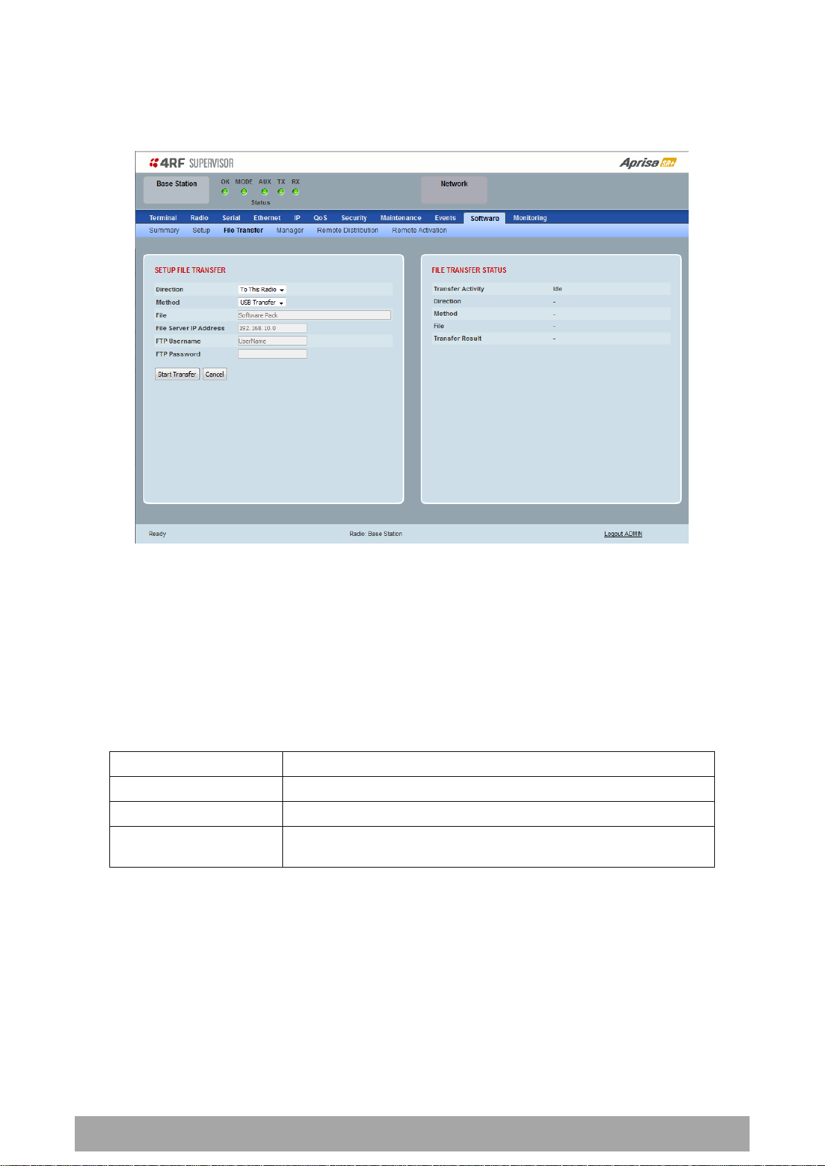
238 | Managing the Radio
Aprisa SR+ User Manual 1.6.0 PO
Option
Function
USB Transfer
Transfers the software from the USB flash drive to the radio.
FTP
Transfers the software from an FTP server to the radio.
HTTP / HTTPS
Transfers the software directly from a PC software pack file to the
radio.
Software > File Transfer
This page provides the mechanism to transfer new software from a file source into the radio.
SETUP FILE TRANSFER
Direction
This parameter sets the direction of file transfer. In this software version, the only choice is ‘To the
Radio’.
Method
This parameter sets the method of file transfer.
File
This parameter shows the software file source.
FTP Username
This parameter sets the Username to access the FTP server.
FTP Password
This parameter sets the Password to access the FTP server.

Managing the Radio | 239
Aprisa SR+ User Manual 1.6.0 PO
Transfer Result
Function
Starting Transfer
The transfer has started but no data has transferred.
In Progress (x %)
The transfer has started and has transferred x % of the data.
Successful
The transfer has finished successfully.
File Error
The transfer has failed.
Possible causes of failure are:
Is the source file available e.g. USB flash drive plugged in
Does the file source contain the Aprisa SR+ software
release files;
FILE TRANSFER STATUS
Transfer Activity
This parameter shows the status of the transfer, ‘Idle’, ‘In Progress’ or ‘Completed’.
Direction
This parameter shows the direction of file transfer. In this software version, the only choice is ‘To The
Radio’.
Method
This parameter shows the file transfer method.
File
This parameter shows the software file source.
Transfer Result
This parameter shows the progress of the transfer:

240 | Managing the Radio
Aprisa SR+ User Manual 1.6.0 PO
To transfer software into the Aprisa SR+ radio:
USB Transfer Method
1. Unzip the software release files in to the root directory of a USB flash drive.
2. Insert the USB flash drive into the host port .
3. Click on ‘Start Transfer’.
4. When the transfer is completed, remove the USB flash drive from the host port. If the SuperVisor ‘USB
Boot Upgrade’ setting is set to ‘Disabled’ (see ‘USB Boot Upgrade’ on page 237), the USB flash drive
doesn’t need to be removed as the radio won’t try to load from it.
Go to Supervisor > Software > Manager and activate the Software Pack (see ‘Software > Manager’ on page
242). The radio will reboot automatically.
If the file transfer fails, check the Event History page (see ‘Events > Event History’ on page 223) for more
details of the transfer.
Note: Some brands of USB flash drives may not work with 4RF radios.
FTP Method
1. Unzip the software release files in to a temporary directory.
2. Open the FTP server and point it to the temporary directory.
3. Enter the FTP server IP address, Username and password into SuperVisor.
4. Click on ‘Start Transfer’.
Go to Supervisor > Software > Manager and activate the Software Pack (see ‘Software > Manager’ on page
242). The radio will reboot automatically.
If the file transfer fails, check the Event History page (see ‘Events > Event History’ on page 223) for more
details of the transfer.

Managing the Radio | 241
Aprisa SR+ User Manual 1.6.0 PO
HTTP / HTTPS Method
1. Unzip the software release files in to a temporary directory.
2. Click on ‘Start Transfer’.
3. Browse to the *.swpack file in the temporary directory and open the file.
Go to Supervisor > Software > Manager and activate the Software Pack (see ‘Software > Manager’ on page
242). The radio will reboot automatically.
If the file transfer fails, check the Event History page (see ‘Events > Event History’ on page 223) for more
details of the transfer.
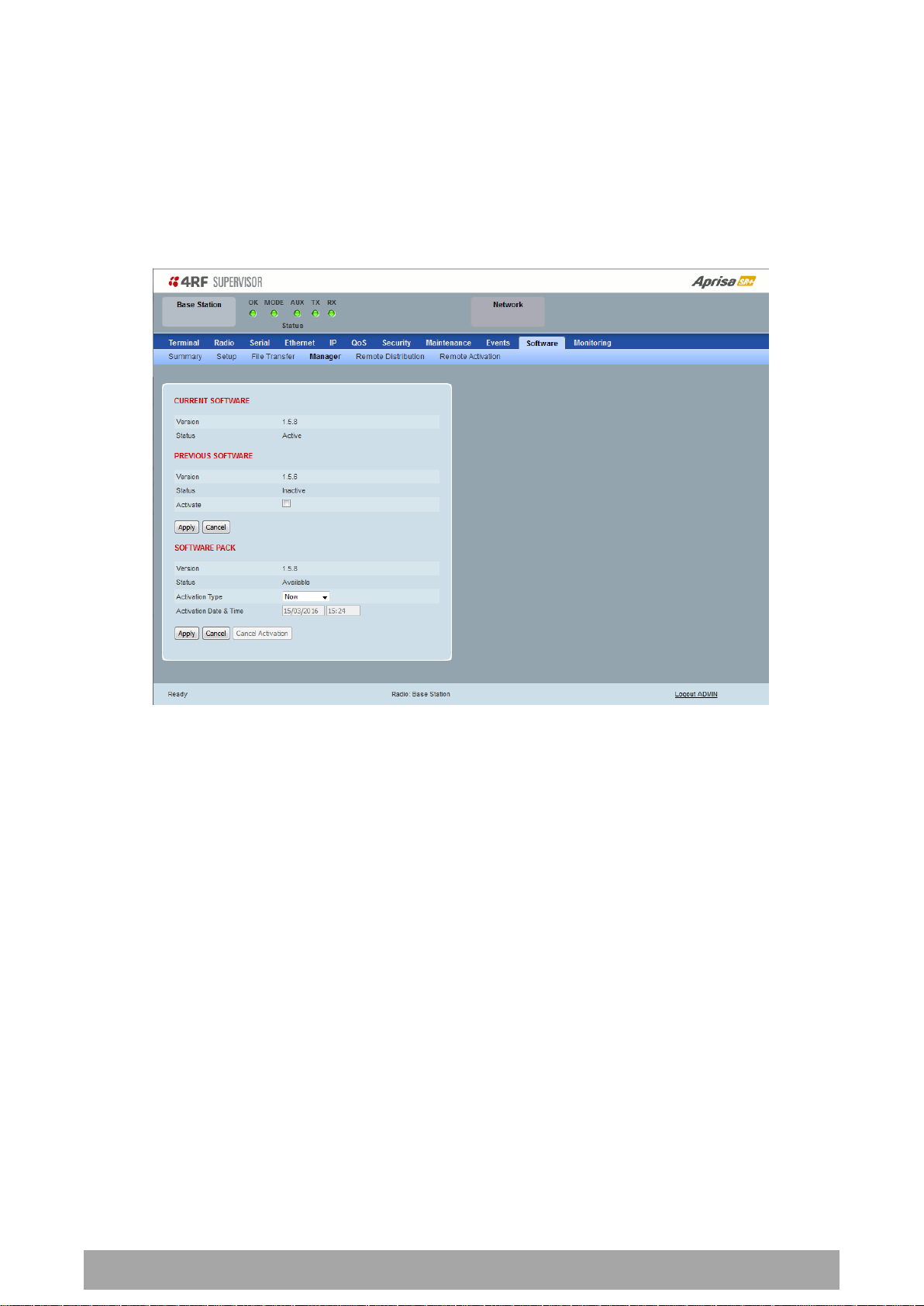
242 | Managing the Radio
Aprisa SR+ User Manual 1.6.0 PO
Software > Manager
This page summarises and manages the software versions available in the radio.
The manager is predominantly used to activate new software on single radios. Network activation is
performed with ‘Software > Remote Activation’.
Both the previous software (if available) and Software Pack versions can be activated on the radio from
this page.
CURRENT SOFTWARE
Version
This parameter displays the software version running on the radio.
Status
This parameter displays the status of the software version running on the radio (always active).

Managing the Radio | 243
Aprisa SR+ User Manual 1.6.0 PO
Option
Function
Active
The software is operating the radio.
Inactive
The software is not operating the radio but could be re-activated if
required.
Option
Function
Available
On the base station, the software pack is available for distribution.
On all stations, the software pack is available for activation.
Activating
The software pack is activating in the radio.
Unavailable
There is no software pack loaded into the radio.
Option
Function
Now
Activates the software pack now.
Date & Time
Activates the software pack at the Date & Time set in the following
parameter.
PREVIOUS SOFTWARE
Version
This parameter displays the software version that was running on the radio prior to the current software
being activated.
Status
This parameter displays the status of the software version that was running on the radio prior to the
current software being activated.
Activate
This parameter activates the previous software version (restores to previous version).
The Aprisa SR+ will automatically reboot after activation.
SOFTWARE PACK
Version
This parameter displays the software pack version available for distribution on base station and activate
on all stations.
Status
This parameter displays the status of the software pack version.
Activate
This parameter activates the software pack.
The Aprisa SR+ will automatically reboot after activation.
Activation Type
This parameter sets when the software pack activation will occur.

244 | Managing the Radio
Aprisa SR+ User Manual 1.6.0 PO
Activation Date & Time
This parameter sets the Date & Time when the software pack activation will occur.
This setting can be any future date and 24 hour time.
If the network base station radio date / time is not synchronized, you will get the following popup:
You can manually enter the base station radio date / time or use the Date And Time Synchronization from
a SNTP server feature (see ‘Terminal > Date / Time’ on page 92).

Managing the Radio | 245
Aprisa SR+ User Manual 1.6.0 PO
To activate a software version:
1. Tick the software version required to be activated (previous software or software pack).
2. Click ‘Apply’.
The page will display a Status of ‘Activating’.
Once started, activation cannot be cancelled.
When the activation is completed, the radio will reboot. This will cause the current SuperVisor session to
expire.
3. Login to SuperVisor to check the result.

246 | Managing the Radio
Aprisa SR+ User Manual 1.6.0 PO
Software > Remote Distribution
This page provides the mechanism to distribute software to all remote stations into the Aprisa SR+
network (network) and then activate it.
The Software Pack that was loaded into the base station with the file transfer process (see ‘Software >
File Transfer’ on page 238) can be distributed via the radio link to all remote stations.
This page is used to manage the distribution of that software pack to all remote radios on the network.
This page is only available when the radio is configured as a Base Station.
REMOTE SOFTWARE DISTRIBUTION
Software Pack Version
This parameter displays the software pack version available for distribution on base station and activate
on all stations.
Status
This parameter displays the status of the software pack version.
If a Software Pack is not available, the status will display ‘Unavailable’ and the software distribution
mechanism will not work.

Managing the Radio | 247
Aprisa SR+ User Manual 1.6.0 PO
Start Transfer
This parameter when activated distributes (broadcasts) the new Software Pack to all remote stations in
the network.
Note: The distribution of software to remote stations does not stop customer traffic from being
transferred. However, due to the volume of traffic, the software distribution process may affect customer
traffic.
Software distribution traffic is classified as ‘management traffic’ but does not use the Ethernet
management priority setting. Software distribution traffic priority has a fixed priority setting of ‘very
low’.
To distribute software to remote stations:
This process assumes that a Software Pack has been loaded into the base station with the file transfer
process (see ‘Software > File Transfer’ on page 238).
1. To ensure that the Network Table is up to date, it is recommended running the node discover function
(see ‘Discover Nodes’ on page 218).
2. Click on ‘Start Transfer’.
Note: This process could take anywhere between 40 minutes and several hours depending on channel size,
Ethernet Management Priority setting and the amount of customer traffic on the network.
3. When the distribution is completed, activate the software with the Remote Software Activation.
Pause Transfer
This parameter when activated, pauses the distribution process and shows the distribution status. The
distribution process will continue from where it was paused with Resume Transfer.
Cancel Transfer
This parameter when activated, cancels the distribution process immediately.
During the distribution process, it is possible to navigate away from this page and come back to it to check
progress. The SuperVisor session will not timeout.

248 | Managing the Radio
Aprisa SR+ User Manual 1.6.0 PO
Option
Function
Now
Activates the software pack now.
Date & Time
Activates the software pack at the Date & Time set in the following
parameter.
Software > Remote Activation
This page provides the mechanism to activate software on all remote stations.
The Software Pack was loaded into the base station with the file transfer process (see ‘Software > File
Transfer’ on page 238) and was distributed via the radio link to all remote stations.
This page is used to manage the activation of that software pack on all remote radios on the network.
This page is only available when the radio is configured as a Base Station.
REMOTE SOFTWARE ACTIVATION
When the software pack version has been distributed to all the remote stations, the software is then
activated in all the remote stations with this command. If successful, then activate the software pack in
the base station to complete the network upgrade.
Version
This parameter displays the software version for activation. The default version is the software pack
version but any valid software version can be entered in the format ‘n.n.n’.
Activation Type
This parameter sets when the software pack activation will occur.
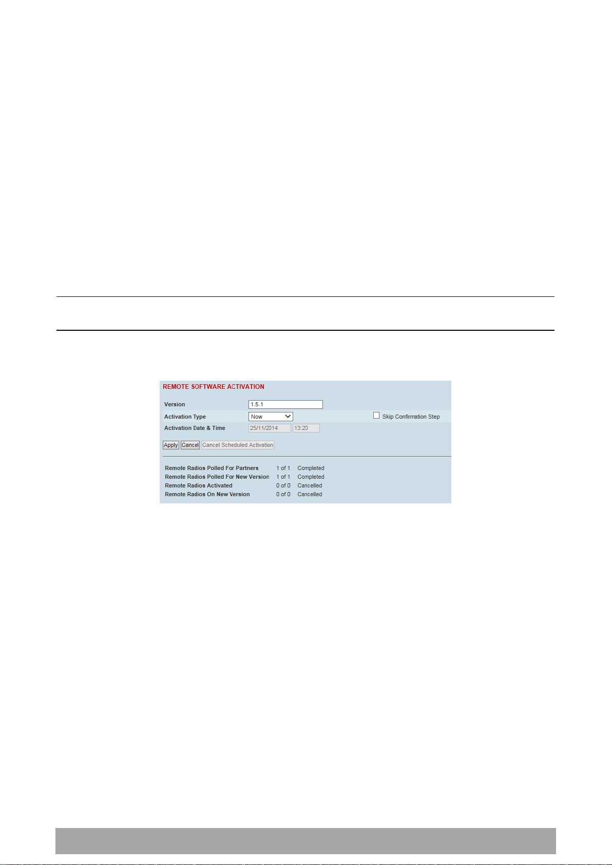
Managing the Radio | 249
Aprisa SR+ User Manual 1.6.0 PO
Activation Date & Time
This parameter sets the Date & Time when the software pack activation will occur.
This setting can be any future date and 24 hour time.
Skip Confirmation Step
This parameter when enabled skips the confirmation step during the activation process.
Normally, the confirmation step will require use intervention to accept the confirmation which will halt
the activation process. Skipping the confirmation will enable the activation process to continue without
use intervention.
To activate software in remote stations:
This process assumes that a Software Pack has been loaded into the base station with the file transfer
process (see ‘Software > File Transfer’ on page 238) and distributed to all remote radios in the network.
Note: Do not navigate SuperVisor away from this page during the activation process (SuperVisor can lose
PC focus).
1. Enter the Software Pack version (if different from displayed version).
2. Select the Activation type.
3. Click Apply.

250 | Managing the Radio
Aprisa SR+ User Manual 1.6.0 PO
Result
Function (X of Y)
Remote Radios Polled for
Partners
X is the number of radios polled to determine the number of
protected stations in the network.
Y is the number of remote radios registered with the base station.
Remote Radios Polled for
New Version
X is the number of radios polled to determine the number of radios
that contain the new software version.
Y is the number of remote radios registered with the base station.
Remote Radios Activated
X is the number of radios that contain the new software version
and have been activated.
Y is the number of radios that contain the new software version
and can be activated.
Remote Radios On New
Version
X is the number of radios that has been successfully activated and
now running the new version of software.
Y is the number of radios that the activation command was
executed on.
Note: When upgrading from software version 1.2.5 to 1.2.6 or
later, communication to all remote radios will be lost due to a MAC
protocol change. This will prevent this function from working
correctly. In this case, activate the new software on the base
station and run the ‘Maintenance > Advanced’ Discover Nodes
function on page 217.
The remote stations will be polled to determine which radios require activation:
When the activation is ready to start:
4. Click on ‘OK’ to start the activation process or Cancel to quit.

Managing the Radio | 251
Aprisa SR+ User Manual 1.6.0 PO
The page will display the progress of the activation.
The example shows that during the activation process there were exceptions that may need to be
investigated.
When all the remote radios have been activated, the base station radio must now be activated with (see
‘Software > Manager’ on page 242).
4. Click on ‘OK’ to start the activation on the base station.

252 | Managing the Radio
Aprisa SR+ User Manual 1.6.0 PO
Option
Function
Now
Activates the remote software now.
Date & Time
Activates the remote software at the Date & Time set in the
following parameter.
Activation Type
This parameter sets when the remote software activation will occur.
Skip Confirmation Step
This parameter when enabled skips the confirmation step during the activation process.
Normally, the confirmation step will require use intervention to accept the confirmation which will halt
the activation process. Skipping the confirmation will enable the activation process to continue without
use intervention.
Activation Date & Time
This parameter sets the Date & Time when the remote software activation will occur.
This setting can be any future date and 24 hour time.
When the date and time is set, the remotes will be polled to setup the scheduled activation date and
time.
If the network base station radio date / time is not synchronized, you will get the following popup:
You can manually enter the base station radio date / time or use the Date And Time Synchronization from
a SNTP server feature (see ‘Terminal > Date / Time’ on page 92).

Managing the Radio | 253
Aprisa SR+ User Manual 1.6.0 PO
Monitored Parameter
Function
Normal Operating Limits
Current VDC Power Supply
Parameter to show the current power
supply input voltage
10 to 30 VDC
Current 3.3 Volts Power
Supply
Parameter to show the current 3.3 volt
power rail voltage
3.1 to 3.5 VDC
Current 5.0 Volts Power
Supply
Parameter to show the current that the
current 5.0 volt power rail voltage
4.7 to 5.5 VDC
Current 7.2 Volts Power
Supply
Parameter to show the current that the
current 7.2 volt power rail voltage
6.9 to 7.5 VDC
Current 15 Volts Power
Supply
Parameter to show the current that the
current 15 volt power rail voltage.
The 15 volt power supply is used to power
the transmitter driver and power amplifier.
320, 400 and 450 MHz
14.5 to 15.3 VDC
135, 220, 896 and 928 MHz
12.7 to 13.5 VDC
Monitoring
The Terminal, Serial, Ethernet, Radio and User Selected Monitored Parameter results have history log
views for both Quarter Hourly and Daily.
Monitored parameter data is accumulated into 2 sets:
15 minutes of data, for 96 readings for the last 24 hours
24 hours of data, for 31 readings for the last 31 days.
Monitoring > Terminal
This page displays the current radio internal and external input source radio power supply voltage
diagnostic parameters.
POWER SUPPLY PARAMETERS

254 | Managing the Radio
Aprisa SR+ User Manual 1.6.0 PO
Controls
The History Quarter Hourly button presents a log of results every quarter of an hour.
The History Daily button presents a log of results every day.

Managing the Radio | 255
Aprisa SR+ User Manual 1.6.0 PO
Monitored Parameter
Function
Normal Operating Limits
Maximum Capacity
Parameter to show the maximum serial
data rate of the serial port
Equal to the serial port baud rate setting
Packets Transmitted
Parameter to show the number of packets
transmitted to the customer from the serial
port
Packets Received
Parameter to show the number of packets
received from the customer into the serial
port
Bytes Received
Parameter to show the number of bytes
received from the customer into the serial
port
Errored Bytes Received
Parameter to show the number of bytes
received from the customer into the serial
port that have errors
Dropped Bytes (Congestion)
Parameter to show the number of bytes
received from the customer into the serial
port that are dropped due to over the air
congestion
Monitoring > Serial
This page displays the current radio performance monitoring parameters per serial port in packet and byte
level granularity, for serial port high level statistics and troubleshooting.
The results shown are since the page was opened and are updated automatically every 12 seconds.
SERIAL PORT PARAMETERS
All Serial Ports
Controls
The Reset button clears the current results.
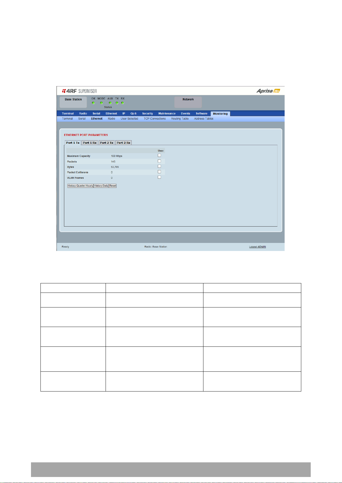
256 | Managing the Radio
Aprisa SR+ User Manual 1.6.0 PO
Monitored Parameter
Function
Normal Operating Limits
Maximum Capacity
Parameter to show the maximum Ethernet
data rate of the Ethernet port
Equal to the Ethernet port speed setting
Packets
Parameter to show the number of packets
transmitted to the customer from the
Ethernet port
Bytes
Parameter to show the number of bytes
transmitted to the customer from the
Ethernet port
Packet Collisions
Parameter to show the number of packet
collisions on the data transmitted to the
customer from the Ethernet port on a
shared LAN
VLAN Frames
Parameter to show the number of VLAN
tagged frames transmitted to the customer
from the Ethernet port
Monitoring > Ethernet
This page displays the current radio performance monitoring parameters per Ethernet port transmission
(TX) out of the radio in packet and byte level granularity, for Ethernet port high level statistics and
troubleshooting.
The results shown are since the page was opened and are updated automatically every 12 seconds.
ETHERNET PORT PARAMETERS
All Ethernet Ports TX
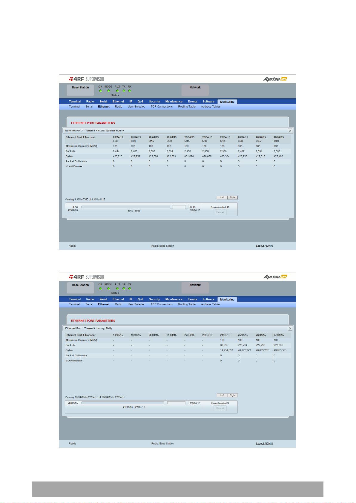
Managing the Radio | 257
Aprisa SR+ User Manual 1.6.0 PO
Controls
The Reset button clears the current results.
The History Quarter Hourly button presents a log of results every quarter of an hour.
The History Daily button presents a log of results every day.

258 | Managing the Radio
Aprisa SR+ User Manual 1.6.0 PO
Monitored Parameter
Function
Packets
Parameter to show the number of packets received by the customer from the Ethernet
port (including bad packets, broadcast packets, and multicast packets)
Bytes
Parameter to show the number of bytes received (including those in bad packets) by the
customer from the Ethernet port (excluding framing bits but including FCS octets)
Packets equal to 64 bytes
Parameter to show the number of packets received (including bad packets) from the
customer into the Ethernet port that are equal to 64 bytes (excluding framing bits but
including FCS octets)
Packets 65 to 127 bytes
Parameter to show the number of packets received (including bad packets) from the
customer into the Ethernet port that are between 65 and 127 bytes (excluding framing
bits but including FCS octets)
Packets 128 to 255 bytes
Parameter to show the number of packets received (including bad packets) from the
customer into the Ethernet port that are between 128 and 255 bytes (excluding framing
bits but including FCS octets)
Packets 256 to 511 bytes
Parameter to show the number of packets received (including bad packets) from the
customer into the Ethernet port that are between 256 and 511 bytes(excluding framing
bits but including FCS octets)
Packets 512 to 1023 bytes
Parameter to show the number of packets received (including bad packets) from the
customer into the Ethernet port that are between 512 and 1023 bytes(excluding framing
bits but including FCS octets)
Packets 1024 to 1536 bytes
Parameter to show the number of packets received (including bad packets) from the
customer into the Ethernet port that are between 1024 and 1536 bytes(excluding framing
bits but including FCS octets)
Broadcast Packets
Parameter to show the number of broadcast packets received from the customer into the
Ethernet port. Broadcast packets are good packets received that were directed to the
broadcast address. Note that this does not include multicast packets.
This page displays the current radio performance monitoring parameters per Ethernet port received (RX)
data in packet and byte level granularity, for Ethernet port high level statistics and troubleshooting.
The results shown are since the page was opened and are updated automatically every 12 seconds.
ETHERNET PORT PARAMETERS
All Ethernet Ports RX

Managing the Radio | 259
Aprisa SR+ User Manual 1.6.0 PO
Monitored Parameter
Function
Multicast Packets
Parameter to show the number of multicast packets received from the customer into the
Ethernet port. Multicast packets are packets that were directed to a multicast address.
Note that this number does not include packets directed to the broadcast address.
VLAN Frames
Parameter to show the number of VLAN tagged frames received from the customer into
the Ethernet port
VLAN Frames Dropped
Parameter to show the number of VLAN tagged frames received from the customer into
the Ethernet port that were dropped due to CRC errored frames, filtered VLAN frames,
undersized frames or oversized frames.
Packet In Error
Parameter to show the number of errored packets received from the customer into the
Ethernet port caused by CRC errors, FCS Errors, alignment errors, oversized packets,
undersized packets, fragmented packets and jabber packets
Bytes In Error
Parameter to show the number of errored bytes received from the customer into the
Ethernet port
CRC / Alignment Error
Parameter to show the number of CRC / alignment errors received from the customer into
the Ethernet port. CRC / alignment errors are defined as frames that had a length
excluding framing bits, but including FCS octets of between 64 and 1518 octets, inclusive,
but had either a bad Frame Check Sequence (FCS) with an integral number of octets (FCS
Error) or a bad FCS with a non-integral number of octets.
Undersized Packets
Parameter to show the number of undersized packets received from the customer into the
Ethernet port. Undersized packets are less than 64 octets long excluding framing bits, but
including FCS octets.
Oversized Packets
Parameter to show the number of oversized packets received from the customer into the
Ethernet port. Oversized packets are longer than 1518 octets excluding framing bits, but
including FCS octets.
Fragmented Packets
Parameter to show the number of fragmented packets received from the customer into
the Ethernet port. Fragmented packets have either a bad Frame Check Sequence (FCS)
with an integral number of octets (FCS Error) or a bad FCS.
Jabber Packets
Parameter to show the number of jabber packets received from the customer into the
Ethernet port
Dropped Packets
(congestion)
Parameter to show the number of dropped packets received from the customer into the
Ethernet port caused by congestion
Dropped Packets (filtering)
Parameter to show the number of dropped packets received from the customer into the
Ethernet port caused by packet L2 / L3 filtering
Dropped Bytes (filtering)
Parameter to show the number of dropped bytes received from the customer into the
Ethernet port caused by packet L2 / L3 filtering
 Loading...