


98 | Managing the Radio
Aprisa SR User Manual
Packet Size (Bytes)
This parameter sets the maximum over-the-air packet size in bytes. A smaller maximum Packet Size is
beneficial when many remote stations or repeater stations are trying to access the channel. The default
setting is 1550 bytes.
As radios dispatched from the factory have a Packet Size set to the maximum value of 1550 bytes, if a new
radio is installed in an existing Field Access Network (network), the Packet Size must be changed to ensure
it is the same value for all radios in the network. The new radio will not register an existing network if the
Packet Size is not the same as the other radios in the network.
This packet size includes the wireless protocol header and security payload (0 to 16 bytes). The length of
the security header depends on the level of security selected.
When the security setting is 0, the maximum user data transfer over-the-air is 1516 bytes.
When encryption is enabled, the entire packet of user data (payload) is encrypted. If authentication is
being used, the security frame will be added (up to 16 bytes). The wireless protocol header is then added
which is proprietary to the Aprisa SR. This is not encrypted.
Packet Time to Live (ms)
This Time To Live (TTL) parameter sets the time a packet is allowed to live in the system before being
dropped if it cannot be transmitted over the air. It is used to prevent old, redundant packets being
transmitted through the Aprisa SR network. The default setting is 1500 ms.
In the case of serial poll SCADA networks such as MODBUS and IEC 60870.50.101, it is important to ensure
the replies from the RTU are in the correct sequence and are not timed out replies from Master requests.
If the TTL value is too long, the SCADA master will detect sequence errors.
It is recommended to use a TTL which is half the serial SCADA timeout. This is commonly called the ‘scan
timeout’ or ‘link layer time out’ or ‘retry timeout’.
When using TCP protocols, a TTL of 1500 ms is recommended because a TCP re-transmission usually occurs
after approximately 3 second.
In SCADA networks which use both serial and Ethernet, it is recommended that the TTL is set to half the
serial SCADA timeout for serial remotes, and 1500 ms for Ethernet (TCP) remotes. For example, if the
serial SCADA timeout is 1000 ms, a remote radio which is connected to the serial RTU should be set to
500 ms, a remote radio which is connected to a Ethernet (TCP) RTU should have a 1500 ms timeout.
In this case, the base station TTL should be set to 1500 ms as well; or which ever is the longer TTL of
serial or Ethernet.

Managing the Radio | 99
Aprisa SR User Manual
Option
Function
Disabled
Every packet received by the radio will be forwarded to the
relevant interface.
Automatic
The radio will filter (discard) packets not destined for itself
according to the Aprisa SR traffic protocols
Option
Function
Broadcast
Serial port traffic from the network is broadcast on all serial ports
on this radio. This will include the RS-232 port derived from the
USB port.
Segregate
Serial port traffic from the network from a specific port number is
directed to the respective serial port only.
Packet Filtering
Each Aprisa SR radio can filter packets not destined for itself. The Packet Filtering parameter controls this
functionality.
In an Aprisa SR network, all communication from remote stations is destined for the base station in the
Aprisa SR network communication protocol. In a repeater network, a remote station will send a message
to the base station. The repeater station will receive this and then repeat the message. The repeated
message will then be received by the base station. Other remote stations connected to the repeater
station will receive this message and depending on the Packet Filtering parameter, either forward this
packet or discard it.
This filtering capability can provide the ability for remote stations to communicate with each other when
connected to a repeater, particularly useful in the event of losing communication with a SCADA Master,
assuming the Aprisa SR network is still operational.
Note: IP Header Compression must be disabled for this feature to operate correctly (see ‘IP Header
Compression Ratio’ on page 101).
The default setting is Automatic.
Note: The Aprisa SR network is transparent to the protocol being transmitted; therefore the Packet
Filtering parameter is based on the Aprisa SR addressing and network protocols, not the user (SCADA, etc.)
traffic protocols.
Serial Data Stream Mode
This parameter controls the traffic flow in the radio serial ports.
The default setting is Broadcast.

100 | Managing the Radio
Aprisa SR User Manual
TRAFFIC SETTINGS
Serial Data Priority
The Serial Data Priority controls the priority of the serial customer traffic relative to the Ethernet
customer traffic. If equal priority is required to Ethernet traffic, this setting must be the same as the
Ethernet Data Priority setting (see ‘Ethernet Data Priority’ on page 100).
The serial data priority can be set to Very High, High, Medium and Low. The default setting is Very High.
A queuing system is used to prioritize traffic from the serial and Ethernet interfaces for over the air
transmission. A weighting may be given to each data type and this is used to schedule the next
transmission over the air e.g. if there are pending data packets in multiple buffers but serial data has a
higher weighting it will be transmitted first. The serial buffer is 20 serial packets (1 packet can be up to
512 bytes).
There are four priority queues in the Aprisa SR: Very High, High, Medium and Low. Data is added to one of
these queues depending on the priority setting. Data leaves the queues from highest priority to lowest:
the Very High queue is emptied first, followed by High then Medium and finally Low.
Ethernet Data Priority
The Ethernet Data Priority controls the priority of the Ethernet customer traffic relative to the serial
customer traffic. If equal priority is required to serial traffic, this setting must be the same as the Serial
Data Priority setting (see ‘Serial Data Priority’ on page 100)
The Ethernet Data Priority can be set to Very High, High, Medium and Low. The default setting is Very
High.
A queuing system is used to prioritize customer traffic from the serial and Ethernet interfaces for over the
air transmission. A weighting may be given to each data type and this is used to schedule the next
transmission over the air e.g. if there are pending data packets in multiple buffers but serial data has a
higher weighting it will be transmitted first. The Ethernet buffer is 10 Ethernet packets (1 packet can be
up to Ethernet MTU, 1500 bytes).
There are four priority queues in the Aprisa SR: Very High, High, Medium and Low. Data is added to one of
these queues depending on the priority setting. Data leaves the queues from highest priority to lowest:
the Very High queue is emptied first, followed by High then Medium and finally Low.
Ethernet Management Priority
The Ethernet Management Priority controls the priority of the Ethernet management traffic relative to
Ethernet customer traffic.
The Ethernet Management Priority can be set to Very High, High, Medium and Low. The default setting is
Medium.

Managing the Radio | 101
Aprisa SR User Manual
Option
Function
High
Utilizes more of the available capacity for large amounts of
management data. Highest impact on user traffic.
Medium
Utilizes a moderate of the available capacity for large amounts of
management data. Medium impact on user traffic.
Low
Utilizes a minimal of the available capacity for large amounts of
management data. Lowest impact on user traffic.
Option
Function
Compression
Disabled
Disables IP Header Compression.
High
State information is synchronized less frequently thus achieving
the best compression ratio.
Medium
State information is synchronization less frequently than ‘High’
setting but more frequently than ‘Low’ setting.
Low
State information is synchronized frequently thus reducing the
compression ratio.
Background Bulk Data Transfer Rate
This parameter sets the data transfer rate for large amounts of management data.
The default setting is high.
DATA COMPRESSION
IP Header Compression Ratio
The IP Header Compression implements TCP/IP ROHC v2 (Robust Header Compression v2. RFC4995,
RFC5225, RFC4996) to compress the IP header. IP Header Compression allows for faster point to point
transactions, but only in a star network.
IP Header Compression module comprises of two main components, Compressor and Decompressor. Both
these components maintain some state information for an IP flow to achieve header compression.
However, for reasons like packet drops or station reboots this state information can go out of sync
between compressor and decompressor resulting in compression and/or decompression failure resulting in
loss of packets.
The Compression Ratio controls the rate at which compressor and decompressor synchronize state
information with each other. Frequent synchronization results in reduced ratio.
The default setting is High.
When IP Header Compression is enabled, it is important that the Network Radius is set correctly. If it was
incorrectly set to 1, header compression could not be interpreted by radius 2 radios.

102 | Managing the Radio
Aprisa SR User Manual
Serial
Serial > Summary
This page displays the current settings for the serial port parameters.
See ‘Serial > Port Setup’ on page 103 for configuration options.

Managing the Radio | 103
Aprisa SR User Manual
Option
Function
SerialPort1
This is the normal RS-232 serial port provided with the RJ45
connector.
USB Serial Port
This is the additional RS-232 serial port provided with the USB Host
Port connector with a USB to RS-232 RJ45 converter cable
(see ‘USB RS-232 Serial Port’ on page 43).
Option
Function
Disabled
The serial port is not required.
Standard
The serial port is communicating with serial ports on other
stations.
Terminal Server
A base station Ethernet port can communicate with both Ethernet
ports and serial ports on remote stations.
RS-232 traffic is encapsulated in IP packets (see ‘Serial > Port
Setup’ TERMINAL SERVER SETTINGS on page 105).
Serial > Port Setup
This page provides the setup for the serial port settings.
SERIAL PORTS SETTINGS
Note: The current Aprisa SR has one serial port so there will be only one record.
Name
This parameter sets the port name which can be up to 32 characters.
Mode
This parameter defines the mode of operation of the serial port. The default setting is Standard.

104 | Managing the Radio
Aprisa SR User Manual
Option
Function
None
The Aprisa SR radio port (DCE) CTS is in a permanent ON (+ve)
state.
This does not go to OFF if the radio link fails.
CTS-RTS
CTS / RTS hardware flow control between the DTE and the Aprisa
SR radio port (DCE) is enabled.
If the Aprisa SR buffer is full, the CTS goes OFF.
In the case of radio link failure the signal goes to OFF (-ve) state.
Baud Rate (bit/s)
This parameter sets the baud rate to 300, 1200, 2400, 4800, 9600, 19200, 38400, 57600 or 115200 bit/s.
The default setting is 115200 bit/s.
Character Length (bits)
This parameter sets the character length to 7 or 8 bits. The default setting is 8 bits.
Parity
This parameter sets the parity to Even, Odd or None. The default setting is None.
Stop Bits (bits)
This parameter sets the number of stop bits to 1 or 2 bits. The default setting is 1 bit.
Flow Control
This parameter sets the flow control of the serial port. The default setting is Disabled.
In terminal server mode, the serial packet is no different from an Ethernet packet and travels through
various packet queues before being transmitted over the air. Thus, the serial flow control has no affect in
terminal server mode.
Inter-Frame Gap (chars)
This parameter defines the gap between successive serial data frames. It is used to delimit the serial data
to define the end of a packet. The Inter-Frame Gap limits are 0.5 to 16 chars. The default setting is 3.5
chars.

Managing the Radio | 105
Aprisa SR User Manual
TERMINAL SERVER SETTINGS
This menu item is only applicable if the serial port has an operating mode of Terminal Server.
The Terminal Server operating mode provides encapsulation of serial data into an IP packet (TCP or UDP).
A server connected to a base station Ethernet port can communicate with all remote station Ethernet
ports and serial ports.
Note: The current Aprisa SR has one serial port so there will be only one record.
Local Address
This parameter displays the IP address of this radio.
Port
This parameter sets the port number of the local serial port.
The valid port number range is greater than or equal to 1024 and less than or equal to 49151 but with
exclusions of 0, 5445, 6445, 9930 or 9931. The default setting is 20000.
Remote Address
This parameter sets the IP address of the server connected to the base station Ethernet port.
Port
This parameter sets the port number of the server connected to the base station Ethernet port. The
default setting is 0.

106 | Managing the Radio
Aprisa SR User Manual
Option
Function
Client
The radio will attempt to establish a TCP connection with the
specified remote unit.
Server
The radio will listen for a TCP connection on the specified local
port.
Data received from any client shall be forwarded to the associated
serial port while data received from that serial port shall be
forwarded to every client with an open TCP connection.
If no existing TCP connections exist, all data received from the
associated serial port shall be discarded.
Client and Server
The radio will listen for a TCP connection on the specified local
port and if necessary, establish a TCP connection with the
specified remote unit.
Data received from any client shall be forwarded to the associated
serial port while data received from that serial port shall be
forwarded to every client with an open TCP connection.
Protocol
This parameter sets the IP protocol used for terminal server operation. The default setting is TCP.
Mode
This parameter defines the mode of operation of the terminal server connection. The default setting is
Client and Server.
Inactivity Timeout (seconds)
This specifies the duration (in seconds) to automatically terminate the connection with the remote TCP
server if no data has been received from either the remote TCP server or its associated serial port for the
duration of the configured inactivity time.
TCP Keep Alive
A TCP keepalive is a message sent by one device to another to check that the link between the two is
operating, or to prevent the link from being broken.
If the TCP Keep Alive is enabled, the radio will be notified if the TCP connection fails.
If the TCP Keep Alive is disabled, the radio relies on the Inactivity Timeout to detect a TCP connection
failure. The default setting is disabled.
Note: An active TCP Keep Alive will generate a small amount of extra network traffic.

Managing the Radio | 107
Aprisa SR User Manual
Ethernet
Ethernet > Summary
This page displays the current settings for the Ethernet port parameters and the status of the ports.
See ‘Ethernet > Port Setup’ for configuration options.

108 | Managing the Radio
Aprisa SR User Manual
Option
Function
Standard
Enables Ethernet data communication over the radio link.
Switch
Ethernet traffic is switched locally between the two
Ethernet ports and communicated over the radio link
Disabled
Disables Ethernet data communication over the radio link.
Option
Function
Auto
Provides auto selection of Ethernet Port Speed
10
The Ethernet Port Speed is manualy set to 10 Mbit/s
100
The Ethernet Port Speed is manualy set to 100 Mbit/s
Ethernet > Port Setup
This page provides the setup for the Ethernet ports settings.
ETHERNET PORT SETTINGS
Mode
This parameter controls the Ethernet traffic flow. The default setting is Standard.
Speed (Mbit/s)
This parameter controls the traffic rate of the Ethernet port. The default setting is Auto.

Managing the Radio | 109
Aprisa SR User Manual
Option
Function
Auto
Provides auto selection of Ethernet Port duplex setting.
Half Duplex
The Ethernet Port is manualy set to Half Duplex.
Full Duplex
The Ethernet Port is manualy set to Full Duplex.
Option
Function
Management Only
The Ethernet port is only used for management of the
network.
Management and User
The Ethernet port is used for management of the network
and User traffic over the radio link.
User Only
The Ethernet port is only used for User traffic over the radio
link.
Duplex
This parameter controls the transmission mode of the Ethernet port. The default setting is Auto.
Function
This parameter controls the use for the Ethernet port. The default setting is Management and User.

110 | Managing the Radio
Aprisa SR User Manual
Ethernet > L2 Filtering
This page is only available if the Ethernet traffic option has been licensed (see ‘Maintenance > Licence’ on
page 140).
FILTER DETAILS
L2 Filtering provides the ability to filter radio link traffic based on specified Layer 2 MAC addresses.
Traffic originating from specified Source MAC Addresses destined for specified Destination MAC Addresses
that meets the protocol type criteria will be transmitted over the radio link.
Traffic that does not meet the filtering criteria will not be transmitted over the radio link.
Source MAC Address
This parameter sets the filter to the Source MAC address of the packet in the format ‘hh:hh:hh:hh:hh:hh’.
If the Source MAC Address is set to ‘FF:FF:FF:FF:FF:FF’, traffic will be accepted from any source MAC
address.
Destination MAC Address
This parameter sets the filter to the Destination MAC address of the packet in the format
‘hh:hh:hh:hh:hh:hh’.
If the Destination MAC Address is set to ‘FF:FF:FF:FF:FF:FF’, traffic will be delivered to any destination
MAC address.
Protocol Type
This parameter sets the Ethernet Type accepted ARP, VLAN, IPv4, IPv6 or Any type.

Managing the Radio | 111
Aprisa SR User Manual
Rule
Source
MAC Address
Destination
MAC Address
Protocol Type
Allow ARPS
FF:FF:FF:FF:FF:FF
FF:FF:FF:FF:FF:FF
ARP
Allow Unicasts from Any source
FF:FF:FF:FF:FF:FF
FE:FF:FF:FF:FF:FF
Any
Example:
In the screen shot, the rules are configured in the base station which controls the radio link traffic from
base station to remote / repeater stations.
Traffic from a device with the MAC address 00:01:50:c2:01:00 is forwarded over the radio link if it meets
the criteria:
Rule 1 If the Ethernet Type is ARP going to any destination MAC address or
Rule 2 If the Ethernet Type is Any and the destination MAC address is 01:00:50:c2:01:02 or
Rule 3 If the Ethernet Type is VLAN tagged packets going to any destination MAC address
Special L2 Filtering Rules:
Unicast Only Traffic
This L2 filtering allows for Unicast only traffic and drop broadcast and multicast traffic. This filtering is
achieved by adding the two rules:
To delete a L2 Filter:
1. Click on an existing rule ‘Select’.
2. Click on Delete.
3. Click on OK.
ADD NEW FILTER
To add a L2 Filter:
1. Enter the Rule ID number. This is a unique rule number between 1 and 25.
2. Enter the Source MAC address of the packet or ‘FF:FF:FF:FF:FF:FF’ to accept traffic from any MAC
address.
3. Enter the Destination MAC address of the packet or ‘FF:FF:FF:FF:FF:FF’ to deliver traffic to any MAC
address.
4. Select the Protocol Type to ARP, VLAN, IPv4, IPv6 or Any type.
5. Click on Add.

112 | Managing the Radio
Aprisa SR User Manual
Networking
Networking > IP Summary
This page displays the current settings for the Networking IP Settings.
See ‘Networking > IP Setup’ for configuration options.

Managing the Radio | 113
Aprisa SR User Manual
Networking > IP Setup
This page provides the setup for the Networking IP Settings.
NETWORKING IP SETTINGS
IP Address
Set the static IP Address of the radio assigned by your site network administrator using the standard
format xxx.xxx.xxx.xxx. The default IP address is in the range 169.254.50.10.
Subnet Mask
Set the Subnet Mask of the radio using the standard format xxx.xxx.xxx.xxx. The default subnet mask is
255.255.0.0.
Gateway
Set the Gateway address of the radio, if required, using the standard format xxx.xxx.xxx. The default
Gateway is 0.0.0.0.

114 | Managing the Radio
Aprisa SR User Manual
Option
Function
Process
Processes the packet if it meets the filter criteria
Discard
Discards the packet if it meets the filter criteria
Networking > L3 Filtering
This page is only available if the Ethernet traffic option has been licensed (see ‘Maintenance > Licence’ on
page 140).
NETWORKING L3 FILTER SETTINGS
L3 Filtering provides the ability to evaluate traffic and take specific action based on the filter criteria.
This filtering can also be used for L4 TCP/UDP port filtering which in most cases relates to specific
applications as per IANA official and unofficial well-known ports.
Entering a * into any to field will automatically enter the wildcard values when the data is saved.
Priority
This parameter shows the priority order in which the filters are processed.
Action
This parameter defines the action taken on the packet when it meets the filter criteria.
Source IP Address
If the source IP address is set to 0.0.0.0, any source IP address will meet the filter criteria.

Managing the Radio | 115
Aprisa SR User Manual
Source Wildcard Mask
This parameter defines the mask applied to the Source IP Address. 0 means that it must be a match.
If the Source Wildcard Mask is set to 0.0.0.0, the complete Source IP Address will be evaluated for the
filter criteria.
If the Source Wildcard Mask is set to 0.0.255.255, the first 2 octets of the Source IP Address will be
evaluated for the filter criteria.
If the Source Wildcard Mask is set to 255.255.255.255, none of the Source IP Address will be evaluated for
the filter criteria.
Note: The Source Wildcard Mask operation is the inverse of subnet mask operation
Source Port Range
This parameter defines the port or port range for the source. To specify a range, insert a dash between
the ports e.g 1000-2000. If the Source Port Range is set to 1-65535, traffic from any source port will meet
the filter criteria.
Destination IP Address
This parameter defines the destination IP address of the filter. If the destination IP address is set to
0.0.0.0, any destination IP address will meet the filter criteria.
Destination Wildcard Mask
This parameter defines the mask applied to the Destination IP Address. 0 means that it must be a match.
If the Destination Wildcard Mask is set to 0.0.0.0, the complete Destination IP Address will be evaluated
for the filter criteria.
If the Destination Wildcard Mask is set to 0.0.255.255, the first 2 octets of the Destination IP Address will
be evaluated for the filter criteria.
If the Destination Wildcard Mask is set to 255.255.255.255, none of the Destination IP Address will be
evaluated for the filter criteria.
Note: The Destination Wildcard Mask operation is the inverse of subnet mask operation
Destination Port Range
This parameter defines the port or port range for the destination. To specify a range, insert a dash
between the ports e.g 1000-2000. If the destination port range is set to 1-65535, traffic to any destination
port will meet the filter criteria.
Protocol
This parameter defines the Ethernet packet type that will meet the filter criteria.
Controls
The Delete button deletes the selected entry.
The Move Up button moves the selected entry above the entry above it increasing it’s process priority.
The Move Down button moves the selected entry below the entry above it reducing it’s process priority.

116 | Managing the Radio
Aprisa SR User Manual
Security
Security > Summary
This page displays the current settings for the Security parameters.
See ‘Security > Setup’ and ‘Security > Manager’ for configuration options.

Managing the Radio | 117
Aprisa SR User Manual
Security Level
Disabled (No encryption and no Message Authentication Code)
AES Encryption + CCM Authentication 128 bit
AES Encryption + CCM Authentication 64 bit
AES Encryption + CCM Authentication 32 bit
AES Encryption only
CCM Authentication 128 bit
CCM Authentication 64 bit
CCM Authentication 32 bit
Security > Setup
PAYLOAD SECURITY PROFILE SETUP
Security Profile Name
This parameter enables the user to predefine a security profile with a specified name.
Security Scheme
This parameter sets the security scheme to one of the values in the following table:
The default setting is Disabled.

118 | Managing the Radio
Aprisa SR User Manual
Option
Function
Pass Phrase
Use the Pass Phrase password format for standard security.
Raw Hexidecimal
Use the Raw Hexidecimal password format for better
security. It must comply with the specified encryption key
size e.g. if Encryption Type to AES128, the encryption key
must be 16 bytes (32 chars)
Payload Encryption Key Type
This parameter sets the Payload Encryption Key Type:
The default setting is Pass Phrase.
Payload Encryption Key Size
This parameter sets the Encryption Type to AES128, AES192 or AES256. The default setting is AES128.
The higher the encryption size the better the security.
Payload Encryption Key
This parameter sets the Payload Encryption password. This key is used to encrypt the payload.
Pass Phrase
Good password policy:
contains at least eight characters, and
contains at least one upper case letter, and
contains at least one lower case letter, and
contains at least one digit or another character such as !@#$%^&(){}[]<>... , and
is not a term in a familiar language or jargon, and
is not identical to or derived from the accompanying account name, from personal characteristics
or from information from one’s family/social circle, and
is easy to remember, for instance by means of a key sentence
Raw Hexidecimal
The Raw Hexidecimal password must comply with the specified encryption key size e.g. if Encryption Type
to AES128, the encryption key must be 16 bytes (32 chars).

Managing the Radio | 119
Aprisa SR User Manual
Option
Function
Pass Phrase
Use the Pass Phrase password format for standard security.
Raw Hexidecimal
Use the Raw Hexidecimal password format for better
security. It must comply with the specified encryption key
size
e.g. if Encryption Type to AES128, the encryption key must
be 16 bytes (32 chars)
KEY ENCRYPTION KEY SETUP
The Key Encryption Key provides the ability to encrypt the Payload Encryption Key so it can be safely
transmitted over the radio link to remote radios.
The Key Encryption Key Type, Key Encryption Key Size and Key Encryption Key must be the same on all
radios in the network.
Key Encryption Key Type
This parameter sets the Payload Encryption Key Type:
The default setting is Pass Phrase.
Key Encryption Key Size
This parameter sets the Encryption Type to AES128, AES192 or AES256. The default setting is AES128.
The higher the encryption type the better the security.
Key Encryption Key
This parameter sets the Key Encryption password. This is used to encrypt the payload encryption key.

120 | Managing the Radio
Aprisa SR User Manual
Option
Function
Disabled
All SNMP functions are disabled.
All Versions
Allows all SNMP protocol versions.
SNMPv3 Only
Only SNMPv3 transactions will be accepted.
SNMPv3 With
Authentication Only
Only SNMPv3 transactions authenticated using HMAC-MD5 or
HMAC-SHA will be accepted.
User Name
Authentication
Type
Context Name
Authentication
Passphrase
noAuthUser
-
noAuth
noAuthUser
authUserMD5
MD5
auth
authUserMD5
authUserSHA
SHA
auth
authUserSHA
PROTOCOL SETUP
Telnet option
This parameter option determines if you can manage the radio via a Telnet session. The default setting is
disabled.
ICMP option (Internet Control Message Protocol)
This parameter option determines whether the radio will respond to a ping. The default setting is
disabled.
HTTPS option
This parameter option determines if you can manage the radio via a HTTPS session (via a Browser). The
default setting is enabled.
SNMP Proxy Support
This parameter option enables an SNMP proxy server in the base station. This proxy server reduces the
radio link traffic during SNMP communication to remote / repeater stations. This option applies to the
base station only. The default setting is disabled.
This option can also be used if the radio has Serial Only interfaces.
SNMP Protocol
This parameter sets the SNMP Protocol:
The default setting is All Versions.
The default SNMPv3 with Authentication User Details provided are:

Managing the Radio | 121
Aprisa SR User Manual
SNMPv3 Authentication Passphrase
The Authentication Passphrases can be changed via SNMP (not SuperVisor).
When viewing / managing the details of the users via SNMP, the standard SNMP-USER-BASED-SM-MIB
interface is used. This interface can be used to change the Authentication Passphrase of the users.
The Authentication Passphrase of the user required to be changed cannot be changed by the same user i.e
a different user must be used for the transactions.
To change a user authentication passphrase:
1. SET the usmUserStatus object for that user to ‘Not In Service’
2. GET the usmUserSpinLockobject
3. SET the usmUserSpinLockobject with the value that was just GOT in the previous step
4. SET the usmUserAuthKeyChange to the new Authentication key string
5. SET the usmUserPrivKeyChangeto the new Privacy key string
6. SET the usmUserStatus object for that user to ‘Active’
Note that the key string for steps 4 and 5 are 32 octet hexadecimal values. This string is generated based
on the ‘old passphrase’ and ‘new passphrase’ as specified in RFC2274.
The utility ‘encode_keychange.exe’, available from NET-SNMP open source applications, can be used to
generate this string.
An example command to generate a new Authentication key string for the default desUserMD5 is:
encode_keychange –t md5 –O “desUserMD5” –N “desUserMD5Auth” –E 0x0100DC
An example command to generate a new Privacy key string for the default desUserMD5 is:
encode_keychange –t md5 –O “desUserMD5” –N “desUserMD5Priv” –E 0x0100DC
These command executions will return a 32 Octet Hexadecimal string that can be used in steps 4 and 5
above.

122 | Managing the Radio
Aprisa SR User Manual
Security > Users
Note: You must login with ‘admin’ privileges to add, disable, delete a user or change a password.
USER DETAILS
Shows a list of the current users setup in the radio.
ADD NEW USER
To add a new user:
1. Enter the Username.
A username can be up to 32 characters but cannot contain back slashes, forward slashes, spaces, tabs,
single or double quotes. Usernames are case sensitive.
2. Enter the Password.
A password can be 8 to 32 characters but cannot contain back slashes, forward slashes, spaces, tabs,
single or double quotes. Passwords are case sensitive.
Good password policy:
contains at least eight characters, and
contains at least one upper case letter, and
contains at least one lower case letter, and
contains at least one digit or another character such as !@#$%^&(){}[]<>... , and
is not a term in a familiar language or jargon, and
is not identical to or derived from the accompanying account name, from personal characteristics
or from information from one’s family/social circle, and
is easy to remember, for instance by means of a key sentence

Managing the Radio | 123
Aprisa SR User Manual
User
Privilege
Default
Username
Default
Password
User Privileges
View
view
view
Users in this group can only view the summary
pages.
Technician
technician
technician
Users in this group can view and edit parameters
except Security > Users, Security > Settings and
Advanced settings.
Engineer
engineer
engineer
Users in this group can view and edit parameters
except Security > Users.
Admin
admin
admin
Users in this group can view and edit all
parameters.
3. Select the User Privileges
There are four pre-defined User Privilege settings to allocate access rights to users. These user privileges
have associated default usernames and passwords of the same name.
The default login is ‘admin’.
This login has full access to all radio parameters including the ability to add and change users. There can
only be a maximum of two usernames with admin privileges and the last username with admin privileges
cannot be deleted.
See ‘SuperVisor Menu Access’ on page 76 for the list of SuperVisor menu items versus user privileges.
4. Click ‘Add’
To delete a user:
1. Select Terminal Settings > Security > Users
2. Click on the Select button for the user you wish to delete.
3. Click ‘Delete
To change a Password:
1. Select Terminal Settings > Security > Users
2. Click on the Select button for the user you wish to change the Password.
3. Enter the Password.
A password can be 8 to 32 characters but cannot contain back slashes, forward slashes, spaces, tabs,
single or double quotes.

124 | Managing the Radio
Aprisa SR User Manual
Security > SNMP
In addition to web-based management (SuperVisor), the network can also be managed using the Simple
Network Management Protocol (SNMP). MIB files are supplied, and these can be used by a dedicated SNMP
Manager, such as Castle Rock’s SNMPc, to access most of the radio’s configurable parameters.
For communication between the SNMP manager and the radio, Access Controls and Community strings
must be set up as described in the following sections.
A SNMP Community String is used to protect against unauthorized access (similar to a password). The
SNMP agent (radio or SNMP manager) will check the community string before performing the task
requested in the SNMP message.
ACCESS CONTROL SETUP
A SNMP Access Control is the IP address of the radio used by an SNMP manager or any other SNMP device
to access the radio. The Aprisa SR allows access to the radio from any IP address.
Read Only
The default Read Only community string is public.
Read Write
The default ReadWrite community string is private.

Managing the Radio | 125
Aprisa SR User Manual
SNMP Manager Setup
The SNMP manager community strings must be setup to access the base station and remote / repeater
stations.
To access the base station, a community string must be setup on the SNMP manager the same as the
community string setup on the radio (see ‘Security > SNMP’ on page 124).
SNMP access to remote / repeater stations can be achieved by using the radio’s IP address and the normal
community string or by proxy in the base station.
SNMP Access via Base Station Proxy
To access the remote / repeater stations via the base station proxy, the community strings must be setup
on the SNMP manager in the format:
ccccccccc:bbbbbb
Where:
ccccccccc is the community string of the base station
and
bbbbbb is the last 3 bytes of the remote station MAC address (see ‘Network Status > Network Table’
on page 167) for the remote station MAC address.
The SNMP Proxy Support must be enabled for this method of SNMP access to operate (see ‘SNMP Proxy
Support’ on page 120).

126 | Managing the Radio
Aprisa SR User Manual
Option
Function
Active
The security profile is active on the radio.
Inactive
The security profile is not active on the radio but could be
activated if required.
Security > Manager
CURRENT PAYLOAD SECURITY PROFILE
Profile Name
This parameter shows the predefined security profile active on the radio.
Status
This parameter displays the status of the predefined security profile on the radio (always active).
PREVIOUS PAYLOAD SECURITY PROFILE
Profile Name
This parameter displays the security profile that was active on the radio prior to the current profile being
activated.
Status
This parameter displays the status of the security profile that was active on the radio prior to the current
profile being activated.

Managing the Radio | 127
Aprisa SR User Manual
Option
Function
Unavailable
A predefined security profile is not available on this radio.
To create a predefined security profile, go to ‘Security > Setup’ on
page 117.
Available
A predefined security profile is available on this radio for
distribution and activation.
Activate
This parameter activates the previous security profile (restores to previous version).
PREDEFINED PAYLOAD SECURITY PROFILE
Profile Name
This parameter displays the new security profile that could be activated on the radio or distributed to all
remote radios with Security > Distribution.
Status
This parameter displays the status of the new security profile.

128 | Managing the Radio
Aprisa SR User Manual
Option
Function
Unavailable
A predefined payload security profile is not available on this radio.
Available
A predefined payload security profile is available on this radio for
distribution and activation.
Security > Distribution
REMOTE PAYLOAD SECURITY PROFILE DISTRIBUTION
Predefined Profile Name
This parameter displays the predefined security profile available for distribution to remote stations.
Status
This parameter shows if a predefined security profile is available for distribution to remote stations.
Start Transfer
This parameter when activated distributes (broadcasts) the new payload security profile to all remote
stations in the network.
Note: The distribution of the payload security profile to remote stations does not stop customer traffic
from being transferred.
Payload security profile distribution traffic is classified as ‘management traffic’ but does not use the
Ethernet management priority setting. Security profile distribution traffic priority has a fixed priority
setting of ‘very low’.

Managing the Radio | 129
Aprisa SR User Manual
To distribute the payload security profile to remote stations:
This process assumes that a payload security profile has been setup (see ‘Security > Setup’ on page 117).
1. Tick Start Transfer and click Apply.
Note: This process could take up to 1 minute per radio depending on channel size, Ethernet Management
Priority setting and the amount of customer traffic on the network.
2. When the distribution is completed, activate the software with the Remote Payload Security Profile
Activation.

130 | Managing the Radio
Aprisa SR User Manual
Result
Function (X of Y)
Remote Radios Polled for
New Profile
X is the number of radios polled to determine if the radio contains
the new security profile.
Y is the number of remote radios registered with the base station.
Remote Radios Activated
X is the number of radios activated.
Y is the number of radios with the new security profile requiring
activation.
Remote Radios On New
Profile
X is the number of radios activated and on the new security
profile.
Y is the number of radios with the new security profile that have
been activated.
REMOTE PAYLOAD SECURITY PROFILE ACTIVATION
When the security profile has been distributed to all the remote stations, the security profile is then
activated in all the remote stations with this command.
Predefined Profile Name
This parameter displays the predefined security profile available for activation on all remote stations.
To activate the security profile in remote stations:
This process assumes that a security profile has been setup into the base station (see ‘Security > Setup’ on
page 117) and distributed to all remote radios in the network.
Note: Do not navigate SuperVisor away from this page during the activation process (SuperVisor can lose
PC focus).
1. Click Start Activation
The remote stations will be polled to determine which radios require activation:
When the activation is ready to start:
3. Click on ‘OK’ to start the activation process or Cancel to quit.

Managing the Radio | 131
Aprisa SR User Manual
Maintenance
Maintenance > Summary
This page displays the current settings for the Maintenance parameters.
DIAGNOSTICS
Last RX Packet RSSI (dBm)
This parameter displays the receiver RSSI reading taken from the last data packet received.
GENERAL
Local Status Polling Period (sec)
This parameter displays the rate at which SuperVisor refreshes the Local Radio alarm LED states and RSSI
value.
Remote Status Polling Period (sec)
This parameter displays the rate at which SuperVisor refreshes the Remote Radio alarm LED states and
RSSI value.
Inactivity Timeout (min)
This parameter displays the period of user inactivity before SuperVisor automatically logs out of the radio.

132 | Managing the Radio
Aprisa SR User Manual
NETWORK
Node Registration Retry (sec)
This parameter displays the base station poll time at startup or the remote / repeater station time
between retries until registered.
Base Station Announcement Period (min)
This parameter displays the period between base station polls post startup. The default setting is 1440
minutes (24 hours).
Node Missed Poll Count
This parameter displays the number of times the base station attempts to poll the network at startup or if
a duplicate IP is detected when a remote / repeater station is replaced.
RF Interface MAC address
This parameter displays the RF Interface MAC address when the radio is part of a Protected Station.
UPGRADE
USB Boot Cycle Upgrade
This parameter shows the type of USB Boot Cycle upgrade defined in ‘Software Setup > USB Boot Upgrade’
on page 155.
TEST MODE
Packet Response Timeout (ms)
This parameter displays the time Test Mode waits for a response from the base station before it times out
and retries.
Transmit Period (sec)
This parameter displays the time between Test Mode requests to the base station.
Response Timeout (ms)
This parameter sets the time Test Mode waits for a response from the base station before it times out and
retries. The default setting is 3000 ms.
RSSI Enter Button Timeout (sec)
This parameter displays the Test Mode timeout period. The radio will automatically exit Test Mode after
the Timeout period.
Transmitter Timeout (sec)
This parameter displays the transmitter Test Mode timeout period. The radio will automatically exit the
transmitter Test Mode after the Timeout period.

Managing the Radio | 133
Aprisa SR User Manual
LICENCE
Remote Management
This parameter displays if Remote Management is enabled or disabled. The default setting is enabled.
Ethernet OTA (over the air)
This parameter displays if Ethernet traffic is enabled or disabled. The Ethernet OTA will be enabled if the
Ethernet feature licence has been purchased (see ‘Maintenance > Licence’ on page 140).
SNMP Management
This parameter displays if SNMP management is enabled or disabled. The default setting is enabled.

134 | Managing the Radio
Aprisa SR User Manual
Maintenance > General
GENERAL
Local Status Polling Period (sec)
This parameter sets the rate at which SuperVisor refreshes the Local Radio alarm LED states and RSSI
value. The default setting is 10 seconds.
Network View Polling Period (sec)
This parameter sets the rate at which SuperVisor polls all remote radios for status and alarm reporting.
The default setting is 20 seconds.
Remote Status Polling Period (sec)
This parameter sets the rate at which SuperVisor refreshes the Remote Radio alarm LED states and RSSI
value. To avoid problems when managing Aprisa SR Networks, ensure that the Remote Polling Period is set
to be longer than the Inband Management Timeout (set on page 82). The default setting is 20 seconds.
Inactivity Timeout (min)
This parameter sets the period of user inactivity before SuperVisor automatically logs out of the radio. The
default setting is 15 minutes.

Managing the Radio | 135
Aprisa SR User Manual
Index
Event Name
Severity
State
Time
Additional Information
1
softwareStartUp
information
0
2011-05-08,12:26:31.0
Power on Reset
2
softwareStartUp
information
0
2011-05-08,12:56:33.0
Power on Reset
3
protPeerCommunicationsLost
major
1
2011-05-08,12:56:39.0
Ethernet Comm Lost with Peer
4
protSwitchOccurred
information
0
2011-05-08,12:56:39.0
Keepalive missed from Active
5
protPeerCommunicationsLost
cleared
2
2011-05-08,12:56:40.0
Alarm Cleared
6
rfNoReceiveData
warning
1
2011-05-08,12:56:53.0
RF No Rx Data for 6 seconds
7
eth2NoRxData
warning
1
2011-05-08,12:57:03.0
ETH2 has not received data for 21
seconds
8
rfNoReceiveData
cleared
2
2011-05-08,12:57:05.0
9
rfNoReceiveData
warning
3
2011-05-08,12:57:12.0
RF No Rx Data for 6 seconds
10
rfNoReceiveData
cleared
4
2011-05-08,12:57:23.0
11
serialNoRxData
warning
1
2011-05-08,12:57:25.0
Serial has not received data for 44
seconds
12
rfNoReceiveData
warning
5
2011-05-08,12:57:29.0
RF No Rx Data for 6 seconds
13
rfNoReceiveData
cleared
6
2011-05-08,12:57:59.0
Write Alarm History to USB
This parameter when enabled writes the alarm history file to a USB flash drive into the Host Port .
The file is a space delimited text file with a file name in the format ‘alarm_ipaddress_date,time’
e.g. ‘alarm_172.17.10.17_2000-01-13,17.13.45.txt’.
The maximum number of event entries that can be stored is 1500 alarms.
The following table is an example of the alarm history file generated:
State
The State column is an indication of whether the event is active or not. An even number indicates an
inactive state while an odd number indicates an active state.
The AUX LED will flash orange while the file is copying to the USB flash drive.
Delete Alarm History file
This parameter when activated deletes the alarm history file stored in the radio.

136 | Managing the Radio
Aprisa SR User Manual
REBOOT
To reboot the radio:
1. Select Maintenance > General.
2. Tick the ‘Reboot’ checkbox.
3. Click ‘Save’ to apply the changes or ‘Cancel’ to restore the current value.
4. Click ‘OK’ to reboot the radio or ‘Cancel’ to abort.
All the radio LEDS will flash repeatedly for 1 second.
The radio will be operational again in about 10 seconds.
The OK, DATA, and CPU LEDS will light green and the RF LED will be green if the network is operating
correctly.
5. Login to SuperVisor.

Managing the Radio | 137
Aprisa SR User Manual
Maintenance > Test Mode
TRANSMITTER
PRBS Test Enabled
When active, the transmitter outputs a continuous PRBS signal. This can be used for evaluating the output
spectrum of the transmitter and verifying adjacent channel power and spurious emission products.
Deviation Test Enabled
When active, the transmitter outputs a sideband tone at the deviation frequency used by the CPFSK
modulator. This can be used to evaluate the local oscillator leakage and sideband rejection performance
of the transmitter.
CW Test Enabled
When active, the transmitter outputs a continuous wave signal. This can be used to verify the frequency
stability of the transmitter.
Test Mode Timeout (s)
This parameter sets the Transmitter Test Mode timeout period. The radio will automatically exit
Transmitter Test Mode after the Timeout period. The default setting is 10 seconds.

138 | Managing the Radio
Aprisa SR User Manual
RSSI ENTER BUTTON
Response Timeout (ms)
This parameter sets the time RSSI Test Mode waits for a response from the base station before it times out
and retries. The default setting is 3000 ms.
Transmit Period (sec)
This parameter sets the time between RSSI Test Mode requests to the base station. The default setting is
5 seconds.
Test Mode Timeout (s)
This parameter sets the RSSI Test Mode timeout period. The radio will automatically exit RSSI Test Mode
after the Timeout period. The default setting is 600 seconds.

Managing the Radio | 139
Aprisa SR User Manual
Maintenance > Defaults
DEFAULTS
The Maintenance Defaults page is only available for the local terminal.
Restore Factory Defaults
When activated, all radio parameters will be set to the factory default values. This includes resetting the
radio IP address to the default of 169.254.50.10.
Note: Take care using this command.
Save User Defaults
When activated, all current radio parameter settings will be saved to non-volatile memory within the
radio.
Restore User Defaults
When activated, all radio parameters will be set to the settings previously saved using ‘Save User
Defaults’.

140 | Managing the Radio
Aprisa SR User Manual
Part Number
Part Description
APSR-N400-012-SO-12-ETAA
4RF Aprisa SR, BR, 400-470 MHz, 12.5 kHz, SO, 12 VDC, ET, AA
Part Number
Part Description
APSR-N400-012-SO-12-ETA1
4RF Aprisa SR, BR, 400-470 MHz, 12.5 kHz, SO, 12 VDC, ET, A1
Part Number
Part Description
APSA-LSRF-FET
4RF Aprisa SR Acc, Licence, Feature, Ethernet Traffic
Maintenance > Licence
LICENCE
Fully Featured Radio
When a fully featured Aprisa SR radio is purchased (indicated by the AA), it contains the licences which
activate Remote Management, Ethernet Traffic, and SNMP Management e.g.
Serial Only Radio
If a Serial Only Aprisa SR radio is purchased (indicated by the A1), Ethernet Traffic is not enabled.
Feature Licences
Feature Licences can be purchased to enable features if they were not purchased initially.
One license key is required per feature and per radio serial number.
When Ethernet traffic is enabled, the Ethernet port status must be set to enabled to allow Ethernet data
communication over the radio link (see ‘Ethernet > Port Setup’ on page 108).
In this software version, Remote Management and SNMP management are enabled by default.

Managing the Radio | 141
Aprisa SR User Manual
Maintenance > Advanced
NETWORK
Node Registration Retry (sec)
This parameter sets the base station poll time at startup or the remote / repeater station time between
retries until registered. The default setting is 10 seconds.
Base Station Announcement Period (min)
This parameter sets the period between base station polls post startup. The default setting is 1440
minutes (24 hours).
When a new base station powers on, it announces its presence and each remote that receives the
announcement message will be advised that a new base station is present and that they should re-register.
This allows the new base station to populate its Network Table, with knowledge of the nodes in the
network.
If, during this initial period, there is some temporary path disturbance to one or more remotes, they may
miss the initial announcement messages and be left unaware of the base station change. For this reason,
the base station must periodically send out announcement messages to pick up any stray nodes and the
period of these messages is the base station Announcement Period.
Setting this parameter to 0 will stop periodic announcement messages being transmitted.
If a critical parameter is changed in the base station, such as IP address, then the change is distributed to
the network using base station announcement message. Note that in this case, an announcement is sent
immediately independent of the Announcement Period setting.

142 | Managing the Radio
Aprisa SR User Manual
Node Missed Poll Count
This parameter sets the number of times the base station attempts to poll the network at startup or if a
duplicate IP is detected when a remote / repeater station is replaced. The default setting is 3.
Discover Nodes
This parameter when activated triggers the base station to poll the network with Node Missed Poll Count
and Node Registration Retry values.
Decommission Node
This parameter when activated resets the network registrations to remove the entire network from
service.
Note: Take care using this option.
Broadcast Time
This parameter when activated sends the base station Date / Time setting to all the remote and repeater
stations in the network and sets their Date / Time. This option applies to the base station only.
Automatic Route Rediscovery
This parameter enables the radio to transmit route discovery messages when packets are unacknowledged.
When enabled, unacknowledged unicast packets are converted into uni-broadcast messages and sent
through the network. All nodes see the message and populate their routing tables accordingly.
When the destination node is reached, it sends a route response message via the shortest path. The
intermediate nodes see this message and populate their routing tables in the reverse direction, thus reestablishing the route.
The default setting is disabled.
RF Interface MAC address
This parameter is only applicable when the radio is part of a Protected Station.
This RF Interface MAC address is used to define the MAC address of the Protection Switch. This address is
entered into both Protected Station radios in the factory.
If a replacement Protection Switch is installed, the replacement unit MAC address must be entered in both
radios (see ‘Replacing a Faulty Protection Switch’ on page 37).
The Protection Switch RF Interface MAC address is shown on the Protection Switch label:

Managing the Radio | 143
Aprisa SR User Manual
CONFIGURATION
Save Configuration to USB
This parameter saves all user configuration settings to a binary encrypted file on the USB root directory
with filename of asrcfg_1.6.2. Some parameters are not saved e.g. security passwords, licence keys etc.
Restore Configuration from USB
This parameter restores all user configuration settings from a binary encrypted file on the USB root
directory with filename of asrcfg_1.6.2.
Note: Activating this function will over-write all existing configuration settings in the radio (except for the
non-saved settings e.g. security passwords, licence keys etc).

144 | Managing the Radio
Aprisa SR User Manual
LED Colour
Severity
Green
No alarm
Orange
Warning alarm
Red
Critical, major or minor alarm
Events
The Events menu contains the setup and management of the alarms, alarm events and traps.
Events > Alarm Summary
There are two types of events that can be generated on the Aprisa SR radio. These are:
1. Alarm Events
Alarm Events are generated to indicate a problem on the radio.
2. Informational Events
Informational Events are generated to provide information on key activities that are occurring on the
radio. These events do not indicate an alarm on the radio and are used to provide information only.
See ‘Alarm Types and Sources’ on page 228 for a complete list of events.
ALARM SUMMARY
The Alarm Summary is a display tree that displays the current states of all radio alarms. The alarm states
refresh automatically every 12 seconds.

Managing the Radio | 145
Aprisa SR User Manual
Events > Event History
EVENT HISTORY
The last 1500 events are stored in the radio. The complete event list can be downloaded to a USB flash
drive (see ‘Write Alarm History to USB’ on page 135).
The Event History can display the last 50 events stored in the radio in blocks of 8 events.
The Next button will display the next page of 8 events and the Prev button will display the previous page
of 8 events. Using these buttons will disable Auto Refresh to prevent data refresh and page navigation
contention.
The last 50 events stored in the radio are also accessible via an SNMP command.
Auto Refresh
The Event History page selected will refresh automatically every 12 seconds if the Auto Refresh is ticked.

146 | Managing the Radio
Aprisa SR User Manual
Severity
Function
Critical
The Critical severity level indicates that a service affecting condition has occurred and
an immediate corrective action is required. Such a severity can be reported, for
example, when a managed object becomes totally out of service and its capability must
be restored.
Major
The Major severity level indicates that a service affecting condition has developed and
an urgent corrective action is required. Such a severity can be reported, for example,
when there is a severe degradation in the capability of the managed object and its full
capability must be restored.
Minor
The Minor severity level indicates the existence of a non-service affecting fault
condition and that corrective action should be taken in order to prevent a more serious
(for example, service affecting) fault.
Such a severity can be reported, for example, when the detected alarm condition is not
currently degrading the capacity of the managed object.
Warning
The Warning severity level indicates the detection of a potential or impending service
affecting fault, before any significant effects have been felt. Action should be taken to
further diagnose (if necessary) and correct the problem in order to prevent it from
becoming a more serious service affecting fault.
Information
No problem indicated – purely information
Events > Events Setup
EVENTS SETUP
Alarm event parameters can be configured for all alarm events (see ‘Alarm Events’ on page 228).
All active alarms for configured alarm events will be displayed on the Parameters page (see ‘Terminal >
Parameters’ on page 87). This Switch and Block parameters are only visible / applicable when the radio is
part of a Protected Station.
Severity
The Severity parameter sets the alarm severity.

Managing the Radio | 147
Aprisa SR User Manual
Option
Function
None
Alarm triggers an event trap and is logged in the radio
Traps
Alarm is logged in the radio but does not trigger an event trap
Traps and Log
Alarm neither triggers an event trap nor is logged in the radio
Suppress
This parameter determines if the action taken by an alarm.
Lower Limit / Upper Limit
Threshold alarm events have lower and upper limit settings. The alarm is activated if the current reading
is outside the limits.
Example: 9 RX CRC Errors
The Upper Limit is set to 0.7 and the Duration is set to 5 seconds.
If in any 5 second period, the total number of errored packets divided by the total number of received
packets exceeds 0.7, the alarm will activate.
Units (1)
The Units parameter shows the unit for the Lower Limit and Upper Limit parameters.
Duration
This parameter determines the period to wait before an alarm is raised if no data is received.
Units (2)
This parameter shows the unit for the Duration parameters.
Switch
This parameter determines if the alarm when active causes a switch over of the Protection Switch.
This parameter is only applicable when the radio is part of a Protected Station.
Block
This parameter determines if the alarm is prevented from causing a switch over of the Protection Switch.
This parameter is only applicable when the radio is part of a Protected Station.
The Next button will display the next page of 8 alarm events and the Prev button will display the previous
page of 8 alarm events.

148 | Managing the Radio
Aprisa SR User Manual
Option
Function
None
No event related traps are sent.
Event Recorded
When an event is recorded in the event history log, a trap is sent.
Event Updated
When an event is updated in the event history log, a trap is sent.
All Events
When an event is recorded or updated in the event history log, a
trap is sent.
Events > Traps Setup
TRAPS SETUP
All events can generate SNMP traps. The types of traps that are supported are defined in the ‘Notification
Mode’.
Destination Address
This parameter sets the IP address of the server running the SNMP manager.
Port
This parameter sets the port number the server running the SNMP manager.
Community String
This parameter sets the community string which is sent with the IP address for security. The default
community string is ‘public’.
Notification Mode
This parameter sets when an event related trap is sent:

Managing the Radio | 149
Aprisa SR User Manual
Option
Function
Standard Trap
Provides a standard SNMP trap event
Inform Request
Provides a SNMP v2 Inform Request trap event including trap retry
and acknowledgement
Notification Type
This parameter sets the type of event notification:
Notification Type set to Inform Request:
Timeout (second)
This parameter sets the time interval to wait for an acknowledgement before sending another retry.
Maximum Retries
This parameter sets the maximum number of retries to send the event without acknowledgement before it
gives up.
Enabled
This parameter determines if the entry is used.

150 | Managing the Radio
Aprisa SR User Manual
Option
Function
Low
The alarm is active low i.e. a logic 0 on the port will cause an
alarm state
High
The alarm is active high i.e. a logic 1 on the port will cause an
alarm state
Events > Alarm I/O Setup
ALARM PORTS
This page provides control of the two hardware alarm inputs provided on the power and alarm connector.
These alarms are only available when the station is non protected (see ‘Hardware Alarms Connections’ on
page 227).

Managing the Radio | 151
Aprisa SR User Manual
Events > Defaults
EVENT DEFAULTS
Restore Defaults
This parameter when activated restores all previously configured event parameters using ‘Events > Events
Setup’ to the factory default settings.

152 | Managing the Radio
Aprisa SR User Manual
Software
The Software menu contains the setup and management of the system software including network
software distribution and activation.
Single Radio Software Upgrade
The radio software can be upgraded on a single radio single Aprisa SR radio (see ‘Single Radio Software
Upgrade’ on page 223). This process would only be used if the radio was a replacement or a new station in
an existing network.
Network Software Upgrade
The radio software can be upgraded on an entire Aprisa SR radio network remotely over the radio link (see
‘Network Software Upgrade’ on page 222). This process involves following steps:
1. Transfer the new software to base station with ‘Software > File Transfer’
2. Distribute the new software to all remote stations with ‘Software > Remote Distribution’
3. Activate of the new software on remote stations with ‘Software > Remote Activation’.
4. Finally, activate the new software on the base station radio with ‘Software > Manager’. Note:
activating the software will reboot the radio.

Managing the Radio | 153
Aprisa SR User Manual
Software > Summary
This page provides a summary of the software versions installed on the radio, the setup options and the
status of the File Transfer.

154 | Managing the Radio
Aprisa SR User Manual
SOFTWARE VERSIONS
Current Version
This parameter displays the software version running on the radio.
Previous Version
This parameter displays the software version that was running on the radio prior to the current software
being activated.
Software Pack Version
On the base station, this parameter displays the software version available for distribution to all radios in
the network.
On the all stations, this parameter displays the software version ready for activation.
USB AUTOMATIC UPGRADE
USB Boot Upgrade
This parameter shows the type of USB Boot upgrade defined in ‘Software Setup > USB Boot Upgrade’ on
page 155.
FILE TRANSFER
Transfer Activity
This parameter shows the status of the transfer, ‘Idle’, ‘In Progress’ or ‘Completed’.
Method
This parameter shows the file transfer method.
File
This parameter shows the software file source.
Transfer Result
This parameter shows the progress of the transfer.

Managing the Radio | 155
Aprisa SR User Manual
Option
Function
Load and Activate
New software will be uploaded from a USB flash drive in to the
Aprisa SR when the radio is power cycled and activated
automatically.
Load Only
New software will be uploaded from a USB flash drive in to the
Aprisa SR when the radio is power cycled. The software will need
to be manually activated (see ‘Software > Manager’ on page 159).
Disabled
Software will not be uploaded from a USB flash drive into the
Aprisa SR when the radio is power cycled.
Software > Setup
This page provides the setup of the USB flash drive containing a Software Pack.
USB SETUP
USB Boot Upgrade
This parameter determines the action taken when the radio power cycles and finds a USB flash drive in the
Host port. The default setting is ‘Load and Activate’.
Note: This parameter must be set to ‘Disabled’ if the ‘File Transfer and Activate’ method of upgrade is
used. This ‘Disabled’ setting prevents the radio from attempting another software upload when the radio
boots (which it does automatically after activation).

156 | Managing the Radio
Aprisa SR User Manual
Option
Function
USB Transfer
Transfers the software from the USB flash drive to the radio.
FTP
Transfers the software from an FTP server to the radio.
Software > File Transfer
This page provides the mechanism to transfer new software from a file source into the radio.
SETUP FILE TRANSFER
Direction
This parameter sets the direction of file transfer. In this software version, the only choice is ‘To the
Radio’.
Method
This parameter sets the method of file transfer.
File
This parameter shows the software file source.
FTP Username
This parameter sets the Username to access the FTP server.
FTP Password
This parameter sets the Password to access the FTP server.

Managing the Radio | 157
Aprisa SR User Manual
Transfer Result
Function
Starting Transfer
The transfer has started but no data has transferred.
In Progress (x %)
The transfer has started and has transferred x % of the data.
Successful
The transfer has finished successfully.
File Error
The transfer has failed.
Possible causes of failure are:
Is the source file available e.g. USB flash drive plugged in
Does the file source contain the Aprisa SR software release
files;
FILE TRANSFER STATUS
Transfer Activity
This parameter shows the status of the transfer, ‘Idle’, ‘In Progress’ or ‘Completed’.
Direction
This parameter shows the direction of file transfer. In this software version, the only choice is ‘To The
Radio’.
Method
This parameter shows the file transfer method.
File
This parameter shows the software file source.
Transfer Result
This parameter shows the progress of the transfer:

158 | Managing the Radio
Aprisa SR User Manual
To transfer software into the Aprisa SR radio:
USB Transfer Method
1. Unzip the software release files in to the root directory of a USB flash drive.
2. Insert the USB flash drive into the Host Port .
3. Click on ‘Start Transfer’.
4. When the transfer is completed, remove the USB flash drive from the Host Port. If the SuperVisor ‘USB
Boot Upgrade’ setting is set to ‘Disabled’ (see ‘USB Boot Upgrade’ on page 155), the USB flash drive
doesn’t need to be removed as the radio won’t try to load from it.
Go to Supervisor > Software > Manager and activate the Software Pack (see ‘Software > Manager’ on page
159). The radio will reboot automatically.
If the file transfer fails, check the Event History page (see ‘Events > Event History’ on page 145) for more
details of the transfer.
FTP Method
1. Unzip the software release files in to a temporary directory.
2. Open the FTP server and point it to the temporary directory.
3. Enter the FTP server IP address, Username and password into SuperVisor.
4. Click on ‘Start Transfer’.
Go to Supervisor > Software > Manager and activate the Software Pack (see ‘Software > Manager’ on page
159). The radio will reboot automatically.
If the file transfer fails, check the Event History page (see ‘Events > Event History’ on page 145) for more
details of the transfer.

Managing the Radio | 159
Aprisa SR User Manual
Software > Manager
This page summarises and manages the software versions available in the radio.
The manager is predominantly used to activate new software on single radios. Network activation is
performed with ‘Software > Remote Activation’.
Both the previous software (if available) and Software Pack versions can be activated on the radio from
this page.
CURRENT SOFTWARE
Version
This parameter displays the software version running on the radio.
Status
This parameter displays the status of the software version running on the radio (always active).

160 | Managing the Radio
Aprisa SR User Manual
Option
Function
Active
The software is operating the radio.
Inactive
The software is not operating the radio but could be re-activated if
required.
Option
Function
Available
On the base station, the software pack is available for distribution.
On all stations, the software pack is available for activation.
Activating
The software pack is activating in the radio.
Unavailable
There is no software pack loaded into the radio.
PREVIOUS SOFTWARE
Version
This parameter displays the software version that was running on the radio prior to the current software
being activated.
Status
This parameter displays the status of the software version that was running on the radio prior to the
current software being activated.
Activate
This parameter activates the previous software version (restores to previous version).
The Aprisa SR will automatically reboot after activation.
SOFTWARE PACK
Version
This parameter displays the software pack version available for distribution on base station and activate
on all stations.
Status
This parameter displays the status of the software pack version.
Activate
This parameter activates the software pack.
The Aprisa SR will automatically reboot after activation.

Managing the Radio | 161
Aprisa SR User Manual
To activate a software version:
1. Tick the software version required to be activated (previous software or software pack).
2. Click ‘Apply’.
The page will display a Status of ‘Activating’.
Once started, activation cannot be cancelled.
When the activation is completed, the radio will reboot. This will cause the current SuperVisor session to
expire.
3. Login to SuperVisor to check the result.

162 | Managing the Radio
Aprisa SR User Manual
Software > Remote Distribution
This page provides the mechanism to distribute software to all remote stations into the Aprisa SR network
(network) and then activate it.
The Software Pack that was loaded into the base station with the file transfer process (see ‘Software >
File Transfer’ on page 156) can be distributed via the radio link to all remote stations.
This page is used to manage the distribution of that software pack to all remote radios on the network.
This page is only available when the radio is configured as a Base Station.
REMOTE SOFTWARE DISTRIBUTION
Software Pack Version
This parameter displays the software pack version available for distribution on base station and activate
on all stations.
Status
This parameter displays the status of the software pack version.
If a Software Pack is not available, the status will display ‘Unavailable’ and the software distribution
mechanism will not work.

Managing the Radio | 163
Aprisa SR User Manual
Start Transfer
This parameter when activated distributes (broadcasts) the new Software Pack to all remote stations in
the network.
Note: The distribution of software to remote stations does not stop customer traffic from being
transferred. However, due to the volume of traffic, the software distribution process may affect customer
traffic.
Software distribution traffic is classified as ‘management traffic’ but does not use the Ethernet
management priority setting. Software distribution traffic priority has a fixed priority setting of ‘very
low’.
To distribute software to remote stations:
This process assumes that a Software Pack has been loaded into the base station with the file transfer
process (see ‘Software > File Transfer’ on page 156).
1. To ensure that the Network Table is up to date, it is recommended running the node discover function
(see ‘Discover Nodes’ on page 142).
2. Click on ‘Start Transfer’.
Note: This process could take anywhere between 40 minutes and several hours depending on channel size,
Ethernet Management Priority setting and the amount of customer traffic on the network.
3. When the distribution is completed, activate the software with the Remote Software Activation.
Pause Transfer
This parameter when activated, pauses the distribution process and shows the distribution status. The
distribution process will continue from where it was paused with Resume Transfer.
Cancel Transfer
This parameter when activated, cancels the distribution process immediately.
During the distribution process, it is possible to navigate away from this page and come back to it to check
progress. The SuperVisor session will not timeout.
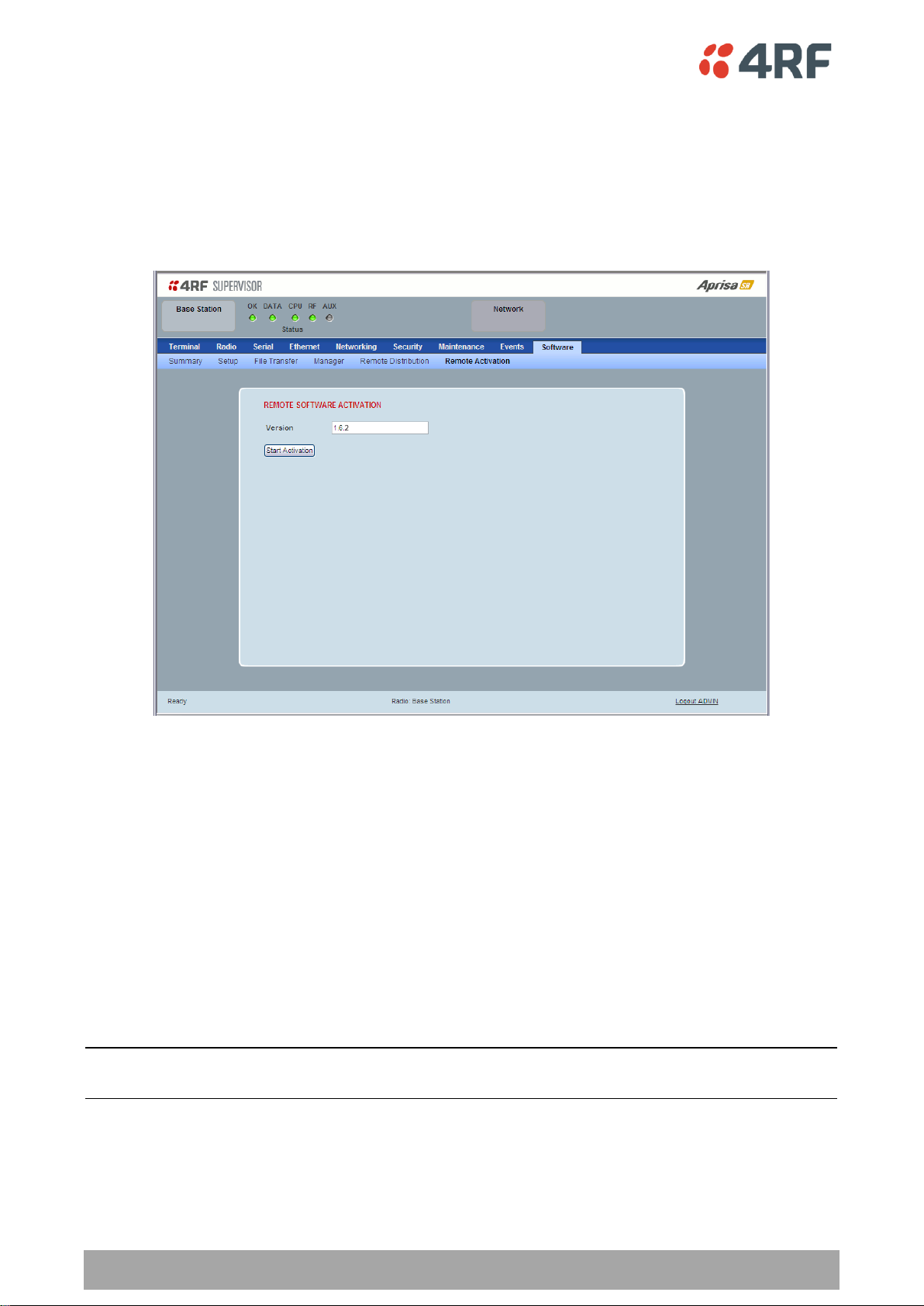
164 | Managing the Radio
Aprisa SR User Manual
Software > Remote Activation
This page provides the mechanism to activate software on all remote stations.
The Software Pack was loaded into the base station with the file transfer process (see ‘Software > File
Transfer’ on page 156) and was distributed via the radio link to all remote stations.
This page is used to manage the activation of that software pack on all remote radios on the network.
This page is only available when the radio is configured as a Base Station.
REMOTE SOFTWARE ACTIVATION
When the software pack version has been distributed to all the remote stations, the software is then
activated in all the remote stations with this command. If successful, then activate the software pack in
the base station to complete the network upgrade.
Version
This parameter displays the software version for activation. The default version is the software pack
version but any valid software version can be entered in the format ‘n.n.n’.
To activate software in remote stations:
This process assumes that a Software Pack has been loaded into the base station with the file transfer
process (see ‘Software > File Transfer’ on page 156) and distributed to all remote radios in the network.
Note: Do not navigate SuperVisor away from this page during the activation process (SuperVisor can lose
PC focus).

Managing the Radio | 165
Aprisa SR User Manual
Result
Function (X of Y)
Remote Radios Polled for
Partners
X is the number of radios polled to determine the number of
protected stations in the network.
Y is the number of remote radios registered with the base station.
Remote Radios Polled for
New Version
X is the number of radios polled to determine the number of radios
that contain the new software version.
Y is the number of remote radios registered with the base station.
Remote Radios Activated
X is the number of radios that contain the new software version
and have been activated.
Y is the number of radios that contain the new software version
and can be activated.
Remote Radios On New
Version
X is the number of radios that has been successfully activated and
now running the new version of software.
Y is the number of radios that the activation command was
executed on.
1. Enter the Software Pack version (if different from displayed version).
2. Click on ‘Start Activation’.
The remote stations will be polled to determine which radios require activation:
When the activation is ready to start:
3. Click on ‘OK’ to start the activation process or Cancel to quit.

166 | Managing the Radio
Aprisa SR User Manual
The page will display the progress of the activation.
The example shows that during the activation process there were exceptions that may need to be
investigated.
When all the remote radios have been activated, the base station radio must now be activated with (see
‘Software > Manager’ on page 159).
4. Click on ‘OK’ to start the activation on the base station.

Managing the Radio | 167
Aprisa SR User Manual
Network Status
Network Status > Network Table
This page displays a list of all the registered remote stations for the base station and provides
management access to each of the remote stations.
NETWORK TABLE
This Network Table is only available when the local radio is the base station i.e. SuperVisor is logged into
the base station.
To manage a remote / repeater station with SuperVisor:
Click on the radio button of the required station. The remaining menu items then apply to the selected
remote station.

168 | Managing the Radio
Aprisa SR User Manual
Result
Function
Network Polling Cycle
The number of poll cycles since first opening a Network Status >
Summary, Exceptions or View page.
The page example shows 6 polling cycles.
Remote Radios Polled
This shows the number of radios polled for the current polling
cycle out of the number remote radios registered with the base
station.
The page example shows 1 radio polled for the current polling
cycle out of 3 remote radios registered.
Polling Interval
The time interval between the completion of one radio poll and
the start of the next radio poll. To set the polling interval, see
‘Maintenance > General’ on page 134.
Network Status > Summary
Network View is an overview of the health of the network providing the ability to investigate issues
directly within SuperVisor.
This page provides an overall summary view of the alarm status of all registered remote stations for the
base station. When open, it provides a continuous monitor of the network.
NETWORK SUMMARY
A network poll will start when any of the Network Status pages are opened (Summary, Exceptions or
View). The network poll will only continue to poll the remote stations if one of the Network Status pages
is open (SuperVisor can lose PC focus). The network poll continues from where it was stopped last time it
was polling.
The initial result assumes that all remote stations are operating correctly.
Network Summary Example:

Managing the Radio | 169
Aprisa SR User Manual
If a remote radio does not respond to a poll request within 10 seconds, the previous readings from that
radio will be presented. Connectivity to a remote radio will be show as ‘lost’ if the remote radio has not
responded to 3 consecutive poll requests.

170 | Managing the Radio
Aprisa SR User Manual
Result
Function
Network Polling Cycle
The number of poll cycles since first opening a Network Status >
Summary, Exceptions or View page.
The page example shows 4 polling cycles.
Remote Radios Polled
This shows the number of radios polled for the current polling
cycle out of the number remote radios registered with the base
station.
The page example shows 3 radios polled for the current polling
cycle out of 4 remote radios registered.
Polling Interval
The time interval between the completion of one radio poll and
the start of the next radio poll. To set the polling interval, see
‘Maintenance > General’ on page 134.
Network Status > Exceptions
This page provides a list of all registered remote radios that are in an alarmed state or have stopped
responding to the SuperVisor polling. When open, it provides a continuous monitor of the network.
NETWORK EXCEPTIONS
A network poll will start when any of the Network Status pages are opened (Summary, Exceptions or
View). The network poll will only continue to poll the remote stations if one of the Network Status pages
is open (SuperVisor can lose PC focus). The network poll continues from where it was stopped last time it
was polling.
Network Exceptions Example:

Managing the Radio | 171
Aprisa SR User Manual
If a remote radio does not respond to a poll request within 10 seconds, the previous readings from that
radio will be presented. Connectivity to a remote radio will be show as ‘lost’ if the remote radio has not
responded to 3 consecutive poll requests.
If a remote radio on the list is detected to be responding to a poll request and no longer be in an alarmed
state, the entry for this remote radio will be removed from the list.
View Events
Clicking on View Events navigates to the Events page (see ‘Events’ on page 144) for the specific remote
radio where the radio events will be displayed.
View Parameters
Clicking on View Parameters navigates to Terminal > Parameters page (see ‘Terminal > Parameters’ on
page 87) for the specific remote radio where the radio parameters will be displayed.

172 | Managing the Radio
Aprisa SR User Manual
Result
Function
Network Polling Cycle
The number of poll cycles since first opening a Network Status >
Summary, Exceptions or View page.
The page example shows 2 polling cycles.
Remote Radios Polled
This shows the number of radios polled for the current polling
cycle out of the number remote radios registered with the base
station.
The page example shows 1 radio polled for the current polling
cycle out of 3 remote radios registered.
Polling Interval
The time interval between the completion of one radio poll and
the start of the next radio poll. To set the polling interval, see
‘Maintenance > General’ on page 134.
Note: as this polling feature utilizes air time, the polling interval
should be selected to suit the network traffic.
Network Status > View
This page provides a complete list of all registered remote radios. It is similar to the Exceptions page but
it shows all radios, not limited to the radios with alarms. When open, it provides a continuous monitor of
the network.
NETWORK VIEW
A network poll will start when any of the Network Status pages are opened (Summary, Exceptions or
View). The network poll will only continue to poll the remote stations if one of the Network Status pages
is open (SuperVisor can lose PC focus). The network poll continues from where it was stopped last time it
was polling.
Network View Example:

Managing the Radio | 173
Aprisa SR User Manual
If a remote radio does not respond to a poll request within 10 seconds, the previous readings from that
radio will be presented. Connectivity to a remote radio will be show as ‘lost’ if the remote radio has not
responded to 3 consecutive poll requests.
View Events
Clicking on View Events navigates to the Events page (see ‘Events’ on page 144) for the specific remote
radio where the radio events will be displayed.
View Parameters
Clicking on View Parameters navigates to Terminal > Parameters page (see ‘Terminal > Parameters’ on
page 87) for the specific remote radio where the radio parameters will be displayed.

174 | Managing the Radio
Aprisa SR User Manual
Protected Station
The majority of SuperVisor screens are the same for the standard radio and the protected station. The
following screens are specific to the protected station.
Parameter Errors
On protected station screens, parameter values displayed in red indicate discrepancies in common
parameter values between the primary and secondary radios (see ‘Protected Station: Terminal >
Summary’ on page 175 for an example of the red display). The value displayed is from the ‘addressed
radio’.
These value discrepancies can occur if the two protected station radios have been separately configured.
The discrepancies can be corrected by re-entering the values in one of the radios. The value will be
copied to the partner radio.

Managing the Radio | 175
Aprisa SR User Manual
Option
Function
Serial Data Driven Switching
Provides radio and RS-232 serial port user interface protection for
Aprisa SR radios.
Redundant
(Protected Station)
The RF ports and interface ports from two standard Aprisa SR
Radios are switched to the standby radio if there is a failure in the
active radio
Terminal
Protected Station: Terminal > Summary
TERMINAL SUMMARY
This page displays the current settings for the Terminal parameters.
PROTECTION INFORMATION
Protection Type
This parameter shows the type of protection:
Active Unit
This parameter shows the radio which is currently active (Primary or Secondary).

176 | Managing the Radio
Aprisa SR User Manual
Switch Count
This parameter shows the number of protection switch-overs since the last radio reboot (volatile).
Primary Address
This parameter shows the IP address of the primary radio (usually the left side radio A).
Secondary Address
This parameter shows the IP address of the secondary radio (usually the right side radio B).
OPERATING SUMMARY
See ‘Terminal > Summary’ on page 78 for parameter details.

Managing the Radio | 177
Aprisa SR User Manual
Protected Station: Terminal > Details
PRIMARY UNIT / SECONDARY UNIT MANUFACTURING DETAILS
See ‘Terminal > Details’ on page 80 for parameter settings.

178 | Managing the Radio
Aprisa SR User Manual
Option
Function
None
The SR radio is stand alone radio (not part of an Aprisa SR
Protected Station).
Redundant
(Protected Station)
The SR radio is part of an Aprisa SR Protected Station.
The RF ports and interface ports from two standard Aprisa SR
Radios are switched to the standby radio if there is a failure in the
active radio
Serial Data Driven Switching
The SR radio is part of an Aprisa SR Data Driven Protected Station.
Provides radio and RS-232 serial port user interface protection for
Aprisa SR radios.
Protected Station: Terminal > Operating Mode
TERMINAL MODE
Operating Mode
The Operating Mode can be set to base station, repeater station or remote station. The default setting is
remote station.
TERMINAL PROTECTION
Protection Type
The Protection Type defines if a radio is a stand-alone radio or part of an Aprisa SR Protected Station. The
default setting is None.

Managing the Radio | 179
Aprisa SR User Manual
PROTECTION MANAGEMENT IP ADDRESS
Primary Address
This parameter shows the IP address of the primary radio (usually the left side radio A).
Secondary Address
This parameter shows the IP address of the secondary radio (usually the right side radio B).
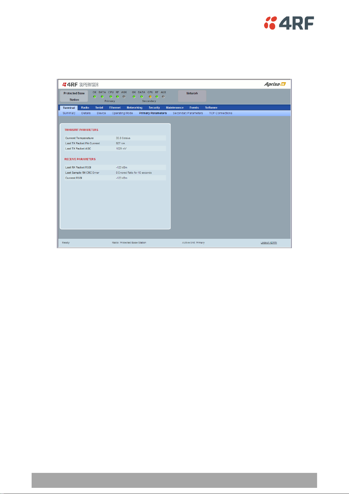
180 | Managing the Radio
Aprisa SR User Manual
Protected Station: Terminal > Primary Parameters
The Parameters page is a dynamic page that will display the parameters associated with the active
alarms, set on ‘Events > Events Setup’ on page 146. The screenshot below shows a small amount of
monitored alarms as an example.
TRANSMIT / RECEIVE PARAMETERS
This parameter displays the parameters of the Primary radio.
See ‘Terminal > Parameters’ on page 87 for parameter details.

Managing the Radio | 181
Aprisa SR User Manual
Protected Station: Terminal > Secondary Parameters
The Parameters page is a dynamic page that will display the parameters associated with the active
alarms, set on ‘Events > Events Setup’ on page 146. The screenshot below shows a small amount of
monitored alarms as an example.
TRANSMIT / RECEIVE PARAMETERS
This parameter displays the parameters of the Secondary radio.
See ‘Terminal > Parameters’ on page 87 for parameter details.

182 | Managing the Radio
Aprisa SR User Manual
Protected Station: Terminal > TCP Connections
The TCP Connections page displays the list of active TCP connections on the radio.
PRIMARY / SECONDARY TCP CONNECTIONS TABLE
The Next button will display the next page of 8 connections and the Prev button will display the previous
page of 8 connections.
If the Auto Refresh option is ticked, the TCP Connections table will refresh every 12 seconds.

Managing the Radio | 183
Aprisa SR User Manual
Protected Station: Ethernet > Summary
This page displays the current settings for the Protected Station Ethernet port parameters.
See ‘Protected Station: Ethernet > Port Setup’ for configuration options.

184 | Managing the Radio
Aprisa SR User Manual
Option
Function
Standard
Enables Ethernet data communication over the radio link.
Switch
Ethernet traffic is switched locally between the two
Ethernet ports and communicated over the radio link
Disabled
Disables Ethernet data communication over the radio link.
Option
Function
Auto
Provides auto selection of Ethernet Port Speed
10
The Ethernet Port Speed is manualy set to 10 Mbit/s
100
The Ethernet Port Speed is manualy set to 100 Mbit/s
Protected Station: Ethernet > Port Setup
This page provides the setup for the Protected Station Ethernet ports settings.
ETHERNET PORT SETTINGS
Mode
This parameter controls the Ethernet traffic flow. The default setting is Standard.
Speed (Mbit/s)
This parameter controls the traffic rate of the Ethernet port. The default setting is Auto.

Managing the Radio | 185
Aprisa SR User Manual
Option
Function
Auto
Provides auto selection of Ethernet Port duplex setting.
Half Duplex
The Ethernet Port is manualy set to Half Duplex.
Full Duplex
The Ethernet Port is manualy set to Full Duplex.
Option
Function
Management Only
The Ethernet port is only used for management of the
network.
Management and User
The Ethernet port is used for management of the network
and User traffic over the radio link.
User Only
The Ethernet port is only used for User traffic over the radio
link.
Duplex
This parameter controls the transmission mode of the Ethernet port. The default setting is Auto.
Function
This parameter controls the use for the Ethernet port. The default setting is Management and User.

186 | Managing the Radio
Aprisa SR User Manual
Protected Station: Networking > IP Summary
This page displays the current settings for the Protected Station Networking IP settings.

Managing the Radio | 187
Aprisa SR User Manual
Protected Station: Networking > IP Setup
This page provides the setup for the Protected Station Networking IP setup.
NETWORKING IP SETTINGS
Changes in these parameters are automatically changed in the partner radio.
Primary IP Address
Set the static IP Address of the primary radio assigned by your site network administrator using the
standard format xxx.xxx.xxx.xxx. The default IP address is in the range 169.254.50.10.
Secondary IP Address
Set the static IP Address of the secondary radio assigned by your site network administrator using the
standard format xxx.xxx.xxx.xxx. The default IP address is in the range 169.254.50.10.
Subnet Mask
Set the Subnet Mask of the radio using the standard format xxx.xxx.xxx.xxx. The default subnet mask is
255.255.0.0.
Gateway
Set the Gateway address of the radio, if required, using the standard format xxx.xxx.xxx. The default
Gateway is 0.0.0.0.

188 | Managing the Radio
Aprisa SR User Manual
Protected Station: Security > Manager
This page provides the management and control of the Protected Station Networking Security settings.
PRIMARY / SECONDARY SECURITY PROFILE
See ‘Security > Manager’ on page 126 for parameter details.

Managing the Radio | 189
Aprisa SR User Manual
Protected Station: Maintenance > General
This page provides the management and control of the Protected Station Maintenance General settings.
See ‘Maintenance > General’ on page 134 for parameter details.

190 | Managing the Radio
Aprisa SR User Manual
Option
Function
Automatic
The protection is automatic and switching will be governed by
normal switching and blocking criteria.
Primary
The primary radio will become active i.e. traffic will be switched
to the primary radio.
Secondary
The secondary radio will become active i.e. traffic will be switched
to the secondary radio.
Maintenance
Protected Station: Maintenance > Protection
This page provides the management and control of the Protected Station Maintenance Protection settings.
SOFTWARE MANUAL LOCK
The software Manual Lock is a software implementation of the Hardware Manual Lock switch on the
Protection Switch.
Lock Active To
This parameter sets the Protection Switch Software Manual Lock. The Software Manual Lock only operates
if the Hardware Manual Lock is deactivated (set to the Auto position).

Managing the Radio | 191
Aprisa SR User Manual
Option
Function
Automatic
The protection is automatic and switching will be governed by
normal switching and blocking criteria.
Software Manual Lock
The Software Manual Lock has control of the protection switch.
Hardware Manual Lock
The Hardware Manual Lock has control of the protection switch.
CURRENT PROTECTION INFORMATION
Switch Control
This parameter shows the status of the switch control i.e. which mechanism is in control of the protection
switch.
Active Unit
This parameter shows the radio which is currently active (Primary or Secondary).
Switch Count
This parameter shows the number of protection switch-overs since the last radio reboot (volatile).

192 | Managing the Radio
Aprisa SR User Manual
Protected Station: Maintenance > Licence
This page provides the management and control of the Protected Station Maintenance Licence settings.
PRIMARY / SECONDARY LICENCE
See ‘Maintenance > Licence’ on page 140 for parameter details.

Managing the Radio | 193
Aprisa SR User Manual
Protected Station: Maintenance > Advanced
This page provides the management and control of the Protected Station Maintenance Advanced settings.
NETWORK
See ‘Maintenance > Advanced’ on page 141 for parameter details.
PRIMARY / SECONDARY CONFIGURATION
See ‘Maintenance > Advanced’ on page 141 for parameter details.

194 | Managing the Radio
Aprisa SR User Manual
Events
The Events menu contains the setup and management of the alarms, alarm events and traps.
Protected Station: Events > Alarm Summary
There are two types of events that can be generated on the Aprisa SR radio. These are:
1. Alarm Events
Alarm Events are generated to indicate a problem on the radio.
2. Informational Events
Informational Events are generated to provide information on key activities that are occurring on the
radio. These events do not indicate an alarm on the radio and are used to provide information only.
See ‘Alarm Types and Sources’ on page 228 for a complete list of events.
PRIMARY / SECONDARY ALARM SUMMARY
See ‘Events > Alarm Summary’ on page 144 for parameter details.

Managing the Radio | 195
Aprisa SR User Manual
Protected Station: Events > Primary History
PRIMARY EVENT HISTORY
See ‘Events > Event History’ on page 145 for parameter details.
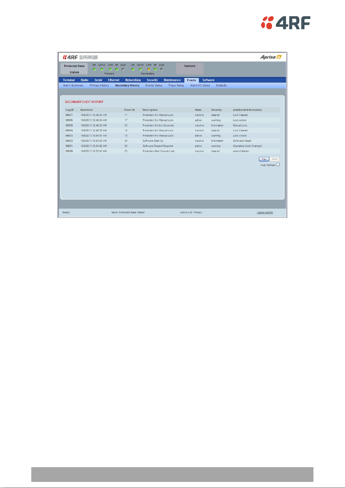
196 | Managing the Radio
Aprisa SR User Manual
Protected Station: Events > Secondary History
SECONDARY EVENT HISTORY
See ‘Events > Event History’ on page 145 for parameter details.

Managing the Radio | 197
Aprisa SR User Manual
Software
The Software menu contains the setup and management of the system software including network
software distribution and activation on a protected station.
Single Radio Software Upgrade
The radio software can be upgraded on a single radio single Aprisa SR radio (see ‘Single Radio Software
Upgrade’ on page 223). This process would only be used if the radio was a replacement or a new station in
an existing network.
Network Software Upgrade
The radio software can be upgraded on an entire Aprisa SR radio network remotely over the radio link (see
‘Network Software Upgrade’ on page 222). This process involves the following steps:
1. Transfer the new software to base station primary radio with ‘Protected Station: Software > Primary
File Transfer’.
2. File Transfer the new software to base station secondary radio with ‘Protected Station: Software >
Secondary File Transfer’.
3. Using the Software Manual Lock, manually lock all protected remotes to the currently active radio
(this is necessary to prevent automatic switching during the distribution and activation process).
4. Distribute the new software to all remote stations with ‘Protected Station: Software > Remote
Distribution’. Note: The software pack in the base station active radio is used for distribution.
5. Activate of the new software on remote stations with ‘Protected Station: Software > Remote
Activation’.
6. Finally, activate the new software on the base station primary and secondary radios. Note: activating
the software will reboot the radio which will reset the Software Manual Lock to Automatic.
 Loading...