


April 2013
Version 1.0.0.03 (for General Availability Release in October 2013)


| 1
Aprisa SR+ Product Description
Copyright
Copyright © 2013 4RF Limited. All rights reserved.
This document is protected by copyright belonging to 4RF Limited and may not be reproduced or
republished in whole or part in any form without the prior written permission of 4RF Limited.
Trademarks
Aprisa and the 4RF logo are trademarks of 4RF Limited.
Windows is a registered trademark of Microsoft Corporation in the United States and other countries. Java
and all Java-related trademarks are trademarks or registered trademarks of Sun Microsystems, Inc. in the
United States and other countries. All other marks are the property of their respective owners.
Disclaimer
Although every precaution has been taken preparing this information, 4RF Limited assumes no liability for
errors and omissions, or any damages resulting from use of this information. This document or the
equipment may change, without notice, in the interests of improving the product.
RoHS and WEEE compliance
The Aprisa SR+ is fully compliant with the European Commission’s RoHS (Restriction of Certain Hazardous
Substances in Electrical and Electronic Equipment) and WEEE (Waste Electrical and Electronic Equipment)
environmental directives.
Restriction of hazardous substances (RoHS)
The RoHS Directive prohibits the sale in the European Union of electronic equipment containing these
hazardous substances: lead, cadmium, mercury, hexavalent chromium, polybrominated biphenyls (PBBs),
and polybrominated diphenyl ethers (PBDEs).
4RF has worked with its component suppliers to ensure compliance with the RoHS Directive which came
into effect on the 1st July 2006.
End-of-life recycling programme (WEEE)
The WEEE Directive concerns the recovery, reuse, and recycling of electronic and electrical equipment.
Under the Directive, used equipment must be marked, collected separately, and disposed of properly.
4RF has instigated a programme to manage the reuse, recycling, and recovery of waste in an
environmentally safe manner using processes that comply with the WEEE Directive (EU Waste Electrical
and Electronic Equipment 2002/96/EC).
4RF invites questions from customers and partners on its environmental programmes and compliance with
the European Commission’s Directives (sales@4RF.com).

2 |
Aprisa SR+ Product Description
Compliance General
The Aprisa SR+ radio predominantly operates within frequency bands that require a site license be issued
by the radio regulatory authority with jurisdiction over the territory in which the equipment is being
operated.
It is the responsibility of the user, before operating the equipment, to ensure that where required the
appropriate license has been granted and all conditions attendant to that license have been met.
Changes or modifications not approved by the party responsible for compliance could void the user’s
authority to operate the equipment.
Equipment authorizations sought by 4RF are based on the Aprisa SR+ radio equipment being installed at a
fixed location and operated in point-to-multipoint or point-to-point mode within the environmental profile
defined by EN 300 019, Class 3.4. Operation outside these criteria may invalidate the authorizations and /
or license conditions.
The term ‘Radio’ with reference to the Aprisa SR+ User Manual, is a generic term for one end station of a
point-to-multipoint Aprisa SR+ network and does not confer any rights to connect to any public network or
to operate the equipment within any territory.
Compliance European Telecommunications Standards Institute
ETSI compliance pending for the Aprisa SR+.
Compliance Federal Communications Commission
FCC compliance pending for the Aprisa SR+.
Compliance Industry Canada
IC compliance pending for the Aprisa SR+.

| 3
Aprisa SR+ Product Description
WARNING:
The installer and / or user of Aprisa SR+ radios shall ensure that a separation distance
as given in the following table is maintained between the main axis of the terminal’s
antenna and the body of the user or nearby persons.
Minimum separation distances given are based on the maximum values of the
following methodologies:
1. Maximum Permissible Exposure non-occupational limit (B or general public) of
47 CFR 1.1310 and the methodology of FCC’s OST/OET Bulletin number 65.
2. Reference levels as given in Annex III, European Directive on the limitation of
exposure of the general public to electromagnetic fields (0 Hz to 300 GHz)
(1999/519/EC). These distances will ensure indirect compliance with the
requirements of EN 50385:2002.
Frequency (MHz)
Maximum Power
(dBm)
Maximum Antenna
Gain (dBi)
Minimum Separation
Distance
(m)
300
+ 37
15
2.5
330
+ 37
15
2.5
400
+ 37
15
2.5
470
+ 37
15
2.3
520
+ 37
15
2.2
850
+ 37
28
7.7
960
+ 37
28
7.2
RF Exposure Warning


Contents | 5
Aprisa SR+ Product Description
Contents
1. Introduction ................................................................................ 9
The 4RF Aprisa SR+ Radio ....................................................................... 9
Product Overview ............................................................................... 10
Network Coverage and Capacity ....................................................... 10
Automatic Registration .................................................................. 10
Remote Messaging ........................................................................ 10
Product Features ......................................................................... 11
Functions .................................................................................. 11
Performance .............................................................................. 11
Usability ................................................................................... 11
Architecture...................................................................................... 12
Security ........................................................................................... 12
Interfaces ......................................................................................... 13
Antenna Interface ........................................................................ 13
Ethernet Interface ....................................................................... 13
RS-232 Interface .......................................................................... 13
USB Interfaces ............................................................................ 13
Alarm Interface ........................................................................... 13
AUX Interface ............................................................................. 13
Mounting .......................................................................................... 14
DIN Rail Mounting ........................................................................ 14
Rack Shelf Mounting ..................................................................... 16
Wall Mounting ............................................................................. 16
2. Product Options ......................................................................... 17
Interface Ports ................................................................................... 17
Protected Station ............................................................................... 18
Operation .................................................................................. 18
Switch Over ........................................................................ 19
Configuration Management ...................................................... 19
Data Driven Protected Station................................................................. 20
Operation .................................................................................. 20

6 | Contents
Aprisa SR+ Product Description
3. Specifications ............................................................................ 21
RF Specifications ................................................................................ 21
ETSI Compliant ............................................................................ 21
Frequency Bands .................................................................. 21
Channel Sizes ...................................................................... 21
Transmitter ......................................................................... 22
Receiver ............................................................................ 24
Modem .............................................................................. 24
Data Payload Security ............................................................ 24
Interface Specifications ........................................................................ 25
Ethernet Interface ....................................................................... 25
RS-232 Asynchronous Interface ......................................................... 25
Protection Switch Specifications ....................................................... 26
Power Specifications ............................................................................ 27
Power Supply .............................................................................. 27
Power Consumption ...................................................................... 27
Power Dissipation ........................................................................ 28
General Specifications .......................................................................... 29
Environmental ............................................................................ 29
Mechanical ................................................................................ 29
Compliance ................................................................................ 29
4. Management ............................................................................. 31
SuperVisor ........................................................................................ 31
Viewing the Aprisa SR+ Terminal Settings ............................................ 32
Configuring the Aprisa SR+ Terminal Details ......................................... 33
Configuring the Aprisa SR+ RF Network Details ...................................... 33
Configuring the Aprisa SR+ Radio Settings ............................................ 34
Command Line Interface ....................................................................... 35
SNMP .............................................................................................. 35
LED Display Panel ............................................................................... 36
Normal Operation ........................................................................ 36
Single Radio Software Upgrade ......................................................... 37
Network Software Upgrade ............................................................. 37
Test Mode ................................................................................. 37
5. Applications .............................................................................. 38
Basic point-to-multipoint application ........................................................ 38
Advanced point-to-multipoint application with repeater ................................. 39
Multi-interface point-to-multipoint application ............................................ 40
6. Architecture ............................................................................. 41
Product Description ............................................................................. 41
Physical Layer ............................................................................. 41
Data Link Layer / MAC layer ............................................................ 41
Channel Access .................................................................... 41
Hop by Hop Transmission ......................................................... 42
Network Layer ............................................................................ 43
Packet Routing ..................................................................... 43
Security ........................................................................................... 44
Product Architecture .................................................................... 45
Aprisa SR+ Block Diagram ............................................................... 46

Contents | vii
7. Contact Us ................................................................................ 47


Introduction | 9
Aprisa SR+ Product Description
1. Introduction
The 4RF Aprisa SR+ Radio
The 4RF Aprisa SR+ is a point-to-multipoint digital radio providing secure narrowband wireless data
connectivity for SCADA, infrastructure and telemetry applications.
The radios carry a combination of serial packet data and Ethernet data between the base station,
repeater stations and remote stations.
The Aprisa SR+ is configurable as a point-to-multipoint base station, a remote station or a repeater
station.

10 | Introduction
Aprisa SR+ Product Description
Product Overview
Network Coverage and Capacity
In a simple point-to-multipoint network, an Aprisa SR+ base station can communicate with up to a
practical limit of 150 remote stations.
The Aprisa SR+ has a typical link range of up to 60 km, however, geographic features, such as hills,
mountains, trees and foliage, or other path obstructions, such as buildings, tend to limit radio coverage.
Additionally, geography may reduce network capacity at the edge of the network where errors may occur
and require retransmission. However, the Aprisa SR+ uses Forward Error Correction (FEC) which greatly
improves the sensitivity performance of the radio resulting in less retries and minimal reduction in
capacity.
Ultimately, the overall performance of any specific network will be defined by a range of factors including
the geographic location, the number of remote stations in the base station coverage area and the traffic
profile across the network. Effective network design will distribute the total number of remote stations
across the available base stations to ensure optimal geographic coverage and network capacity.
Automatic Registration
On start-up, the remote station transmits a registration message to the base stations which responds with
a registration response. This allows the base station to record the details of all the remote stations active
in the network.
If a remote station cannot register with the base station after multiple attempts (RF LED flashing red)
within 10 minutes, it will automatically reboot. If a remote station has registered with the base station
but then loses communication, it will automatically reboot within 2 minutes.
Remote Messaging
There are two message types in the Aprisa SR+ network, broadcast messages and unicast messages.
Broadcast messages are transmitted by the base station to the remote stations and unicast messages are
transmitted by the remote station to the base station. These messages are commonly referred to as uplink
(unicast remote to base) and downlink (broadcast base to remote).
All remotes within the coverage area will receive broadcast messages and pass them on to either the
Ethernet or serial interface. The RTU determines if the message is intended for it and will accept it or
discard it.

Introduction | 11
Aprisa SR+ Product Description
Product Features
Functions
Point-to-Point (PTP) or Point-to-Multipoint (PMP) operation
Licensed frequency bands:
UHF 330-400 MHz
UHF 400-470 MHz
UHF 928-960 MHz
Channel sizes – software selectable:
12.5 kHz
25 kHz
Adaptive modulation: QPSK to 64 QAM
Half duplex or full duplex RF operation
Ethernet data interface and RS-232 asynchronous multiple port options
Software selectable dual / single antenna port options (dual antenna port for external duplexers or
filters)
Data encryption and authentication
Terminal Server
Build-configuration / flexbility of interface ports (3+1, 2+2, 4+0)
Radio and user interface redundancy (provided with Aprisa SR+ Protected Station)
Protected Station fully hot swappable and monitored hot standby
Complies with international standards, including ETSI RF, EMC, safety and environmental standards
Performance
Typical deployment of 30 remote stations from one base station with a practical limit of a few
hundred remote stations
Long distance operation
High transmit power
Low noise receiver
Forward Error Correction
Electronic tuning over the frequency band
Thermal management for high power over a wide temperature range
Usability
Configuration / diagnostics via front panel Management Port USB interface, Ethernet interface
Built-in webserver with full configuration, diagnostics and monitoring functionality, including
remote station configuration / diagnostics over the radio link
LED display for on-site diagnostics
Dedicated alarm port
Software upgrade and diagnostic reporting via the Host Port USB flash drive
Over-the-air software distribution and upgrades
Simple installation with integrated mounting holes for wall, DIN rail and rack shelf mounting

12 | Introduction
Aprisa SR+ Product Description
Architecture
The Aprisa SR+ Architecture is based around a layered TCP/IP protocol stack:
Physical
Proprietary wireless
Standard RS-232 and Ethernet
Link
Proprietary wireless (channel access, ARQ, segmentation)
Standard Ethernet
Network
Standard IP
Proprietary automatic radio routing table population algorithm
Transport
Standard TCP, UDP
Application
Proprietary management application software
Security
The Aprisa SR+ provides security features to implement the key recommendations for industrial control
systems. The security provided builds upon the best in class from multiple standards bodies, including:
IEC/TR 62443 (TC65) ‘Industrial Communications Networks – Network and System Security’
IEC/TS 62351 (TC57) ‘Power System Control and Associated Communications – Data and
Communication Security’
The security features implemented are:
Data encryption
Counter Mode Encryption (CTR) using Advanced Encryption Standard (AES)
Data authentication
Cipher Block Chaining Message Authentication Code (CBC-MAC) using Advanced Encryption
Standard (AES)
Data payload security
CCM Counter with CBC-MAC integrity (NIST special publication 800-38C)
Secured management interface protects configuration
Address filtering enables traffic source authorization
Proprietary physical layer protocol and modified MAC layer protocol based on standardized IEEE
802.15.4
Licensed radio spectrum protects against interference

Introduction | 13
Aprisa SR+ Product Description
Interfaces
Antenna Interface
2 x TNC, 50 ohm, female connectors
Software selectable single or dual antenna port operation.
Ethernet Interface
2, 3 or 4 ports 10/100 base-T Ethernet layer 2 switch using RJ-45
Used for Ethernet user traffic and product management.
RS-232 Interface
2, 1 or 0 RS-232 asynchronous ports using RJ-45 connector
Used for RS-232 asynchronous user traffic only.
USB Interfaces
1 x Management Port using USB micro type B connector
Used for product configuration with the Command Line Interface (CLI).
1 x Host Port using USB standard type A connector
Used for software upgrade and diagnostic reporting.
Alarm Interface
1x Alarm Port using RJ-45 connector
Used for monitoring and control of protection switches.
AUX Interface
1x Port using a QMA female connector
Reserved for future use.
14 | Introduction
Aprisa SR+ Product Description
Part Number
Part Description
APSA-MBRK-DIN-SQ
4RF SR Acc, Bracket, DIN Rail, Aprisa SR+
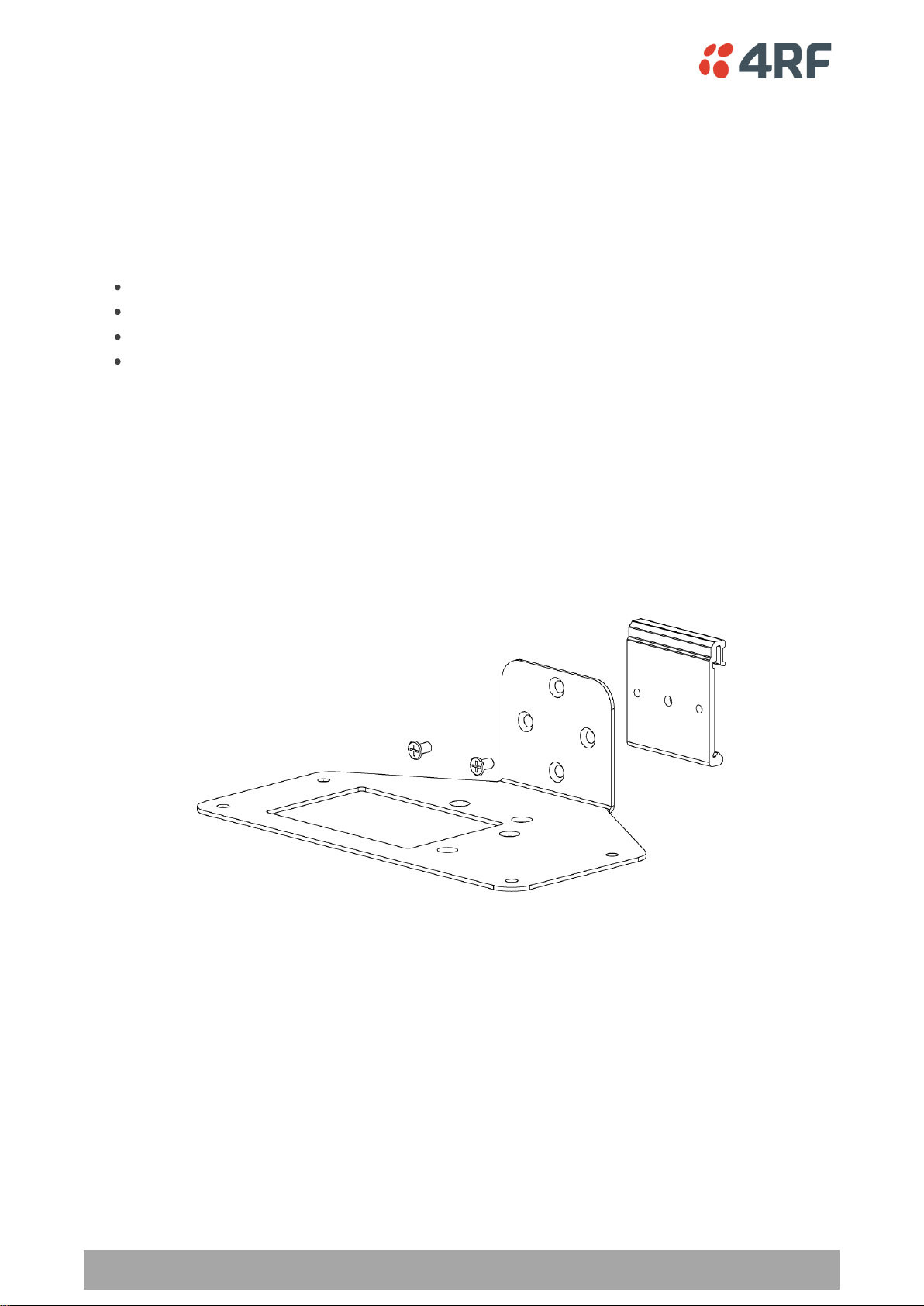
Mounting
The Aprisa SR+ has four threaded holes (M4) in the enclosure base and two holes (5.2 mm) through the
enclosure for mounting.
Mounting options include:
DIN rail mounting with the Aprisa SR+ DIN Rail Mounting Bracket
Rack shelf mounting
Wall mounting
Outdoor enclosure mounting
DIN Rail Mounting
The Aprisa SR+ has an optional accessory to enable the radio to mount on a standard DIN rail:

Introduction | 15
Aprisa SR+ Product Description
The Aprisa SR+ DIN rail mounting bracket can be mounted in four positions on a horizontal DIN rail:
Vertical Mount (vertical enclosure perpendicular to the mount)
Horizontal Mount (horizontal enclosure perpendicular to the mount)
Flat Vertical Mount (vertical enclosure parallel to the mount)
Flat Horizontal Mount (horizontal enclosure parallel to the mount)

16 | Introduction
Aprisa SR+ Product Description
Rack Shelf Mounting
The Aprisa SR+ can be mounted on a rack mount shelf using the four M4 threaded holes in the Aprisa SR+
enclosure base. The following picture shows two Aprisa SR+ radios mounted on 1 RU rack mount shelf.
Wall Mounting
The Aprisa SR+ can be mounted on a wall using the two holes through the enclosure (5.2 mm diameter).
Typically, M5 screws longer than 35 mm would be used.
Product Options | 17
Aprisa SR+ Product Description
Interface Port Option
Part Number
4 Ethernet ports and no RS-232 serial ports
APSQ-N400-SSC-HD-40-ETAA
3 Ethernet ports and 1 RS-232 serial port
APSQ-N400-SSC-HD-31-ETAA
2 Ethernet ports and 2 RS-232 serial ports
APSQ-N400-SSC-HD-22-ETAA
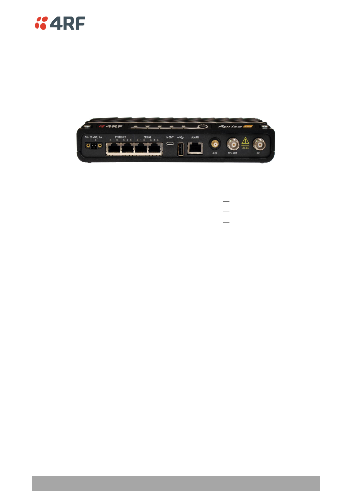
2. Product Options
Interface Ports
The standard Aprisa SR+ provides multiple interface port options for combinations of Ethernet and RS-232
serial. The product shown below is the two Ethernet ports plus two RS-232 serial ports.

18 | Product Options
Aprisa SR+ Product Description
Part Number
Part Description
APSQ-R400-SSC-FD-22-ETAA
4RF SR+, PS, 400-470 MHz, SSC, Full Duplex, 2E2S, ET, AA
Protected Station
The Aprisa SR+ Protected Station provides radio and user interface protection for Aprisa SR+ radios when
configured as a base station. The RF ports and interface ports from two standard Aprisa SR+ radios are
switched to the standby radio if there is a failure in the active radio.
Option Example
The Aprisa SR+ Protected Station is comprised of an Aprisa SR+ Protection Switch and two standard Aprisa
SR+ radios mounted in a 2U rack mounting chassis.
The Aprisa SR+ Protected Station is full monitored hot-standby and fully hot-swappable. All interfaces (RF,
data, etc.) are continually monitored on both the active and standby radio to ensure correct operation.
The standby radio can be replaced without impacting traffic flow on the active radio.
The Aprisa SR+ radios can be any of the currently available Aprisa SR+ radio frequency bands, channel
sizes or interface port options.
By default, the Aprisa SR+ Protected Station is configured with the left hand radio (A) designated as the
primary radio and the right hand radio (B) designated as the secondary radio.
Each radio is configured with its own unique IP and MAC address and the address of the partner radio.
On power-up, the primary radio will assume the active role and the secondary radio will assume the
standby role. If, for some reason, only one radio is powered on it will automatically assume the active
role.
Operation
In normal operation, the active radio carries all RS-232 serial and Ethernet traffic over the radio link and
the standby radio is unused with its transmitter turned off. Both radios are continually monitored for
correct operation and alarms are raised if an event occurs.
The active radio sends regular ‘keep alive’ messages to the standby radio to indicate it is operating
correctly. In the event of a failure on the active radio, the RF link and user interface traffic is
automatically switched to the standby radio.
The failed radio can then be replaced in the field without interrupting user traffic (see Aprisa SR+ User
Manual).

Product Options | 19
Aprisa SR+ Product Description
Switch Over
The switch over to the standby radio can be initiated automatically, on fault detection, or manually via
the Hardware Manual Lock switch on the Protection Switch or the Software Manual Lock from SuperVisor.
Additionally, it is possible to switch over the radios remotely without visiting the station site, via the
remote control connector on the front of the Protection Switch.
Configuration Management
The Primary and Secondary radios are managed with the embedded web-based management tool,
SuperVisor, by using either the Primary or Secondary IP address. Configuration changes in one of the radios
will automatically be reflected in the partner radio.
To ensure all remote stations are registered to the correct (active) base station, changes to the Network
Table are automatically synchronized from the active radio to the standby radio. The Network Table is
only visible on the active radio. This synchronization does not occur if the Hardware Manual Lock is active.

20 | Product Options
Aprisa SR+ Product Description
Part Number
Part Description
APSQ-D400-SSC-FD-22-ETAA
4RF SR+, PD, 400-470 MHz, SSC, Full Duplex, 2E2S, ET, AA
Data Driven Protected Station
The Aprisa SR+ Data Driven Protected Station provides radio and RS-232 serial port user interface
protection for Aprisa SR+ radios when configured as a base station.
Option Example
The Aprisa SR+ Data Driven Protected Station shown is comprised of two standard Aprisa SR+ dual antenna
port option radios and two external duplexers mounted on 19" rack mounting shelves (as shown above).
The Aprisa SR+ radios can be any of the currently available Aprisa SR+ radio frequency bands, channel
sizes or single / dual antenna port options.
By default, the Aprisa SR+ Data Driven Protected Station is configured with the left hand radio (A)
designated as the primary radio and the right hand radio (B) designated as the secondary radio.
Each radio is configured with its own unique IP and MAC address and the address of the partner radio.
On power-up, the primary radio will assume the active role and the secondary radio will assume the
standby role. If, for some reason, only one radio is powered on it will automatically assume the active
role.
Operation
In normal operation, the active radio carries all RS-232 serial and Ethernet traffic over the radio link and
the standby radio is unused with its transmitter turned off. Both radios are continually monitored for
correct operation and alarms are raised if an event occurs.
Both the active and standby radios send regular ‘keep alive’ messages to each other to indicate if they are
operating correctly. In the event of a failure on the active radio, the RF link and user interface traffic is
automatically switched to the standby radio.
The failed radio can then be replaced in the field without interrupting user traffic.

Specifications | 21
Aprisa SR+ Product Description
Broadcast Band
Frequency Band
Frequency Tuning
Range
Synthesizer Step
Size
UHF
300 MHz
330-400 MHz
6.250 kHz
UHF
400 MHz
400-470 MHz
6.250 kHz
UHF
900 MHz
928-960 MHz
6.250 kHz
Channel Size
Gross Radio Capacity
64 QAM
16 QAM
QPSK
4-CPFSK
12.5 kHz
60.0 kbit/s
40.0 kbit/s
20.0 kbit/s
9.6 kbit/s
25 kHz
120.0 kbit/s
80.0 kbit/s
40.0 kbit/s
19.2 kbit/s
3. Specifications
RF Specifications
ETSI Compliant
Frequency Bands
Channel Sizes

22 | Specifications
Aprisa SR+ Product Description
Average Power output
64 QAM
0.01 to 1.25 W (+10 to +34 dBm, in 1 dB steps)
Note: The Peak Envelope Power
(PEP) at maximum set power
level is +41 dBm.
16 QAM
0.01 to 2.5 W (+10 to +35 dBm, in 1 dB steps)
QPSK
0.01 to 5.0 W (+10 to +37 dBm, in 1 dB steps)
4-CPFSK
0.01 to 10.0 W (+10 to +40 dBm, in 1 dB steps)
Preamble Average Power
SuperVisor Setting
QPSK Average Power
SuperVisor Setting
16 QAM Average Power
SuperVisor Setting -2 dBm
64 QAM Average Power
SuperVisor Setting -3 dBm
Peak Power
+41 dBm
Adjacent channel power
< - 60 dBc
Transient adjacent channel power
< - 50 dBc
Spurious emissions
< - 37 dBm
Attack time
< 1.5 ms
Release time
< 1.5 ms
Data turnaround time
< 10 ms
Frequency stability
± 1 ppm
Frequency aging
< 1 ppm / annum
Synthesizer lock time
< 1.5 ms (5 MHz step)
Transmitter
When the transmitter power is set from SuperVisor, it sets the output power of the preamble sent with
every transmit burst. The actual power per modulation will be:
Note: The Aprisa SR+ transmitter contains power amplifier protection which allows the antenna to be
disconnected from the antenna port without product damage.
Note: The demo Aprisa SR+ (model number SQ D400-002) has a maximum transmitter power of 5 W with a
peak power of +37 dBm. It also does not support 4-CPFSK modulation.

Specifications | 23
Aprisa SR+ Product Description
Maintenance > Test Mode
TRANSMITTER
PRBS Test Enabled
When active, the transmitter outputs a continuous PRBS signal. This can be used for evaluating the output
spectrum of the transmitter and verifying adjacent channel power and spurious emission products.
Deviation Test Enabled
When active, the transmitter outputs a sideband tone at the deviation frequency used by the CPFSK
modulator. This can be used to evaluate the local oscillator leakage and sideband rejection performance
of the transmitter.
CW Test Enabled
When active, the transmitter outputs a continuous wave signal. This can be used to verify the frequency
stability of the transmitter.
Test Mode Timeout (s)
This parameter sets the Transmitter Test Mode timeout period. The radio will automatically exit
Transmitter Test Mode after the Timeout period. The default setting is 10 seconds.

24 | Specifications
Aprisa SR+ Product Description
12.5 kHz
25 kHz
Receiver sensitivity
BER < 10-2
4-CPFSK
–115 dBm
–112 dBm
BER < 10-2
QPSK
–115 dBm
–112 dBm
BER < 10-2
16 QAM
–109 dBm
–106 dBm
BER < 10-2
64 QAM
–103 dBm
–99 dBm
BER < 10-6
4-CPFSK
–108 dBm
–105 dBm
BER < 10-6
QPSK
–108 dBm
–105 dBm
BER < 10-6
16 QAM
–102 dBm
–99 dBm
BER < 10-6
64 QAM
–96 dBm
–92 dBm
Adjacent channel selectivity
> 60 dB
> 66 dB
Co-channel rejection max coded QPSK
> –5 dB
Co-channel rejection max coded 64 QAM
> –20 dB
Intermodulation response rejection
> 70 dB
Blocking or desensitization
> 84 dB
Spurious response rejection
> 75 dB
Forward Error Correction
Variable length concatenated Reed Solomon
plus convolutional code
Adaptive Burst Support
Adaptive FEC
Adaptive modulation
Data payload security
CCM* Counter with CBC-MAC
Data encryption
Counter Mode Encryption (CTR) using Advanced
Encryption Standard (AES) 128, 192 or 256
Data authentication
Cipher Block Chaining Message Authentication
Code (CBC-MAC) using Advanced Encryption
Standard (AES) 128, 192 or 256
Receiver
Modem
Data Payload Security

Specifications | 25
Aprisa SR+ Product Description
General
Interface
RJ-45 x 2 (Integrated 2-port switch)
Cabling
CAT-5 UTP, supports auto MDIX (Standard Ethernet)
Maximum line length
100 metres on cat-5 or better
Bandwidth allocation
The Ethernet capacity maximum is determined by the
available radio link capacity.
Maximum transmission unit
Option setting of 1522 or 1536 octets
Address table size
1024 MAC addresses
Ethernet mode
10Base-T or 100Base-TX
Full duplex or half duplex
(Auto-negotiating and auto-sensing)
Diagnostics
Left Green LED
Off: no Ethernet signal received
On: Ethernet signal received
Right Green LED
Off: Indicates no data traffic present on the interface
Flashing: Indicates data traffic present on the interface
General
Interface
ITU-T V.24 / EIA/TIA RS-232E
Interface direction
DCE only
Maximum line length
10 metres
Async
parameters
Standard mode data bits
7 or 8 bits
Standard mode parity
Configurable for None, Even or Odd
Standard mode stop bits
1 or 2 bits
Interface baud rates
300, 1200, 2400, 4800, 9600, 19200, 38400, 57600 and
115200 bit/s
Control signals
DCE to DTE
CTS, RTS, DSR, DTR
Interface Specifications
Ethernet Interface
The Aprisa SR+ radio features an integrated 10Base-T/100Base-TX layer-2 Ethernet switch.
To simplify network setup, each port supports auto-negotiation and auto-sensing MDI/MDIX. Operators can
select from the following preset modes:
Auto negotiate
10Base-T half or full duplex
100Base-TX half or full duplex
The switch is IEEE 802.3-compatible. It passes VLAN tagged traffic.
RS-232 Asynchronous Interface
The Aprisa SR+ radio’s ITU-T V.24 compliant RS-232 interface is configured as a Cisco® pinout DCE. The
interface terminates to a DTE using a straight-through cable or to a DCE with a crossover cable (null
modem).
The interface uses two handshaking control lines between the DTE and the DCE.

26 | Specifications
Aprisa SR+ Product Description
RF Insertion Loss
< 0.5 dB
Remote Control inputs
Logic 4700 ohms pullup to +3.3 VDC
Protection Switch Specifications

Specifications | 27
Aprisa SR+ Product Description
Nominal voltage
+13.8 VDC (negative earth)
Input voltage range
+10 to +30 VDC
Maximum power input
30 W
Connector
Molex 2 pin male screw fitting
39526-4002
Nominal voltage
+13.8 VDC (negative earth)
Input voltage range
+10 to +30 VDC
Maximum power input
35 W
Connector
2x Molex 2 pin male screw fitting
39526-4002
Nominal voltage
+13.8 VDC (negative earth)
Input voltage range
+10 to +30 VDC
Maximum power input
35 W
Connector
2x Molex 2 pin male screw fitting
39526-4002
Mode
Power Consumption
(10 W radio with 4-CPFSK modulation)
Transmit / Receive
< 35 W for 10 W transmit power
< 25.0 W for 1 W transmit power
Receive only
< 6 W full Ethernet traffic activity
< 4.5 W no Ethernet traffic activity
Mode
Power Consumption
(10 W radios with 4-CPFSK modulation)
Transmit / Receive
< 42 W for 10 W transmit power
< 32.0 W for 1 W transmit power
Receive only
< 14.5 W full Ethernet traffic activity
< 11.5 W no Ethernet traffic activity
Power Specifications
Power Supply
Aprisa SR+ Radio
Aprisa SR+ Protected Station
Aprisa SR+ Data Driven Protected Station
Power Consumption
Aprisa SR+ Radio
Aprisa SR+ Protected Station and Aprisa SR+ Data Driven Protected Station

28 | Specifications
Aprisa SR+ Product Description
Transmit Power
Power Dissipation
(10 W radio with 4-CPFSK modulation)
10 W transmit power
< 25 W
1 W transmit power
< 24 W
Transmit Power
Power Dissipation
(10 W radios with 4-CPFSK modulation)
10 W transmit power
< 32 W
1 W transmit power
< 31 W
Power Dissipation
Aprisa SR+ Radio
Aprisa SR+ Protected Station and Aprisa SR+ Data Driven Protected Station

Specifications | 29
Aprisa SR+ Product Description
Operating temperature range
-40 to +70˚ C
Storage temperature range
-40 to +80˚ C
Operating humidity
Maximum 95% non-condensing
Acoustic noise emission
No audible noise emission
Dimensions
Width 210 mm
Depth 130 mm (146 mm with TNC
connectors)
Height 41.5 mm
Weight
1.25 kg
Colour
Matt black
Mounting
Wall (2 x M5 screws)
Rack shelf (2 x M4 screws)
DIN rail bracket
Dimensions
Width 432.6 mm
Depth 372 mm (388 mm with TNC
connectors)
Height 2U plus external duplexer (if used)
Weight
12 kg (includes the 2 radios)
Colour
Matt black
Mounting
Rack mount (2 x M6 screws)
Radio
EN 300 113-2
EMI / EMC
EN 301 489 Parts 1 & 5
Safety
EN 60950-1:2006
Environmental
ETS 300 019 Class 3.4
General Specifications
Environmental
Mechanical
Aprisa SR+ Radio
Aprisa SR+ Protected Station
Compliance


Management | 31
Aprisa SR+ Product Description
4. Management
SuperVisor
The Aprisa SR+ contains an embedded web server application (SuperVisor) to enable element management
with any major web browser (such as Mozilla Firefox, Microsoft® Internet Explorer).
SuperVisor enables operators to configure and manage the Aprisa SR+ base station radio and repeater /
remote station radios over the radio link.
The key features of SuperVisor are:
Full element management, configuration and diagnostics
Manage the entire FAN (Field Area Network) from the Base Station (remote management of
elements)
Managed network software distribution and upgrades
Performance and alarm monitoring of the entire network, including RSSI, alarm states, time-
stamped events, etc.
View and set standard radio configuration parameters including frequencies, transmit power,
channel size, modulation, channel access, serial port settings and Ethernet port settings
Set and view security parameters
User management
The following are three examples of SuperVisor screens:

32 | Management
Aprisa SR+ Product Description
Viewing the Aprisa SR+ Terminal Settings
The SuperVisor software enables operators to view the terminal settings:

Management | 33
Aprisa SR+ Product Description
Network ID (FAN)
(Field Area Network)
– four hex chars
– network ID of this base station node and its remote nodes
Network Radius
– sets the maximum number of hops in this network
Network Repeaters Proximity
– sets the proximity of repeaters in this network
Inband Management
- enables Inband Management of remotes / repeaters
Inband Management Timeout (sec)
- sets the Inband Management timeout period
Configuring the Aprisa SR+ Terminal Details
The SuperVisor software enables operators to set the terminal details including:
Terminal Name
Location
Contact Name
Contact Details
Current Date
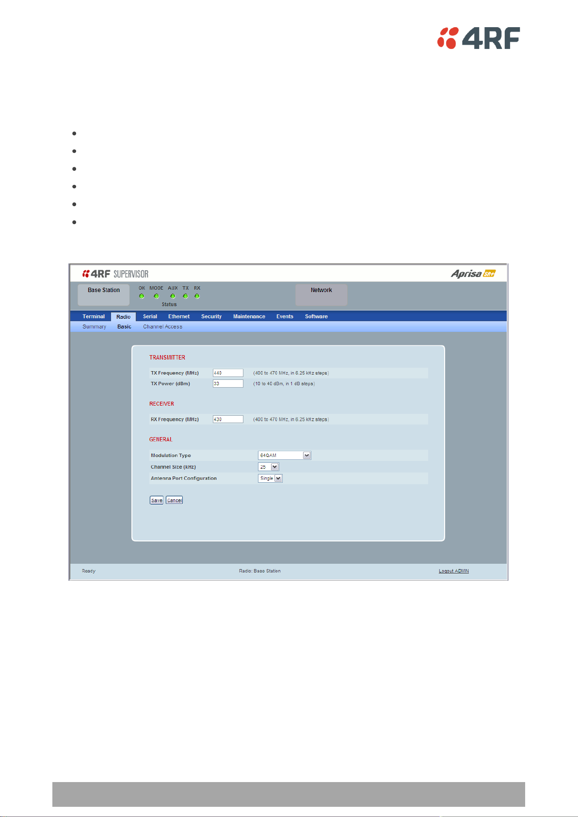
Configuring the Aprisa SR+ RF Network Details
The SuperVisor software enables operators to set the RF Network Details including:
34 | Management
Aprisa SR+ Product Description
TX Frequency
– sets the Transmit frequency in MHz
TX Power
– sets the Transmit Power in dBm
RX Frequency
– sets the Receive frequency in MHz
Modulation Type
- sets the Modulation Type QPSK to 64 QAM
Channel Size
- sets the Channel Size 12.5 kHz or 25 kHz
Antenna Port Configuration
- sets the Antenna Port Configuration to single port or dual
port
Configuring the Aprisa SR+ Radio Settings
The SuperVisor software enables operators to set the radio settings including:

Management | 35
Aprisa SR+ Product Description
Command Line Interface
The Aprisa SR+ has a Command Line Interface (CLI) which provides basic product setup and configuration.
This interface can be accessed via an Ethernet Port (RJ-45) or the Management Port (USB micro type B).
The Terminal menu is shown in the following picture:
SNMP
In addition to web-based management (SuperVisor) and the Command Line Interface, the Aprisa SR
network can also be managed using the Simple Network Management Protocol (SNMP). MIB files are
supplied, and these can be used by a dedicated SNMP Manager, such as Castle Rock’s SNMPc, to access
most of the radio’s configurable parameters.
For communication between the SNMP manager and the radio, Access Controls and Community strings
must be set up as described in the Aprisa SR+ User Manual .

36 | Management
Aprisa SR+ Product Description
OK
MODE
AUX
TX
RX
Solid
Red
Alarm present
with severity
Critical, Major
and Minor
TX path fail
RX path fail
Flashing
Red
Radio not
connected to a
base station
Radio not
connected to a
base station
Solid
Orange
Alarm present
with Warning
Severity
Flashing
Orange
Tx Data or Rx
Data on the
USB
management
or data port
Diagnostics
Function
Active
Flashing
Green
RF path TX is
active
RF path RX is
active
Solid
Green
Power on and
functions OK
and no alarms
USB interface
OK
Processor
Block is OK
Tx path OK
Rx path OK
LED Colour
Severity
Green
No alarm – information only
Orange
Warning alarm
Red
Critical, major or minor alarm
LED Display Panel
The Aprisa SR+ has an LED Display panel which provides on-site alarms / diagnostics without the need for
PC.
Normal Operation
In normal radio operation, the LEDs indicate the following conditions:

Management | 37
Aprisa SR+ Product Description
Single Radio Software Upgrade
During a radio software upgrade, the LEDs indicate the following conditions:
Software upgrade started - the OK LED flashes orange
Software upgrade progress indicated by running RX to OK LEDs
Software upgrade completed successfully - the OK LED solid orange
Software upgrade failed - any LED flashing red during the upgrade
Network Software Upgrade
During a network software upgrade, the AUX LED flashes orange on the base station and all remote
stations.
Test Mode
In Test Mode, the LED Display panel presents a real time visual display of the RSSI. This can be used to
adjust the antenna for optimum signal strength.

38 | Applications
Aprisa SR+ Product Description
5. Applications
This section describes sample Aprisa SR+ radio applications.
The following applications are described:
Basic point-to-multipoint application
Advanced point-to-multipoint application with repeaters
Multi-interface point-to-multipoint application
Basic point-to-multipoint application
Single base station with Ethernet SCADA data inputs to multiple geographically remote sites with Ethernet
RTUs requiring control and data acquisition.
The base station receives Ethernet frames from the SCADA server LAN and broadcasts all Ethernet frames
to all remote stations
Each remote site receives Ethernet frames from the RTU and unicasts over the air to the base station.
The base station uses an omni directional antenna to provide wide coverage and the remote stations are
fitted with directional Yagi antennas to provide higher gain.

Applications | 39
Aprisa SR+ Product Description
Advanced point-to-multipoint application with repeater
Single base station with Ethernet SCADA data inputs to multiple geographically remote sites with Ethernet
RTUs requiring control and data acquisition. A repeater is deployed to service remote sites beyond the
reach of the base station.
The base station receives Ethernet frames from the SCADA server LAN and broadcasts all Ethernet frames
to the repeater and its remote stations.
Three remote sites have direct radio communication with the base station but the other two remote sites
operate via the repeater site.
Each remote site receives Ethernet frames from the RTU and unicasts over the air to the repeater / base
station.
The base station and the repeater station use an omni directional antenna to provide wide coverage and
the remote stations are fitted with directional Yagi antennas to provide higher gain.

40 | Applications
Aprisa SR+ Product Description
Multi-interface point-to-multipoint application
Single base station with Ethernet and RS-232 SCADA data inputs to multiple geographically remote sites
with Ethernet and RS-232 RTUs requiring control and data acquisition.
The base station receives Ethernet / RS-232 frames from the SCADA servers and broadcasts all frames to
all remote stations
Each remote site receives Ethernet / RS-232 frames from the RTU and unicasts over the air to the base
station.
The base station uses an omni directional antenna to provide wide coverage and the remote stations are
fitted with directional Yagi antennas to provide higher gain.

Architecture | 41
Aprisa SR+ Product Description
Access Mode
Function
Access Request
Channel access scheme where the base stations controls the
communication on the channel. Remotes ask for access to the
channel, and the base station grants access if the channel is not
occupied.
Listen Before Send
Channel access scheme where network elements listen to ensure
the channel is clear, before trying to access the channel.
6. Architecture
Product Description
There are three components to the wireless interface: the Physical Layer (PHY), the Data Link Layer (DLL)
and the Network Layer. These three layers are required to transport data across the wireless channel in
the Point-to-Multipoint (PMP) configuration. The Aprisa SR+ DLL is largely based on the 802.15.4 MAC layer
using a proprietary implementation.
Physical Layer
The Aprisa SR+ supports one or two frequency ½ duplex RF operation or full duplex two frequency RF
operation.
The ½ duplex RF operation eliminates the need for an external duplexer.
The full duplex RF operation requires the use of an external duplexer connected to the radio’s dual
antenna ports (TX and RX).
The Aprisa SR+ is a packet based radio. Data is sent over the wireless channel in discrete packets /
frames, separated in time. The PHY demodulates data within these packets with coherent detection.
The Aprisa SR+ PHY provides carrier, symbol and frame synchronisation predominantly through the use of
preambles. This preamble prefixes all packets sent over the wireless channel which enables fast
synchronisation.
Remote nodes are predominantly in receive mode with only sporadic bursts of transmit data. This reduces
power consumption.
Data Link Layer / MAC layer
The Aprisa SR+ PHY enables multiple users to be able to share a single wireless channel; however a DLL is
required to manage data transport. The two key components to the DLL are channel access and hop by
hop transmission.
Channel Access
The Aprisa SR+ radio has two modes of channel access, Access Request and Listen Before Send.

42 | Architecture
Aprisa SR+ Product Description
Access Request
This scheme is particularly suited to digital SCADA systems where all data flows through the base station.
In this case it is important that the base station has contention-free access as it is involved in every
transaction. The channel access scheme assigns the base station as the channel access arbitrator and
therefore inherently it has contention-free access to the channel. This means that there is no possibility
of contention on data originating from the base station. As all data flows to or from the base station, this
significantly improves the robustness of the system.
All data messages are controlled via the AG (access grant) control message and therefore there is no
possibility of contention on the actual end user data. If a remote station accesses the channel, the only
contention risk is on the AR (access request) control message. These control messages are designed to be
as short as possible and therefore the risk of collision of these control messages is significantly reduced.
Should collisions occur these are resolved using a random back off and retry mechanism.
As the base station controls all data transactions multiple applications can be effectively handled,
including a mixture of polling and report by exception.
Listen Before Send
The Listen Before Send channel access scheme is realized using Carrier Sense Multiple Access (CSMA). In
this mode, a pending transmission requires the channel to be clear. This is determined by monitoring the
channel for other signals for a set time prior to transmission. This results in reduced collisions and
improved channel capacity.
There are still possibilities for collisions with this technique e.g. if two radios simultaneously determine
the channel is clear and transmit at the same time. In this case an acknowledged transaction may be used.
The transmitter requests an ACK to ensure that the transmission has been successful. If the transmitter
does not receive an ACK, then random backoffs are used to reschedule the next transmission.
Hop by Hop Transmission
Hop by Hop Transmission is realized in the Aprisa SR+ by adding a MAC address header to the packet. For
802.15.4, there are 2 addresses, the source and destination addresses.

Architecture | 43
Aprisa SR+ Product Description
Network Layer
Packet Routing
Packet routing is realized in the Aprisa SR+ by adding a network address header to the packet. This
contains source and destination addresses. For the Network Layer, there are 2 addresses, the address of
the originating radio and the address of the terminating radio (i.e. end to end network). This is required
for routing packets across multiple hops e.g. PMP with repeaters.
The Aprisa SR+ uses an automated method for performing address assignment and routing information.
There are two types of packets: unicast and broadcast. Only the base station sends broadcasts which are
received by all remote stations. User packets are not interpreted as the radio link is transparent.
Traffic
Data originating on the base station is broadcast to all repeater stations and remote stations
Data originating on a remote station is unicast to the base station only
This can be via multiple repeater stations.
Data originating on a repeater station is unicast to the base station only
Data originating on a base station serial port is terminated on remote station serial ports only
Data originating on a base station Ethernet port is terminated on remote station Ethernet ports or
serial ports (Terminal Server mode)
User Traffic
User traffic is prioritized depending on the Serial and Ethernet Data Priority options.
If the Serial and Ethernet Data Priority options are equal, then first come first served is invoked.
Repeater stations repeat traffic also on a first come first served basis.
Management Traffic
Ethernet Management Traffic is also prioritized relative to user traffic.

44 | Architecture
Aprisa SR+ Product Description
Security
The Aprisa SR+ provides security features to implement the key recommendations for industrial control
systems. The security provided builds upon the best in class from multiple standards bodies, including:
IEC/TR 62443 (TC65) ‘Industrial Communications Networks – Network and System Security’
IEC/TS 62351 (TC57) ‘Power System Control and Associated Communications – Data and
Communication Security’
The security features implemented are:
Data encryption
Counter Mode Encryption (CTR) using Advanced Encryption Standard (AES)
Data authentication
Cipher Block Chaining Message Authentication Code (CBC-MAC) using Advanced Encryption
Standard (AES)
Data payload security
CCM Counter with CBC-MAC integrity (NIST special publication 800-38C)
Secured management interface protects configuration
Address filtering enables traffic source authorization
Proprietary physical layer protocol and modified MAC layer protocol based on standardized IEEE
802.15.4
Licensed radio spectrum protects against interference

Architecture | 45
Aprisa SR+ Product Description
Product Architecture
The following are the key components of the Aprisa SR+ design:
Dual high performance ΣΔ fractional-N synthesizers to allow for full duplex operation
2x output frequency VCO for minimal pulling during transmit
Wideband design electronically tunes over entire band
Proven ultra low noise and spurious technology with over 50dB of SNR easily achieved
Direct quadrature mixer with integrated Cartesian Feedback Loop
The Cartesian Feedback Loop improves the efficiency and linearity of the entire transmitter chain
for non-constant envelope modulation systems
Simple IQ modulation line up reduces part count and improves MTBF
No mixing stages so no spurious responses present at the transmitter output
Digital control loops used for controlling power amplifier current and transmit output power, allows for
faster ramping and settling times with less error
Tx turn-on time limited primarily by PA ramping
Robust, closed-loop power control – fast, accurate power ramp up and down
Uses the latest high ruggedness N-Channel RF Power LDMOS transistors for the power amplifier
High efficiency (>50% PAE at 10W)
Very low thermal resistance (1.0°C/W)
Direct IQ down-conversion
Excellent Intermodulation distortion characteristics as channel filter can be placed directly after
the mixer without impacting noise figure
Digital channel filtering allows for multiple bandwidths with the same hardware
Low parts count and no crystal filters help to keep receiver performance extremely stable over
temperature
Integrated heat sink
Limits number of mechanical interfaces
Fin design optimized for natural convection
Monitoring and software control
Temperature control loop shuts down the transmitter when the temperature exceeds continuous
operation at 70°C
Monitoring of RSSI and PA current to ensure the RF hardware is functioning to specification

46 | Architecture
Aprisa SR+ Product Description
Aprisa SR+ Block Diagram

Contact Us | 47
Aprisa SR+ Product Description
4RF Limited
26 Glover Street, Ngauranga
PO Box 13-506
Wellington 6032
New Zealand
Email address
support@4rf.com
Website
www.4rf.com
Phone number
+64 4 499 6000
Fax number
+64 4 473 4447
Attention
Customer Services
7. Contact Us
For further information or assistance, please contact Customer Support or your local 4RF representative.
Our area representative contact details are available from our website:
 Loading...