How it Works
Log In / Sign Up
Buy Points
How it Works
FAQ
Contact Us
Questions and Suggestions
Users
4RF
Loading...
A
Aprisa LE
Aprisa SR+
12
Aprisa SRi
Aprisa XE
7
E
E1
T
T1
Loading...
Loading...
Nothing found
Aprisa SR+
User Manual
83 pgs
4.22 Mb
0
User Manual
72 pgs
2.98 Mb
0
User Manual
1 pgs
69.26 Kb
0
User Manual
233 pgs
5.58 Mb
0
User Manual
99 pgs
5.07 Mb
0
User Manual
105 pgs
2.11 Mb
0
User Manual
146 pgs
2.5 Mb
0
User Manual
139 pgs
2.7 Mb
0
User Manual
49 pgs
1.89 Mb
0
User Manual
162 pgs
4.33 Mb
0
User Manual
161 pgs
3.8 Mb
0
Users Manual
79 pgs
3.55 Mb
0
Table of contents
Loading...
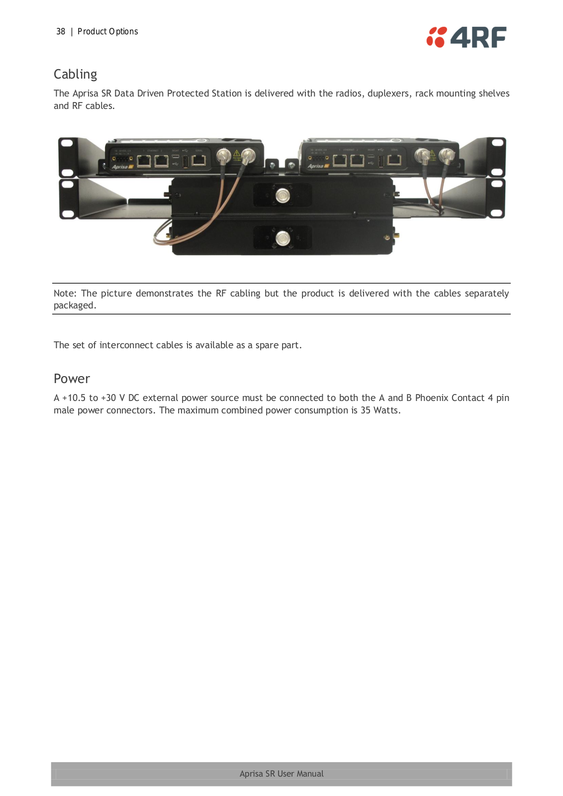
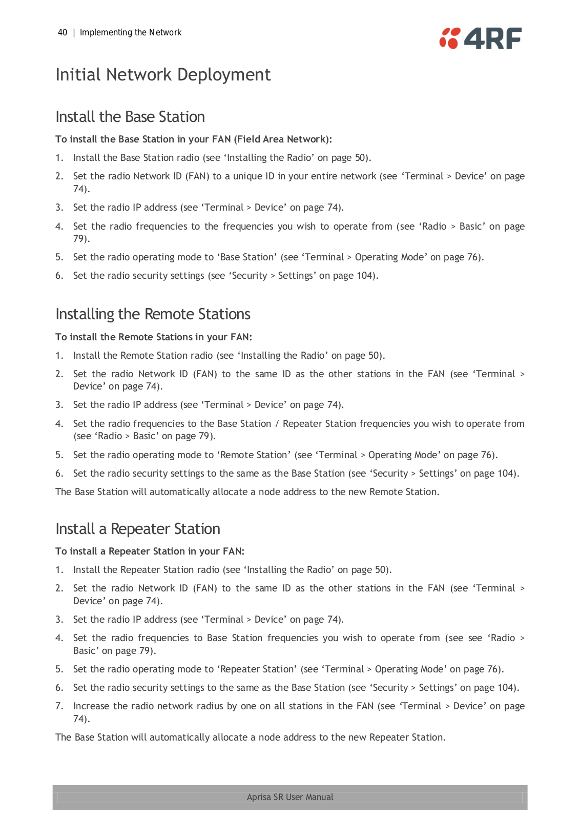
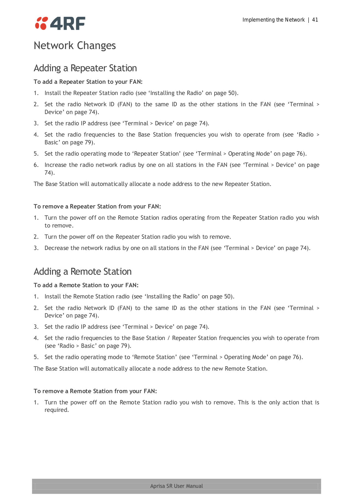
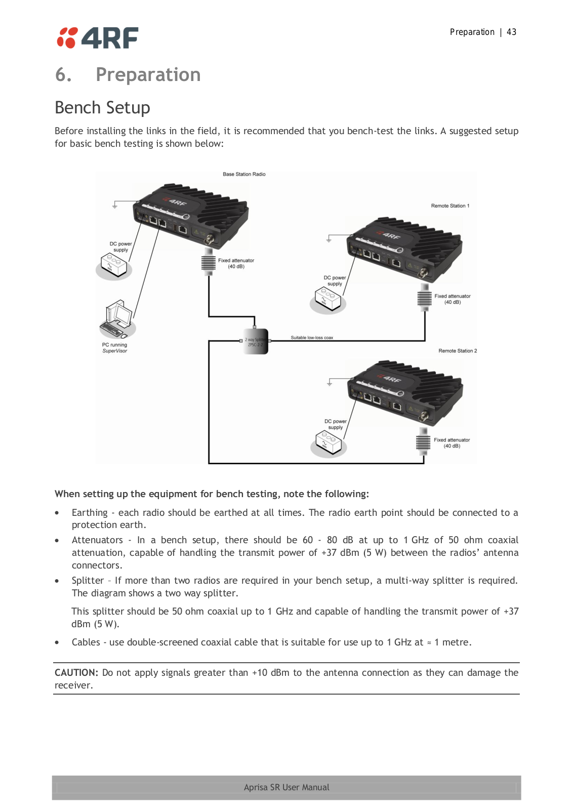
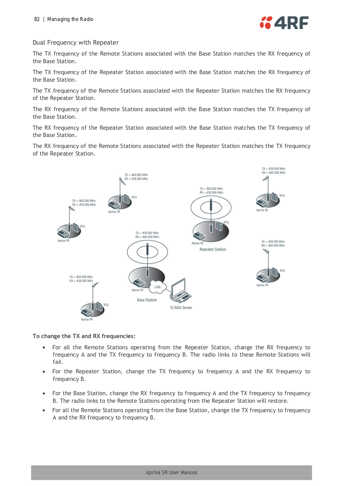
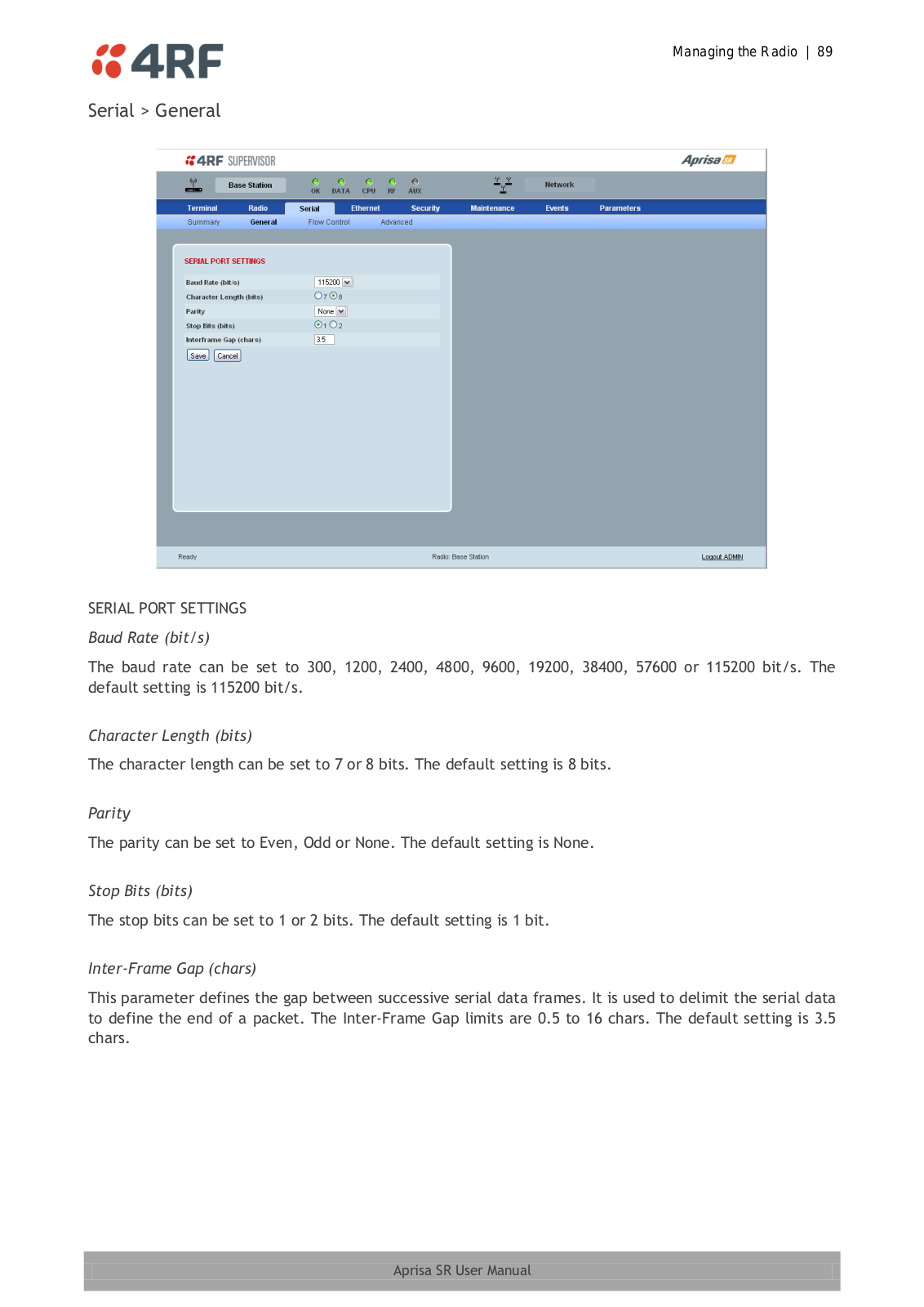
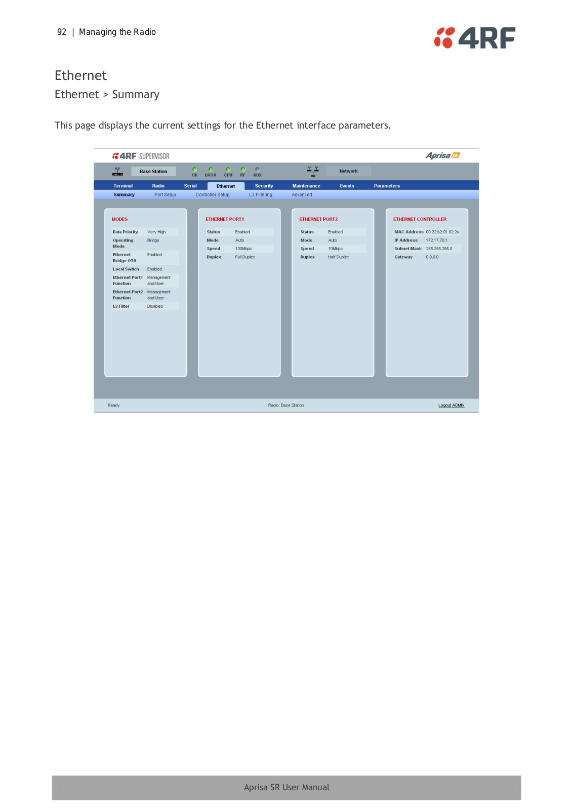
4RF Aprisa SR User Manual
...
4RF User Manual
Download
Specifications and Main Features
Frequently Asked Questions
User Manual
Download
Loading...
+
hidden pages
Unhide
You need points to download manuals.
1 point = 1 manual.
You can buy points or you can get point for every manual you upload.
Buy points
Upload your manuals
 Loading...