


 Loading...
Cross Connections | 134
QJET cross connections
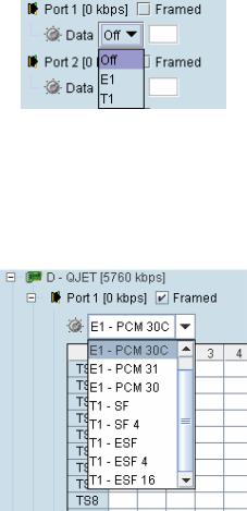
Expand the E1 / T1 display by clicking on the relevant icons.
The QJET card can operate in several modes allowing you greater flexibility in tailoring or grooming traffic. The Data type selection are Off, E1, or T1 rates.
Note: An unframed E1 / T1 port requires 5 bits (or 40 kbit/s) of overhead traffic per port for synchronization.
An unframed E1 port with 2048 kbit/s of traffic requires 2088 kbit/s of link capacity. An unframed T1 port with 1544 kbit/s of traffic requires 1584 kbit/s of link capacity.
Cross Connections | 135
For each port that you want to put into service, choose the required mode (either Unframed or Framed):
Unframed mode
Leave the Framed checkbox unticked.
Select the required Data type from the drop-down list E1 or T1.
Local drop and insert connections are not possible between Unframed E1 / T1 ports.
Framed mode
Tick the Framed checkbox.
Select the required framed mode from the drop-down list:
Local drop and insert connections are possible between framed E1 ports on the same interface card or E1 ports on different interface cards.
Local drop and insert connections are possible between framed T1 ports on the same interface card or T1 ports on different interface cards.
Local drop and insert connections are not possible between framed E1 ports and framed T1 ports.
Cross Connections | 136
E1 Framed Modes
Framed Mode |
Description |
|
|
|
|
E1 |
– PCM 30 |
Provides 30 timeslots to transport traffic. Timeslot 16 carries channel |
|
|
associated signalling data (CAS). |
E1 |
– PCM 31 |
Provides 31 timeslots to transport traffic. Timeslot 16 can be used for common |
|
|
channel signalling or to transport traffic. |
E1 |
– PCM 30C |
Same as E1 – PCM 30 mode but supports CRC-4. |
|
|
|
E1 |
– PCM 31C |
Same as E1 – PCM 31 mode but supports CRC-4. |
|
|
|
E1 CRC-4 (cyclic redundancy check) is used to ensure correct frame alignment and also used to gather E1 performance statistics e.g. Errored Seconds (ES), Severely Errored Seconds (SES).
The first three bits of timeslot 0 NFAS (bits 0,1 & 2) and all of timeslot 0 FAS are not transported across the link, but rather terminated and regenerated at each terminal.
The last five bits of timeslot 0 NFAS (bits 3 – 7) are the National Use Bits (NUBs) which can be cross connected locally or over the link.
E1 - PCM 30 mode
E1 - PCM 30 modes are used when access to the signalling bits (ABCD) is required, for example:
Splitting a PCM 30 E1 into two separate PCM 30 E1s
Cross connecting signalling from DFXS, DFXO or Q4EM interfaces into an PCM 30 E1
Drop and Insert connections between PCM 30 E1s
In PCM 30 / PCM 30C mode, the timeslot table left column is used to map timeslot bits and the timeslot table right column is used to map CAS bits (ABCD) for signalling. Timeslot 16 is reserved to transport the CAS multi frame.
One use of this mode is to connect the 4 wire E&M interfaces to third-party multiplexer equipment over the E1 interface using CAS in TS16 to transport the E&M signalling.
To configure this mode correctly, you must have a detailed knowledge of the CAS signalling modes for the third-party equipment to ensure the signalling bits are compatible and configured to interoperate.
E1 - PCM 31 mode
E1 - PCM 31 modes are used to cross connect timeslots bits without the signalling bits (ABCD).
TS16 can be cross connected between E1 ports (to transport the entire CAS multi frame) or used for common channel signalling or to transport traffic.
The timeslot table left column is used to map timeslot bits but the timeslot table right column for CAS bits (ABCD) is not used.
Cross Connections | 137
T1 Framed Modes
Framed Mode |
Description |
|
|
|
|
T1 |
- SF |
Provides 24 timeslots to transport traffic using the G.704 12 frame Super |
|
|
Frame without signalling. There is no CRC capability with the SF. |
|
|
|
T1 |
– SF 4 |
Provides 24 timeslots to transport traffic using the G.704 12 frame Super |
|
|
Frame with 4 state signalling (AB bits). There is no CRC capability with the SF. |
|
|
|
T1 |
– ESF |
Provides 24 timeslots to transport traffic using the G.704 24 frame Extended |
|
|
Super Frame with CRC and without signalling. |
|
|
|
T1 |
– ESF 4 |
Provides 24 timeslots to transport traffic using the G.704 24 frame Extended |
|
|
Super Frame with CRC and 4 state signalling (AB bits). |
|
|
|
T1 |
– ESF 16 |
Provides 24 timeslots to transport traffic using the G.704 24 frame Extended |
|
|
Super Frame with CRC and 16 state signalling (ABCD bits). |
|
|
|
For the 24 framed modes of ESF 4 and ESF 16, the Data Link bit is shown in the timeslot table but is currently unavailable for use.
T1 - SF mode
T1 SF mode provides 24 timeslots to transport traffic using the G.704 12 frame Super Frame without demultiplexing the signalling. Complete timeslots can be cross connected including the inherent robbed signalling bits.
The timeslot table left column is used to map timeslot bits but the timeslot table right column for CAS bits (ABCD) is not used.
T1 SF mode is used when access to the signalling bits is not required but are transported between T1s, for example:
Drop and Insert connections between 12 frame Super Frame T1s or data interfaces
T1 - SF 4 mode
T1 SF 4 mode provides 24 timeslots to transport traffic using the G.704 12 frame Super Frame with four state demultiplexed signalling using the AB bits.
The mapping left column is used to map timeslot bits and the timeslot table right column is used to map the CAS A&B bits for signalling (C&D bits are not used).
T1 SF mode is used when access to the signalling bits is required, for example:
Cross connecting signalling from DFXS, DFXO or Q4EM interfaces into a 12 frame Super Framed T1 using ‘multiplexed’ signalling from the interface.
Drop and Insert connections between 12 frame Super Framed T1s or data interfaces
T1 - ESF mode
T1 ESF mode provides 24 timeslots to transport traffic using the G.704 12 frame Extended Super Frame without demultiplexing the signalling. Complete timeslots can be cross connected including the inherent robbed signalling bits.
The timeslot table left column is used to map timeslot bits but the timeslot table right column for CAS bits (ABCD) is not used.
T1 ESF mode is used when access to the signalling bits is not required but are transported between T1s, for example:
Drop and Insert connections between 24 frame Extended Super Framed T1s or data interfaces
Cross Connections | 138
T1 - ESF 4 mode
T1 ESF 4 mode provides 24 timeslots to transport traffic using the G.704 24 frame Extended Super Frame with four state demultiplexed signalling using the AB bits each with a bit rate of 667 bit/s.
The mapping left column is used to map timeslot bits and the timeslot table right column is used to map the CAS A&B bits for signalling (C&D bits are not used).
T1 ESF 4 mode is used when access to the signalling bits is required, for example:
Cross connecting signalling from DFXS, DFXO or Q4EM interfaces into a 24 frame Extended Super Framed T1 using ‘multiplexed’ signalling from the interface.
Drop and Insert connections between 24 frame Extended Super Framed T1s or data interfaces
T1 - ESF 16 mode
T1 ESF 16 mode provides 24 timeslots to transport traffic using the G.704 24 frame Extended Super Frame with sixteen state demultiplexed signalling using the ABCD bits each with a bit rate of 333 bit/s.
The mapping left column is used to map timeslot bits and the timeslot table right column is used to map the CAS ABCD bits for signalling.
T1 ESF 16 mode is used when access to the signalling bits is required, for example:
Cross connecting signalling from DFXS, DFXO or Q4EM interfaces into a 24 frame Extended Super Framed T1 using ‘non-multiplexed’ signalling from the interface.
Drop and Insert connections between 24 frame Extended Super Framed T1s or data interfaces
Cross Connections | 139
Selecting and mapping bits and timeslots
This section describes how to select and map:
a single bit
multiple bits
a 64 kbit/s timeslot
multiple timeslots
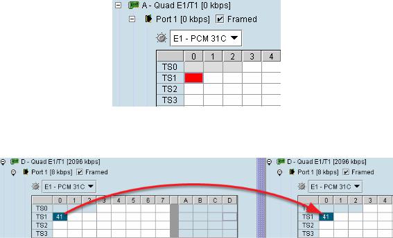
Selecting a single bit
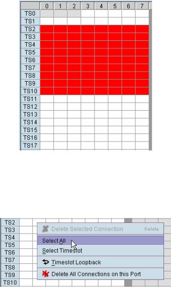
Each timeslot is represented by 8 rectangles (each representing a single bit). Each bit can carry 8 kbit/s.
One or more consecutive bits can be selected in a timeslot if a rate of greater than 8 kbit/s is required.
1. Click on the rectangle that represents the bit you require. It will turn red.
2. Click and drag this bit to the rectangle representing the bit on the interface you want it to be connected to, and release the mouse button.
The red rectangle will be replaced by the allocated connection number at each interface.
Cross Connections | 140
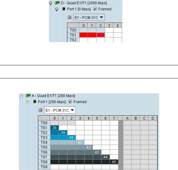
Selecting multiple bits
It is possible to select multiple consecutive bits if circuit capacity of greater than 8 kbit/s is required.
1. Click the first bit, and then hold down the Ctrl key while selecting the remaining bits.
2. Click and drag the whole block by clicking the bit on the left hand side of your selection, and drag to the required interface. Release the mouse button.
Tip: It is also possible to select multiple bits by holding down the Shift key, and dragging across the required rectangles.
Differing numbers of bits display in different colors when the cross-connect is completed:
Cross Connections | 141
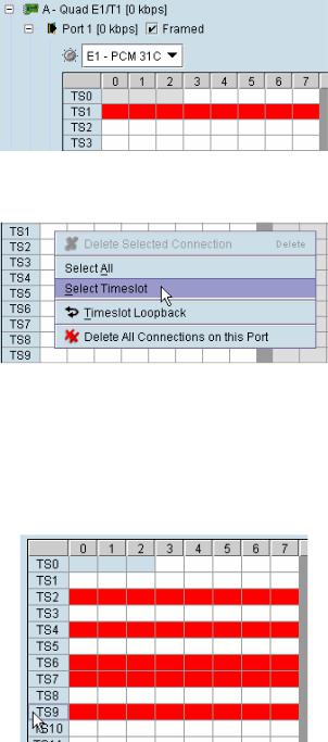
Selecting a 64 kbit/s timeslot
1. Click on the TSX timeslot number (where X is the desired timeslot from 1 to 31).
Alternatively, right-click over any of the bits in the timeslot, and click on Select Timeslot.
2. Drag and drop in the normal way to complete the cross connection.
Selecting multiple non consecutive timeslots
1.Click on one TSn timeslot number (where n is the desired timeslot 1 to 31).
2.Hold down the Ctrl key while clicking on each of the required timeslot numbers.
3. Drag and drop in the normal way to complete the cross connection.
Cross Connections | 142
Selecting multiple consecutive timeslots
1.Click on the first TSn timeslot number (where n is the desired timeslot 1 to 31).
2.Hold down the Shift key while clicking on the last required timeslot number.
3. Drag and drop in the normal way to complete the cross connection.
Selecting all timeslots in a port
1. Right-click over any of the rectangles.
2. Click Select All.
Cross Connections | 143
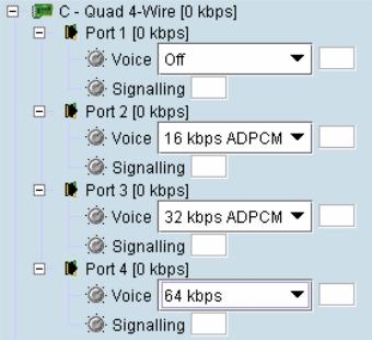
Q4EM cross connections
1. Expand the Q4EM display by clicking the relevant  icon.
icon.
2.Set the Voice capacity by selecting 16, 24, 32, or 64 kbit/s rates.
3.Drag and drop from the Voice mapping connection box to the required partner interface to create the voice cross connection.
4.If E&M signalling is required, drag and drop from the Signalling mapping connection box to the required partner interface to create the E&M cross connection.
Cross Connections | 144
DFXS & DFXO cross connections
1. On one side of the link, expand the DFXS display, as required, by clicking  .
.
2. On the other side of the link, expand the corresponding DFXO display, as required, by clicking  .
.
3. For the DFXS card and corresponding DFXO card, select the Signalling type as required, according to the table below. The CAS signalling between DFXO / DFXS interfaces uses 4RF proprietary allocation of control bits.
The Signalling type affects both ports of the DFXO / DFXS interface. If a mixture of signalling types is required, then multiple DFXO / DFXS cards are needed.
Signalling |
Application |
Overhead |
|
|
|
Multiplexed |
Multiplexers the four ABCD bits from the interface into a |
8 kbit/s |
(default) |
single 8 kbit/s channel. |
|
|
Use when interworking DFXO to DFXS, between an XE |
|
|
and a SE radio or when limited bandwidth is available. |
|
|
This signalling type cannot be used for interworking |
|
|
between framed E1 and voice interfaces. |
|
|
|
|
Non-multiplexed |
Transports each of the four ABCD bits in separate 8 kbit/s |
32 kbit/s |
|
channels. |
|
|
Use when interworking DFXO cards to DFXS cards or |
|
|
when signalling bits are mapped into an E1 / T1 timeslot. |
|
4 wire compatible |
Use when interworking the DFXO card or DFXS card to a |
8 kbit/s |
|
Q4EM interface |
|
|
• DFXS to DFXO A bit mapped to off-hook |
|
|
• DFXO to DFXS A bit mapped to fault |
|
|
|
|
4.Set the Voice capacity and create the Voice connection by dragging and dropping between the mapping connection boxes of the DFXO and DFXS corresponding ports.
5.Link the Port Signalling connection by dragging and dropping between the mapping connection boxes of the DFXO and DFXS corresponding ports. The DFXO / DFXS control signals (off hook, ring, etc) will not function without this connection.
Cross Connections | 145
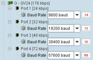
QV24 cross connections
1. Expand the QV24 displays, as required, by clicking the relevant  icons.
2.Select the Port Baud Rate as required (default is 9600).
3.Drag and drop to the required partner interface to create the V.24 Data connection. If the partner interface is a QJET:
If the V.24 Baud Rate selected is 38400 is less, drag from the QV24 mapping connection box to the QJET timeslot. The correct QJET capacity for the baud rate selected will automatically be assigned.
If the V.24 Baud Rate selected is greater than 38400, select the QJET capacity required, as per the following table, and drag from the QJET to the QV24 mapping connection box.
Baud Rate |
Bits Required |
Bit Rate |
|
|
|
|
|
300 |
- 7200 |
2 |
16 kbit/s |
|
|
|
|
9600 |
- 14400 |
3 |
24 kbit/s |
|
|
|
|
19200 - 23040 |
4 |
32 kbit/s |
|
|
|
|
|
28800 |
5 |
40 kbit/s |
|
|
|
|
|
38400 |
6 |
48 kbit/s |
|
|
|
|
|
57600 |
9 |
72 kbit/s |
|
|
|
|
|
115200 |
16 |
128 kbit/s |
|
|
|
|
|
Cross Connections | 146
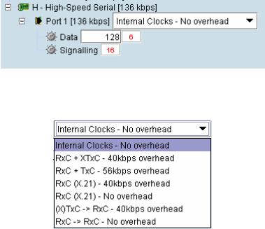
HSS cross connections
1. Expand the HSS displays, as required, by clicking the relevant  icons.
2. Select the Synchronous Clock Selection mode (see “HSS synchronous clock selection modes” on page 114).
3.Set the Data rate to a value between 8 and 2048 (in multiples of 8 kbit/s). The net data rate available to the user is defined by Data Rate – overhead
e.g. a date rate set to 2048 kbit/s with an overhead of 40 kbit/s provides a user data rate of 2008 kbit/s
4.Drag and drop to the required partner interface to create the HSS Data connection.
If the partner interface is a QJET, select the capacity on the QJET and drag it to the HSS Data mapping connection box.
The QJET capacity selected must be the sum of the data rate required plus the overhead rate selected.
5.Drag and drop to the required partner interface to create the HSS Signalling cross connection. A minimum of 8 kbit/s of capacity is required and must be set symmetrically at both ends of the link.
Cross Connections | 147
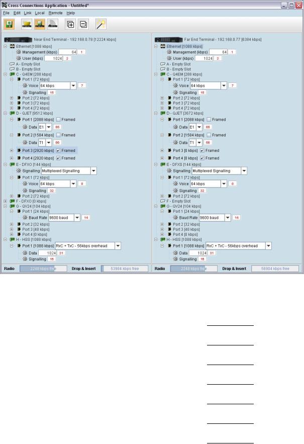
Cross connection example
This is an example of cross connection mapping:
Circuit |
Local port |
Remote port |
Capacity |
Connection |
|
|
|
(kbit/s) |
numbers |
|
|
|
|
|
Radio management |
|
|
64 |
1 |
|
|
|
|
|
User Ethernet |
|
|
1024 |
2 |
|
|
|
|
|
3 wire E&M circuit |
Q4EM port 1 |
Q4EM port 1 |
72 |
7/15 |
|
(slot C) |
(slot C) |
|
|
Unframed E1 data |
QJET port 1 |
QJET port 1 |
2088 |
65 |
|
(slot D) |
(slot D) |
|
|
Unframed T1 data |
QJET port 2 |
QJET port 2 |
1584 |
66 |
|
(slot D) |
(slot D) |
|
|
Loop Interface |
DFXO port 1 |
DFXS port 1 |
72 |
8/32 |
|
(slot E) |
(slot E) |
|
|
V.24 data circuit |
QV24 port 1 |
QV24 port 1 |
24 |
14 |
9600 |
(slot G) |
(slot G) |
|
|
HSS data circuit |
HSS port 1 |
HSS port 1 |
1088 |
31/16 |
1024 kbit/s |
(slot H) |
(slot H) |
|
|

Cross Connections | 148
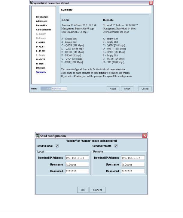
Symmetrical Connection Wizard
The Cross Connections application has a Symmetrical Connection Wizard which simplifies the cross connection configuration when the terminals are fitted with symmetrical / matching interface types.
A symmetrical connection is a connection between the local and the remote terminal where the local slot, card type, port and connection details are identical to those of the remote terminal.
The only exception is DFXO / DFXS connections where DFXO cards are considered to match DFXS cards (as they normally interwork).
Framed E1 / T1 CAS connections, drop-and-insert connections, and connections that do not involve entire timeslots, are considered to be asymmetrical.
Starting the wizard
When starting the wizard with unsaved changes, the following popup dialog should appear
Click on 'Save' if you wish to save the current configuration to a file. Clicking on 'Continue' will continue with the wizard and overwrite any changes made when the wizard finishes.
The wizard can be cancelled at any time by clicking on the 'Cancel' button or by closing the window.
Wizard Navigation
Click on the Next button to progress through the wizard. The current stage is indicated in the navigation bar on the left. You can jump directly to a stage by clicking on the stage required.
Cross Connections | 149
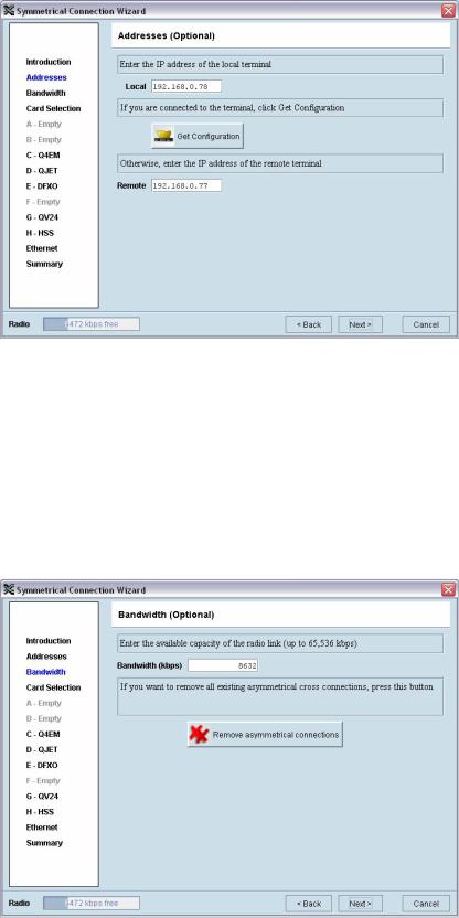
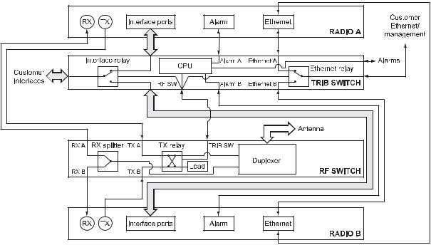
Setting the IP address
If the local or remote terminal IP addresses have been setup, they will be displayed in the Local and Remote fields. If the IP addresses are not displayed, enter the IP addresses of the local and remote terminals.
Click on 'Get Configuration' to upload the existing cross connections configuration from the local terminal. The Radio bandwidth bar will show the available bandwidth and will be updated as bandwidth is assigned to cards.
Setting the bandwidth
If the Cross Connections Application is opened from SuperVisor, the Total Capacity of the radio link will be shown in the Bandwidth field.
If the Cross Connections Application is opened as a stand alone application, the Total Capacity of the radio link will be need to be entered in the Bandwidth field.
The 'Remove asymmetrical connections' button will be active if there are existing asymmetrical cross connections. If you want to remove existing asymmetrical cross connections, click on this button. The Radio bandwidth bar will update accordingly.
Cross Connections | 150
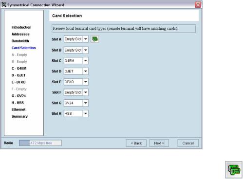
Card Selection
If the Cross Connections Application is opened from SuperVisor, existing cards installed in the local terminal that match cards installed in the remote terminal will be displayed. Mismatched cards will be shown as 'Empty Slot'.
If the Cross Connections Application is opened as a stand alone application, select the card types that will be fitted in the terminal.
To copy the card type selected in Slot A to all the other slots (B – H), click on the Copy Card button. This assumes that the same interface card types are fitted in all the card slots.
Cross Connections | 151
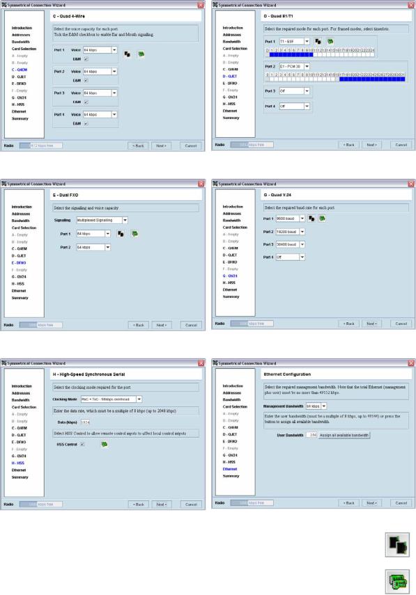
Interface configurations
Setup the interface configurations as per the wizard instructions. Existing asymmetrical connections will be replaced with symmetrical connections if an interface parameter is changed.
Q4EM |
QJET |
DFXO / DFXS |
QV24 |
HSS |
Ethernet |
To copy the port configuration selected in Port 1 to all the other ports on the card, click on the Copy Port button.
To copy the card configuration to all other cards of the same type fitted in the terminal, click on the Copy Card button. This can save time when setting up multiple cards of the same type.
Cross Connections | 152
Symmetrical connection summary
Click Finish.
Send symmetrical connection configuration
Click OK to send the configuration to the terminals.
The process is completed.
Note: The wizard may change the connection numbers of existing connections.
Protected terminals | 153
11. Protected terminals
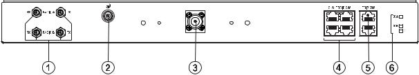
Monitored Hot Stand By (MHSB)
This section describes configuring the protected terminal in MHSB mode. A protected terminal in MHSB mode comprises two radios interconnected using the tributary and RF switches as shown below:
The MHSB switch protects terminals against any single failure in one radio. It also monitors the alarm output of each radio and switches between radios if major radio link alarms occur.
The MHSB switch uses a CPU to monitor the alarm status received from both the connected radios' alarm ports. When a relevant major radio link alarm is detected on the active radio (that is, transmitter, receiver, power supply or modem), the CPU switches a bank of relays that switches all the interfaces and the transmit port from the main radio to a functioning stand-by radio. The stand-by radio now becomes the active radio.
The tributary switch and the RF switch are both a 19-inch rack-mount 1U high chassis. The total rack space required is 6U. The MHSB switch option is available for the following bands: 300, 400, 700, 900, 1400, 2000, and 2500 MHz.
Protected terminals | 154
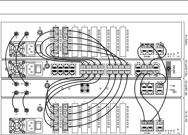
Tributary switch front panel
No. |
Description |
Explanation |
|
|
|
1 |
Power supply input |
Input for DC power or AC power |
|
|
|
2 |
Protective earth |
M5 terminal intended for connection to an external protective |
|
|
conductor for protection against electric shock in case of a fault |
|
|
|
3 |
Interface ports |
Port for connecting to customer interface equipment |
|
|
|
4 |
Radio A interfaces |
These connect to the interface ports on radio A |
|
|
|
5 |
Radio B interfaces |
These connect to the interface ports on radio B |
|
|
|
6 |
Console |
For factory use only |
|
|
|
7 |
Ethernet |
Port for connecting to customer Ethernet network. This port is also |
|
|
used to set up and manage the radios remotely over an IP |
|
|
network |
|
|
|
8 |
Radio A Ethernet |
Connects to an Ethernet port on radio A |
|
|
|
9 |
Radio B Ethernet |
Connects to an Ethernet port on radio B |
|
|
|
10 |
Alarms |
Alarm input/output connections for customer equipment |
|
|
|
11 |
Radio A alarms |
Connects to the alarm port on radio A |
|
|
|
12 |
Radio B alarms |
Connects to the alarm port on radio B |
|
|
|
13 |
RF SW |
Provides power and signalling to the RF switch |
|
|
|
14 |
Mode switch |
Three-position locking toggle switch to set the MHSB switch into |
|
|
automatic mode or radio A / radio B test mode |
|
|
|
15 |
LEDs |
Mode and status LEDs |
|
|
|
|
|
|
Protected terminals | 155 |
Tributary protection switch LEDs |
|
||
|
|
|
|
LED |
Colour |
Appearance |
Explanation |
|
|
|
|
A |
Green |
Solid |
The radio is active and is OK |
|
|
|
|
|
Green |
Flashing |
The radio is in standby mode and is OK |
|
|
|
|
|
Red |
Solid |
The radio is active and there is a fault |
|
|
|
|
|
No colour (off) |
- |
The tributary switch is in 'slave' mode and the |
|
|
|
switching is controlled by the master tributary |
|
|
|
switch |
|
|
|
|
|
Red |
Flashing |
The radio is in standby mode, and there is a fault |
|
|
|
|
B |
Green |
Solid |
The radio is active and is OK |
|
|
|
|
|
Green |
Flashing |
The radio is in standby mode and is OK |
|
|
|
|
|
Red |
Solid |
The radio is active and there is a fault |
|
|
|
|
|
No colour (off) |
- |
The tributary switch is in 'slave' mode and the |
|
|
|
switching is controlled by the master tributary |
|
|
|
switch |
|
|
|
|
|
Red |
Flashing |
The radio is in standby mode, and there is a fault |
|
|
|
|
~ |
Green |
Solid |
The tributary protection switch is in 'auto' mode |
|
|
|
|
|
Green |
Flashing |
The tributary protection switch is in 'slave' mode |
|
|
|
|
|
Red |
Solid |
The tributary protection switch is in 'manual' mode |
|
|
|
(A or B) |
|
|
|
|
On |
Blue |
Solid |
Indicates that there is power to the tributary |
|
|
|
protection switch |
|
|
|
|
RF switch front panel
No. |
Description |
Explanation |
|
|
|
1 |
Radio QMA |
QMA connectors for connecting the protected radios |
|
|
|
2 |
Protective earth |
M5 terminal intended for connection to an external protective |
|
|
conductor for protection against electric shock in case of a fault |
|
|
|
3 |
Antenna port |
N-type female connector for connection to the antenna feeder |
|
|
cable. This view shows an internally mounted duplexer. If an |
|
|
external duplexer is fitted, the antenna port will be on the external |
|
|
duplexer |
4 |
Slave tributary switch |
Connects to secondary tributary switch for control of additional |
|
outputs |
interfaces |
5 |
Tributary switch |
Connects the RF switch to the tributary switch (the master if more |
|
|
than one tributary switch is required) |
6 |
LEDs |
Status LEDs |
|
|
|

|
|
|
Protected terminals | 156 |
RF protection switch LEDs |
|
||
|
|
|
|
LED |
Colour |
Appearance |
Explanation |
|
|
|
|
Tx A |
Green |
Solid |
RF is being received from radio A |
|
|
|
|
Tx B |
Green |
Solid |
RF is being received from radio B |
|
|
|
|
On |
Blue |
Solid |
Indicates that there is power to the RF protection switch |
|
|
|
|
Slave tributary switches
Each tributary switch protects up to eight ports. Up to three slave tributary switches may be added to a MHSB terminal to protect up to 32 ports. Each slave tributary switch is interconnected by means of the slave tributary switch ports on the RF switch, as shown below.
Note: A tributary switch that is operating as a slave (rather than a master) has a RJ-45 V.24 loopback connector plugged into the console port. If the connector is missing, contact Customer Support. Alternatively, you can make this connector. Follow the standard pinouts for a V.24 RJ-45 connection (see "QV24 Interface connections" on page 228).
Protected terminals | 157
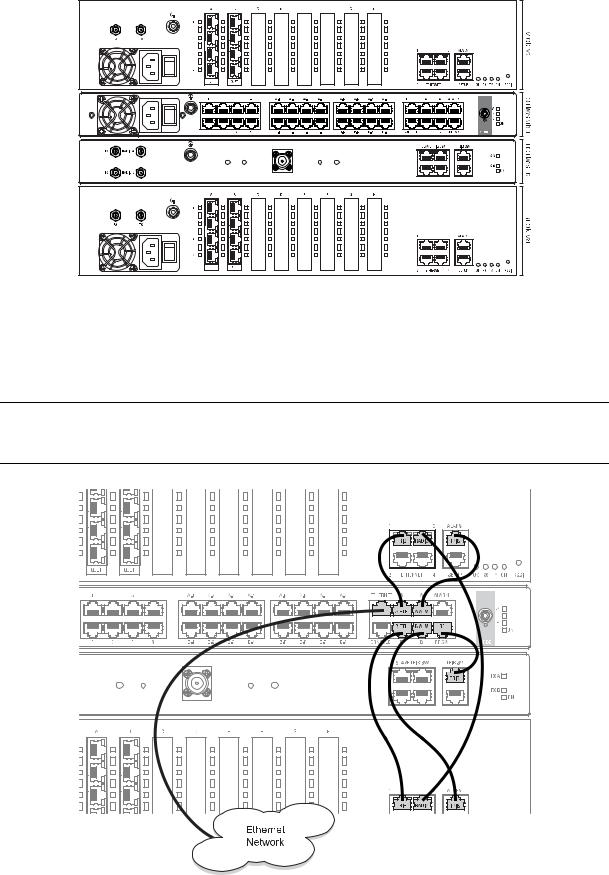
MHSB cabling
The two radios are interconnected as follows:
Caution: Do not connect Transmit to Receive or Receive to Transmit as this may damage the radio or the MHSB switch.
Cables supplied with MHSB
The following cables are supplied with a MHSB terminal:
Ethernet interface: RJ-45 ports standard TIA-568A patch cables .
Alarm interface: RJ-45 ports standard TIA-568A patch cables.
RF ports: two QMA male patch cables are supplied.
MHSB power supply
See “DC power supply” on page 32 and “AC power supply” on page 35.
Protected terminals | 158
Configuring the radios for protected mode
The MHSB switch does not require any special software. However, the radios connected to the MHSB switch must be configured to work with the MHSB switch. This sets the alarm outputs and inputs to function in MHSB mode.
You must configure the interfaces of both radios connected to the MHSB switch identically. To perform this, you can either connect directly to the radio or use the test mode of the MHSB switch.
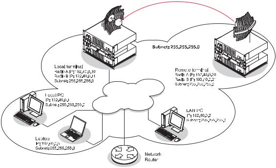
IP address setup
Before configuring the link, you must ensure that the two independent links have correctly configured IP address details.
All four radios in the protected link must be on the same subnet.
Protected terminals | 159
Mounting the MHSB radios and switch
Once the IP addresses are correctly configured, it is important to connect the A and B radios' Ethernet and Alarm ports correctly. In general, mount radio A above the MHSB switch and radio B below the MHSB switch:
There is an Ethernet connection between any of the four Ethernet ports on each radio and the Ethernet port on the Tributary switch. There is also a connection between radio A and radio B, which ensures Ethernet traffic is maintained if a radio loses power.
The Ethernet port on the protection switch can be connected to an Ethernet hub or switch to allow multiple connections.
Important: The management Ethernet capacity on each of the four radios in the protected terminal must be identical for remote communications to work and there should only be one IP connection to the management network (via the tributary switch Ethernet port).
Protected terminals | 160
Configuring the terminals for MHSB
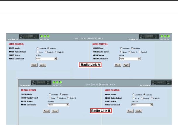
It is recommended that you configure the local and remote A side first, then the local and remote B side. Both the local A and B radios must be configured identically, and both the remote A and B radios must be configured identically.
Tip: As illustrated below, you may find it helpful to have two browser sessions running simultaneously. You can then easily see both the A and B sides of the protected link.
To configure MHSB operation:
1. Select Link > Maintenance > MHSB.
2.Enable MHSB mode.
3.Select whether the radio is A or B.
Ensure that the radio connected to the A side of the protection switch (normally above the MHSB switch) is set to Radio A and the radio connected to the B side of the protection switch (normally below the MHSB switch) is set to Radio B.
In the event of a power outage, the radios will switch over to the A side of the protection switch when the power is restored. The A side is also the default active side.
4.When you have made your changes, click Apply to apply changes or Reset to restore the previous configuration.
5.Repeat steps 2 to 4 for the other side of the protected link.
Protected terminals | 161
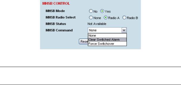
Clearing MHSB alarms
If a switchover event occurs, the OK LED on the front panel and on the Terminal status and menu bar in SuperVisor changes to orange.
1. Select Clear Switched Alarm from the MHSB Command drop-down list.
2. Click Apply to apply changes or Reset to reset the page.
Note: When MHSB mode is enabled, external alarm input 2 is used by the protection system to carry alarms from the protection switch to the radio. In MHSB mode, therefore, only external alarm input 1 is available for user alarms.
In-service commissioning | 163
12. In-service commissioning
Before you start
When you have finished installing the hardware, RF and the traffic interface cabling, the system is ready to be commissioned. Commissioning the terminal is a simple process and consists of:
1.Powering up the terminals
2.Configuring both the local and remote terminals using SuperVisor
3.Aligning the antennas
4.Synchronizing the terminals
5.Testing the link is operating correctly. As a minimum, conduct the suggested tests to ensure correct operation. More extensive testing may be required to satisfy the end client or regulatory body requirements.
6.Connecting up the client or user interfaces
What you will need
Appropriately qualified commissioning staff at both ends of the link.
Safety equipment appropriate for the antenna location at both ends of the link.
Communication equipment, that is, mobile phones or two-way radios.
SuperVisor software running on an appropriate laptop, computer, or workstation at one end of the link.
Tools to facilitate loosening and re-tightening the antenna pan and tilt adjusters.
Predicted receiver input levels and fade margin figures from the radio link budget (You can use Surveyor (see "Path planning" on page 19) to calculate the RSSI, fade margin, and availability).
Loading...