


January 2014
Version 1.1.6


| 1
Aprisa SR+ Product Description
Copyright
Copyright © 2014 4RF Limited. All rights reserved.
This document is protected by copyright belonging to 4RF Limited and may not be reproduced or
republished in whole or part in any form without the prior written permission of 4RF Limited.
Trademarks
Aprisa and the 4RF logo are trademarks of 4RF Limited.
Windows is a registered trademark of Microsoft Corporation in the United States and other countries. Java
and all Java-related trademarks are trademarks or registered trademarks of Sun Microsystems, Inc. in the
United States and other countries. All other marks are the property of their respective owners.
Disclaimer
Although every precaution has been taken preparing this information, 4RF Limited assumes no liability for
errors and omissions, or any damages resulting from use of this information. This document or the
equipment may change, without notice, in the interests of improving the product.
RoHS and WEEE compliance
The Aprisa SR+ is fully compliant with the European Commission’s RoHS (Restriction of Certain Hazardous
Substances in Electrical and Electronic Equipment) and WEEE (Waste Electrical and Electronic Equipment)
environmental directives.
Restriction of hazardous substances (RoHS)
The RoHS Directive prohibits the sale in the European Union of electronic equipment containing these
hazardous substances: lead, cadmium, mercury, hexavalent chromium, polybrominated biphenyls (PBBs),
and polybrominated diphenyl ethers (PBDEs).
4RF has worked with its component suppliers to ensure compliance with the RoHS Directive which came
into effect on the 1st July 2006.
End-of-life recycling programme (WEEE)
The WEEE Directive concerns the recovery, reuse, and recycling of electronic and electrical equipment.
Under the Directive, used equipment must be marked, collected separately, and disposed of properly.
4RF has instigated a programme to manage the reuse, recycling, and recovery of waste in an
environmentally safe manner using processes that comply with the WEEE Directive (EU Waste Electrical
and Electronic Equipment 2002/96/EC).
4RF invites questions from customers and partners on its environmental programmes and compliance with
the European Commission’s Directives (sales@4RF.com).

2 |
Aprisa SR+ Product Description
12.5 kHz and 25 kHz Channel
Radio performance
EN 300 113-2
EMC
EN 301 489 Parts 1 & 5
Environmental
EN 300 019, Class 3.4
Ingress Protection code IP51
Safety
EN 60950-1:2006
Class 1 div 2 for hazardous locations
Frequency band
Channel size
Power input
Notified
body
135-175 MHz
12.5 kHz, 25 kHz
12 VDC
320-400 MHz
12.5 kHz, 25 kHz
12 VDC
400-470 MHz
12.5 kHz, 25 kHz
12 VDC
450-520 MHz
12.5 kHz, 25 kHz
12 VDC
Compliance General
The Aprisa SR+ radio predominantly operates within frequency bands that require a site license be issued
by the radio regulatory authority with jurisdiction over the territory in which the equipment is being
operated.
It is the responsibility of the user, before operating the equipment, to ensure that where required the
appropriate license has been granted and all conditions attendant to that license have been met.
Changes or modifications not approved by the party responsible for compliance could void the user’s
authority to operate the equipment.
Equipment authorizations sought by 4RF are based on the Aprisa SR+ radio equipment being installed at a
fixed restricted access location and operated in point-to-multipoint or point-to-point mode within the
environmental profile defined by EN 300 019, Class 3.4. Operation outside these criteria may invalidate
the authorizations and / or license conditions.
The term ‘Radio’ with reference to the Aprisa SR+ User Manual, is a generic term for one end station of a
point-to-multipoint Aprisa SR+ network and does not confer any rights to connect to any public network or
to operate the equipment within any territory.
Compliance European Telecommunications Standards Institute
The Aprisa SR+ radio is designed to comply with the European Telecommunications Standards Institute
(ETSI) specifications as follows:

| 3
Aprisa SR+ Product Description
Radio
47CFR part 24, part 90 and part 101 Private Land Mobile
Radio Services
EMC
47CFR part 15 Radio Frequency Devices, EN 301 489 Parts
1 & 4
Environmental
EN 300 019, Class 3.4
Ingress Protection code IP51
Safety
EN 60950-1:2006
Class 1 div 2 for hazardous locations
Frequency Band
Channel size
Power
input
Authorization
FCC ID
135-175 MHz
12.5 kHz, 25 kHz
12 VDC
Part 90
Pending
50 kHz
400-470 MHz
12.5 kHz, 25 kHz
12 VDC
Part 90
UIPSQ400M131
450-520 MHz
12.5 kHz, 25 kHz
12 VDC
Part 90
Pending
896-902 MHz
12.5 kHz, 25 kHz
12 VDC
Part 90
Pending
896-902 MHz
12.5 kHz, 25 kHz,
50 kHz
12 VDC
Part 24
Pending
928-960 MHz
12.5 kHz, 25 kHz,
50 kHz
12 VDC
Part 24 and
Part 101
Pending
216-220 MHz
12.5 kHz, 25 kHz,
12 VDC
Part 90
Pending
Compliance Federal Communications Commission
The Aprisa SR+ radio is designed to comply with the Federal Communications Commission (FCC)
specifications as follows:
NOTE: This equipment has been tested and found to comply with the limits for a Class A digital device,
pursuant to part 15 of the FCC Rules. These limits are designed to provide reasonable protection against
harmful interference when the equipment is operated in a commercial environment. This equipment
generates, uses, and can radiate radio frequency energy and, if not installed and used in accordance with
the instruction manual, may cause harmful interference to radio communications. Operation of this
equipment in a residential area is likely to cause harmful interference in which case the user will be
required to correct the interference at his own expense.

4 |
Aprisa SR+ Product Description
Radio
RSS-119 / RSS-134
EMC
This Class A digital apparatus complies with Canadian
standard ICES-003.
Cet appareil numérique de la classe A est conforme à la
norme NMB-003 du Canada.
Environmental
EN 300 019, Class 3.4
Ingress Protection code IP51
Safety
EN 60950-1:2006
Class 1 div 2 for hazardous locations
Frequency Band
Channel size
Power
input
Authorization
IC ID
135-175 MHz
12.5 kHz, 25 kHz
12 VDC
RSS-119
Pending
215-240 MHz
12.5 kHz, 25 kHz
12 VDC
RSS-119
Pending
400-470 MHz
12.5 kHz, 25 kHz
12 VDC
RSS-119
6772A-SQ400M131
896-902 MHz
12.5 kHz, 25 kHz
12 VDC
RSS-119
Pending
896-902 MHz
12.5 kHz, 25 kHz,
50 kHz
12 VDC
RSS-134
Pending
928-960 MHz
12.5 kHz, 25 kHz,
50 kHz
12 VDC
RSS-119 and
RSS-134
Pending
Compliance Industry Canada
The Aprisa SR+ radio is designed to comply with Industry Canada (IC) specifications as follows:
Compliance Hazardous Locations Notice
This product is suitable for use in Class 1, Division 2, Groups A - D hazardous locations or non-hazardous
locations.
The following text is printed on the Aprisa SR+ fascia:
WARNING: EXPLOSION HAZARD - Do not connect or disconnect while circuits are live unless area is known
to be non-hazardous.
The following text is printed on the Aprisa SR+ for product where the end user is in Canada:
AVERTISSEMENT: RISQUE D'EXPLOSION - Ne pas brancher ou débrancher tant que le circuit est sous
tension, à moins qu'il ne s'agisse d'un emplacement non dangereux.

| 5
Aprisa SR+ Product Description
WARNING:
The installer and / or user of Aprisa SR+ radios shall ensure that a separation distance
as given in the following table is maintained between the main axis of the terminal’s
antenna and the body of the user or nearby persons.
Minimum separation distances given are based on the maximum values of the
following methodologies:
1. Maximum Permissible Exposure non-occupational limit (B or general public) of
47 CFR 1.1310 and the methodology of FCC’s OST/OET Bulletin number 65.
2. Reference levels as given in Annex III, European Directive on the limitation of
exposure of the general public to electromagnetic fields (0 Hz to 300 GHz)
(1999/519/EC). These distances will ensure indirect compliance with the
requirements of EN 50385:2002.
Frequency (MHz)
Maximum Power
(dBm)
Note 1
Maximum Antenna
Gain (dBi)
Minimum Separation
Distance
(m)
135
+ 37
15
2.5
175
+ 37
15
2.5
215
+ 37
15
2.5
216.5
+ 37
15
2.5
217.5
+ 33
15
2.5
240
+ 37
15
2.5
320
+ 37
15
2.5
400
+ 37
15
2.5
450
+ 37
15
2.5
470
+ 37
15
2.5
520
+ 37
15
2.5
896
+ 37
28
7.5
902
+ 37
28
7.5
928
+ 37
28
7.5
960
+ 37
28
7.5
RF Exposure Warning
Note 1: The Peak Envelope Power (PEP) at maximum set power level is +41 dBm.


Contents | 7
Aprisa SR+ Product Description
Contents
1. Introduction ............................................................................ 11
The 4RF Aprisa SR+ Radio ...................................................................... 11
Product Overview ............................................................................... 12
Network Coverage and Capacity ....................................................... 12
Automatic Registration .................................................................. 12
Remote Messaging ........................................................................ 12
Product Features ................................................................................ 13
Functions .................................................................................. 13
Performance .............................................................................. 14
Usability ................................................................................... 14
System Gain vs FEC Coding ............................................................. 15
Architecture ...................................................................................... 16
Security ........................................................................................... 17
Interfaces ......................................................................................... 18
Antenna Interface ........................................................................ 18
Ethernet Interface ....................................................................... 18
RS-232 Interface .......................................................................... 18
USB Interfaces ............................................................................ 18
Protect Interface ......................................................................... 18
Alarms Interface .......................................................................... 18
Mounting .......................................................................................... 19
DIN Rail Mounting ........................................................................ 19
Rack Shelf Mounting ..................................................................... 21
Wall Mounting ............................................................................. 22
2. Product Options ....................................................................... 23
Interface Ports ................................................................................... 23
Protected Station ............................................................................... 24
Protected Ports ........................................................................... 24
Operation .................................................................................. 25
Switch Over ........................................................................ 25
Configuration Management ...................................................... 25
Data Driven Protected Station................................................................. 26
Operation .................................................................................. 26
Duplexer Kits ..................................................................................... 27
UHF Duplexer Kits ........................................................................ 27
VHF Duplexer Kits ........................................................................ 28
USB RS-232 Serial Port .......................................................................... 29
USB RS-232 operation .................................................................... 29

8 | Contents
Aprisa SR+ Product Description
3. Specifications .......................................................................... 30
RF Specifications ................................................................................ 30
Frequency Bands ......................................................................... 30
Channel Sizes ............................................................................. 31
Receiver ................................................................................... 34
Transmitter ............................................................................... 37
Modem ..................................................................................... 37
Data Payload Security ................................................................... 37
Interface Specifications ........................................................................ 38
Ethernet Interface ....................................................................... 38
RS-232 Asynchronous Interface ......................................................... 39
Hardware Alarms Interface ............................................................. 40
Protection Switch Specifications ....................................................... 40
Power Specifications ............................................................................ 41
Power Supply .............................................................................. 41
Power Consumption ...................................................................... 42
Power Dissipation ........................................................................ 42
General Specifications .......................................................................... 43
Environmental ............................................................................ 43
Mechanical ................................................................................ 43
Compliance ................................................................................ 44
4. Management ........................................................................... 45
SuperVisor ........................................................................................ 45
Viewing the Aprisa SR+ Terminal Settings ............................................ 46
Configuring the Aprisa SR+ Terminal Details ......................................... 47
Configuring the Aprisa SR+ RF Network Details ...................................... 47
Configuring the Aprisa SR+ Radio Settings ............................................ 48
Command Line Interface ....................................................................... 49
SNMP .............................................................................................. 49
LED Display Panel ............................................................................... 50
Normal Operation ........................................................................ 50
Single Radio Software Upgrade ......................................................... 51
Network Software Upgrade ............................................................. 51
Test Mode ................................................................................. 51
5. Applications ............................................................................ 52
Basic point-to-multipoint application ........................................................ 52
Advanced point-to-multipoint application with repeater ................................. 53
Multi-interface point-to-multipoint application ............................................ 54
Multi-hop Daisy Chain Repeaters in LBS Mode Application ................................ 55
Pseudo Peer to Peer using Base-Repeater Application .................................... 56

Contents | ix
6. Product Architecture ................................................................. 57
Product Operation .............................................................................. 57
Physical Layer ............................................................................. 57
Data Link Layer / MAC layer ............................................................ 57
Channel Access .................................................................... 57
Hop by Hop Transmission ......................................................... 58
Adaptive Coding Modulation ..................................................... 59
Network Layer ............................................................................ 60
Packet Routing ..................................................................... 60
Static IP Router .................................................................... 61
Bridge Mode with VLAN Aware .................................................. 63
VLAN Bridge Mode Description .................................................. 64
Avoiding Narrow Band Radio Traffic Overloading .................................... 66
Product Architecture ........................................................................... 68
Aprisa SR+ Radio Block Diagram ........................................................ 69
Aprisa SR+ Protected Station Block Diagram ......................................... 69
7. Contact Us .............................................................................. 70


Introduction | 11
Aprisa SR+ Product Description
1. Introduction
The 4RF Aprisa SR+ Radio
The 4RF Aprisa SR+ is a point-to-multipoint digital radio providing secure narrowband wireless data
connectivity for SCADA, infrastructure and telemetry applications.
The radios carry a combination of serial packet data and Ethernet data between the base station,
repeater stations and remote stations.
The Aprisa SR+ is configurable as a point-to-multipoint base station, a remote station or a repeater
station.

12 | Introduction
Aprisa SR+ Product Description
Product Overview
Network Coverage and Capacity
The Aprisa SR+ has a typical link range of up to 120 km, however, geographic features, such as hills,
mountains, trees and foliage, or other path obstructions, such as buildings, will limit radio coverage.
Additionally, geography may reduce network capacity at the edge of the network where errors may occur
and require retransmission. However, the Aprisa SR+ uses 10W output power and Forward Error Correction
(FEC) which greatly improves the sensitivity and system gain performance of the radio resulting in less
retries and minimal reduction in capacity.
Ultimately, the overall performance of any specific network will be defined by a range of factors including
the RF output power, the modulation used and its related receiver sensitivity, the geographic location,
the number of remote stations in the base station coverage area and the traffic profile across the
network. Effective network design will distribute the total number of remote stations across the available
base stations to ensure optimal geographic coverage and network capacity.
One base station can register and operate with up to 500 remote / repeater stations.
The practical limit of remote / repeater stations that can operate with one base station is determined by
a range of factors including the number of services, the packet sizes, the protocols used, the message
types and network timeouts.
Automatic Registration
On start-up, the remote station transmits a registration message to the base stations which responds with
a registration response. This allows the base station to record the details of all the remote stations active
in the network.
If a remote station cannot register with the base station after multiple attempts (RF LED flashing red)
within 10 minutes, it will automatically reboot. If a remote station has registered with the base station
but then loses communication, it will automatically reboot within 2 minutes.
Remote Messaging
There are two message types in the Aprisa SR+ network, broadcast messages and unicast messages.
Broadcast messages are transmitted by the base station to the remote stations and unicast messages are
transmitted by the remote station to the base station. These messages are commonly referred to as uplink
(unicast remote to base) and downlink (broadcast base to remote).
All remotes within the coverage area will receive broadcast messages and pass them on to either the
Ethernet or serial interface. The RTU determines if the message is intended for it and will accept it or
discard it.

Introduction | 13
Aprisa SR+ Product Description
Product Features
Functions
Point-to-point (PTP) or Point-to-multipoint (PMP) operation
Licensed frequency bands:
VHF 135 135-175 MHz
VHF 220 216-220 MHz
UHF 320 320-400 MHz
UHF 400 400-470 MHz
UHF 450 450-520 MHz
UHF 896 896-902 MHz
UHF 928 928-960 MHz
Channel sizes – software selectable:
12.5 kHz
25 kHz
50 kHz
Adaptive Coding Modulation (ACM): QPSK to 64 QAM
Half duplex or full duplex RF operation (full duplex channel access for point-to-multipoint
available in a future software release)
Ethernet data interface and RS-232 asynchronous multiple port options
Software selectable dual / single antenna port options (dual antenna port for external duplexers or
filters)
Data encryption and authentication using 128,192 and 256 bit AES and CCM security standards
Terminal server operation for transporting RS-232 traffic over IP or Ethernet
IEEE 802.1Q VLAN support with single and double VLAN tagged and add/remove VLAN manipulation
to adapt to the appropriate RTU / PLCs
QoS supports using IEEE 802.1p VLAN priority bits to prioritize and handle the VLAN / traffic types
L2/3/4 filtering for security and avoiding narrow band radio network overload
L3 Router mode with standard static IP route for simple routing network integration
L2 Bridge mode with VLAN aware for standard Industrial LAN integration
Ethernet header and IP/TCP/UDP ROCH header compression to increase the narrow band radio
capacity
Ethernet and serial payload compression to increase the narrow band radio capacity
Pseudo peer to peer communication between remote stations through base-repeater or repeater
stations
SuperVisor web management support for element and sub-network (base-repeater-remotes)
management
SNMPv1/2/3 & encryption MIB supports for 4RF SNMP manager or third party SNMP agent network
management
SNTP for accurate wide radio network time and date
Build-configuration / flexibility of serial and Ethernet interface ports (3+1, 2+2, 4+0)
Radio and user interface redundancy (provided with Aprisa SR+ Protected Station)
Protected Station fully hot swappable and monitored hot standby
Transparent to all common SCADA protocols; e.g. Modbus, IEC 60870-5-101/104, DNP3 or similar
Complies with international standards, including ETSI, FCC, IC, EMC, safety and environmental
standards

14 | Introduction
Aprisa SR+ Product Description
Performance
Typical deployment of 30 remote stations from one base station with a practical limit of a few
hundred remote stations
Long distance operation
High transmit power
Low noise receiver
Forward Error Correction
Electronic tuning over the frequency band
Thermal management for high power over a wide temperature range
Usability
Configuration / diagnostics via front panel Management Port USB interface, Ethernet interface
Built-in webserver SuperVisor with full configuration, diagnostics and monitoring functionality,
including remote station configuration / diagnostics over the radio link
LED display for on-site diagnostics
Dedicated alarm port
Software upgrade and diagnostic reporting via the host port USB flash drive
Over-the-air software distribution and upgrades
Simple installation with integrated mounting holes for wall, DIN rail and rack shelf mounting

Introduction | 15
Aprisa SR+ Product Description
Modulation
FEC Coding
Capacity
QPSK (High Gain)
Max Coded FEC
Minimum
QPSK (Low Gain)
Min Coded FEC
16QAM (High Gain)
Max Coded FEC
QPSK
No FEC
16QAM (Low Gain)
Min Coded FEC
16QAM
No FEC
64QAM (High Gain)
Max Coded FEC
64QAM (Low Gain)
Min Coded FEC
Maximum
Modulation
FEC Coding
Coverage
QPSK (High Gain)
Max Coded FEC
Maximum
QPSK (Low Gain)
Min Coded FEC
16QAM (High Gain)
Max Coded FEC
QPSK
No FEC
16QAM (Low Gain)
Min Coded FEC
64QAM (High Gain)
Max Coded FEC
16QAM
No FEC
64QAM (Low Gain)
Min Coded FEC
Minimum
System Gain vs FEC Coding
This table shows the relationship between modulation, FEC coding, system gain, capacity and coverage.
Maximum FEC coding results in the highest system gain, the best coverage but the least capacity
Minimum FEC coding results in lower system gain, lower coverage but higher capacity
No FEC coding results in the lowest system gain, the lowest coverage but the highest capacity
This table defines the modulation order based on gross capacity:
This table defines the modulation order based on receiver sensitivity:

16 | Introduction
Aprisa SR+ Product Description
Architecture
The Aprisa SR+ Architecture is based around a layered TCP/IP protocol stack:
Physical
Proprietary wireless
RS-232 and Ethernet interfaces
Link
Proprietary wireless (channel access, ARQ, segmentation)
VLAN aware Ethernet bridge
Network
Standard IP
Proprietary automatic radio routing table population algorithm
Transport
TCP, UDP
Application
HTTPS web management access through base station with proprietary management application
software including management of remote stations over the radio link
SNMPv1/2/3 for network management application software

Introduction | 17
Aprisa SR+ Product Description
Security
The Aprisa SR+ provides security features to implement the key recommendations for industrial control
systems. The security provided builds upon the best in class from multiple standards bodies, including:
IEC/TR 62443 (TC65) ‘Industrial Communications Networks – Network and System Security’
IEC/TS 62351 (TC57) ‘Power System Control and Associated Communications – Data and
Communication Security’
FIPS PUB 197, NIST SP 800-38C, IETF RFC3394, RFC3610 and IEEE P1711/P1689/P1685
The security features implemented are:
Data encryption
Counter Mode Encryption (CTR) using Advanced Encryption Standard (AES) 128, 192, 258 bit,
based on FIPS PUB 197 AES encryption (using Rijndael version 3.0)
Data authentication
NIST SP 800-38C Cipher Block Chaining Message Authentication Code (CBC-MAC) based on RFC
3610 using Advanced Encryption Standard (AES)
Data payload security
CCM Counter with CBC-MAC integrity (NIST special publication 800-38C)
Secured management interface protects configuration
L2 / L3 / L4 Address filtering enables traffic source authorization
Proprietary physical layer protocol and modified MAC layer protocol based on standardized IEEE
802.15.4
Licensed radio spectrum provides recourse against interference
SNMPv3 with Encryption for NMS secure access
Secure USB software upgrade
Key Encryption Key (KEK) based on RFC 3394, for secure Over The Air Re-keying (OTAR) of
encryption keys
User privilege allows the accessibility control of the different radio network users and the user
permissions

18 | Introduction
Aprisa SR+ Product Description
Interfaces
Antenna Interface
2 x TNC, 50 ohm, female connectors
Single or dual antenna ports (with or without the use of external duplexer/filter)
Ethernet Interface
2, 3 or 4 ports 10/100 base-T Ethernet layer 2 switch using RJ45
Used for Ethernet user traffic and radio sub-network management.
RS-232 Interface
2, 1 or 0 RS-232 asynchronous ports using RJ45 connector
Optional 1x RS-232 asynchronous port using USB host port with USB to RS-232 converter
Used for RS-232 asynchronous user traffic only.
USB Interfaces
1 x Management port using USB micro type B connector
Used for product configuration with the Command Line Interface (CLI).
1 x Host port using USB standard type A connector
Used for software upgrade and diagnostic reporting.
Protect Interface
1x Protect interface port
Used for the Protected Station operation.
Alarms Interface
1x Alarm port using RJ45 connector
Used to provide 2 x hardware alarm inputs and 2 x hardware alarm outputs

Introduction | 19
Aprisa SR+ Product Description
Part Number
Part Description
APSB-MBRK-DIN
4RF SR+ Acc, Mounting, Bracket, DIN Rail
Mounting
The Aprisa SR+ has four threaded holes (M4) in the enclosure base and two holes (5.2 mm) through the
enclosure for mounting.
Mounting options include:
DIN rail mounting with the Aprisa SR+ DIN Rail Mounting Bracket
Rack shelf mounting
Wall mounting
Outdoor enclosure mounting
DIN Rail Mounting
The Aprisa SR+ has an optional accessory to enable the radio to mount on a standard DIN rail:

20 | Introduction
Aprisa SR+ Product Description
The Aprisa SR+ DIN rail mounting bracket can be mounted in four positions on a horizontal DIN rail:
Vertical Mount (vertical enclosure perpendicular to the mount)
Horizontal Mount (horizontal enclosure perpendicular to the mount)
Flat Vertical Mount (vertical enclosure parallel to the mount)
Flat Horizontal Mount (horizontal enclosure parallel to the mount)

Introduction | 21
Aprisa SR+ Product Description
Part Number
Part Description
APSB-MR19-X1U
4RF SR+ Acc, Mounting, 19" Rack Mount Shelf, 1U
WARNING:
If the Aprisa SR+ is operated in an environment where the ambient temperature
exceeds 50°C, the Aprisa SR+ convection air flow over the heat sinks must be
considered.
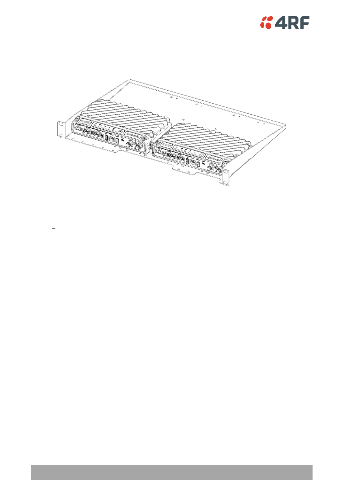
Rack Shelf Mounting
The Aprisa SR+ can be mounted on a rack mount shelf using the four M4 threaded holes in the Aprisa SR+
enclosure base. The following picture shows two Aprisa SR+ radios mounted on 1 RU rack mount shelf.

22 | Introduction
Aprisa SR+ Product Description
Wall Mounting
The Aprisa SR+ can be mounted on a wall using the two holes through the enclosure (5.2 mm diameter).
Typically, M5 screws longer than 35 mm would be used.

Product Options | 23
Aprisa SR+ Product Description
Interface Port Option
Part Number
4 Ethernet ports and no RS-232 serial ports
APSQ-N400-SSC-HD-40-ENAA
3 Ethernet ports and 1 RS-232 serial port
APSQ-N400-SSC-HD-31-ENAA
2 Ethernet ports and 2 RS-232 serial ports
APSQ-N400-SSC-HD-22-ENAA
2. Product Options
Interface Ports
The standard Aprisa SR+ provides multiple interface port options for combinations of Ethernet and RS-232
serial. The product shown below is the two Ethernet ports plus two RS-232 serial ports.

24 | Product Options
Aprisa SR+ Product Description
Part Number
Part Description
APSQ-R400-SSC-HD-22-ENAA
4RF SR+, PS, 400-470 MHz, SSC, Half Duplex, 2E2S, EN, AA
Protected Station
The Aprisa SR+ Protected Station is full monitored hot-standby and fully hot-swappable.
The Aprisa SR+ Protected Station provides radio and user interface protection for Aprisa SR+ radios when
configured as a base station. The RF ports and interface ports from the active Aprisa SR+ radio are
switched to the standby radio if there is a failure in the active radio.
Option Example
The Aprisa SR+ Protected Station is comprised of an Aprisa SR+ Protection Switch and two standard Aprisa
SR+ radios mounted in a 2U rack mounting chassis.
The Aprisa SR+ Protected Station is full monitored hot-standby and fully hot-swappable. All interfaces (RF,
data, etc.) are continually monitored on both the active and standby radio to ensure correct operation.
The standby radio can be replaced without impacting traffic flow on the active radio.
The Aprisa SR+ radios can be any of the currently available Aprisa SR+ radio frequency bands, channel
sizes or interface port options.
The Aprisa SR+ Protected Station can operate as a base station, repeater station or remote station. The
protection behaviour and switching criteria between the active and standby radios is identical for the
three configurations.
By default, the Aprisa SR+ Protected Station is configured with the left hand radio (A) designated as the
primary radio and the right hand radio (B) designated as the secondary radio.
Each radio is configured with its own unique IP and MAC address and the address of the partner radio.
On power-up, the primary radio will assume the active role and the secondary radio will assume the
standby role. If, for some reason, only one radio is powered on it will automatically assume the active
role.
Protected Ports
The protected ports are located on the protected station front panel. Switching occurs between the active
radio ports and the standby radio ports based on the switching criteria described below.
The protected ports include:
Antenna ports ANT/TX and RX (if dual antenna ports used)
Ethernet ports 1 and 2
Serial port

Product Options | 25
Aprisa SR+ Product Description
Operation
In hot-standby normal operation, the active radio carries all RS-232 serial and Ethernet traffic over the
radio link and the standby radio transmit is on with its transmitter connected to an internal load. Both
radios are continually monitored for correct operation including the transmitter and receiver and alarms
are raised if an event occurs.
The active radio sends regular ‘keep alive’ messages to the standby radio to indicate it is operating
correctly. In the event of a failure on the active radio, the RF link and user interface traffic is
automatically switched to the standby radio.
The failed radio can then be replaced in the field without interrupting user traffic (see Aprisa SR+ User
Manual).
Switch Over
The switch over to the standby radio can be initiated automatically, on fault detection, or manually via
the Hardware Manual Lock switch on the Protection Switch or the Software Manual Lock from SuperVisor.
Additionally, it is possible to switch over the radios remotely without visiting the station site, via the
remote control connector on the front of the Protection Switch.
Configuration Management
The Primary and Secondary radios are managed with the embedded web-based management tool,
SuperVisor, by using either the Primary or Secondary IP address. Configuration changes in one of the radios
will automatically be reflected in the partner radio.
To ensure all remote stations are registered to the correct (active) base station, changes to the Network
Table are automatically synchronized from the active radio to the standby radio. The Network Table is
only visible on the active radio. This synchronization does not occur if the Hardware Manual Lock is active.
26 | Product Options
Aprisa SR+ Product Description
Part Number
Part Description
APSQ-D400-SSC-HD-22-ENAA
4RF SR+, PD, 400-470 MHz, SSC, Half Duplex, 2E2S, EN, AA
Data Driven Protected Station
The Aprisa SR+ Data Driven Protected Station provides radio and RS-232 serial port user interface
protection for Aprisa SR+ radios.
Option Example
The Aprisa SR+ Data Driven Protected Station shown is comprised of two standard Aprisa SR+ dual antenna
port option radios and two external duplexers mounted on 19" rack mounting shelves (as shown above).
The Aprisa SR+ radios can be any of the currently available Aprisa SR+ radio frequency bands, channel
sizes or single / dual antenna port options.
By default, the Aprisa SR+ Data Driven Protected Station is configured with the left hand radio (A)
designated as the primary radio and the right hand radio (B) designated as the secondary radio.
Each radio is configured with its own unique IP and MAC address and the address of the partner radio.
On power-up, the primary radio will assume the active role and the secondary radio will assume the
standby role. If, for some reason, only one radio is powered on it will automatically assume the active
role.
Operation
In normal operation, the active radio carries all RS-232 serial and Ethernet traffic over the radio link and
the standby radio is unused with its transmitter turned off. Both radios are continually monitored for
correct operation and alarms are raised if an event occurs.
Both the active and standby radios send regular ‘keep alive’ messages to each other to indicate if they are
operating correctly. In the event of a failure on the active radio, the RF link and user interface traffic is
automatically switched to the standby radio.
The failed radio can then be replaced in the field without interrupting user traffic.

Product Options | 27
Aprisa SR+ Product Description
Part Number
Part Number
APSB-KDUP-300-A1
4RF SR+ Acc, Kit, Duplexer, 320-400 MHz, s 5 MHz, p 0.5 MHz, ext
APSB-KDUP-400-B1
4RF SR+ Acc, Kit, Duplexer, 400-470 MHz, s 5 MHz, p 0.5 MHz, ext
APSB-KDUP-450-M0
4RF SR+ Acc, Kit, Duplexer, 450-520 MHz, s 5 MHz, p 0.5 MHz, ext
APSB-KDUP-900-G2
4RF SR+ Acc, Kit, Duplexer, 928-960 MHz, s 9 MHz, p 1 MHz, ext
APSB-KDUP-900-G4
4RF SR+ Acc, Kit, Duplexer, 928-960 MHz, s 3.6 MHz, p 0.5 MHz, ext
Duplexer Kits
The Aprisa SR+ product range contains Duplexer Kit accessories for use with the Dual Antenna port Aprisa
SR+ radios.
UHF Duplexer Kits
The Aprisa SR+ UHF Duplexer Kit contains:
1x 1U 19" rack mount shelf with duplexer mounting brackets and screws
1x Duplexer
2x TNC to SMA right angle 590mm cables

28 | Product Options
Aprisa SR+ Product Description
Part Number
Part Number
APSB-KDUP-VHF-R2
4RF SR+ Acc, Kit, Duplexer, 152-175 MHz, s4-6 MHz, p100 kHz, High
APSB-KDUP-VHF-R3
4RF SR+ Acc, Kit, Duplexer, 152-175 MHz, s6-8 MHz, p100 kHz, High
APSB-KDUP-VHF-R4
4RF SR+ Acc, Kit, Duplexer, 152-175 MHz, s8-10 MHz, p100 kHz, High
APSB-KDUP-VHF-R5
4RF SR+ Acc, Kit, Duplexer, 138-156 MHz, s4-6 MHz, p100 kHz, Low
APSB-KDUP-VHF-R6
4RF SR+ Acc, Kit, Duplexer, 138-156 MHz, s6-8 MHz, p100 kHz, Low
APSB-KDUP-VHF-R7
4RF SR+ Acc, Kit, Duplexer, 138-156 MHz, s8-10 MHz, p100 kHz, Low
VHF Duplexer Kits
The Aprisa SR+ VHF Duplexer Kit contains:
1x 1U 19" rack mount shelf with duplexer mounting brackets and screws
1xVHF Procom Duplexer
1x VHF Filter, Procom BPF 2/3 HX-150, 145 to 174 MHz
1x N type male to N type male 325mm
2x TNC to N type male right angle 590mm cable

Product Options | 29
Aprisa SR+ Product Description
USB RS-232 Serial Port
The Aprisa SR+ USB host port is predominantly used for software upgrade and diagnostic reporting.
However, it can also be used to provide an additional RS-232 DCE serial port for customer traffic.
This is accomplished with a USB to RS-232 serial converter cable. This plugs into the USB host port
connector and can be terminated with the required customer connector.
This additional RS-232 serial port is enabled with the SuperVisor mode setting in Serial Port Settings.
The Aprisa SR+ USB port has driver support for these USB serial converters. Other USB serial converters
may not operate correctly.
USB RS-232 operation
The USB serial converter buffers the received data frames into 64 byte blocks separated by a small interframe gap.
For the majority of applications, this fragmentation of egress frames is not an issue. However, there are
some applications that may be sensitive to the inter-frame gap, therefore, these applications need
consideration.
A 5 ms inter-frame is recommended for the applications that are sensitive to inter-frame gap timings.
On a USB RS-232 port, Modbus RTU can operate up to 9600 bit/s with all packet sizes and up to 115200
bit/s if the packet size is less than 64 bytes. The standard RS-232 port is fully compatible with Modbus RTU
at all baud rates.

30 | Specifications
Aprisa SR+ Product Description
Broadcast Band
Frequency Band
Frequency Tuning
Range
Synthesizer Step
Size
UHF
320 MHz
320-400 MHz
6.250 kHz
Broadcast Band
Frequency Band
Frequency Tuning
Range
Synthesizer Step
Size
VHF
135 MHz
(1)
135-175 MHz
2.5 kHz
UHF
400 MHz
400-470 MHz
6.250 kHz
Broadcast Band
Frequency Band
Frequency Tuning
Range
Synthesizer Step
Size
UHF
450 MHz
(1)
450-520 MHz
6.250 kHz
Broadcast Band
Frequency Band
Frequency Tuning
Range
Synthesizer Step
Size
(1)
(1)
UHF
896 MHz
(1)
896-902 MHz
6.250 kHz
UHF
928 MHz
(1)
928-960 MHz
6.250 kHz
UHF
220 MHz
220-222 MHz
2.5 kHz
UHF
220 MHz
216-220 MHz
3.125 kHz
3. Specifications
RF Specifications
Blocking (desensitization), intermodulation, spurious response rejection, and adjacent channel selectivity
values determined according to the methods introduced in V1.7.1 of ETSI standards EN 300 113-1.
Frequency Bands
ETSI Compliant
ETSI / FCC / IC Compliant
ETSI / FCC Compliant
FCC / IC Compliant
Note 1: Please consult 4RF for availability.

Specifications | 31
Aprisa SR+ Product Description
Channel Size
Gross Radio Capacity
64 QAM
16 QAM
QPSK
4-CPFSK
12.5 kHz
60.0 kbit/s
40.0 kbit/s
20.0 kbit/s
9.6 kbit/s
25 kHz
120.0 kbit/s
80.0 kbit/s
40.0 kbit/s
19.2 kbit/s
Channel Size
Gross Radio Capacity less FEC
64 QAM
16 QAM
QPSK
4-CPFSK
12.5 kHz
52.0 kbit/s
23.1 kbit/s
11.6 kbit/s
8.4 kbit/s
25 kHz
103.9 kbit/s
46.2 kbit/s
23.1 kbit/s
16.7 kbit/s
Channel Size
Gross Radio Capacity less FEC
64 QAM
16 QAM
QPSK
4-CPFSK
12.5 kHz
45.6 kbit/s
17.3 kbit/s
8.7 kbit/s
4.1 kbit/s
25 kHz
91.2 kbit/s
34.6 kbit/s
17.3 kbit/s
8.3 kbit/s
Channel Sizes
ETSI Compliant
135 / 320 / 400 / 450 MHz Bands
No Forward Error Correction
Minimum Coded Forward Error Correction
Maximum Coded Forward Error Correction

32 | Specifications
Aprisa SR+ Product Description
Channel Size
Gross Radio Capacity
64 QAM
16 QAM
QPSK
4-CPFSK
12.5 kHz
54.0 kbit/s
36.0 kbit/s
18.0 kbit/s
9.6 kbit/s
25 kHz
96.0 kbit/s
64.0 kbit/s
32.0 kbit/s
19.2 kbit/s
Channel Size
Gross Radio Capacity less FEC
64 QAM
16 QAM
QPSK
4-CPFSK
12.5 kHz
46.8 kbit/s
20.8 kbit/s
10.4 kbit/s
8.4 kbit/s
25 kHz
83.1 kbit/s
37.0 kbit/s
18.5 kbit/s
16.7 kbit/s
Channel Size
Gross Radio Capacity less FEC
64 QAM
16 QAM
QPSK
4-CPFSK
12.5 kHz
41.0 kbit/s
15.6 kbit/s
7.8 kbit/s
4.1 kbit/s
25 kHz
73.0 kbit/s
27.7 kbit/s
13.9 kbit/s
8.3 kbit/s
FCC / IC Compliant
135 / 400 / 450 MHz Bands
No Forward Error Correction
Minimum Coded Forward Error Correction
Maximum Coded Forward Error Correction

Specifications | 33
Aprisa SR+ Product Description
Channel Size
Gross Radio Capacity
64 QAM
16 QAM
QPSK
4-CPFSK
12.5 kHz
60.0 kbit/s
40.0 kbit/s
20.0 kbit/s
9.6 kbit/s
25 kHz
96.0 kbit/s
64.0 kbit/s
32.0 kbit/s
19.2 kbit/s
50 kHz
216.0 kbit/s
144.0 kbit/s
72.0 kbit/s
38.4 kbit/s
Channel Size
Gross Radio Capacity less FEC
64 QAM
16 QAM
QPSK
4-CPFSK
12.5 kHz
52.0 kbit/s
23.1 kbit/s
11.6 kbit/s
8.4 kbit/s
25 kHz
83.1 kbit/s
37.0 kbit/s
18.5 kbit/s
16.7 kbit/s
50 kHz
187.1 kbit/s
83.2 kbit/s
41.6 kbit/s
33.4 kbit/s
Channel Size
Gross Radio Capacity less FEC
64 QAM
16 QAM
QPSK
4-CPFSK
12.5 kHz
45.6 kbit/s
17.3 kbit/s
8.7 kbit/s
4.1 kbit/s
25 kHz
73.0 kbit/s
27.7 kbit/s
13.9 kbit/s
8.3 kbit/s
50 kHz
164.2 kbit/s
62.4 kbit/s
31.2 kbit/s
16.5 kbit/s
220 / 896 / 928 MHz Bands
No Forward Error Correction
Minimum Coded Forward Error Correction
Maximum Coded Forward Error Correction

34 | Specifications
Aprisa SR+ Product Description
12.5 kHz
25 kHz
50 kHz
FCC / IC only
BER < 10-2
64 QAM
Max coded FEC
-106 dBm
-102 dBm
-99 dBm
BER < 10-2
64 QAM
Min coded FEC
-105 dBm
-101 dBm
-98 dBm
BER < 10-2
64 QAM
No FEC
-103 dBm
-99 dBm
-96 dBm
BER < 10-2
16 QAM
Max coded FEC
-113 dBm
-110 dBm
-107 dBm
BER < 10-2
16 QAM
Min coded FEC
-112 dBm
-109 dBm
-106 dBm
BER < 10-2
16 QAM
No FEC
-109 dBm
-106 dBm
-103 dBm
BER < 10-2
QPSK
Max coded FEC
-118 dBm
-115 dBm
-112 dBm
BER < 10-2
QPSK
Min coded FEC
-117 dBm
-114 dBm
-111 dBm
BER < 10-2
QPSK
No FEC
-115 dBm
-112 dBm
-109 dBm
BER < 10-2
4-CPFSK
Max coded FEC
NA
NA
NA
BER < 10-2
4-CPFSK
Min coded FEC
-117 dBm
-114 dBm
-111 dBm
BER < 10-2
4-CPFSK
No FEC
-115 dBm
-112 dBm
-109 dBm
BER < 10-6
64 QAM
Max coded FEC
-103 dBm
-99 dBm
-96 dBm
BER < 10-6
64 QAM
Min coded FEC
-101 dBm
-97 dBm
-94 dBm
BER < 10-6
64 QAM
No FEC
-96 dBm
-92 dBm
-89 dBm
BER < 10-6
16 QAM
Max coded FEC
-110 dBm
-107 dBm
-104 dBm
BER < 10-6
16 QAM
Min coded FEC
-108 dBm
-105 dBm
-102 dBm
BER < 10-6
16 QAM
No FEC
-102 dBm
-99 dBm
-96 dBm
BER < 10-6
QPSK
Max coded FEC
-115 dBm
-112 dBm
-109 dBm
BER < 10-6
QPSK
Min coded FEC
-113 dBm
-110 dBm
-107 dBm
BER < 10-6
QPSK
No FEC
-108 dBm
-105 dBm
-102 dBm
BER < 10-6
4-CPFSK
Max coded FEC
NA
NA
NA
BER < 10-6
4-CPFSK
Min coded FEC
-113 dBm
-110 dBm
-107 dBm
BER < 10-6
4-CPFSK
No FEC
-108 dBm
-105 dBm
-102 dBm
Receiver
ETSI / FCC / IC Compliant Receiver Sensitivity

Specifications | 35
Aprisa SR+ Product Description
12.5 kHz
25 kHz
50 kHz
FCC / IC only
Adjacent channel selectivity
> -47 dBm
> -37 dBm
> -37 dBm
BER < 10-2
64 QAM
> 43 dB
> 53 dB
> 53 dB
BER < 10-2
16 QAM
> 43 dB
> 53 dB
> 53 dB
BER < 10-2
QPFK
> 48 dB
> 58 dB
> 58 dB
BER < 10-2
4-CPFSK
> 55 dB
> 65 dB
> 65 dB
12.5 kHz
25 kHz
50 kHz
FCC / IC only
BER < 10-2
64 QAM
> –23 dB
> –23 dB
> –23 dB
BER < 10-2
16 QAM
> –19 dB
> –19 dB
> –19 dB
BER < 10-2
QPFK
> –12 dB
> –12 dB
> –12 dB
BER < 10-2
4-CPFSK
> –17 dB
> –17 dB
> –17 dB
12.5 kHz
25 kHz
50 kHz
FCC / IC only
Intermodulation response rejection
> -35 dBm
> -35 dBm
> -35 dBm
BER < 10-2
64 QAM
> 55 dB
> 55 dB
> 55 dB
BER < 10-2
16 QAM
> 55 dB
> 55 dB
> 55 dB
BER < 10-2
QPFK
> 60 dB
> 60 dB
> 60 dB
BER < 10-2
4-CPFSK
> 65 dB
> 65 dB
> 65 dB
12.5 kHz
25 kHz
50 kHz
FCC / IC only
Blocking or desensitization
> -17 dBm
> -17 dBm
> -17 dBm
BER < 10-2
64 QAM
> 73 dB
> 73 dB
> 73 dB
BER < 10-2
16 QAM
> 73 dB
> 73 dB
> 73 dB
BER < 10-2
QPFK
> 78 dB
> 78 dB
> 78 dB
BER < 10-2
4-CPFSK
> 85 dB
> 85 dB
> 85 dB
ETSI / FCC / IC Compliant Adjacent Channel Selectivity
ETSI / FCC / IC Compliant Co-Channel Rejection
ETSI / FCC / IC Compliant Intermodulation Response Rejection
ETSI / FCC / IC Compliant Blocking or Desensitization

36 | Specifications
Aprisa SR+ Product Description
12.5 kHz
25 kHz
50 kHz
FCC / IC only
Spurious response rejection
> -32 dBm
> -32 dBm
> -32 dBm
BER < 10-2
64 QAM
> 58 dB
> 58 dB
> 58 dB
BER < 10-2
16 QAM
> 58 dB
> 58 dB
> 58 dB
BER < 10-2
QPFK
> 63 dB
> 63 dB
> 63 dB
BER < 10-2
4-CPFSK
> 70 dB
> 70 dB
> 70 dB
12.5 kHz
25 kHz
50 kHz
FCC / IC only
Receiver spurious radiation
> -57 dBm
> -57 dBm
> -57 dBm
ETSI / FCC / IC Compliant Spurious Response Rejection
ETSI / FCC / IC Compliant Receiver Spurious Radiation

Specifications | 37
Aprisa SR+ Product Description
Average Power output
64 QAM
0.01 to 2.5 W (+10 to +34 dBm, in 1 dB steps)
Note: The Peak Envelope Power
(PEP) at maximum set power
level is +41 dBm.
16 QAM
0.01 to 3.2 W (+10 to +35 dBm, in 1 dB steps)
QPSK
0.01 to 5.0 W (+10 to +37 dBm, in 1 dB steps)
4-CPFSK
(Note 1)
0.01 to 10.0 W (+10 to +40 dBm, in 1 dB steps)
Adjacent channel power
< - 60 dBc
Transient adjacent channel power
< - 60 dBc
Spurious emissions
< - 37 dBm
Attack time
< 1.5 ms
Release time
< 0.5 ms
Data turnaround time
< 2 ms
Frequency stability
± 1.0 ppm
± 0.1 ppm
The 220 / 896 / 928 MHz products have a
frequency stability option of ± 0.1 ppm.
Frequency aging
< 1 ppm / annum
Forward Error Correction
Variable length concatenated Reed Solomon
plus convolutional code
Adaptive Burst Support
Adaptive FEC
Adaptive Coding Modulation
Data payload security
CCM* Counter with CBC-MAC
Data encryption
Counter Mode Encryption (CTR) using Advanced
Encryption Standard (AES) 128, 192 or 256
Data authentication
Cipher Block Chaining Message Authentication
Code (CBC-MAC) using Advanced Encryption
Standard (AES) 128, 192 or 256
Transmitter
Note 1: Please consult 4RF for availability
Note: The Aprisa SR+ transmitter contains power amplifier protection which allows the antenna to be
disconnected from the antenna port without product damage.
Modem
Data Payload Security

38 | Specifications
Aprisa SR+ Product Description
General
Interface
RJ45 x 2 (Integrated 2-port switch)
Cabling
CAT-5/6 UTP, supports auto MDIX (Standard Ethernet)
Maximum line length
100 metres on cat-5 or better
Bandwidth allocation
The Ethernet capacity maximum is determined by the
available radio link capacity.
Maximum transmission unit
Option setting of 1522 or 1536 octets
Address table size
1024 MAC addresses
Ethernet mode
10Base-T or 100Base-TX
Full duplex or half duplex
(Auto-negotiating and auto-sensing)
Diagnostics
Left Green LED
Off: no Ethernet signal received
On: Ethernet signal received
Right Orange LED
Off: no data present on the interface
Flashing: data present on the interface
Interface Specifications
Ethernet Interface
The Aprisa SR+ radio features an integrated 10Base-T/100Base-TX layer-2 Ethernet switch.
To simplify network setup, each port supports auto-negotiation and auto-sensing MDI/MDIX. Operators can
select from the following preset modes:
Auto negotiate
10Base-T half or full duplex
100Base-TX half or full duplex
The Ethernet ports are IEEE 802.3-compatible. The L2 Bridge (Switch) is IEEE 802.1d/q/p compatible, and
supports VLANs and VLAN manipulation of add/remove VLANs.
Note: Do not connect Power over Ethernet (PoE) connections to the Aprisa SR+ Ethernet ports as this will
damage the port.

Specifications | 39
Aprisa SR+ Product Description
General
Interface
ITU-T V.24 / EIA/TIA RS-232E
Interface direction
DCE only
Maximum line length
10 metres (dependent on baud rate)
Async
parameters
Standard mode data bits
7 or 8 bits
Standard mode parity
Configurable for None, Even or Odd
Standard mode stop bits
1 or 2 bits
Interface baud rates
300, 1200, 2400, 4800, 9600, 19200, 38400, 57600 and
115200 bit/s
Control signals
DCE to DTE
CTS, RTS, DSR, DTR
Diagnostics
Left Green LED
Off: no RS-232 device connected
On: RS-232 device connected
Right Orange LED
Off: no data present on the interface
Flashing: data present on the interface
RS-232 Asynchronous Interface
The Aprisa SR+ radio’s ITU-T V.24 compliant RS-232 interface is configured as a Cisco® pinout DCE. The
interface terminates to a DTE using a straight-through cable or to a DCE with a crossover cable (null
modem).
The interface uses two handshaking control lines between the DTE and the DCE.

40 | Specifications
Aprisa SR+ Product Description
Interface
RJ45 connector
Detector type
Non-isolated ground referenced voltage
detector
Detection voltage - on
> +10 VDC
Detection voltage - off
< +4 VDC
Maximum applied input voltage
30 VDC
Maximum input current limit
10 mA
Interface
RJ45 connector
Output type
Non-isolated ground referenced open
collector output
Maximum applied voltage
30 VDC
Maximum drive current
100 mA
Overload protection
Thermally resettable fuse
Interface
Female protect connector
RF Insertion Loss
< 0.5 dB
Remote Control inputs
Logic 4700 ohms pullup to +3.3 VDC
Hardware Alarms Interface
The hardware alarms interface supports two alarm inputs and two alarms outputs.
Alarm Inputs
The alarm connector provides two hardware alarm inputs for alarm transmission to the other radios in the
network.
Alarm Outputs
The alarm connector provides two hardware alarm outputs for alarm reception from other radios in the
network.
Protect Interface
The Protect interface is used to connect the radios to the protection switch within a Protected Station. It
is not a customer interface.
Protection Switch Specifications

Specifications | 41
Aprisa SR+ Product Description
Nominal voltage
+13.8 VDC (negative earth)
Absolute input voltage range
+10 to +30 VDC
Maximum power input
35 W
Connector
Molex 2 pin male screw fitting
39526-4002
Nominal voltage
+13.8 VDC (negative earth)
Absolute input voltage range
+10 to +30 VDC
Maximum power input
35 W
Connector
2x Molex 2 pin male screw fitting
39526-4002
Nominal voltage
+13.8 VDC (negative earth)
Absolute input voltage range
+10 to +30 VDC
Maximum power input
35 W
Connector
2x Molex 2 pin male screw fitting
39526-4002
Power Specifications
Power Supply
Aprisa SR+ Radio
Aprisa SR+ Protected Station
Aprisa SR+ Data Driven Protected Station
42 | Specifications
Aprisa SR+ Product Description
Mode
Power Consumption
(10 W radio with 4-CPFSK modulation)
Transmit / Receive
< 35 W for 10 W transmit power
< 25.0 W for 1 W transmit power
Receive only
< 7 W
Mode
Power Consumption
(10 W radios with 4-CPFSK modulation)
Transmit / Receive
< 42 W for 10 W transmit power
< 32.0 W for 1 W transmit power
Receive only
< 15 W
Transmit Power
Power Dissipation
(10 W radio with 4-CPFSK modulation)
10 W transmit power
< 25 W
1 W transmit power
< 24 W
Transmit Power
Power Dissipation
(10 W radios with 4-CPFSK modulation)
10 W transmit power
< 32 W
1 W transmit power
< 31 W
Power Consumption
Note: The radio power consumption is very dependent on transmitter power, the type of traffic and
network activity.
Aprisa SR+ Radio
Aprisa SR+ Protected Station and Aprisa SR+ Data Driven Protected Station
Power Dissipation
Aprisa SR+ Radio
Aprisa SR+ Protected Station and Aprisa SR+ Data Driven Protected Station
Specifications | 43
Aprisa SR+ Product Description
Operating temperature range
-40 to +70˚ C (-40 to +158˚ F)
Storage temperature range
-40 to +80˚ C (-40 to +176˚ F)
Operating humidity
Maximum 95% non-condensing
Acoustic noise emission
No audible noise emission
Dimensions
Width 210 mm (8.27”)
Depth 130 mm (5.12”) and 146 mm (5.748”)
with TNC connectors
Height 41.5 mm (1.63”)
Weight
1.25 kg (2.81 lbs)
Colour
Matt black
Mounting
Wall (2 x M5 screws)
Rack shelf (2 x M4 screws)
DIN rail bracket
Dimensions
Width 432.6 mm (17”)
Depth 372 mm (14.6”) and 388 mm (15.276”)
with TNC connectors
Height 2U plus external duplexer (if used)
Weight
12 kg (27 lbs) (includes the 2 radios)
Colour
Matt black
Mounting
Rack mount (2 x M6 screws)
General Specifications
Environmental
Mechanical
Aprisa SR+ Radio
Aprisa SR+ Protected Station

44 | Specifications
Aprisa SR+ Product Description
Radio
EN 300 113-2
EMI / EMC
EN 301 489 Parts 1 & 5
Safety
EN 60950-1:2006
Class 1 div 2 for hazardous locations
Environmental
ETS 300 019 Class 3.4
Ingress Protection code IP51
Radio
47CFR part 24, part 90 and part 101 Private
Land Mobile Radio Services
EMC
47CFR part 15 Radio Frequency Devices, EN
301 489 Parts 1 & 4
Safety
EN 60950-1:2006
Class 1 div 2 for hazardous locations
Environmental
ETS 300 019 Class 3.4
Ingress Protection code IP51
Radio
RSS-119 / RSS-134
EMC
This Class A digital apparatus complies with
Canadian standard ICES-003.
Cet appareil numérique de la classe A est
conforme à la norme NMB-003 du Canada.
Safety
EN 60950-1:2006
Class 1 div 2 for hazardous locations
Environmental
ETS 300 019 Class 3.4
Ingress Protection code IP51
Compliance
ETSI
FCC
IC

Management | 45
Aprisa SR+ Product Description
4. Management
SuperVisor
The Aprisa SR+ contains an embedded web server application (SuperVisor) to enable element management
with any major web browser (such as Mozilla Firefox or Microsoft® Internet Explorer).
SuperVisor enables operators to configure and manage the Aprisa SR+ base station radio and repeater /
remote station radios over the radio link.
The key features of SuperVisor are:
Full element management, configuration and diagnostics
Manage the entire network from the Base Station (remote management of elements)
Managed network software distribution and upgrades
Performance and alarm monitoring of the entire network, including RSSI, alarm states, time-
stamped events.
View and set standard radio configuration parameters including frequencies, transmit power,
channel access, serial, Ethernet port settings
Set and view security parameters
User management
Operates over a secure HTTPS session on the access connection to the base station
The following are three examples of SuperVisor screens:
46 | Management
Aprisa SR+ Product Description
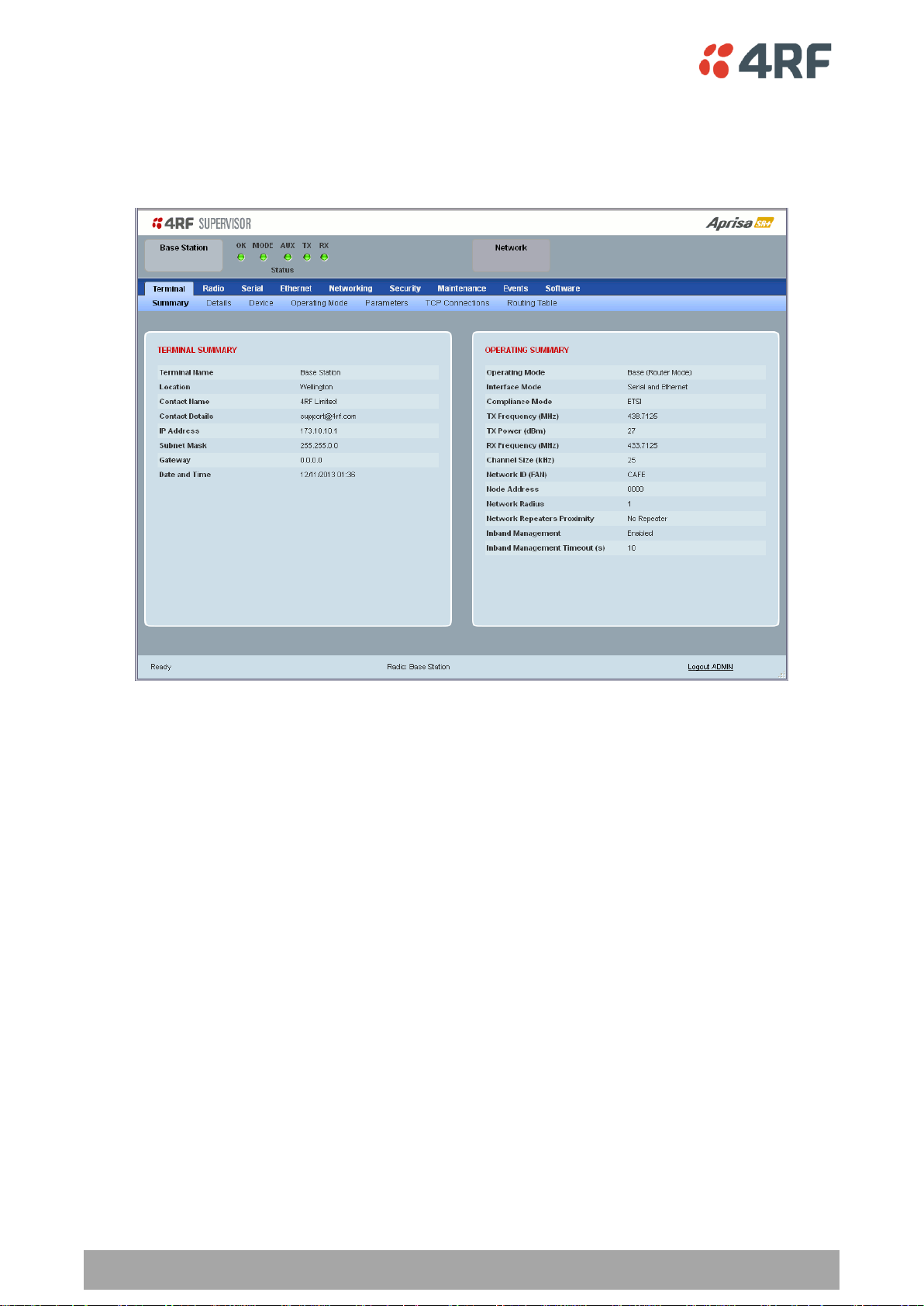
Viewing the Aprisa SR+ Terminal Settings
The SuperVisor software enables operators to view the terminal settings:

Management | 47
Aprisa SR+ Product Description
Network ID
Sets the network ID of this base station node and its remote
nodes.
Four hex chars
Network Radius
Sets the maximum number of hops in this network
Network Repeaters
Proximity
Sets the proximity of repeaters in this network
Inband Management
Enables inband management of remotes / repeaters
Inband Management
Timeout (sec)
Sets the inband management timeout period
Configuring the Aprisa SR+ Terminal Details
The SuperVisor software enables operators to set the terminal details including Terminal Name, Location,
Contact Name and Contact Details with a maximum of 40 characters.
Configuring the Aprisa SR+ RF Network Details
The SuperVisor software enables operators to set the RF Network Details including:

48 | Management
Aprisa SR+ Product Description
TX Frequency
Sets the transmit frequency in MHz
TX Power
Sets the transmit Power in dBm
RX Frequency
Sets the receive frequency in MHz
Channel Size
Sets the channel size 12.5 kHz, 25 kHz or 50 kHz (depending
on variant)
Antenna Port Configuration
Sets the antenna port configuration to single port or dual
port
Modulation Type
Sets the fixed TX Modulation Type for the base station radio
ACM Control
Enables / disables Adaptive Code Modulation for the remote
to base direction of transmission (upstream)
Modulation Range
Sets the upper limit of the range that the base station willl
recommmend to the remote radios
Configuring the Aprisa SR+ Radio Settings
The SuperVisor software enables operators to set the radio settings including:

Management | 49
Aprisa SR+ Product Description
Command Line Interface
The Aprisa SR+ has a Command Line Interface (CLI) which provides basic product setup and configuration.
This interface can be accessed via an Ethernet Port (RJ45) or the Management Port (USB micro type B).
The Terminal menu is shown in the following picture:
SNMP
In addition to web-based management (SuperVisor) and the Command Line Interface, the Aprisa SR
network can also be managed using the Simple Network Management Protocol (SNMP agent). MIB files are
supplied which can be used by a dedicated SNMP Manager, such as Castle Rock’s network management
system, to support effective and flexible network monitoring and diagnostics.
Alternatively, the user can use its own 3rd party NMS SNMP agent to manage the SR+ radio network.
For communication between the SNMP manager and the radio, Access Controls and Community strings
must be set up as described in the Aprisa SR+ User Manual.

50 | Management
Aprisa SR+ Product Description
OK
MODE
AUX
TX
RX
Solid
Red
Alarm present
with severity
Critical, Major
and Minor
TX path fail
RX path fail
Flashing
Red
Radio not
connected to a
base station
Radio not
connected to a
base station
Solid
Orange
Alarm present
with Warning
Severity
Stand-by radio
in protected
station
Device detect
on the USB
host port
(single flash)
Flashing
Orange
Diagnostics
Function
Active
OTA Firmware
Distribution
Tx Data or Rx
Data on the
USB
management
or host port
Flashing
Green
RF path TX is
active
RF path RX is
active
Solid
Green
Power on and
functions OK
and no alarms
Processor
Block is OK
or active radio
in protected
station
USB interface
OK
Tx path OK
Rx path OK
LED Colour
Severity
Green
No alarm – information only
Orange
Warning alarm
Red
Critical, major or minor alarm
LED Display Panel
The Aprisa SR+ has an LED Display panel which provides on-site alarms / diagnostics without the need for
PC.
Normal Operation
In normal radio operation, the LEDs indicate the following conditions:

Management | 51
Aprisa SR+ Product Description
Single Radio Software Upgrade
During a radio software upgrade, the LEDs indicate the following conditions:
Software upgrade started - the OK LED flashes orange
Software upgrade progress indicated by running RX to OK LEDs
Software upgrade completed successfully - the OK LED solid orange
Software upgrade failed - any LED flashing red during the upgrade
Network Software Upgrade
During a network software upgrade, the MODE LED flashes orange on the base station and all remote
stations.
Test Mode
In Test Mode, the LED Display panel presents a real time visual display of the RSSI. This can be used to
adjust the antenna for optimum signal strength.
52 | Applications
Aprisa SR+ Product Description
5. Applications
This section describes sample Aprisa SR+ radio applications.
The following applications are described:
Basic point-to-multipoint application
Advanced point-to-multipoint application with repeaters
Multi-interface point-to-multipoint application
Multi-hop Daisy chain repeaters in LBS mode application
Pseudo Peer to Peer using base-repeater application
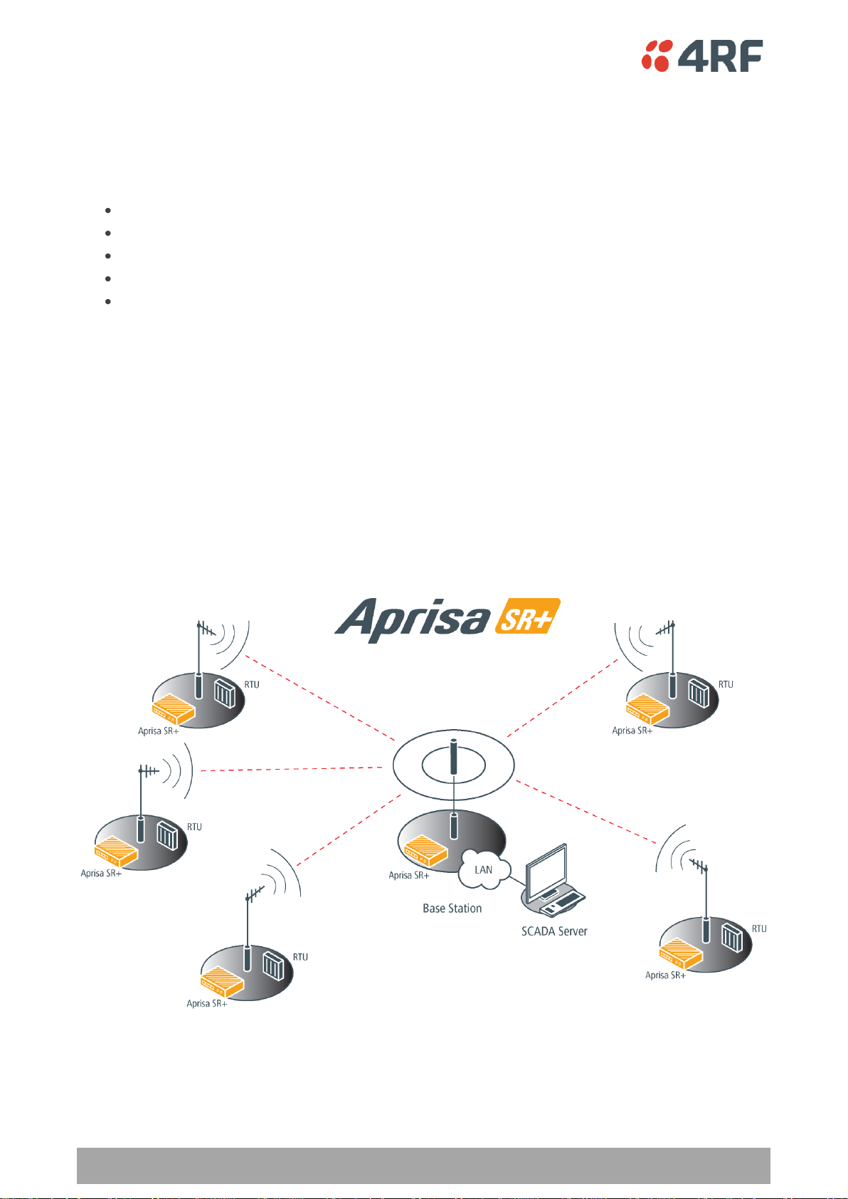
Basic point-to-multipoint application
Single base station with Ethernet SCADA data inputs to multiple geographically remote sites with Ethernet
RTUs requiring control and data acquisition.
The base station receives Ethernet frames from the SCADA server LAN and broadcasts all Ethernet frames
to all remote stations
Each remote site receives Ethernet frames from the RTU and unicasts over the air to the base station.
The base station uses an omni directional antenna to provide wide coverage and the remote stations are
fitted with directional Yagi antennas to provide higher gain.

Applications | 53
Aprisa SR+ Product Description
Advanced point-to-multipoint application with repeater
Single base station with Ethernet SCADA data inputs to multiple geographically remote sites with Ethernet
RTUs requiring control and data acquisition. A repeater is deployed to service remote sites beyond the
reach of the base station.
The base station receives Ethernet frames from the SCADA server LAN and broadcasts all Ethernet frames
to the repeater and its remote stations.
Three remote sites have direct radio communication with the base station but the other two remote sites
operate via the repeater site.
Each remote site receives Ethernet frames from the RTU and unicasts over the air to the repeater / base
station.
The base station and the repeater station use an omni directional antenna to provide wide coverage and
the remote stations are fitted with directional Yagi antennas to provide higher gain.

54 | Applications
Aprisa SR+ Product Description
Multi-interface point-to-multipoint application
Single base station with Ethernet and RS-232 SCADA data inputs to multiple geographically remote sites
with Ethernet and RS-232 RTUs requiring control and data acquisition.
The base station receives Ethernet / RS-232 frames from the SCADA servers and broadcasts all frames to
all remote stations
Each remote site receives Ethernet / RS-232 frames from the RTU and unicasts over the air to the base
station.
The base station uses an omni directional antenna to provide wide coverage and the remote stations are
fitted with directional Yagi antennas to provide higher gain.

Applications | 55
Aprisa SR+ Product Description
Multi-hop Daisy Chain Repeaters in LBS Mode Application
This application is used for daisy chain repeaters when remote stations are very far from base station
coverage. Daisy chain repeaters can only be used in LBS channel access mode (and future release in AR
mode).
In the figure example below, the Base Station can communicate with any of the far remotes via the daisy
chain repeaters. The SCADA master will communicate with RTU 2 using a source and destination IP address
and the underlining SCADA protocol.
On the downstream, the SCADA master would like to communicate with RTU-2 and sends a packet
destined to RTU-2 (using RTU 2 destination address). This packet received by the Base Station will then
broadcast OTA to Repeater 1.
Repeater 1 will store-and-forward the received packet and re-transmit the packet to Repeater 2 and back
to the Base Station, which will drop the duplicate packet as this packet is its own forward.
Repeater 2 will store-and-forward the packet to the local Ethernet port to RTU 3 (which will drop the
packet due to destination address mismatch) and it will also re-transmit the packet OTA to Repeater 3,
Remote 1 and back to Repeater 1, which will drop the duplicate packet as this packet is its own forward.
Remote-1 will forward the packet to its local Ethernet port and RTU-1 will drop the packet due to
destination address mismatch.
Repeater 3 will store-and-forward and re-transmit the packet OTA to Remote-2 and back to Repeater 2,
which will drop the packet as duplicate packet as this packet is its own forward.
Remote 2 will then forward the packet to its local Ethernet port and RTU 2 as the destined address which
will process the packet accordingly.
On the upstream, RTU 2 will send a packet to the SCADA master, and the radio network from Remote 2
sending a unicast packet destined to Base Station which will act with the same process mechanism as
described above for downstream path.

56 | Applications
Aprisa SR+ Product Description
Pseudo Peer to Peer using Base-Repeater Application
This application is used for remote peer to peer communication via a base-repeater or repeater
configuration. In peer to peer, the source RTU will create a message with destination address of the
destined RTU in the SCADA layer protocol (and/or IP layer, if applicable). Note, this address is only known
by the RTUs as the SR+ radio is transparent to SCADA protocol messages. Although all messages sent from
remotes are always destined to the base station, packets can be sent from one remote to the other using
the ‘packet filtering’ peer to peer feature (see the Aprisa SR+ User Manual Radio > Channel Setup) and
base-repeater or repeater configuration.
In the figure example below, RTU 1 would like to communicate with RTU 3, and thus, Remote 1 and
Remote 3 will be configured with ‘packet filtering’ set to ‘disabled’ and the Base station configured as a
Base-repeater.
RTU 1 will create a message destined to RTU 3 and forward it to Remote 1, which in turn will forward it as
a unicast message OTA to the Repeater Station, destined to the Base Station (all packets from a remote
are destined to the base station).
The Repeater Station will store-and-forward the message received from Remote 1 and re-transmit the
message to Base Station, but it will also be received by Remote 2. Since, Remote 2 is not the destination
and packet filtering is set to automatic (enabled), the packet will be dropped by Remote 2. Note, Remote
3 and Remote 4 can’t hear the Repeater Station.
The Base-Repeater will forward the packet to the local ports (Ethernet and/or serial), and will also retransmit the packet OTA to Remote 3 and Remote 4 and back to the Repeater (this is specific and default
to Base-Repeater functionality, as packet filtering is not used in Base-Repeater operation and it can be
left in default (automatic)). The Repeater will drop the duplicate packet as this packet is its own forward.
Remote 3 will receive the packet and forward it to it local ports (Ethernet or Serial) and to its local RTU 3,
as packet filtering is disabled which will then process the packet accordingly. Remote 4 will also receive
the packet, but it will drop the packet as packet filtering is enabled. If Remote 4 had packet filtering
disabled, the packet would be forwarded to the local port and dropped by RTU 4, due to SCADA protocol
destination address mismatch (and/or IP destination address mismatch, if applicable).

Product Architecture | 57
Aprisa SR+ Product Description
Option
Function
Access Request
Channel access scheme where the base stations controls the
communication on the channel. Remotes ask for access to the
channel, and the base station grants access if the channel is not
occupied.
Listen Before Send
Channel access scheme where network elements listen to ensure
the channel is clear, before trying to access the channel.
6. Product Architecture
Product Operation
There are three components to the wireless interface: the Physical Layer (PHY), the Data Link Layer (DLL)
and the Network Layer. These three layers are required to transport data across the wireless channel in
the Point-to-multipoint (PMP) configuration. The Aprisa SR+ DLL is largely based on the 802.15.4 MAC layer
using a proprietary implementation.
Physical Layer
The Aprisa SR+ PHY uses a one or two frequency half duplex transmission mode which eliminates the need
for a duplexer. However, a Dual Antenna port option is available for separate transmit and receive
antenna connection to support external duplexers or filters (half duplex operation).
Remote nodes are predominantly in receive mode with only sporadic bursts of transmit data. This reduces
power consumption.
The Aprisa SR+ is a packet based radio. Data is sent over the wireless channel in discrete packets /
frames, separated in time. The PHY demodulates data within these packets with coherent detection.
The Aprisa SR+ PHY provides carrier, symbol and frame synchronization predominantly through the use of
preambles. This preamble prefixes all packets sent over the wireless channel which enables fast
Synchronization.
Data Link Layer / MAC layer
The Aprisa SR+ PHY enables multiple users to be able to share a single wireless channel; however a DLL is
required to manage data transport. The two key components to the DLL are channel access and hop by
hop transmission.
Channel Access
The Aprisa SR+ radio has two modes of channel access, Access Request and Listen Before Send.

58 | Product Architecture
Aprisa SR+ Product Description
Access Request
This scheme is particularly suited to digital SCADA systems where all data flows through the base station.
In this case it is important that the base station has contention-free access as it is involved in every
transaction. The channel access scheme assigns the base station as the channel access arbitrator and
therefore inherently it has contention-free access to the channel. This means that there is no possibility
of contention on data originating from the base station. As all data flows to or from the base station, this
significantly improves the robustness of the system.
All data messages are controlled via the AG (access grant) control message and therefore there is no
possibility of contention on the actual end user data. If a remote station accesses the channel, the only
contention risk is on the AR (access request) control message. These control messages are designed to be
as short as possible and therefore the risk of collision of these control messages is significantly reduced.
Should collisions occur these are resolved using a random back off and retry mechanism.
As the base station controls all data transactions multiple applications can be effectively handled,
including a mixture of polling and report by exception.
Listen Before Send
The Listen Before Send channel access scheme is realized using Carrier Sense Multiple Access (CSMA). In
this mode, a pending transmission requires the channel to be clear. This is determined by monitoring the
channel for other signals for a set time prior to transmission. This results in reduced collisions and
improved channel capacity.
There are still possibilities for collisions with this technique e.g. if two radios simultaneously determine
the channel is clear and transmit at the same time. In this case an acknowledged transaction may be used.
The transmitter requests an ACK to ensure that the transmission has been successful. If the transmitter
does not receive an ACK, then random backoffs are used to reschedule the next transmission.
Hop by Hop Transmission
Hop by Hop Transmission is realized in the Aprisa SR+ by adding a MAC address header to the packet. For
802.15.4, there are 2 addresses, the source and destination addresses.

Product Architecture | 59
Aprisa SR+ Product Description
Adaptive Coding Modulation
The Aprisa SR+ provides Adaptive Coding Modulation (ACM) which maximizes the use of the RF path to
provide the highest radio capacity available.
ACM automatically adjusts the modulation coding and FEC code rate in the remote to base direction of
transmission over the defined modulation range based on the signal quality for each individual remote
radio.
When the RF path is healthy (no fading), modulation coding is increased and the FEC code rate is
decreased to maximize the data capacity.
If the RF path quality degrades, modulation coding is decreased and the FEC code rate is increased for
maximum robustness to maintain path connectivity.

60 | Product Architecture
Aprisa SR+ Product Description
Network Layer
Packet Routing
Aprisa SR+ is a standard static IP router which routes and forwards IP packet based on standard IP address
and routing table decisions.
Aprisa SR+ router mode (see figure below), enables the routing of IP packets within the Aprisa SR+ wireless
network and in and out to the external router / IP RTUs devices connected to the Aprisa SR+ wired
Ethernet ports.
Within the Aprisa SR+ Router mode, each incoming Ethernet packet on the Ethernet port is stripped from
its Ethernet header to reveal the IP packet and to route the IP packet based on its routing table. If the
destination IP address is one of the RTUs, the packet is then forwarded to the wireless ports and
broadcasted as a PMP wireless packet to all the repeater / remotes stations. The appropriate remote then
routes the IP packet and forwards it based on its routing table to the appropriate Ethernet port,
encapsulating the appropriate next hop MAC header and forwarding it to the RTU. The RTU can then
interpret and process the IP data and communication is established between the RTU and the initiating
communication device.

Product Architecture | 61
Aprisa SR+ Product Description
Static IP Router
The Aprisa SR+ works in the point-to-multipoint (PMP) network as a standard static IP router with the
Ethernet and wireless / radio as interfaces and serial ports using terminal server as a virtual interface.
The Aprisa SR+ static router is semi-automated operation, where the routing table is automatically
created in the base station and populated with routes to all remotes and repeater stations in the network
during the registration process and vice versa, where the routing table is automatically created in remote
and repeater stations and populated with routes to base station during the registration process. Updates
occur when remote is disconnected from network for any reason, with the routing table updated in a
controlled fashion.
Also, in decommission operation, the base station routing tables are completely flushed allowing an
automatic rebuild. This avoids the user manually inserting / removing of multiple static routes to build /
change the routes in the network which might be tedious and introduce significant human error. The
Aprisa SR+ works as a static IP router without using any routing protocol and therefore does not have the
overhead of a routing protocol for better utilization of the narrow bandwidth network.
In addition to the semi-automated routes, the user can manually add / remove routes in the routing table
for the radio interface, Ethernet Interface and for routers which are connected to the radio network.
The Aprisa SR+ base station is used as a gateway to other networks. Thus, a configurable IP address
default gateway can be set using a static route in the routing table with a destination IP address of
0.0.0.0. It is used by the router when an IP address does not match any other routes in the routing table.
The Aprisa SR+ sub-netting rules distinguish between the wireless interface and the remote Ethernet
interface where RTUs are connected. The entire wireless network is set on a single IP subnet, while each
Aprisa SR+ remote’s Ethernet interface is set to a different subnet network. In this way, the user can
easily distinguish between the remotes subnet IP addresses.

62 | Product Architecture
Aprisa SR+ Product Description
Static IP Router – Human Error Free
To ensure correct operation, the Aprisa SR+ router base station alerts when one (or more) of the devices is
not configured for router mode or a duplicated IP is detected when manually added.
When the user changes the base station IP address / subnet, the base station sends an ARP unsolicited
announcement message and the remotes / repeaters auto-update their routing table accordingly. This also
allows the router that is connected to the base station to update its next hop IP address and its routing
table.
When the user changes the remote / repeater station IP address / subnet, a re-registration process in the
base station then auto-updates its routing table accordingly.
Terminal Server - Transition to Converged Ethernet / IP Network
Customers that are transitioning their SCADA network to an Ethernet / IP SCADA network, can
simultaneously operate their legacy serial RTUs, not as a separate serial network to the new Ethernet / IP
network, but as part of the Ethernet / IP network, by using the terminal server feature.
The Aprisa SR+ terminal server is an application running in the radio that encapsulates serial traffic into
Ethernet / IP traffic. For SCADA networks, this enables the use of both serial and Ethernet / IP RTUs
within an Ethernet / IP based SCADA network.

Product Architecture | 63
Aprisa SR+ Product Description
Bridge Mode with VLAN Aware
Ethernet VLAN Bridge / Switch Overview
The Aprisa SR+ in Bridge mode of operation is a standard Ethernet Bridge based on IEEE 802.1d or VLAN
Bridge based on IEEE 802.1q/p which forward / switch Ethernet packet based on standard MAC addresses
and VLANs using FDB (forwarding database) table decisions. VLAN is short for Virtual LAN and is a virtual
separate network, within its own broadcast domain, but across the same physical network.
VLANs offer several important benefits such as improved network performance, increased security and
simplified network management.
The Aprisa SR+ Bridge mode (see figure below), is the default mode of operation and it enables the
switching / bridging of Ethernet VLAN tagged or untagged packets within the Aprisa SR+ wireless network
and in and out to the external Industrial LAN network and RTUs devices connected to the Aprisa SR+ wired
Ethernet ports or serial ports through the terminal server function.
Within the Aprisa SR+ Bridge mode, each incoming Ethernet packet is inspected for the destination MAC
address (and VLAN) and looks up its FDB table for information on where to send the specific Ethernet
frame. If the FDB table doesn’t contain the specific MAC address, it will flood the Ethernet frame out to
all ports in the broadcast domain and when using VLAN, the broadcast domain is narrowed to the specific
VLAN used in the packet (i.e. broadcast will be done only to the ports which configured with that specific
VLAN).
The FDB table is used to store the MAC addresses that have been learnt and the ports associated with that
MAC address. If the destination MAC address is one of the RTUs, the packet is then forwarded to the
wireless ports and broadcast as a PMP wireless packet to all the repeater / remote stations. The
appropriate remote then switches the Ethernet packet and forwards it based on its FDB table (based on
the MAC or VLAN & MAC) to the appropriate Ethernet port to the RTU. The RTU can then interpret and
process the Ethernet / IP data and communication is established between the RTU and the initiating
communication device.
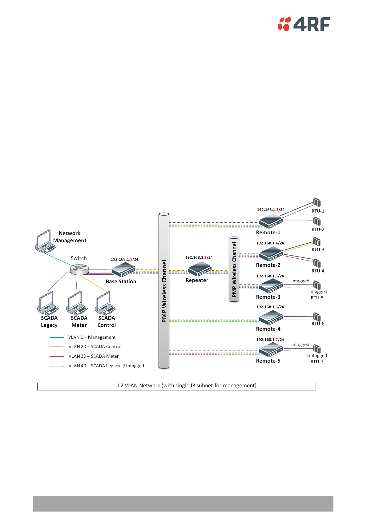
64 | Product Architecture
Aprisa SR+ Product Description
VLAN Bridge Mode Description
General – Aprisa SR+ VLAN Bridge
Aprisa SR+ works in the point-to-multipoint (PMP) network as a standard VLAN bridge with the Ethernet
and wireless / radio as interfaces and serial ports using terminal server as a virtual interface.
The Aprisa SR+ is a standard IEEE 802.1q VLAN bridge, where the FDB table is created by the bridge
learning / aging process. New MACs are learnt and the FDB table updated. Unused MACs are aged out and
flushed automatically after aging period.
VLANs are statically configured by the user on the ports where a Virtual LAN is required across the radio
network. An example of VLAN isolation of traffic type is shown in the figure below, where RTUs #1, 4 and
6 together with SCADA meter master form a Virtual LAN which is isolated from the other devices, even
though they are on the same physical network. VLAN management can be used to manage with external
NMS all the Aprisa SR+ devices on the radio network, and is automatically created with a VLAN ID = 1
default value. The VLAN ID can be changed by the user later on.
Each device in the Aprisa SR+ bridge is identified by its own IP address, as shown in the figure.

Product Architecture | 65
Aprisa SR+ Product Description
VLANs – Single, Double and Trunk VLAN ports
The Aprisa SR+ supports single VLAN (CVLAN), double VLAN (SVLAN) and trunk VLAN.
A single VLAN can be used to segregate traffic type.
A double VLAN can be used to distinguish between Aprisa SR+ sub-networks (base-repeater-remote),
where the outer SVLAN is used to identify the sub-network and the CVLAN is used to identify the traffic
type. In this case, a double tagged VLAN will be forwarded across the Industrial LAN network and switched
based on the SVLAN to the appropriate Aprisa SR+ sub-network. When packet enters the Aprisa SR+
network, the SVLAN will be stripped off (removed) and the forwarding will be done based on the CVLAN,
so only a single VLAN will pass through over the radio network and double VLAN will be valid on the
borders of the radio network.
Trunk VLAN is also supported by the Aprisa SR+ where the user can configure multiple VLANs on a specific
Ethernet port, creating a trunk VLAN port. For example, in the above figure, a single trunk VLAN port is
created between the switch and the Aprisa SR+ base station, carrying VLAN ID #1, 20, 30 and 40.
VLAN Manipulation – Add / Remove VLAN Tags
In order to support double VLAN and different device types connected to the Aprisa SR+ e.g. switches,
RTUs, etc, which can be VLAN tagged or untagged / plain Ethernet devices, add / remove VLAN
manipulation is required.
In an Aprisa SR+ VLAN tagged network, a remote Aprisa SR+ connected to a plain RTU without VLAN
support, will remove (strip-off) the VLAN tag from the packet before sending it to the RTU. On the other
direction, when the RTU is sending an untagged packet, the Aprisa SR+ will add (append) an appropriate
user pre-configure VLAN tag before sending it over the air to the base station. This is shown in the above
figure on untagged RTU #5 and 7.
QoS using VLAN
VLANs carry 3 priority bits (PCP field) in the VLAN tag allowing prioritization of VLAN tagged traffic types
with 8 levels of priority (where 7 is the highest priority and 0 is the lowest priority). The Aprisa SR+
supports QoS (Quality of Service) where the priority bits in the VLAN tagged frame are evaluated and
mapped to four priority levels and four queues supported by the Aprisa SR+ radio. Packets in the queues
are then scheduled out in a strict priority fashion for transmission over-the-air as per the priority level
from high to low.

66 | Product Architecture
Aprisa SR+ Product Description
Avoiding Narrow Band Radio Traffic Overloading
The Aprisa SR+ supports mechanisms to prevent narrowband radio network overload:
1. L3/L4 Filtering
The L3 filtering can be used to block undesired traffic from being transferred on the narrow band channel,
occupying the channel and risking the SCADA critical traffic. L3/4 filtering has the ability to block a known
IP address and applications using TCP/IP or UDP/IP protocols with multiple filtering rules. The L3 (/L4)
filter can block/forward (discard/process) a specific IP address and a range of IP addresses. Each IP
addressing filtering rule set can also be set to filter a L4 TCP or UDP port/s which in most cases relates to
specific applications as per IANA official and unofficial well-known ports. For example, filter and block Email SMTP or TFTP protocol as undesired traffic over the SCADA network. The user can block a specific or
range of IP port addresses, examples SMTP (Simple Mail Transfer Protocol) TCP port 25 or TFTP (Simple
Trivial File Transfer Protocol) UDP port 69.
2. L2 Address Filtering
L2 Filtering (Bridge Mode) provides the ability to filter radio link traffic based on specified Layer 2 MAC
addresses. Destination MAC (DA) addresses and a Source MAC (SA) addresses and protocol type (ARP, VLAN,
IPv4, IPv6 or Any type) that meet the filtering criteria will be transmitted over the radio link. Traffic that
does not meet the filtering criteria will not be transmitted over the radio link.
3. L2 Port VLANs Ingress Filtering and QoS
Double VLAN (Bridge Mode)
Double VLAN is used to distinguish/segregate between different radio sub-networks (Base-repeatersremotes). Traffic with double VLANs which are not destined to a specific sub-network will be discarded on
the ingress of the radio sub-network, avoiding the overload of the radio sub-network.
Single VLAN (Bridge Mode)
Single VLAN is used to distinguish/segregate between different traffic types assigned by the user in its
industrial corporate LAN. In order to avoid the overload of the radio network, traffic with single VLANs
which are not destined to a specific radio network will be discarded on the Ethernet ingress port of the
radio network. All single VLANs which set and are eligible will be transmitted over the radio link.
QoS using 802.1p priority bits (Bridge Mode)
The priority bits can be used in the VLAN tagged frames to prioritized critical mission SCADA traffic and
assure SCADA operation related to any other unimportant traffic. In this case, traffic base on VLAN priority
(priority 0 to 7) entered to one of the four priority queues of the Aprisa SR/SR+ (Very High, High, Medium
and Low). Traffic leaves the queues (to the radio network) from highest priority to lowest in a strict
priority fashion.
4. Ethernet port QoS
The Aprisa SR+ supports ‘Ethernet Per Port Prioritization’. Each Ethernet port can be assigned a priority
and traffic shall be prioritized accordingly. This is quite useful in networks where customers do not use
VLANs or cannot use 802.1p prioritization.

Product Architecture | 67
Aprisa SR+ Product Description
5. Ethernet Data and Management Priority and Background Bulk Data Transfer Rate
Alternatively to VLAN priority, users can control the Ethernet traffic priority (vs serial), management
priority and rate in order to control the traffic load of the radio network, where important and high
priority data (SCADA) will pass-through first assuring SCADA network operation. The user can set the use of
the Ethernet Data Priority, which controls the priority of the Ethernet customer traffic relative to the
serial customer traffic and can be set to one of the four queues. The Ethernet Management Priority
controls the priority of the Ethernet management traffic relative to Ethernet customer traffic and can be
set to one of the four queues. The Background Bulk Data Transfer Rate sets the data transfer rate (high,
medium, low) for large amounts of management data.
6. Ethernet Packet Time to Live
Another aspect of avoiding overload radio network is the Ethernet packet TTL, which is used to prevent
old, redundant packets being transmitted through the radio network. This sets the time an Ethernet
packet is allowed to live in the system before being dropped if it cannot be transmitted over the air.
7. Robust Header Compression (ROHC) and Payload Compression
Aprisa SR+ supports ROHC (Robust Header Compression RFC3095). ROHC is a standard way to compress IP,
UDP and TCP headers and this significantly increases IP traffic throughput especially in narrow band
network.
Aprisa SR+ supports payload compression. A Lempel–Ziv (LZ) algorithm is used to efficiently compress up to
50% traffic with high percentage of repetitive strings. Both serial and Ethernet / IP payload traffic are
compressed.

68 | Product Architecture
Aprisa SR+ Product Description
Product Architecture
The following are the key components of the Aprisa SR+ design:
Dual high performance ΣΔ fractional-N synthesizers to allow for full duplex operation
Wideband design electronically tunes over entire band
Proven low noise and spurious technology with over 50dB of SNR easily achieved
Power amplifier linearity
Unique temperature compensated pre-distortion system improves the efficiency and linearity of
the entire transmitter chain for non-constant envelope modulation systems
Simple IQ modulation line up reduces part count and improves MTBF
No mixing stages so no spurious responses present at the transmitter output
Digital control loops used for controlling power amplifier current and transmit output power, allows for
faster ramping and settling times with less error
Tx turn-on time limited primarily by PA ramping
Robust, closed-loop power control – fast, accurate power ramp up and down
Highly rugged N-Channel RF Power LDMOS transistors for the power amplifier
High efficiency (>50% PAE at 10W)
Very low thermal resistance (1.0°C/W)
Direct IQ down-conversion
Excellent Intermodulation distortion characteristics as channel filter can be placed directly after
the mixer without impacting noise figure
Digital channel filtering allows for multiple bandwidths with the same hardware
Low parts count and no crystal filters help to keep receiver performance extremely stable over
temperature
Integrated heat sink
Limits number of mechanical interfaces
Fin design optimized for natural convection
Monitoring and software control
Temperature control loop shuts down the transmitter when the temperature exceeds continuous
operation at 70°C
Monitoring of RSSI and PA current to ensure the RF hardware is functioning to specification
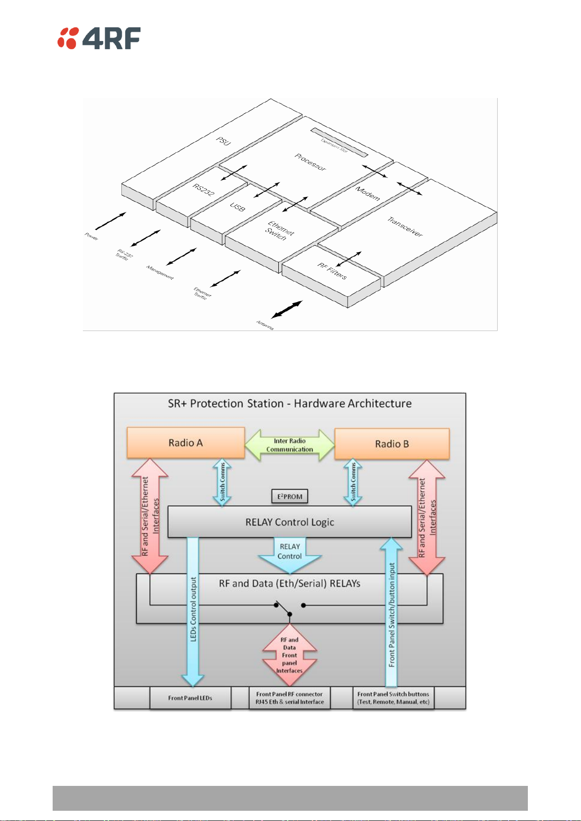
Product Architecture | 69
Aprisa SR+ Product Description
Aprisa SR+ Radio Block Diagram
Aprisa SR+ Protected Station Block Diagram

70 | Contact Us
Aprisa SR+ Product Description
4RF Limited
26 Glover Street, Ngauranga
PO Box 13-506
Wellington 6032
New Zealand
Email address
support@4rf.com
Website
www.4rf.com
Phone number
+64 4 499 6000
Fax number
+64 4 473 4447
Attention
Customer Services
7. Contact Us
For further information or assistance, please contact Customer Support or your local 4RF representative.
Our area representative contact details are available from our website:
 Loading...