


2573

3M
™
Dynatel
™
Cable/Pipe/Fault Locator
2550/2573 Series
Operator’s Manual
2550 Pipe/Cable Locator
2550-iD Pipe/Cable and Marker Locator
2573 Cable/Pipe/Fault Locator
2573-iD Cable/Pipe/Fault and Marker Locator
June 2014
78-9000-0192-2 Rev C 3

2 78-9000-0192-2 Rev C
Contents
1. Safety Information ...........................................................................................................6
2. About This Manual...........................................................................................................7
3. Quick Start .......................................................................................................................8
A. Transmitter Battery Installation ..............................................................................8
B. Receiver Battery Installation ...................................................................................9
C. Cleaning Receiver and Transmitter Units .............................................................10
D. Service and Accessories ........................................................................................10
E. Transmitter 2550 Keypad and Connector Denitions ...........................................10
F. Transmitter 2573Keypad and Connector Denitions.............................................11
G. Maximum Transmitter Output ..............................................................................12
H. Rechargeable Battery Information ........................................................................12
I. Receiver 2550 Keypad Denitions .........................................................................13
J. Receiver 2573 Keypad Denitions .........................................................................14
4. Menu Displays ...............................................................................................................15
A. Main Menu/Locate Menu ......................................................................................15
5. Conguring The Receiver ..............................................................................................18
A. Selecting Depth Units ...........................................................................................18
B. Setting the Receiver Clock ....................................................................................18
C. Selecting a Language ............................................................................................18
D. Enabling/Disabling Locating Frequencies ............................................................19
E. Selecting Locate Modes (Antenna Modes) ...........................................................19
F. Selecting External Jack Frequencies (Tone Frequencies) ......................................20
G. Creating User Dened Frequencies ......................................................................20
H. Filtering Power Frequency Interference ...............................................................21
I. Selecting Locating Audio .......................................................................................21
J. Adjusting Display Contrast ....................................................................................21
6. Locating Buried Cables And Pipes ................................................................................22
A. Transmitter Connections .......................................................................................22
7. Receiver Locating Trace Modes ....................................................................................29
A. Trace View (T-View) .............................................................................................29
B. Special Peak (Spl Pk) ............................................................................................30
C. Induction Peak (Ind Pk) .........................................................................................30
D. Directional Peak (Dir Pk) ......................................................................................31
E. Directional Null (DirNull) .....................................................................................32
F. Expanded Mode .....................................................................................................33
8. Depth and Current Estimate ...........................................................................................33
9. Locating Frequencies .....................................................................................................34
A. Active Frequencies ................................................................................................34
B. Power Frequencies ................................................................................................34
C. Passive Frequencies ...............................................................................................34
D. Auxiliary Frequencies ...........................................................................................34
10. Locating in Directional Peak Mode .............................................................................36
11. Locating Active Duct Probes (Sondes) ........................................................................38
A. Determining Active Duct Probe Depth .................................................................39

78-9000-0192-2 Rev C 3
12. Locating Buried Sheath Faults And Earth Return Faults ............................................40
A. Transmitter Setup ..................................................................................................40
B. Pinpointing the Buried Fault .................................................................................41
13. Locating 3M
™
Electronic Markers and 3M
™
iD Markers ............................................43
A. Enabling/Disabling Marker Types .......................................................................43
B. Alert Mode .............................................................................................................43
C. Single Marker Locate ............................................................................................44
D. Dual Marker Locate ..............................................................................................45
E. 3M iD Marker Depth .............................................................................................45
F. Passive Electronic Marker (Non-iD) Depth ...........................................................46
14. Creating/Editing Templates for 3M
™
iD Markers ........................................................47
A. Creating New Templates .......................................................................................47
B. Editing Templates ..................................................................................................49
15. Writing 3M iD Markers ...............................................................................................50
A. Modifying Marker Data to be Written ..................................................................51
16. Reading 3M iD Markers ..............................................................................................53
17. Reviewing Marker Read/Write History .......................................................................53
A. Read History .........................................................................................................53
B. Write History [SK] ................................................................................................54
18. GPS Compatibility Operation ......................................................................................54
A. Capturing the GPS Coordinates (Capture Mode / Mode 1) ..................................55
B. Sending 3M iD Marker Data to GPS (Capture-Transmit Mode / Mode 2) ...........56
C. Path Mapping with GPS ........................................................................................56
19. Additional Applications ...............................................................................................58
A. Aerial Faults (Toning) ..........................................................................................58
B. Cable Identication ...............................................................................................59
20. Help Mode ...................................................................................................................60
21. 3M
™
Dynatel
™
PC Tool Kit and Locator Software Upgrades ......................................61
22. Self Test of Receiver ....................................................................................................61
23. Product Description And Optional Accessories ...........................................................62
A. Product Description ...............................................................................................62
B. Standard Congurations ........................................................................................62
C. Optional 3M
™
Accessories for 3M Dynatel
™
Locators .........................................63
24. Receiver Specications ................................................................................................64
25. 12-Watt Transmitter Specications ..............................................................................66
26. Environmental and Regulatory Specications .............................................................67
27. Rechargeable Battery Information ...............................................................................67

4 78-9000-0192-2 Rev C
Congratulations! You have just purchased one of the finest, most advanced locating
devices available today!
The 3M
™
Dynatel
™
Pipe/Cable Locators 2550 Series and 3M
™
Dynatel
™
Cable/Pipe/
Fault Locators 2573 Series are designed with all of the functionality of previous
Dynatel models plus the availability of 6 active locating frequencies and trace view
locating mode, while the iD versions have the enhanced capability to read and write
user information into the 3M iD markers. Information such as a pre-programmed
identification number, facility data, application type, placement date and other details
can all be read, stored and downloaded to your PC for enhanced resource management
with this revolutionary equipment. The Dynatel 2550-iD Pipe/Cable Locators and
Dynatel 2573-iD Cable/Pipe/Fault Locators will also search for two different types
of utility markers simultaneously. When used in conjunction with a hand-held GPS
device, the ability to transmit path and marker coordinates multiplies the potential to
the mapping industry. This equipment provides a simple system for mapping utility
information directly into CAD and GIS systems. The 2550/2573 Series transmitters are
12 watt units. They provide .5 watts, 3 watts and 12 watts of output power. 12 watts is
attained by utilizing the Cigarette Lighter Adapter or External Rechargeable Battery.
3M is dedicated to bringing you premium equipment with outstanding reliability, backed
by one of the best warranties in the business and outstanding service.
Visit our website at www.3M.com/dynatel for more application notes and product
information.
78-9000-0192-2 Rev C 5
1. Safety Information
Please read, understand and follow all safety information contained in these instructions
prior to the use of the 3M
™
Dynatel
™
Pipe/Cable Locators 2500 Series. Retain these
instructions for future reference.
Intended Use
The 3M Cable/Pipe/Fault 2550/2573 Series Locators are used to identify the place-
ment of underground utility lines. The system must be installed as specified in the
3M
™
Dynatel
™
Cable/Pipe/Fault Locator 2550/2573 Series Operator's Manual. It has
not been evaluated for other uses or locations. If this equipment is used in a manner not
specified by 3M, the protections provided by the equipment may be impaired.
Explanation of Signal Word Consequences
! Warning:
Indicates hazardous situation which if not avoided, could result in
death or serious injury.
! Caution:
Indicates hazardous situation which if not avoided, could result in
minor or moderate injury.
Explanation of Product Safety Label Symbols
Do not throw away in normal trash.
c
Warning: Risk of electric shock
! WARNING
This WARNING applies to the following 3M Dyna-Couplers;
• 3" (75 mm) - Part number 3001
• 4.5" (114 mm) - Part number 4001
• 6" (150 mm) - Part number 1196
• All accessory kits containing any of the listed Dyna-Couplers - Part numbers 3019, 4519,
1196/C
A potential for electrical shock exists when using the Dyna-Coupler on cables energized with
electrical power. Use appropriate safety procedures.
DO NOT USE ON CABLES CARRYING IN EXCESS OF 600 VOLTS RMS.

6 78-9000-0192-2 Rev C
! WARNING
This WARNING applies to the use of the Direct Connect Cables and the Transmitter.
To avoid potential shock, or electrically damaging the Transmitter, when setting up the
Transmitter to locate using the Direct Connect method, follow these basic steps;
• ALWAYS plug the Direct Connect Cable into the Transmitter Output Jack [T-6] BEFORE
connecting the leads to the cable/pipe to be located and the ground rod.
– Connect the red lead to the cable/pipe.
– Connect the black lead to ground rod.
A POTENTIAL FOR ELECTRICAL SHOCK, AND/OR TRANSMITTER ELECTRICAL DAMAGE, EXISTS
WHEN USING THE DIRECT CONNECT CABLE ON CABLES ENERGIZED WITH ELECTRICAL POWER
IF THE ABOVE INSTRUCTIONS ARE NOT FOLLOWED. USE APPROPRIATE SAFETY PROCEDURES.
CHECK VOLTAGE BEFORE CONNECTING TRANSMITTER. VOLTAGE HIGHER THAN 240 VOLTS WILL
DAMAGE EQUIPMENT. FOLLOW STANDARD PROCEDURES FOR REDUCING THE VOLTAGE.
2. About This Manual
There are two basic models included in the 3M Dynatel Locator 2500 loctor Series. The
2550 is designed for pipe/cable locating. The 2573 loctor is designed for cable/pipe and
fault locating. The iD option (read/write capability to 3M
™
iD Markers) is available for
both models. The 2550/2573 Series transmitters are 12 watt units. They provide .5 watts, 3
watts and 12 watts of output power. 12 watts is attained by utilizing the Cigarette Lighter
Adapter or External Rechargeable Battery. This instruction manual will include all features.
All instructions are applicable to all products, unless noted.
The 12-watt transmitter offers additional power output levels for improved induction
performance and 8 kHz (low frequency) induction for shallow facilities, such as risers.
The maximum output power in Direct Connect method is reduced to comply with FCC
limits. (FCC limits: 10 watts at 33 kHz and 1 watt at 82 kHz and 200 kHz)
In order to demonstrate all available functions, some illustrations depict the 2573-iD
receiver unit. The 2550 receivers and transmitters may vary from the illustrations shown.
78-9000-0192-2 Rev C 7
3. Quick Start
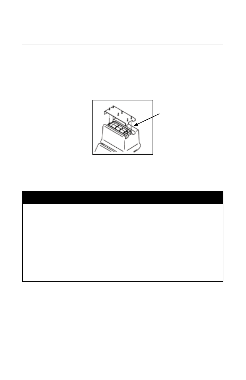
A. Transmitter Battery Installation
Loosen the six screws on the battery compartment cover on the bottom of the transmitter.
Remove the cover.
Install six ‘C’ size alkaline cell batteries (LR14) into the compartment as indicated by
the polarity symbols (+ and –).
Replace the cover and tighten the screws.
Press and hold off [T-1] to manually test the batteries. The display and audio will
indicate one of the following levels: (OK w/solid tone = good; LO w/beeping tone =
low; "--" w/no tone = replace)
! CAUTION
To reduce the risks associated with fire and explosion:
• Do not short, excessively heat, or dispose of batteries in re.
• Install batteries with proper polarity.
• Use only Alkaline "C" (LR14) sized batteries.
• Do not charge batteries.
• Do not use leaking batteries.
To reduce the risks associated with environmental contamination:
• Dispose of batteries and electronic components in accordance with all regulations.
• Ensure batteries are installed with correct polarity.
• Always remove batteries when storing the units for long periods of time.
6 'C' size (LR14)
Alkaline Batteries
8 78-9000-0192-2 Rev C
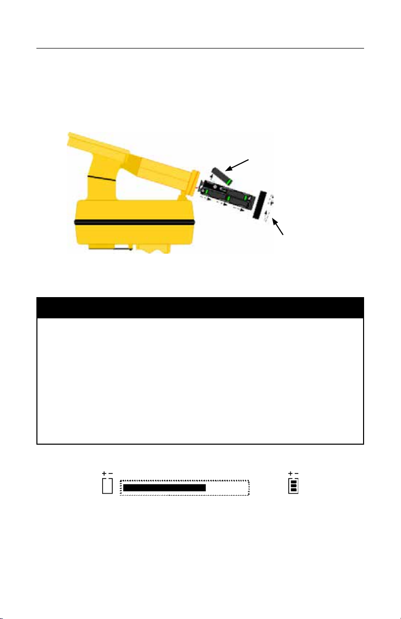
B. Receiver Battery Installation
Remove cap from receiver handle.
Install eight ‘AA’ size alkaline batteries (LR6) into the battery holder as indicated by the
polarity symbols (+ and –).
Attach battery holder to the PP3 connector in the receiver handle, and slide holder into
the handle. Replace the cap.
8 “AA” (LR6)
Alkaline Batteries
1. Twist cap to open battery
compartment.
2. Slide battery compartment
out of handle.
! CAUTION
To reduce the risks associated with fire and explosion:
• Do not short, excessively heat, or dispose of batteries in re.
• Install batteries with proper polarity.
• Use only Alkaline "AA" (LR 6) sized batteries.
• Do not charge batteries.
• Do not use leaking batteries.
To reduce the risks associated with environmental contamination:
• Dispose of batteries and electronic components in accordance with all regulations.
• Ensure batteries are installed with correct polarity.
• Always remove batteries when storing the units for long periods of time.
The receiver batteries are tested for two seconds every time the unit is turned on.
The bar graph on the display will fill to the relative battery level.
The Battery Icon [12] (2573); [[11] (2550)] on the Locate Display will continuously
indicate the battery level.

78-9000-0192-2 Rev C 9
C. Cleaning Receiver and Transmitter Units
To clean the receiver and transmitter units, wipe with a damp cloth.
D. Service and Accessories
Information regarding service, accessories, or replacement parts can be obtained by
contacting 3M at 1-800-426-8688.
This equipment does not require annual calibration or maintenance.
E. Transmitter 2550 Keypad and Connector Definitions
off
+
-
o
Frequency
on
on
Output Level
Dynatel
TM
2550
T-1 T-2 T-3 T-4 T-5 T-6 T-7
[T-1] off: Turns unit off and performs battery test.
[T-2] on - Ohm-meter: Turns the unit on and places the unit in Ohm-meter mode. This
measures the continuity of the trace conductor/pipe and its far-end ground.
[T-3] on - Frequency: Turns the unit on and places the unit in Trace mode.
Select Frequency: Press Frequency [T-3] repeatedly to cycle through the
transmitter's active frequencies (577 Hz, 1 kHz, 8 kHz, 33 kHz, 82 kHz and 200
kHz). The selected frequency will be displayed [T-4]. ‘ALL’ indicates that the
following active frequencies are transmitting simultaneously: 577 Hz, 8 kHz, 33 kHz
and 200 kHz.
[T-4] Digital Display:
Indicator Flags: These flags coincide with the operational mode of the transmitter.
Starting from bottom left to upper right; Ohm-meter [T-2], Voltage (at start up the
transmitter checks for foreign voltage), Output Level [T-5] (no flag = normal output;
flag = high output; flashing flag = maximum output) and Trace mode [T-3].
Digital Display: Indicates frequency, relative current, resistance, battery level and
voltage (if present on target).
[T-5] Output Level: Cycles output power level; normal, high and maximum.
Normal=No Flag; High=Flag; Maximum=Flashing Flag (indicated in Digital Display [T-4])
NOTE: An external 12-volt power source is required to obtain Maximum Output level.
NOTE: 12-watt output level varies by frequency. Output is limited to 10 watts at 33
kHz and 1 watt at 82 kHz and 200 kHz using the direct connection method.
[T-6] Output Jack: Port for direct connect cables or Dyna-coupler cable.
[T-7] External Jack: Port to connect cigarette lighter adapter cable, or rechargeable
battery (2200RB). Input voltage level: 9-18 VDC.

10 78-9000-0192-2 Rev C
F. Transmitter 2573Keypad and Connector Definitions
off
+
-
o
Trace
on
on
Output Level
Dynatel
TM
2573
T-1 T-2 T-3 T- 4 T-5 T-6 T-7
[T-1] off: Turns unit off and performs battery test.
[T-2] on: Ohm-meter/Fault Locate/Tone: Turns the unit on and cycles through the
following commands when pressed repeatedly.
Ohm-meter: Measures the continuity of the trace conductor/pipe and its far-end
ground. It is also used to measure the fault resistance to earth.
Fault Locate: In this mode, the transmitter sends two alternating locating frequencies
(577 Hz and 33 kHz) as well as fault signals 10 and 20 Hz.
Tone: In the tone mode, the transmitter generates 577 Hz and 200 kHz signals.
[T-3] on: Trace (frequency): Turns the unit on and places the unit in Trace mode.
Select Frequency: Press Trace [T-3] repeatedly to cycle through the transmitter's
active frequencies (577 Hz, 1 kHz, 8 kHz, 33 kHz, 82 kHz and 200 kHz). The
selected frequency will be displayed [T-4]. ‘ALL’ indicates that the following active
frequencies are transmitting simultaneously: 577 Hz, 8 kHz, 33 kHz and 200 kHz.
[T-4] Digital Display:
Indicator Flags: These flags coincide with the operational mode of the transmitter.
(From top left to bottom right) Fault Locate mode [T-2], Tone mode [T-2], Trace
mode [T-3], Ohm-meter [T-2], Voltage (at start up the transmitter checks for foreign
voltage), and the Output Level [T-5] (no flag = normal output; flag = high output;
flashing flag = maximum output).
Digital Display: Indicates frequency, relative current, resistance, battery level and
voltage (if present on target).
[T-5] Output Level: Cycles output power level; normal, high and maximum.
Normal=No Flag; High=Flag; Maximum=Flashing Flag (indicated in Digital Display [T-4])
NOTE: An external 12-volt power source is required to obtain Maximum Output level.
NOTE: 12-watt output level varies by frequency. Output is limited to 10 watts at
33 kHz and 1 watt at 82 kHz and 200 kHz using the direct connection method.
[T-6] Output Jack: Port for direct connect cables or Dyna-coupler cable.
[T-7] External Jack: Port to connect cigarette lighter adapter cable, or rechargeable
battery (2200RB). Input voltage level: 9-18 VDC. (Only on 12-watt transmitters.)
78-9000-0192-2 Rev C 11
G. Maximum Transmitter Output
An external 12V DC source is required for 12-Watt Output (Max setting) using a 12-watt
transmitter. Connecting the rechargeable battery (2200RB) to the External Jack [T-7]
will provide this external source, or the cigarette lighter adapter cable (included with
high-powered units) can be used to connect the DC power from a vehicle’s battery
source to the transmitter’s External Jack [T-7].
Press Output [T-5] twice for maximum output power mode.
The indicator flag (in [T-4]) will flash when the transmitter is in maximum output mode.
Note: The external DC source does not charge the internal batteries.
! WARNING
To reduce the risk associated with hazardous voltage:
• Potential for electric shock exists when handling connection cables while the transmitter is
ON. Make all connections prior to powering on the unit. Turn transmitter OFF before handling
connection cables.
• Voltage greater than 240 volts will damage equipment and could cause personal injury or
death. Make all connections before turning on the transmitter. Follow standard procedures
for reducing the voltage.
• Do not change or modify this product in any way.
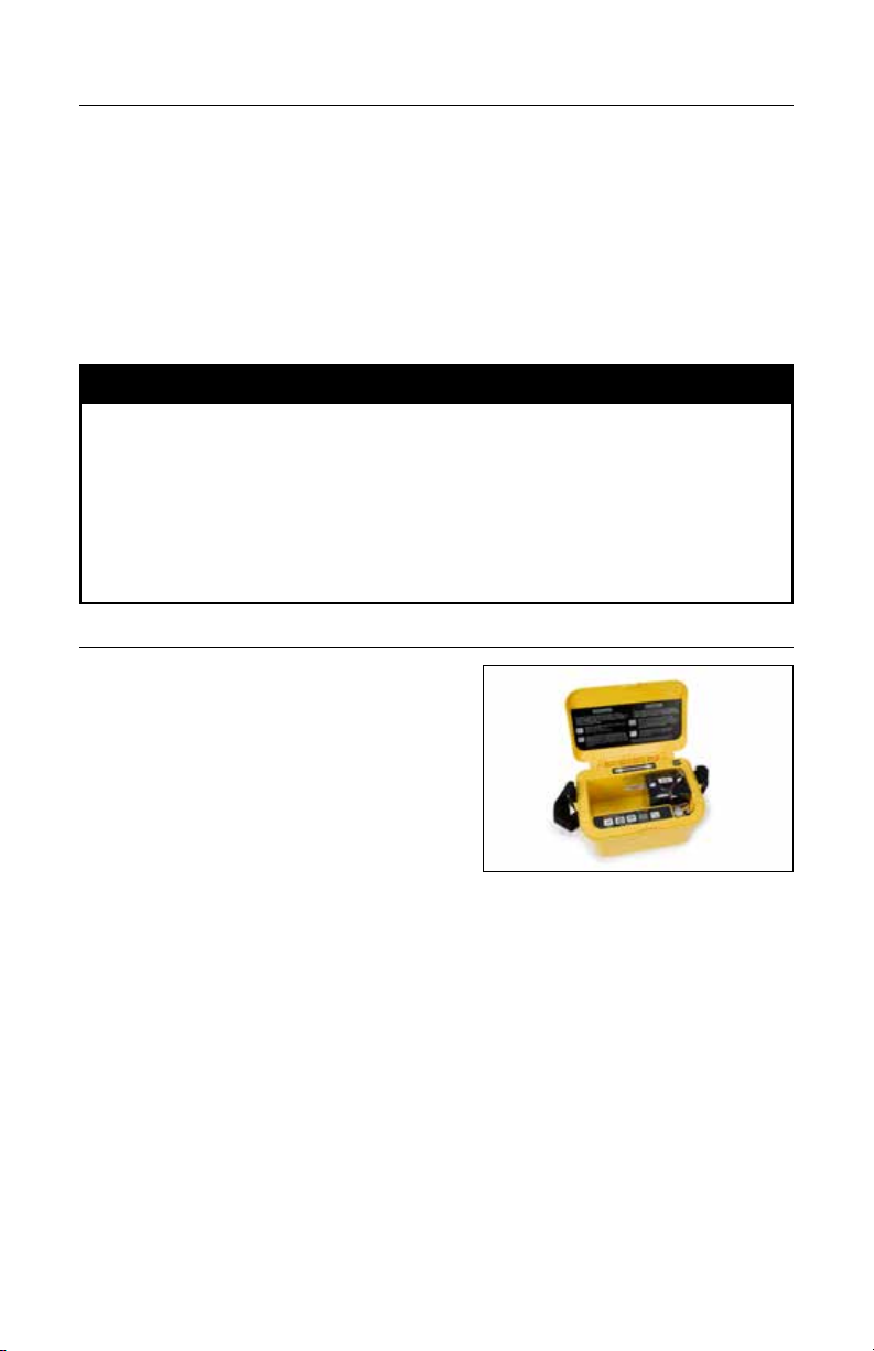
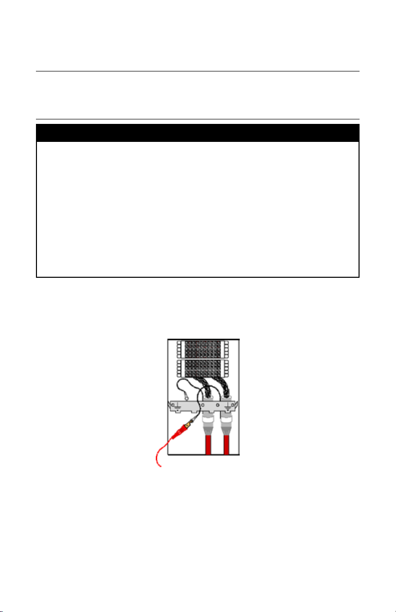
H. Rechargeable Battery Information
The maintenance-free sealed lead (Pb)-acid
3M
™
Dynatel
™
Rechargeable Battery 2200RB
can be used as an auxiliary battery in
3M
™
Dynatel
™
2500 Series 12 Watt Transmitters.
It plugs into the External Jack [T-7] and provides
power for the transmitter. When the rechargeable
battery is plugged in, normal output, high output,
and maximum output are available. When the
rechargeable battery is connected to the
transmitter, the alkaline batteries are bypassed.
The rechargeable battery is a lead acid battery rated at 5.4 amp-hours and is equipped with
a user replaceable fuse (5A/32V).
Note: The internal batteries must be at least 5.4 volts. Do not remove the alkaline
batteries from the transmitter when using the rechargeable battery. Rechargeable
battery, or cigarette lighter adapter cable, is required for maximum output level.
Rechargeable battery is shown installed in the well of the transmitter case.

12 78-9000-0192-2 Rev C
I. Receiver 2550 Keypad and Display Definitions
[10]
[11]
[12]
[13]
[1]
[9]
[8]
[7]
[6]
[5]
[SK]
[2] [3] [4]
14
15
16
Access panel on
bottom side of
Receiver under
rubber cover
[1] On/Off (Power): Turns unit on and off.
[2] TRACE (Locate) MODE: Toggles between Cable View locate mode and the four
other locate modes (cycles through available modes via the Mode soft key when in the
Cable/Pipe Locate display.
[3] GAIN: Adjusts the sensitivity of the receiver either up (+) or down (-) to maintain a
satisfactory signal level.
[4] DEPTH: Measures depth of target.
[5] Menu / OK: Sets the receiver to trace mode for locating cable or pipe and displays
Locate options, 3M iD Marker templates and writing mode options, setup screens for
configuration of the unit, i.e.: clock, language, depth units, marker data and frequencies,
COM settings and Help files. Also acknowledges setup entries (OK).
[SK] Soft Keys: There are four soft keys (yellow keys) on the receiver. The function
of each key is shown above the yellow key on the display screen. The functions will
change, depending on the operation mode of the receiver. For instruction purposes in this
manual, the display command is followed by [SK] to identify it as a soft key.
[6] BULB: Toggles the display backlight low, high, and off.
[7] Gain Level: Displays relative gain level.
[8] Signal Strength: Digital reading of the signal strength that the receiver is detecting
from the target.
[9] Speaker Volume Icon: Indicates the relative volume level of the receiver. When the
third ring is dotted and ‘xpnd' appears below the speaker volume icon, the receiver is in
“Expander” mode. This mode is used to pinpoint the target cable or pipe.
[10] Bar Graph: Graphical representation of the received signal.
[11] Battery Icon: Indicates battery level.
[12] Speaker Volume Control: Adjusts the volume of the receiver (off, low, medium,
high, and xpnd).
[13] Soft Key Commands: Definitions for each of the four soft key functions.
[14] External Jack: Port to connect cables from external devices such as the earth
contact frame (A-Frame), a second 3M Dyna-Coupler or a toning coil.
78-9000-0192-2 Rev C 13
[15] Serial Port: RS232 port to connect the receiver to a PC via serial cable or USB-to-
Serial Adapter cable.
[16] Earphone Jack: Will fit standard 1/8 inch (3.175 mm) mini-jack mono earphone
plug (not included).
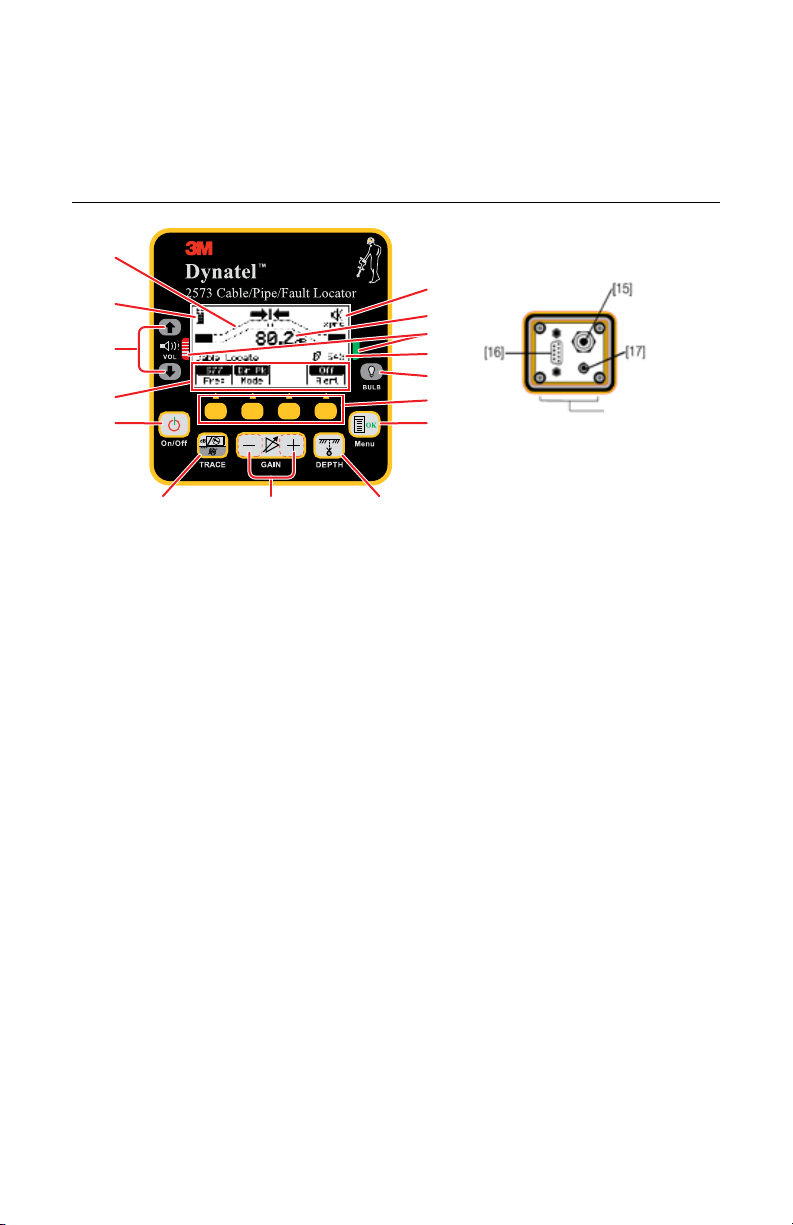
J. 2573 Receiver Keypad and Display Definitions
[11]
[12]
[13]
[14]
[1]
[10]
[9]
[8]
[7]
[6]
[5]
[SK]
[2] [3] [4]
Access panel on
bottom side of
Receiver
[1] On/Off (Power): Turns unit on and off.
[2] TRACE (Locate) MODE: Toggles between Cable View locate mode and the four
other locate modes (cycles through available modes via the Mode soft key when in the
Cable/Pipe Locate display.
[3] GAIN: Adjusts the sensitivity of the receiver either up (+) or down (-) to maintain a
satisfactory signal level.
[4] DEPTH: Measures depth of target.
[5] Menu / OK: Sets the receiver to trace mode for locating cable or pipe and displays
Locate options, 3M iD Marker templates and writing mode options, setup screens for
configuration of the unit, i.e.: clock, language, depth units, marker data and frequencies,
COM settings and Help files. Also acknowledges setup entries (OK).
[SK] Soft Keys: There are four soft keys (yellow keys) on the receiver. The function
of each key is shown above the yellow key on the display screen. The functions will
change, depending on the operation mode of the receiver. For instruction purposes in this
manual, the display command is followed by [SK] to identify it as a soft key.
[6] BULB: Toggles the display backlight low, high, and off.
[7] Gain Level: Displays relative gain level.
[8] Fault Finding Direction Indicators: Corresponds to the Earth Contact Frame
(A-Frame) probe (leg) colors.
[9] Signal Strength: Digital reading of the signal strength that the receiver is detecting
from the target.
[10] Speaker Volume Icon: Indicates the relative volume level of the receiver. When the
third ring is dotted and ‘xpnd' appears below the speaker volume icon, the receiver is in
“Expander” mode. This mode is used to pinpoint the target cable or pipe.
[11] Bar Graph: Graphical representation of the received signal.
14 78-9000-0192-2 Rev C
[12] Battery Icon: Indicates battery level.
[13] Speaker Volume Control: Adjusts the volume of the receiver (off, low, medium,
high, and xpnd).
[14] Soft Key Commands: Definitions for each of the four soft key functions.
[15] External Jack: Port to connect cables from external devices such as the earth
contact frame (A-Frame), a second 3M
™
Dyna-Coupler or a toning coil.
[16] Serial Port: RS232 port to connect the receiver to a PC via serial cable or USB-to-
Serial Adapter cable.
[17] Earphone Jack: Will fit standard 1/8 inch (3.175 mm) mini-jack mono earphone
plug (not included).
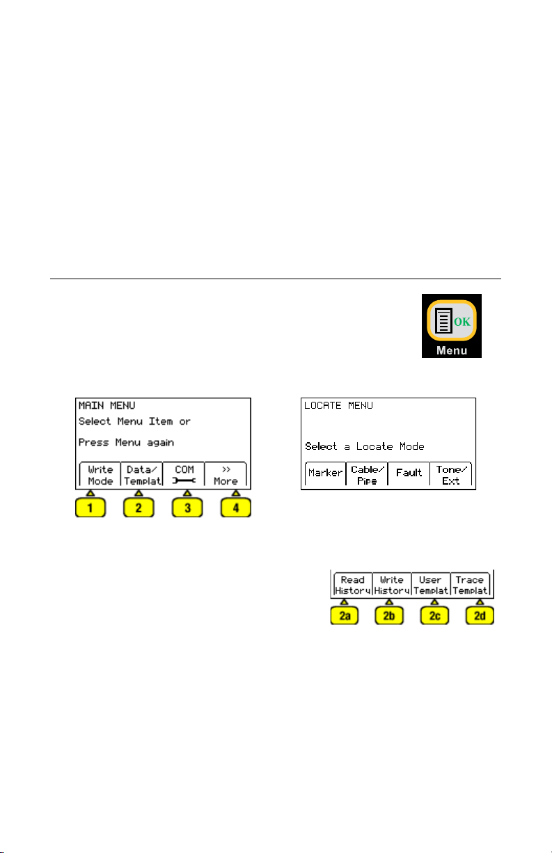
4. Menu Displays
A. Main Menu/Locate Menu
When the Menu/OK [5] button is pressed, the display will toggle
between the MAIN MENU display and LOCATE MENU display.
The function appears on the display above each soft key [SK].
MAIN MENU Display LOCATE MENU Display
1. Write Mode: System used to write information to 3M
™
iD Markers
2. Data/Template: Displays marker history and
template creation/selection displays:
a. Read History – 100 memory locations for
Read 3M
™
iD Markers
b. Write History – 100 memory locations for
written 3M
™
iD Markers
c. User Templates – Create and edit iD
templates for 3M
™
iD Markers (max =32)
d. Trace Templates – Create and edit
templates used to identify path (max = 5)
78-9000-0192-2 Rev C 15
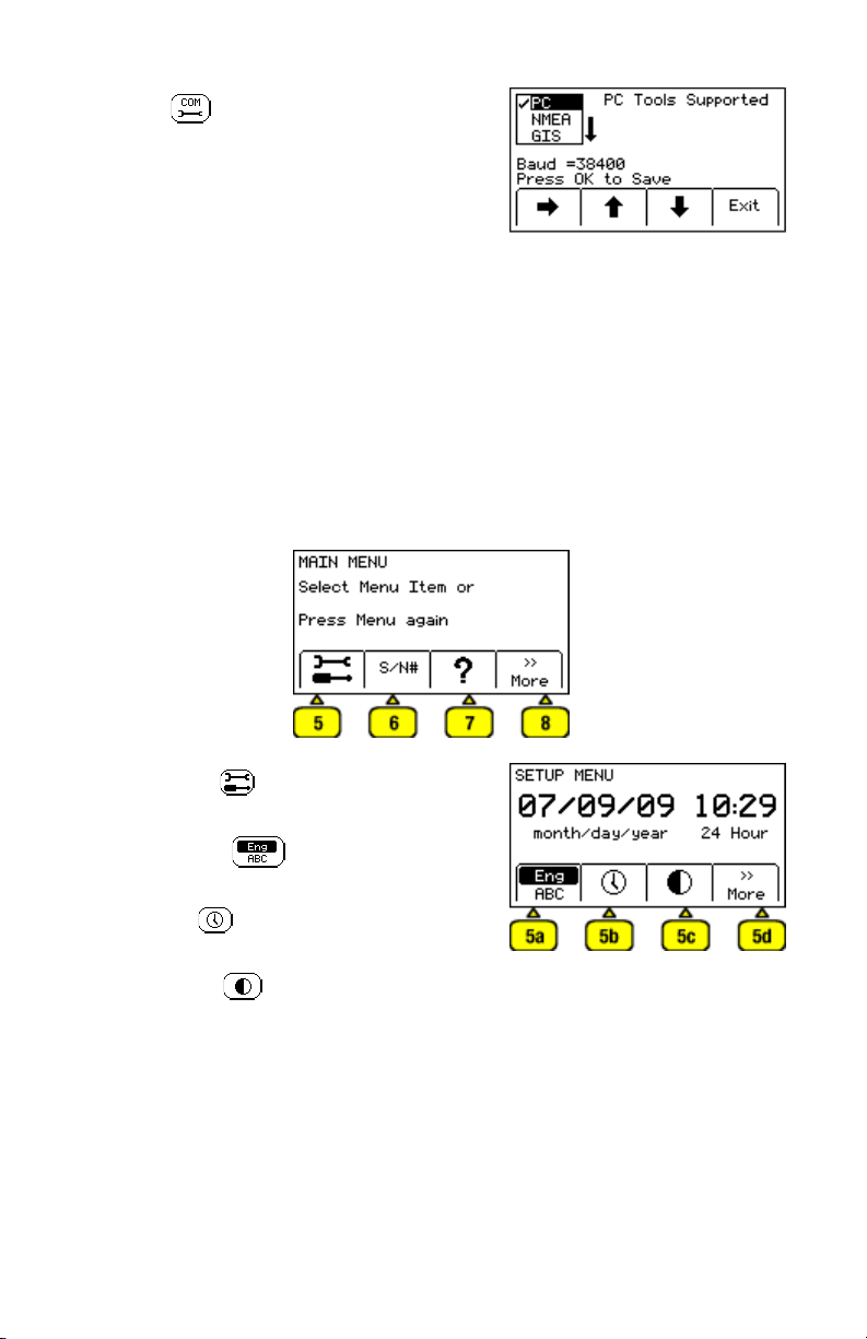
3. COM : Displays second level COM
Port setting display to configure RS232 port
communication with different devices –
a. PC – Receiver will communicate to a
computer
b. NMEA – Port is configured to accept
coordinates from GPS device
c. GIS – Port is configured to send 3M
™
iD
Marker information or path information
to GPS device and receive coordinates
from GPS device
d. PDA – receiver will send 3M
™
iD Marker
and path information in ASCII string.
4. >>More: Advances to next Main Menu display
MAIN MENU Display 2
5. Setup Tools : Displays second and third
level displays for receiver configuration
a. Language
– Toggles between
English and alternate language
b. Clock
– Date and time stamped on
marker information and depth readings.
c. Contrast
– Adjusts contrast of LCD
display.
d. >>More - Advances to next menu display
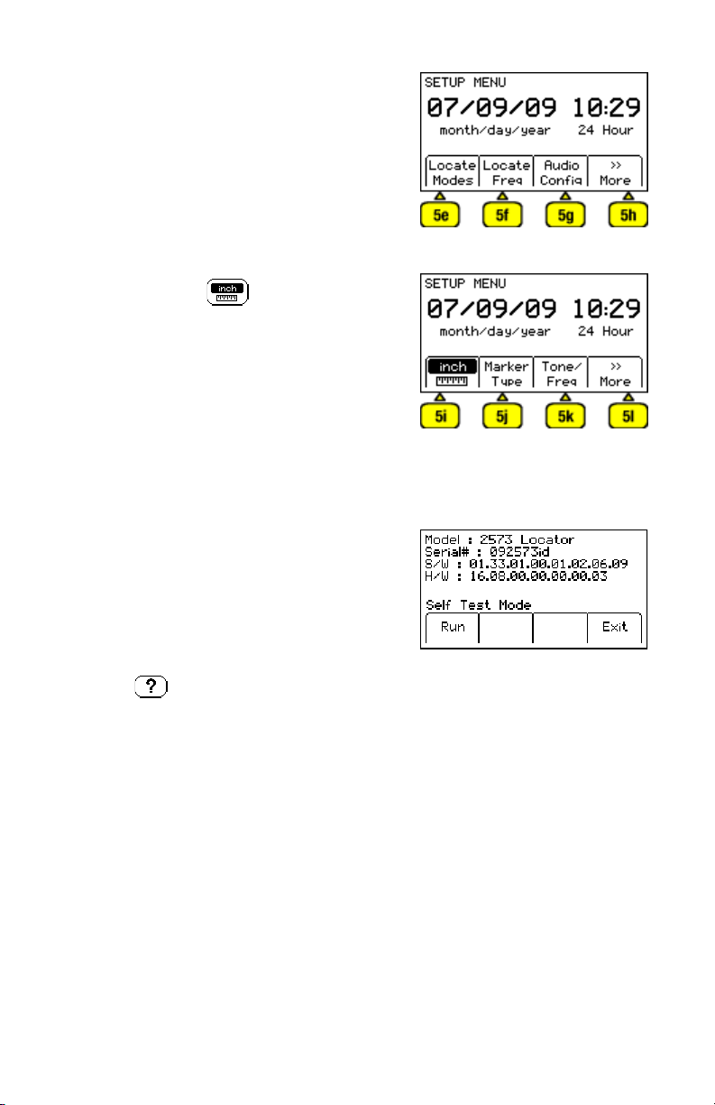
16 78-9000-0192-2 Rev C
e. Locate Modes – enable or disable locate
modes
f. Locate Frequencies – enable and disable
receiver frequencies in locate mode
g. Audio Configuration – Select audio
response of unit in Directional Peak and
Trace View modes
h. >>More - Advances to next menu display
i. Depth Units – Choose unit of
measure; in, ft-in, or cm
j. Marker Type – enable and disable marker
utility types
k. Tone/Freq - External Port or Tone
Frequencies – enable and disable frequencies
that are detectable through the external port
of the receiver
l. >>More - Returns to first SETUP MENU
display
6. S/N#/Self Test: Displays information about unit
and can perform a self check test
7. Help : Offers the user on-screen
instructions
8. >>More: Returns to first Main Menu display
78-9000-0192-2 Rev C 17
5. Configuring The Receiver
In the setup mode, the units of depth measurement, time, date, and date format can be
set. The receiver can be configured to detect only certain frequencies and/or specific
utility markers (3M
™
Dynatel
™
Receivers 2550-iD and 2573-iD only) and activate
certain locating modes. User defined frequencies can be programmed, language of the
receiver can be selected, and tone frequencies set.
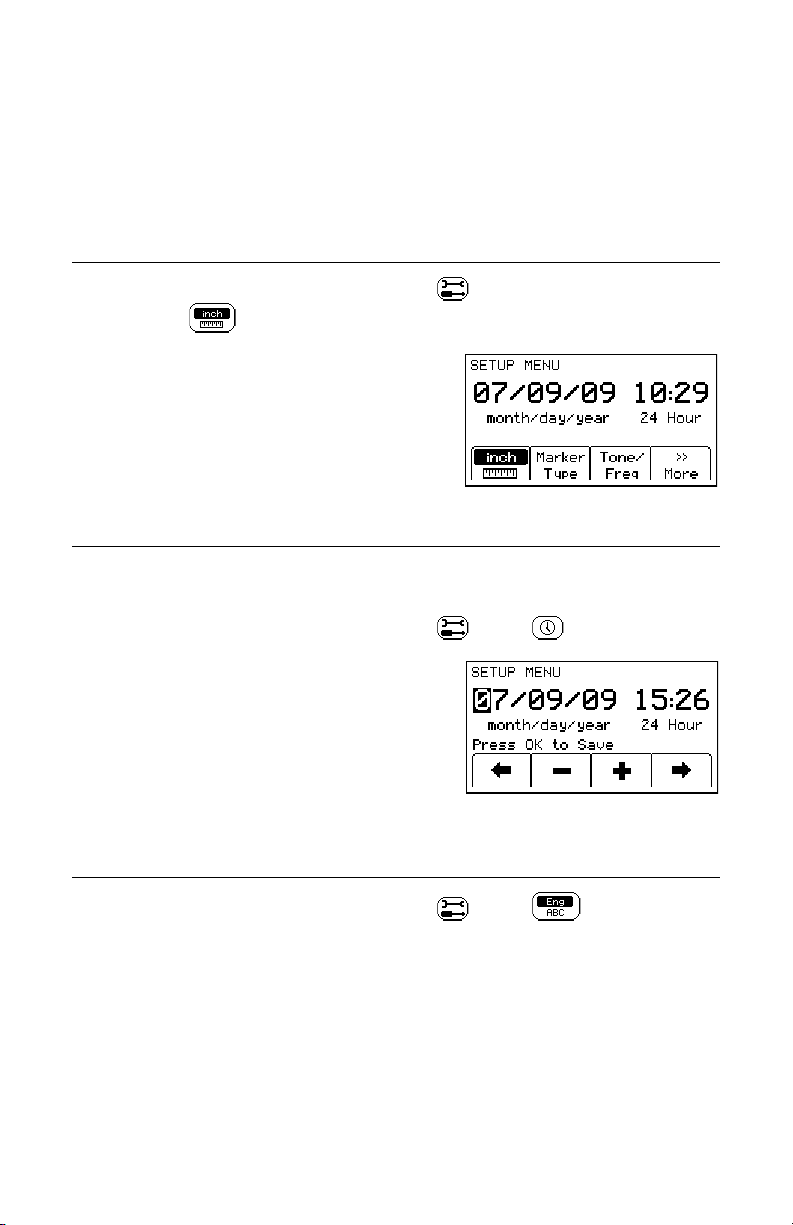
A. Selecting Depth Units
Menu/OK [5:Toggle to MAIN MENU] + >>More [SK:4] + [SK:5] + >>More [SK:d] +
>>More[SK:h] +
[SKToggle:i]
• The soft key command will toggle between inches
(in), centimeters (cm), and feet/inches (ft-in).
B. Setting the Receiver Clock
Set the time, date, and date format of the receiver. Depth and Current measurements are
time and date stamped, as well as read and write marker information (iD units only).
Menu/OK [5:Toggle to MAIN MENU] + >>More [SK:4] +
[SK:5] + [SK:b]
• Press the left/right arrow [SK] to highlight the
digit of the date or time to change.
• Press the + or - [SK] to increment or decrement.
• When the date format is highlighted, the format
will toggle between mm/dd/yy and dd/mm/yy.
• Press Menu/OK [5] to save.
C. Selecting a Language
Menu/OK [5:Toggle to MAIN MENU] + >>More [SK:4] + [SK:5] + [SKToggle:a]
The soft key command will toggle between available languages. Alternate languages
can be uploaded to the receiver using the 3M
™
Dynatel
™
PCTools Software. The 3M
™
Dynatel
™
PC Tool Kit Software is available free of charge at www.3M.com/dynatel
under the Software section; 2550/2573/2250M/2273M/1420 Locator PC Tools xx.x.x
(EXE xx.xMB).
18 78-9000-0192-2 Rev C
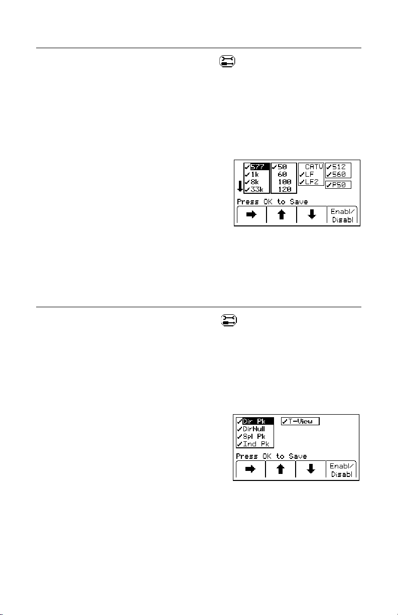
D. Enabling/Disabling Locating Frequencies
Menu/OK [5:Toggle to MAIN MENU] + >>More [SK:4] + [SK:5] + >>More [SK:d] +
LocateFreq[SK:f]
The user can select the frequencies that the receiver will detect. All the available
frequencies are listed in four groups (Left to Right: Active, Power, Passive, and
Auxiliary). The Auxiliary group also contains the User Defined Frequencies. (See 5G.
Creating User Defined Frequencies.) The box below the Auxiliary group allows the
selection of filtering for 50 Hz or 60 Hz passive signals when User Defined frequencies
have been chosen for locating.
• Press the right arrow [SK] to move the highlight
bar to the section of frequencies to enable, or
disable.
• Press the up/down arrows [SK] to highlight the
specific frequency.
• Press Enabl/Disabl [SK]. (Enable denoted by )
• Repeat steps 2 & 3 to enable/disable other
frequencies.
• Press Menu/OK [5] to save.
E. Selecting Locate Modes (Antenna Modes)
Menu/OK [5: Toggle to MAIN MENU] + More>> [SK:4] + [SK:5] + More>> [SK:d] + Locate
Modes [SK:e]
The user can select the locate modes (antenna modes) that the receiver utilizes. There
are five locate modes that are available; Trace View (T-View), Directional Peak (Dir Pk),
Directional Null (DirNull), Special Peak (Spl Pk) and Induction Peak (Ind Pk).
All five modes are activated when shipped. The user can deactivate any of the modes
that will not be used.
• Press the up/down arrows [SK] to highlight a
specific locate mode in the first column.
• Press the right arrow [SK] to move the highlight
bar to the second column, or back to the first
column.
• Press Enabl/Disabl [SK]. (Enable denoted by )
• Repeat steps 2 & 3 to enable/disable other locate
modes.
• Press Menu/OK [5] to save.
78-9000-0192-2 Rev C 19
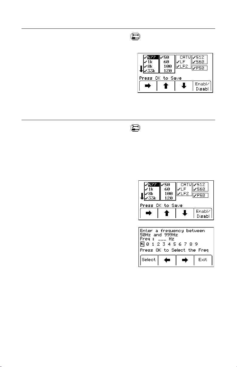
F. Selecting External Jack Frequencies (Tone Frequencies)
Menu/OK [5:Toggle to MAIN MENU] + >>More [SK:4] + [SK:5] + >>More [SK:d] +
>>More[SK:h] + Tone/Freq [SK:k]
A coupler can be plugged into the External Jack
[15] ([14] on 2550 locator) of the receiver and
used to identify 50 Hz or 60 Hz cables. (See 19.
Additional Applications: B: Cable Identification.)
The same procedure as above (Section 5D) is
followed for selecting frequencies that can be
detected by the External Jack [15] ([14] on 2550
locator) found on the bottom of the receiver.
G. Creating User Defined Frequencies
Menu/OK [5:Toggle to MAIN MENU] + >>More [SK:4] + [SK:5] + >>More [SK:d] +
Locate Freq [SK:f]
There are four user defined frequencies available on the receiver. (These frequencies
must be between 50 Hz and 999 Hz.) These frequencies are found in the column on the
far right of the Locate Freq display (Auxiliary frequencies). These frequencies, once
programmed, will appear under the Aux [SK] frequency list when Freq [SK] is selected
in the Locate mode.
To program the user defined frequencies press the
right arrow [SK] to highlight the Auxiliary group
of frequencies. Press the up/down arrows [SK]
to highlight the user frequency to program. Press
Enabl/Disabl [SK].
Press the left/right arrows [SK] to move the square
cursor to a digit. Press Select [SK] to enter the
number in the frequency field.
Press Menu/OK [5] to save the programmed
frequency, or press Exit [SK] to cancel. The
frequency will appear in the locate frequency display
as U###, where ### represents the programmed
frequency.
Note: To redefine a previously programmed user
frequency, highlight the frequency, press enabl/
disabl, select the back arrow with the cursor, and
press select to delete the previous entry.
20 78-9000-0192-2 Rev C
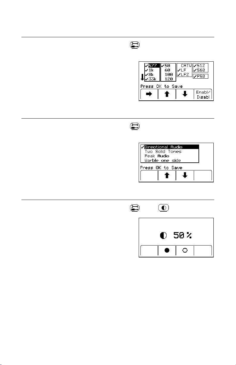
H. Filtering Power Frequency Interference
(User Defined FrequenciesOnly)
Menu/OK [5:Toggle to MAIN MENU] + >>More [SK:4] + [SK:5] + >>More [SK:d] +
Locate Freq [SK:f]
In order to filter out unwanted power influences
while locating with user-defined frequencies, verify
the correct frequency is selected for your location
(default 60 Hz). Press Menu/OK [5] to save.
I. Selecting Locating Audio
Menu/OK [5:Toggle to MAIN MENU] + >>More [SK:4] + [SK:5] + >>More [SK:d] +
AudioConfig [SK:g]
The user can choose the audio response of the
receiver when using the Directional Peak or Trace
View modes for path locating. Highlight the audio
selection and press Menu/OK [5] to save.
J. Adjusting Display Contrast
Menu/OK [5:Toggle to MAIN MENU] + >>More [SK:4] + [SK:5] + [SK:c]
The display contrast can be adjusted higher or lower.
• Press the solid circle [SK] to darken the display.
• Press the open circle [SK] to lighten the display.
• Press Menu/OK [5] to save.
78-9000-0192-2 Rev C 21
6. Locating Buried Cables And Pipes
A. Transmitter Connections
Perform a battery test. Use one of the following three methods to produce a trace signal
on the target pipe or cable.
1. Direct Connect Method
! WARNING
This WARNING applies to the use of the Direct Connect Cables and the Transmitter.
To avoid potential shock, or electrically damaging the Transmitter, when setting up the
Transmitter to locate using the Direct Connect method, follow these basic steps;
• ALWAYS plug the Direct Connect Cable into the Transmitter Output Jack [T-6] BEFORE
connecting the leads to the cable/pipe to be located and the ground rod.
– Connect the red lead to the cable/pipe.
– Connect the black lead to ground rod.
A POTENTIAL FOR ELECTRICAL SHOCK, AND/OR TRANSMITTER ELECTRICAL DAMAGE, EXISTS
WHEN USING THE DIRECT CONNECT CABLE ON CABLES ENERGIZED WITH ELECTRICAL POWER
IF THE ABOVE INSTRUCTIONS ARE NOT FOLLOWED. USE APPROPRIATE SAFETY PROCEDURES.
CHECK VOLTAGE BEFORE CONNECTING TRANSMITTER. VOLTAGE HIGHER THAN 240 VOLTS WILL
DAMAGE EQUIPMENT. FOLLOW STANDARD PROCEDURES FOR REDUCING THE VOLTAGE.
• Plug the direct connect cable into the Output Jack [T-6] of the transmitter. Connect
the black clip to the ground rod. Place the ground rod in the earth perpendicular to
the suspected cable/pipe path. If necessary, extend the black lead with the Ground
Extension Cable (#9043 available separately).
• Remove the ground bonding and attach the red clip to the shield of the cable, pipe,
or target conductor. (If locating power cables, the red clip can be attached to the
transformer cabinet, or the meter box). Metal contact must be made between the red
clip and the transformer cabinet or meter box. If painted, some paint will need to be
removed/scraped off to allow metal-to-metal contact.
• Turn the transmitter on by pressing Ohms [T-2]. The continuity of the circuit will be
measured. The results are displayed on the Digital Display [T-4] in ohms and as an
audible tone.
 Loading...