


Instructions and Parts List
TM
3M-Matic
200a |
Type 39600 |
Adjustable |
|
Case Sealer |
|
with
AccuGlideTM
Taping Heads
Serial No.
For reference, record machine serial number here.
3M Packaging Systems Division
3M Center, Building 220-8W-01
St. Paul, MN 55144-1000
Important Safety
Information
Read "Important Safeguards", pages 3-5 and also
operating "Warnings", page 14 BEFORE INSTALLING OR OPERATING THIS EQUIPMENT.
Spare Parts
It is recommended you immediately order the spare parts listed on page 31, Section I and page 17, Section II. These parts are expected to wear through normal use and should be kept on hand to minimize production delays.
"3M-Matic"and "AccuGlide" are Trademarks of 3M, St. Paul, MN 55144-1000
Litho in U.S.A.
© 3M 1999 44-0009-1894-4 (F69.0)

Replacement Parts and Service Information
To Our Customers:
This is the 3M-Matic™/AccuGlide™/Scotch™ brand equipment you ordered. It has been set up and tested in the factory with "Scotch" brand tapes. If technical assistance or replacement parts are needed, call or Fax the appropriate number listed below.
Included with each machine is an Instructions and Parts List manual.
Technical Assistance:
3M-Matic™ Helpline – 1-800/328 1390. Please provide the customer support coordinator with the machine number, machine type/model and serial number. If you have a technical question that does not require an immediate response, you may Fax it to 715/381 0248.
Replacement Parts and Additional Manuals
Order parts by part number, part description and quantity required. Also, when ordering parts and/or additional manuals, include machine name, number and type. A parts order form is provided at the back of this manual.
3M/Tape Dispenser Parts |
|
241 Venture Drive |
1-800/344 9883 |
Amery, WI 54001-1325 |
FAX# 715/268 8153 |
Minimum billing on parts orders will be $25.00. Replacement part prices available on request. $10.00 restocking charge per invoice on returned parts.
Note : Outside the U.S., contact the local 3M subsidiary for parts ordering information.
3
3M Packaging Systems Division
3M Center, Building 220-8W-01
St. Paul, MN 55144-1000
"3M-Matic", "AccuGlide" and “Scotch” are trademarks of 3M, St. Paul, Minnesota 55144-1000
Printed in U.S.A.
© 3M 1999 44-0009-1851-4(E79.0)

Replacement Parts And Service Information
To Our Customers:
This is the 3M-Matic™/AccuGlide™/Scotch™ brand equipment you ordered. It has been set up and tested in the factory with "Scotch" brand tapes. If any problems occur when operating this equipment, and you desire a service call, or phone consultation, call, write or Fax the appropriate number listed below.
Included with each machine is an Instructions and Parts List manual.
SERVICE, REPLACEMENT PARTS AND ADDITIONAL MANUALS AVAILABLE DIRECT FROM:
Order parts by part number, part description and quantity required. Also, when ordering parts and/or additional manuals, include machine name, number and type.
3
3M Packaging Systems Division
3M Center, Building 220-8W-01 St. Paul, MN 55144-1000 1-800/328 1390
"3M-Matic", "AccuGlide" and “Scotch” are trademarks of 3M, St. Paul, Minnesota 55144-1000
Printed in U.S.A.
© 3M 1999 44-0009-1852-2(D79.0)

Instruction Manual
200a, Adjustable Case Sealer, Type 39600
This instruction manual is divided into two sections as follows:
Section I Includes all information related to installation, operation and parts for the case sealer. Section II Includes specific information regarding the AccuGlide™ II STD 2 Inch Taping Heads.
Table of Contents |
Page |
Section I – 200a Adjustable Case Sealer |
|
Description ...................................................................................................................................... |
1 |
Equipment Warranty and Limited Remedy ...................................................................................... |
2 |
200a Contents ................................................................................................................................. |
2 |
Important Safeguards ...................................................................................................................... |
3 - 5 |
Specifications .................................................................................................................................. |
6 - 8 |
Installation and Set-Up .................................................................................................................... |
9 - 11 |
Receiving and Handling ..................................................................................... |
9 |
Machine Set-Up .................................................................................................. |
9 - 11 |
Packaging and Separate Parts ................................................................. |
9 -10 |
Machine Bed Height ................................................................................. |
11 |
Outboard Tape Roll Mounting ................................................................... |
11 |
Tape Leg Length ....................................................................................... |
11 |
Box Size Capacity of Case Sealer ............................................................ |
12 |
Electrical Connection and Controls ........................................................... |
12 |
Initial Start-Up of Case Sealer .................................................................. |
12 |
Operation ........................................................................................................................................ |
13 - 16 |
Electrical On/Off Switch ...................................................................................... |
14 |
Tape Loading/Threading .................................................................................... |
14 |
Box Size Set-Up ................................................................................................. |
15 - 16 |
Box Sealing ........................................................................................................ |
16 |
Maintenance .................................................................................................................................... |
17 - 18 |
Cleaning ............................................................................................................. |
17 |
Lubrication .......................................................................................................... |
17 |
Circuit Breaker .................................................................................................... |
18 |
Knife Replacement, Taping Head ....................................................................... |
18 |
Box Drive Belt Replacement ............................................................................... |
18 |
(Table of Contents continued on next page)
i
Table of Contents (Continued) |
|
Page |
Adjustments ................................................................................................................................... |
|
19 - 21 |
Drive Belt Tension ...................................................................................................... |
|
19 - 20 |
Taping Head Adjustments .......................................................................................... |
|
21 |
Special Set-Up Procedure ............................................................................................................... |
|
23 - 25 |
Changing Tape Leg Length ................................................................................ |
|
23 - 24 |
Box and Machine Bed Height Range ................................................................. |
|
24 - 25 |
Troubleshooting............................................................................................................................... |
|
27 |
Electrical Diagram ........................................................................................................................... |
|
29 |
Parts and Service Information ......................................................................................................... |
|
31 |
Options/Accessories ........................................................................................................................ |
|
32 |
Replacement Parts Illustrations and Parts Lists ..................................................... |
(Yellow Section) |
33 - 57 |
Section II – AccuGlide™ II STD 2 Inch Taping Heads |
|
|
(See Section II for Table of Contents) |
|
|
ii
Description
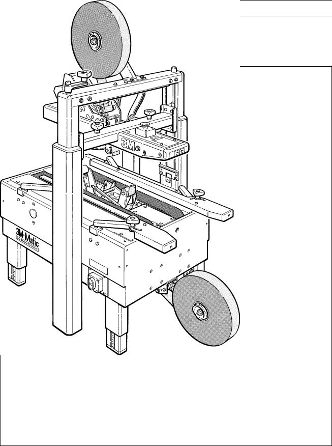
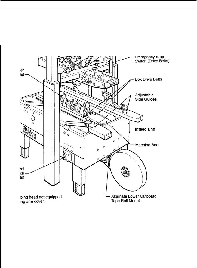
The 3M-MaticTM 200a Adjustable Case Sealer with AccuGlide™ II Taping Heads is designed to apply a “C” clip of Scotch™ brand pressure-sensitive film box sealing tape to the top and bottom center seam of regular slotted containers. The 200a is manually adjustable to a wide range of box sizes (see "Specifications – Box Weight and Size Capacities", Page 7).
3M-MaticTM 200a Adjustable Case Sealer, Type 39600 (Note – Lower tape supply roll and bracket assembly are shown in the alternate location)

Equipment Warranty and Limited Remedy: THE FOLLOWING WARRANTY IS MADE IN LIEU OF ALL OTHER WARRANTIES, EXPRESS OR IMPLIED, INCLUDING, BUT NOT LIMITED TO, THE IMPLIED WARRANTY OF MERCHANTABILITY, THE IMPLIED WARRANTY OF FITNESS FOR A PARTICULAR PURPOSE AND ANY IMPLIED WARRANTY ARISING OUT OF A COURSE OF DEALING, A CUSTOM OR USAGE OF TRADE:
3M sells its 3M-MaticTM 200a Adjustable Case Sealer, Type 39600 with the following warranties:
1.The Taping Head knife, springs and rollers will be free from all defects for ninety (90) days after delivery.
2.All other Taping Head parts will be free from all defects for three (3) years after delivery.
3.The gearmotor will be free from all defects for one (1) year after delivery.
4.All other parts will be free from all defects for ninety (90) days after delivery.
If any part is proved to be defective within its warranty period, then the exclusive remedy and 3M’s and seller’s sole obligation shall be, at 3M’s option, to repair or replace the part, provided the defective part is returned immediately to 3M’s factory or an authorized service station designated by 3M. A part will be presumed to have become defective after its warranty period unless the part is received or 3M is notified of the problem no later than five (5) calendar days after the warranty period. If 3M is unable to repair or replace the part within a reasonable time, then 3M, at its option, will replace the equipment or refund the purchase price. 3M shall have no obligation to provide or pay for the labor required to install the repaired or replacement part. 3M shall have no obligation to repair or replace (1) those parts failing due to operator misuse, carelessness, or due to any accidental cause other than equipment failure, or (2) parts failing due to non-lubrication, inadequate cleaning, improper operating environment, improper utilities or operator error.
Limitation of Liability: 3M and seller shall not be liable for direct, indirect, special, incidental or consequential damages based upon breach of warranty, breach of contract, negligence, strict liability or any other legal theory.
The foregoing Equipment Warranty and Limited Remedy and Limitation of Liability may be changed only by a written agreement signed by authorized officers of 3M and seller.
Contents – 200a Adjustable Case Sealer
(1)200a Adjustable Case Sealer, Type 39600
(1)Upper Assembly Height Adjustment Crank/Hardware
(1)Upper Tape Drum/Bracket/Hardware
(2)Column Stop Bracket/Hardware
(1)Tool/Spare Parts Kit
(1)Instruction and Parts Manual
Scotch™, AccuGlide™, and 3M-MaticTM are Trademarks of 3M, St. Paul, Minnesota 55144-1000
2

Important Safeguards
This safety alert symbol identifies important messages in this manual.
READ AND UNDERSTAND THEM BEFORE INSTALLING OR OPERATING THIS EQUIPMENT.
Important – In the event the following safety labels are damaged or destroyed, they must be replaced to ensure operator safety. A label kit, part number 78-8113-6714-9 is available as a stock item or individual labels can be ordered. See Parts Illustration/List, Section I, pages 56 and 57.
The "Warning – Sharp Knife" label, shown in
Figure 1-1, is attached to both sides of the upper ski assembly at the location of the cut-off knife on the upper taping head. The labels warn operators and service personnel of the very sharp knife used to cut the tape at the end of the tape application.
Figure 1-1 – Knife Warning Label
The "Warning – Hazardous Voltage" label, shown in Figure 1-2, is attached to the electrical enclosure on the lower left side of the machine frame. The label warns service personnel to unplug the power supply before attempting any service work on the case sealer.
Figure 1-2 – Electrical Warning Label
The "Caution – Pinch Point" label, shown in
Figure 1-3, is attached to the center plate at the exit end of the machine bed. The label warns the operator to keep hands out of this area when the drive belts are running.
Figure 1-3 – Pinch Point Caution Label
3
Important Safeguards (Continued)
The "Caution – Pinch Point" label, shown in
Figure 1-4, is attached to the top of the upper assembly crossbar on both sides of the machine. The label reminds operator to keep hands away from compression rollers when machine is running.
Figure 1-4 – Pinch Point Caution Label
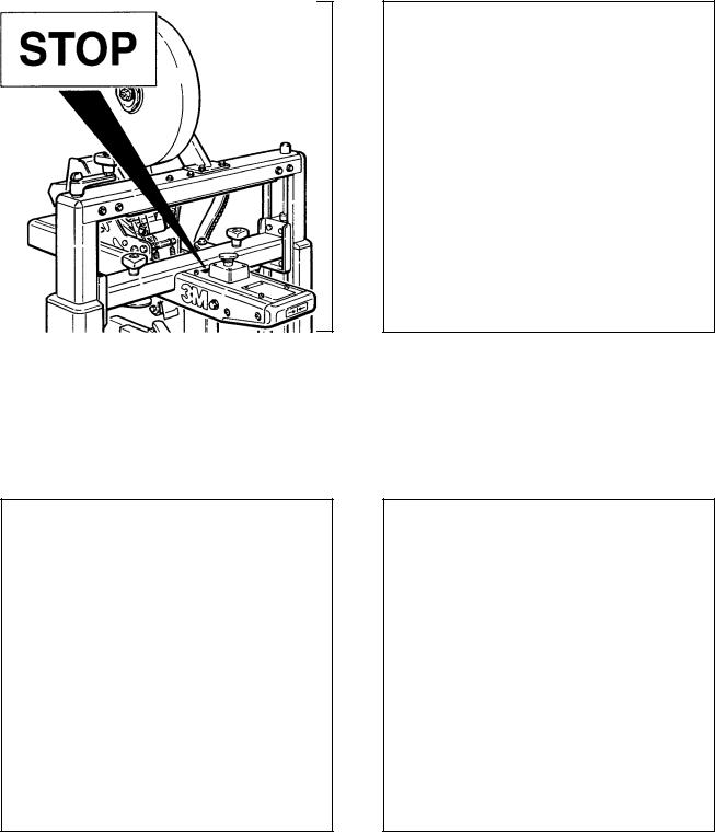
The 200a is equipped with a "Red" emergency stop switch located on the top/front of the upper ski assembly. The "Stop" label, shown in Figure 1-5, is located near the switch and reminds operators and casual personnel of the function of this switch.
Figure 1-5 – Stop Label
The "Safety Instructions" label, shown in
Figure 1-6, is attached to the top/front of the upper ski assembly. The label provides convenient safeguard instructions for the operator and service personnel.
Figure 1-6 – Safety Instruction Label
The "Center Box Here" label, shown in Figure 1-7, is attached to the front of the upper frame to remind the operator of the proper box placement procedure.
Figure 1-7 – Center Box Label
4

Important Safeguards (Continued)
The "Up/Down/Lock" label, shown in Figure 1-8, is located on the top surface, on each side, of the upper column assembly. The label reminds the operator of the direction to turn the height adjustment crank to raise and lower the upper ski/taping head and the locking feature.
Figure 1-8 – Up/Down/Lock Label
The following two labels are located on the upper and lower taping heads. Replacement part numbers for these labels are listed in Section II.
The "Tape Threading Label", shown in Figure 1-9, is attached to the left side of both the upper and lower taping heads.
Figure 1-9 – Tape Threading Label
The "Warning – Sharp Knife" label warns operators and service personnel of the extremely sharp knife used to cut the tape at the end of the box sealing operation. The label, shown in Figure 1-10, is located on the orange knife guard between the applying roller assembly and the buffing roller assembly. Never operate taping head with knife guard removed.
Before working with the taping heads or loading/ threading tape, refer to Figures 3-1 and 3-2 in Section II to identify the knife location. Keep hands out of these areas except as necessary to service the taping heads or to load/thread tape.
Figure 1-10 – Knife Warning Label
5
Specifications
1.Power Requirements:
Electrical - 115 VAC, 60 Hz, 1.9 A (220 watts)
The machine is equipped with a 1/6 HP gearmotor and comes with a standard neoprene covered power cord and a grounded plug. Contact your 3M Representative for power requirements not listed above.
2.Operating Rate:
Box drive belt speed is approximately 0.4 m/s [78 feet per minute].
3.Operating Conditions:
Use in dry, relatively clean environments at 5o to 40o C [40o to 105o F] with clean, dry boxes.
Note: Machine should not be washed down or subjected to conditions causing moisture condensation on components.
4.Tape:
Scotch™ brand pressure-sensitive film box sealing tapes.
5.Tape Width:
36 mm [1 1/2 inch] minimum to 48 mm [2 inch] maximum.
(Specifications continued on next page)
6
Specifications (Continued)
6.Tape Roll Diameter:
Up to 405 mm [16 inch] maximum on a 76.2 mm [3 inch] diameter core. (Accommodates all system roll lengths of Scotch™ brand film tapes.)
7.Tape Application Leg Length – Standard:
70 mm ± 6 mm [2 .75 inch ±.25 inch ]
Tape Application Leg Length – Optional:
50 mm ± 6 mm [2 inch ±.25 inch]
(See "Special Set-Up Procedure – Changing the Tape Leg Length", Page 23.)
8.Box Board:
Style – regular slotted containers – RSC
125 to 275 P.S.I. bursting test, single wall or double wall B or C flute.
9.Box Weight and Size Capacities:
A. Box Weight, filled – 2.3 kg [5 lbs.] minimum, 38.6 kg [85 lbs.] maximum.
B. Box Size: |
Minimum |
Maximum |
|
Length – |
150 mm [6.0 inch] |
Unlimited |
|
Width |
– |
150 mm [6.0 inch]* |
550 mm [21.5 inch] |
Height |
– |
120 mm [4.75 inch]** *** |
620 mm [24.5 inch] *** |
*Cartons narrower than 250 mm [10 inch] in width may require more frequent belt replacement because of limited contact area.
**90 mm [3.5 inch] height with heads adjusted to apply 50 mm [2 inch] tape leg lengths. (See "Special Set-Up Procedure – Changing the Tape Leg Length", Page 23.)
***165 mm [6.5 inch] minimum to 725 mm [28.5 inch] maximum height with columns adjusted to upper position. (See "Special Set-Up Procedure – Box and Machine Bed Height Range", Page 24.)
Special modifications may be available for carton sizes not listed above. Contact your 3M Representative for information.
Note: The case sealer can accommodate most boxes within the size range listed above. However, if the box length (in direction of seal) to box height ratio is .75 or less, then several boxes should be test run to assure proper machine performance.
DETERMINE THE BOX LIMITATIONS BY COMPLETING THIS FORMULA:
BOX LENGTH IN DIRECTION OF SEAL |
MUST BE GREATER THAN .75 |
BOX HEIGHT |
|
Any box ratio approaching this limitation should be test run to assure performance.
(Specifications continued on next page.)
7
Specifications (Continued)
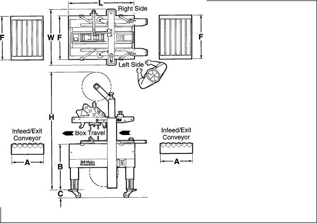
10. Machine Dimensions: |
|
|
|
|
|
||
|
W |
L |
H |
A* |
B |
C** |
F |
|
|
|
|
|
|
|
|
Minimum |
|
|
|
|
|
|
|
mm |
790 |
930 |
1350 |
460 |
610 |
100 |
620 |
[Inches] |
[31] |
[36 1/2] |
[53] |
[18] |
[24***] |
[4] |
[24 1/2] |
Maximum |
|
|
|
|
|
|
|
mm |
|
|
2185 |
|
890 |
|
|
* Infeed/Exit conveyors are optional
**Casters are optional
***When columns are adjusted to upper position, "B" minimum/maximum dimension decreases by 90 mm
[3 1/2 inches] and "H" maximum dimension increases by 100 mm [4 inch]. (See "Special Set-Up Procedure – Box and Machine Bed Height Range", Page 24.)
Weight – 145.6 kg [320 lbs] crated (approximate)
123.4kg [280 lbs] uncrated (approximate)
11.Set-Up Recommendations:
•Machine must be level.
•Customer supplied infeed and exit conveyors (if used) should provide straight and level box entry and exit.
•Exit conveyors (powered or gravity) must convey sealed boxes away from machine.
8

Installation and Set-Up
Receiving And Handling
After the machine has been uncrated, examine the case sealer for damage that might have occurred during transit. If damage is evident, file a damage claim immediately with the transportation company and also notify your 3M Representative.
Machine Set-Up
Important – Read "Warnings", on page 14, before attempting to set-up the case sealer for operation.
The following instructions are presented in the order recommended for setting up and installing the case sealer, as well as for learning the operating functions and adjustments. Following them step by step will result in your thorough understanding of the machine and an installation in your production line that best utilizes the many features built into the case sealer. Refer to Figure 3-1 to identify the various components of the case sealer.
Note – A tool kit consisting of metric open end and hex socket wrenches is provided with the machine. These tools should be adequate to set-up the machine, however, other tools supplied by the customer will be required for machine maintenance.
PACKAGING AND SEPARATE PARTS
1.Lift fiberboard cover off pallet after removing staples at bottom.
2.Remove protective wrapping around machine.
3.Remove hardware that secures case sealer legs to pallet.
4.Cut and remove cable tie that secures black electrical conduit to the electrical mast on top of machine.
5.Cut cable ties that secure upper assembly to machine bed on each side of machine. Remove and discard cable ties and protective foam sheeting.
6.Remove tape drum bracket bolts (4) from top crossbar and install tape drum bracket from parts box on top crossbar as shown in Figure 2-1A.
7.Install height adjustment crank handle on top of left column as shown in Figure 2-1B. Crank upper assembly up high enough to allow clear access to lower taping head. Remove and discard the two cushion shipping blocks.
8.Loosen both side guides, pivot to full open position and re-tighten locking knobs.
9.Wipe protective shipping oil off stainless steel covers on machine bed.
10.Cut and remove cable ties on both upper and lower taping heads. (Applying/buffing rollers are held retracted for shipment.)
WARNING – Follow this step carefully as spring pressure is
applied to applying and buffing arms when cable tie is removed. Keep hands/fingers AWAY from tape cut-off knife under orange knife guard. Knife is extremely sharp and can cause severe injury.
Hold taping head BUFFING ROLLER and cut and remove cable tie that holds applying/buffing arms retracted. See Figure 2-1C. Allow buffing/ applying arms to extend slowly.
9

Figure 2-1 – 200a Frame Set-Up
11.Check for free action of both upper and lower taping heads.
WARNING – Keep hands/fingers away from tape cut-off knife under
orange knife guard. Knife is extremely sharp and can cause severe injury.
Push buffing roller into head to check for free, smooth action of taping heads.
12.Loosen lock knobs and pivot side guides to center position. Install machine stops (from parts box) as shown in Figure 2-1D. Use the lowest hole position and bolt into the lowest threaded insert on the column. (The upper hole position in the stops are only used when the taping heads are adjusted to apply 50 mm
[2 inch] tape legs.)
13.Ensure that the tape drum bracket assembly, located on the lower taping head, is mounted straight down, as shown in Figure 2-2A. The tape drum bracket assembly can be pivoted to provide tape roll clearance in certain cases.
14.Use appropriate material handling equipment to remove the machine from the pallet and move it into position.
Whenever the machine is lifted with a fork truck, insure that the forks span completely across the machine frame and do not contact any wiring or mechanism under the machine frame. In some cases the lower taping head may need to be removed to avoid damage.
CAUTION – Machine weighs approximately 123 kg [280 pounds]
uncrated.
15.Continue with the remainder of the Installation and Set-Up procedure through page 12.
10
Installation and Set-Up (Continued)
MACHINE BED HEIGHT
Adjust machine bed height. The case sealer is equipped with four adjustable legs that are located at the corners of the machine frame. The legs can be adjusted to obtain different machine bed heights from 610 mm [24 in] minimum to 890 mm [35 in] maximum.
Note – Minimum machine bed height can be reduced to 520 mm [20.5 in] by moving outer columns up one set of mounting holes.
However, this change also reduces minimum box height of 120 mm [4.75 in] to 165 mm [6.5 in]. (See "Special Set-Up Procedure – Box/Machine Bed Height Range", page 24.)
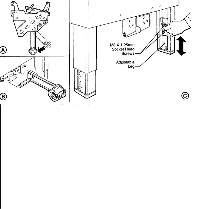
Refer to Figure 2-2C and set the machine bed height as follows:
1.Use appropriate material handling equipment and blocking techniques to raise the machine frame to allow adequate leg adjustment.
2.Loosen, but do not remove, two M8 x 16 socket head screws in one leg (use M6 hex wrench). Adjust the leg length for the desired machine bed height. Retighten the two screws to secure the leg. Adjust all four legs equally.
OUTBOARD TAPE ROLL MOUNTING
(Lower Taping Head Alternate Position)
Remove the tape drum bracket assembly, spacer and fasteners from the lower taping head. Install and secure on the infeed end of the lower frame, as shown in Figure 2-2B.
TAPE LEG LENGTH
Taping heads are pre-set to apply 70 mm [2.75 in] long tape legs. To change tape leg length to 50 mm [2.0 in], see "Special Set-Up Procedure – Changing the Tape Leg Length", page 23.
Figure 2-2 – Machine Bed Height Adjustment and Lower Tape Drum Bracket Position
11

Installation and Set-Up (Continued)
BOX SIZE CAPACITY OF CASE SEALER
At its factory setting, the case sealer handles box sizes up to 620 mm [24.5 in] maximum height. If larger capacity is needed, the machine can be adjusted to accommodate boxes up to 725 mm [28.5 in] high. Refer to "Special Set-Up Procedure – Box and Machine Bed Height Range", page 24. Note – Adjusting machine to accommodate 725 mm [28.5 in] high boxes also increases minimum box size to 165 mm [6.5 in].
ELECTRICAL CONNECTION AND CONTROLS
The electrical control box, located on the lower right side of the machine frame, contains the pre-set circuit breaker. The control box can be located on the opposite side of the machine frame if desired.
A standard three conductor power cord with plug is provided at the back of the electrical control box for 115 Volt, 60 Hz., 1.9 Amp electrical service. The receptacle providing this service shall be properly grounded. Before the power cord is plugged into 115 Volt, 60 Hz outlet make sure that all packaging materials and tools are removed from the machine. Do not plug electrical cord into outlet until ready to run machine.
Use of an extension cord is not recommended. However, if one is needed for temporary use, it must have a wire size of AWG 16 [1.5 mm dia], have a maximum length of 30.5 m [100 ft], and must be properly grounded.
WARNING – To prevent shock and fire hazard: Position extension cord
where it will be out of the way of foot or vehicle traffic. Extension cord is only for temporary use – do not use for a permanent installation.
Note – Machines outside the U.S. may be equipped with 220/240 Volt, 50 Hz systems or other electrical requirements compatible with local practice.
INITIAL START-UP OF CASE SEALER
After completing the "Installation and Set-Up" procedure, continue through "Operation" for tape loading and start-up to be sure case sealer is properly adjusted to run boxes
12
Operation
IMPORTANT – Before operating the case sealer, read the "Important Safeguards", pages 3-5 and "Warnings" on page 14 as well as all of the "Operation" instructions.
Refer to Figure 3-1 below to acquaint yourself with the various components and controls of the case sealer. Also see Figures 3-1 and 3-2 in Section II for taping head components.
Figure 3-1 – 200a Case Sealer Components (Left Front View)
13

Operation (Continued)
 WARNINGS
1.Turn electrical supply off and disconnect before servicing taping heads or performing any adjustments or maintenance on the machine.
2.Do not leave machine running unattended.
3.Before turning drive belts on, be sure no tools or other objects are on the machine bed.
4.Keep hands and loose clothing away from moving belts.
5.Keep hands and clothing away from taping heads when machine is running. A box traveling through the machine causes taping head rollers to retract when box enters and extend as box leaves taping head.
6.Never attempt to work on any part of the machine, load tape or remove jammed boxes from the machine while machine is running.
7.When feeding boxes to the machine by hand, push box in from end only – DO NOT PUSH WITH HANDS ON ANY CORNER OF THE BOX.
8.Both the upper and lower taping heads utilize extremely sharp knives. The knives are located under the orange knife guard which has the 'WARNING – SHARP KNIFE" label. Before loading tape, refer to Figures 3-1 and 3-2 in Section II to identify the knife location. Keep hands out of these areas except as necessary to service the taping heads.
9.Turn drive belts "Off" when machine is not in use.
10.Failure to comply with these warnings could result in severe personal injury and/or equipment damage.
Electrical "On/Off" Switch
The box drive belts are turned on and off ("Off" button is red) with the electrical switch on the side of the machine frame.
Note – The case sealer has a circuit breaker located in the electrical control box on the lower right side of the machine frame. If circuit becomes overloaded and circuit breaker trips, see "Maintenance – Circuit Breaker", page 18.
Emergency Stop Switch
The machine electrical supply can be turned off by pressing the latching emergency stop switch. To restart machine, rotate emergency stop switch (releases switch latch) and then restart machine by pressing "I" (On) button on side of machine frame.
Tape Loading/Threading
See Section II, Pages 7 and 8
Note – If lower tape drum is mounted in alternate lower outboard position, remove taping head from machine bed by pulling straight up, insert threading needle in taping head and replace taping head. Install tape roll on drum (adhesive on tape leg up), thread tape under knurled roller on outboard mount, then attach tape to threading needle and pull tape through taping head with threading needle.
CAUTION – Taping head weighs approximately 7.2 kg [16 pounds]
without tape. Use proper body mechanics when removing or installing taping head.
14
 Loading...