


 Loading...
3M Personal Safety Division
3M™ QUESTemp°™ Heat Stress Monitors
Robust Construction
©3M 2013. All Rights Reserved.
From the
Market Leader
QUESTempo 44 and QUESTempo 46 User Manual

Contents
i Contents
Contents |
|
Introduction.......................................................................................................................................................... |
1 |
QUESTempº Models ............................................................................................................................................ |
1 |
Getting Started..................................................................................................................................................... |
2 |
Up and Running overview................................................................................................................................... |
2 |
Keypad Operation ............................................................................................................................................... |
2 |
I/O Enter key………………………………………………………………………………………………………...3 |
|
Up Arrow key………………………………………………………………………………………………………..3 |
|
Down Arrow key…………………………………………………………………………………………………….3 |
|
Run Stop key………………………………………………………………………………………………………..3 |
|
Escaping or moving back one screen…………………………………………………………………………… 3 |
|
Turning on/off and basic operation ..................................................................................................................... |
4 |
Placing the QUESTempº 44/46 on the job site................................................................................................... |
4 |
Sensors................................................................................................................................................................. |
5 |
About the sensor bar........................................................................................................................................... |
5 |
Globe Thermometer............................................................................................................................................ |
5 |
Waterless Wetbulb Sensor and Relative Humidity Sensor................................................................................. |
5 |
Dry Bulb Thermometer........................................................................................................................................ |
5 |
Remote, Sensors 2 and 3.................................................................................................................................... |
6 |
Tri-sensor weighted average .............................................................................................................................. |
6 |
Measurements ..................................................................................................................................................... |
7 |
Waterless Wetbulb.............................................................................................................................................. |
7 |
Computing Waterless wetbulb and wind speed |
7 |
WetBulb Globe Temperature .............................................................................................................................. |
8 |
Stay Times/Rest Times (QTº46 only) ................................................................................................................. |
8 |
Heat Index/Humidex ........................................................................................................................................... |
8 |
Airflow ................................................................................................................................................................. |
8 |
Thermal Comfort ................................................................................................................................................. |
9 |
Operating QUESTempº 44/46 ........................................................................................................................... |
10 |
View .................................................................................................................................................................. |
10 |
Setup................................................................................................................................................................. |
10 |
Setup for Waterless Wetbulb measurement (airflow rate)................................................................................ |
11 |

ii |
Contents |
|
|
Print................................................................................................................................................................... |
12 |
|
Reset................................................................................................................................................................. |
12 |
|
Run ................................................................................................................................................................... |
12 |
|
Displayed Items ................................................................................................................................................. |
13 |
|
Stay Time.......................................................................................................................................................... |
14 |
|
Data Logging...................................................................................................................................................... |
15 |
|
Electronic sensor check ................................................................................................................................... |
16 |
|
Performing an electronic sensor check............................................................................................................. |
16 |
|
Sensor Alignment.............................................................................................................................................. |
17 |
|
RH Sensor Alignment ....................................................................................................................................... |
17 |
|
Printing ............................................................................................................................................................... |
19 |
|
Serial................................................................................................................................................................. |
19 |
|
Parallel .............................................................................................................................................................. |
20 |
|
Airflow functionality .......................................................................................................................................... |
21 |
|
Operating sequence.......................................................................................................................................... |
22 |
|
Data Logging Airflow......................................................................................................................................... |
22 |
|
Batteries for Air Probe....................................................................................................................................... |
22 |
|
Operational Check............................................................................................................................................. |
22 |
|
Power options.................................................................................................................................................... |
23 |
|
9-Volt Alkaline Battery Replacement ................................................................................................................ |
23 |
|
Approved 9-Volt Batteries ................................................................................................................................. |
23 |
|
NiMH Battery Pack............................................................................................................................................ |
24 |
|
Appendix A: Specifications ............................................................................................................................. |
25 |
|
Appendix B: Heat Exposure Tables................................................................................................................ |
27 |
|
ACGIH............................................................................................................................................................... |
27 |
|
ACGIH Clothing Corrections ............................................................................................................................. |
28 |
|
United States Navy ........................................................................................................................................... |
28 |
|
Flag Conditions for U.S. Navy/Marine Corp. Ashore ........................................................................................ |
30 |
|
Electrical power research institute (EPRI) ........................................................................................................ |
30 |
|
Appendix C: Accessories ................................................................................................................................. |
31 |

iii |
Contents |
|
|
Air Probe Accessories....................................................................................................................................... |
31 |
|
Appendix D: 3MTM Detection Management Software DMS ........................................................................... |
32 |
|
QUESTempo 44/46 ............................................................................................................................................. |
32 |
|
Communication setup ....................................................................................................................................... |
32 |
|
Downloading data with the QT 44/46............................................................................................................... |
34 |
|
Viewing Data in DMS ........................................................................................................................................ |
35 |
|
Selecting a session/study ................................................................................................................................. |
35 |
|
Charts and Graphs in Panel layout view (PLV) page ....................................................................................... |
35 |
|
Reports and Printing ......................................................................................................................................... |
38 |
|
3M Service .......................................................................................................................................................... |
39 |
|
Contacting 3M Technologies ............................................................................................................................ |
39 |
|
Calibration……………………………………………………………………………………………………………….39 |
|
|
Warranty ............................................................................................................................................................. |
39 |

iv |
Contents |
|
|
List of Figures |
|
||
Figure 1-1: QUESTempº 44/46 in a thermal environment ----------------------------------------------------------- |
1 |
||
Figure 1-2: Keypad explained--------------------------------------------------------------------------------------------- |
3 |
||
Figure 1-3: Main menu of the QTº44/46------------------------------------------------------------------------------- |
4 |
||
Figure 1-4: About sensor bar and serial number --------------------------------------------------------------------- |
5 |
||
Figure 1-5: Sensors identified-------------------------------------------------------------------------------------------- |
5 |
||
Figure 1-6: Viewing measured data------------------------------------------------------------------------------------ |
10 |
||
Figure 1-7 |
Setting the airflow for Waterless Wetbulb sensor------------------------------------------------------ |
11 |
|
Figure 1-8 |
Run mode indicator ----------------------------------------------------------------------------------------- |
12 |
|
Figure 1-9 Wet and Dry screen------------------------------------------------------------------------------------------ |
13 |
||
Figure 1-10: Globe screen------------------------------------------------------------------------------------------------ |
13 |
||
Figure 1-11: WBGTi & WBGTo screen---------------------------------------------------------------------------------- |
13 |
||
Figure 1-12: RH and H.I/HU screen ----------------------------------------------------------------------------------- |
13 |
||
Figure 1-13: Air Flow screen on QTº46-------------------------------------------------------------------------------- |
13 |
||
Figure 1-14: Stay times (ACGIH)--------------------------------------------------------------------------------------- |
14 |
||
Figure 1-15: Time & Date screen -------------------------------------------------------------------------------------- |
14 |
||
Figure 1-16: Battery & Memory screen-------------------------------------------------------------------------------- |
14 |
||
Figure 1-17: Navy Stay time screen ----------------------------------------------------------------------------------- |
14 |
||
Figure 1-18: Flag Conditions for U.S. Navy/Marine Corp. Ashore ------------------------------------------------- |
15 |
||
Figure 1-19: EPRI Stay time screen------------------------------------------------------------------------------------ |
15 |
||
Figure 1-20: Main menu with view selected (A) & measurement screen (B) ----------------------------------- |
17 |
||
Figure 1-21: Alignment screen------------------------------------------------------------------------------------------ |
17 |
||
Figure 1-22: Sunshield & placement of finger cot prior to RH verification -------------------------------------- |
17 |
||
Figure 1-23: RH alignment with Low % example-------------------------------------------------------------------- |
18 |
||
Figure 1-24: RH alignment with High% screen ----------------------------------------------------------------------- |
18 |
||
Figure 1-25: Sample printout (page 1)-------------------------------------------------------------------------------- |
19 |
||
Figure 1-26: Sample printout (page 2)-------------------------------------------------------------------------------- |
20 |
||
Figure 1-27: Airflow configuration ------------------------------------------------------------------------------------- |
21 |
||
Figure 1-28: 9-volt battery ---------------------------------------------------------------------------------------------- |
23 |
||
Figure 1-29: NiMH rechargeable battery ------------------------------------------------------------------------------ |
24 |
||
Figure 1-30: Communicating with the QT 44/46 and DMS-------------------------------------------------------- |
32 |
||
Figure 1-31: QT 44/46 downloading data ----------------------------------------------------------------------------- |
33 |
||
Figure 1-32: Downloading QT 44/46 files ---------------------------------------------------------------------------- |
34 |
||
Figure 1-33: Selecting a session---------------------------------------------------------------------------------------- |
35 |
||
Figure 1-34: QT 44/46 data in panel layout view ------------------------------------------------------------------- |
36 |
||
Figure 1-35: Rearranging panels and saving layout----------------------------------------------------------------- |
37 |
||
Figure 1-36: Sample QT 46 report------------------------------------------------------------------------------------- |
38 |
||
List of Tables |
|
||
Table 1-1: Example of a memory table................................................................................................ |
15 |
||

Introduction
1 Introduction
Up and Running overview
Introduction
The new heat stress instruments, the QUESTempº 44 and QUESTempº 46, offer traditional heat stress monitoring without the aggravation of maintaining a wet bulb. Through collaboration with Professor Dr. Thomas Bernard, from the College of Public Health at the University of South Florida, mathematical models were implemented to create a Waterless Wet Bulb calculation through a combination of dry bulb temperature, globe temperature, relative humidity, and air flow. The Waterless Wet Bulb is used to calculate the Wet Bulb Globe Temperature (WBGT) which is a widelyused method to monitor environmental conditions related to heat stress.
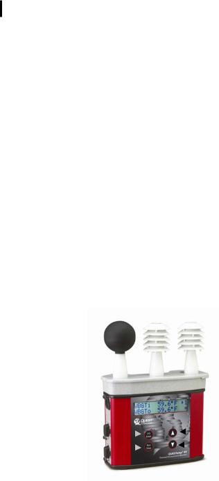
Figure 1-1: QUESTempº 44/46 in a thermal environment
QUESTempº Models
QUESTempº 44 and QUESTempº 46 both measure and calculate the dry bulb, wet bulb, globe, WBGT indoors, WBGT outdoors, relative humidity, and Heat Index or Humidex.
With the QUESTempº 46, you have the capability to measure stay times in order to manage work/rest regimens. Guidance is based on the screening criteria for heat stress as defined in the ACHIH TLV Handbook, U.S. Navy PHEL charts, U.S. Navy/Marine Corp. Ashore Flag system, and EPRI Action Limits.
An additional feature with the QUESTempº 46 is an optional detachable probe for measuring air velocity to determine appropriate levels of indoor thermal comfort monitoring.
Getting Started
2 Getting Started
Up and Running overview
Getting Started
Up and Running overview
1.Place the QUESTempº 44/46 in the work area in a safe location approximately 3.5 feet off the ground.
2.Turn the unit On. If the battery voltage displayed during the power-on sequence is less than or equal to 6.4 volts, replace or recharge the batteries.
3.Be aware that the sensors require 10 minutes to stabilize to a new environment.
4.In the main menu, View will be selected (an indicator arrow denotes the selected menu). Press the I/O Enter key to select.
5.Press the Run/Stop key to begin datalogging. Use the arrow keys to set the display to the desired items.
Keypad Operation
The unit operates using a keypad with 4 keys. The I/O Enter key responds when the key is released while all other keys respond when the key is pressed.
3 Getting Started
Keypad Operation
I/O Enter key
The unit turns on with a single key press. The unit turns off by holding the key down while a countdown of 3-2-1 occurs in the lower right corner of the display. This key is also used to select a mode (such as Setup or View) or enter setup changes.
Pressing and releasing the key while viewing temperatures causes the display to view the next available sensor bar (indicated in the upper right corner of the display).
Up Arrow key
Changes items appearing in the display. Scrolls up.
Down Arrow key
Changes items appearing in the display. Scrolls down.
Run Stop key
From the menu or view modes, pressing this key starts or stops the run mode. Pressing this key will exit the setup, print or reset modes.
Escaping or moving back one screen
If you are in the setup, print, reset, or calibration screens, you can press Run/Stop key to escape or move back one screen.
|
|
|
|
|
|
Up arrow key |
I/O Enter key |
|
|||||
|
|
|
|
|
Down arrow key |
|
Run/Stop key |
|
|
|
|
|
|
|
|
|
|
|
||
|
|
|
|
|
|
|
|
|
|
|
|
|
|
|
|
|
|
|
|
|
Figure 1-2: Keypad explained
4 Getting Started
Turning on/off and basic operation
Turning on/off and basic operation
To quickly get you started with the QUESTempº 44/46, the following section explains how to turn on the instrument, run, and stop your session.
1.Press the I/O Enter key to turn on. Proceeding the model and revision information displayed on the screen, the main menu will appear.
VIEW PRINT SETUP RESET
Indicator arrow
Indicates the selected menu option. Then press I/O enter to select or press up/down arrows to select another option
Figure 1-3: Main menu of the QTº44/46
2.Press the I/O Enter key (when view is selected) to access the measurement screens.
•(The Wet and Dry measurements screen will display. See Figure 1-6, page 10 for an example).
3.To view different measurements, press the Up or Down arrow key to toggle through the views.
NOTE: There are 5-user selectable languages included in the QUESTempº 44/46. If you see the fields such as Wet, Dry, WBGTi, and WBGTo this indicates the measurements are displaying in English.
•To display an alternative language, select Setup from the main menu. Press the Down arrow repeatedly until “English” (or the appropriate language) appears. Then repeatedly press the I/ O enter key to toggle through the languages. Once selected, all menus and measurement screens will change to the selected language. To return to the main menu, press the Run/Stop key.
4.To return to the main menu, press and hold the I/O Enter key (3, 2, 1 countdown will appear) and the main menu will display.
a.To select an option on the main menu, press the up or down arrow until an arrow appears directly in front of the appropriate menu selection and then press I/O enter key.
5.To power off, press and hold the I/O enter key from the main menu.
Placing the QUESTempº 44/46 on the job site
The QUESTempº 44/46 should be placed at a height of 3.5 feet (1.1m) for standing individuals or 2 feet (.6m) for seated individuals. Tripod mounting is recommended to get the unit away from anything that might block radiant heat or airflow. A 1/4"x 20 threaded bushing on the bottom of the instrument allows mounting to a standard photographic tripod. Do not stand close to the unit during sampling.
Before datalogging, allow ten minutes for the sensors readings to stabilize.
Sensors
5 Sensors
About the sensor bar
Sensors
About the sensor bar
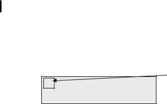
The sensor bar, on the QTº 44/46, is calibrated to its specific instrument and is not interchangeable with other QTº 44/46. The instrument has a sensor bar label which includes the serial number of the instrument and a sensor bar number. (This is indicated in the diagram below.) 
Serial number and sensor bar number label
Figure 1-4: About sensor bar and serial number
Globe Thermometer
The globe thermometer (left position) gives an indication of the radiant heat exposure on an individual due to either direct sunlight or hot objects in the environment. This is accomplished by placing a temperature sensor inside a blackened copper sphere and measuring the temperature rise. The WBGT index is based on the response of a 6 inch diameter globe. The QUESTemp uses a 2 inch diameter globe for a faster response time. The temperature of the 2 inch globe is correlated to match that of a 6 inch globe.
Waterless Wetbulb Sensor and Relative Humidity Sensor
The relative humidity sensor (middle position) is used to calculate the Waterless Wetbulb from a combination of dry bulb temperature, humidity and wind speed measurements. The Waterless Wetbulb is used to calculate an estimated WBGT value. (Please see “Waterless Wetbulb” on page 7 for more details.)
Dry Bulb Thermometer
The dry bulb thermometer (right position) measures the ambient air temperature. This measurement is used in the outdoor WBGT calculation when a high solar radiant heat load may be present. The series of white plates surrounding the
sensor shield it from radiant heat. |
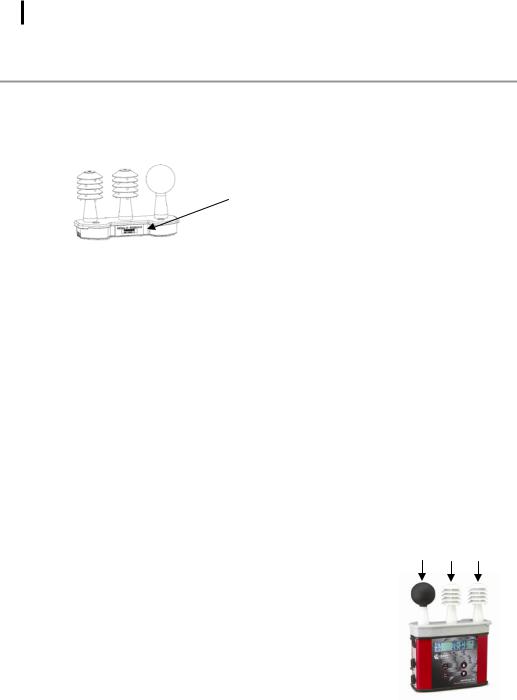
A |
B C |
|
A.Globe thermometer
B.Relative humidity sensor
C.Dry bulb thermometer
Figure 1-5: Sensors identified
|
|
Remote |
6 |
Remote, Sensors 2 and 3 |
Sensors |
|
Tri-sensor weighted average |
|
Remote, Sensors 2 and 3
The top sensor bar (sensor 1) may be removed from the instrument and used through a remote cable. Shelter the instrument and remote the sensor bar if the measured environment is expecting heavy rain or if temperatures are above 60°C.
The sensor 2 and sensor 3 jacks on the side of the instrument allow simultaneous monitoring of up to three sensor arrays using connecting cables.
Cable lengths of up to two hundred feet (61 meters) may be used without a decrease in accuracy provided the environment does not contain strong electromagnetic fields. The data from these arrays may be viewed separately or combined into a weighted average WBGT reading per ISO 7243. Change the displayed sensor bar by pressing and releasing the enter key. The upper right corner of the display shows the current sensor bar. 1 refers to the top sensor bar, 2 and 3 are labeled on the side of the unit, W indicates the weighted average which only appears if a WBGT is displayed and all three of the sensor bars are attached.
Tri-sensor weighted average
Per the recommendations outlined in ISO 7243: 1989, when the temperature in the space surrounding a worker is not uniform, it is necessary to determine the WBGT index at three heights corresponding to the worker's ankles, abdomen and head and perform a weighted average on those values. It is computed using the formula:
WBGTw = (WBGT head + (2 x WBGT abdomen) + WBGT ankles)/4
The QUESTemp° 44/46 always assigns the top sensor bar the double weighting. This calculation is shown if a WBGT display has been selected and if 3 sensor sets are connected.

Measurements
7Measurements
Waterless Wetbulb
Measurements
The QUESTemp° 44/46 data logging area heat stress monitor directly senses three parameters: dry bulb temperature (DB), globe temperature (G), and relative humidity (RH).
It computes the wet bulb (WB), the Wet Bulb Globe Temperature (WBGT), stay times for four possible indices, and the Heat Index (HI) or the Canadian Humidex. Using inputs on the side of the instrument, two additional sensor arrays can monitor up to three locations simultaneously.
On the QUESTempº 46 model, you can measure airflow, in meters per second, by plugging an optional hot wire anemometer sensor into a side jack on the unit.
Determine thermal comfort indices, Predicted Mean Vote (PMV) and Predicted Percent Dissatisfied (PPD), using Detection Management Software (DMS).
Waterless Wetbulb
The Waterless Wetbulb is an estimated measurement using the % of Relative Humidity, Dry Bulb Temperature, and Globe Bulb Temperature to determine the psychrometric wetbulb. The psychrometric wetbulb value is adjusted based on airflow to provide the waterless wetbulb estimate.
Computing Waterless wetbulb and wind speed
When computing the waterless wetbulb, you can increase accuracy by setting the airflow to the current environments wind speed. The recommended airflow setting for an indoor environment is 0.3 m/s unless otherwise determined with an air-probe measurement (available only on the QTº46 model). The recommended setting for outdoor environment is 2.0 m/s.
NOTE: To convert wind speed from miles/hour to meters/sec use the following formula:
•Miles/hour * .447 = meters/sec. (Example: If the average wind speed is 5mph, then enter 5*.447 = 2.2 meters/sec.)
If you are using the QUESTempº46 with the Air Probe attached, you would not set the airflow setting. (It will automatically calculate with the current reading.)
Please see “Setup for Waterless Wetbulb measurement” on page 11 for details on setting the Airflow.

8 Measurements
WetBulb Globe Temperature
WetBulb Globe Temperature
The WBGT is a weighted average of the three temperature sensors using the following formulas:
•WBGT (indoor) = 0.7WB + 0.3G (denoted as “WBGTi” on the display)
•WBGT (outdoor) = 0.7WB + 0.2G + 0.1DB (denoted as “WBGTo” on the display)
The resulting WBGT values can then be compared to indices of work-rest regimens (stay times) based upon work loads.
Stay Times/Rest Times (QTº46 only)
Stay times represent how long a worker should be able to safely work under heat stress conditions. Select one of four indices for displaying and printing from the unit: ACGIH Stay Times, NAVY PHEL’s, U.S. Navy/Marine Corp. Ashore Flag Conditions, or EPRI Action Limits. Refer to Appendix B for more information on the indices.
Heat Index/Humidex
The Heat Index is determined using the dry bulb temperature and relative humidity. Based upon charts available from the U.S. National Weather Service, Heat Index represents how an average person feels relative to climate conditions. For a given temperature, the higher the humidity, the higher the heat index.
The Heat Index is defined over a temperature range of 70°F - 120°F (21°C - 49°C) and a relative humidity range of 30% - 99%. Outside of this range, the instrument will show dashes in the display for the Heat Index.
The Humidex, used primarily in Canada, works on the same concept as the Heat Index. The values are slightly different. The Humidex is defined over a temperature range of 70°F - 109°F (21°C - 43°C) and a relative humidity range of 20% - 99%. Outside of this range, the instrument will show dashes in the display for the Humidex.
Airflow
The QUESTemp° 46 measures airflow if Quest’s Air Probe accessory is used. The Air Probe uses an omni-directional anemometer sensor that measures air flow between 0 and 20 meters per second in 0.1m/s increments. Please see “Airflow Functionality”, page 21 for more details.

9 Measurements
Thermal Comfort
Thermal Comfort
Thermal comfort readings for indoor environments are a benefit of Detection Management Software (DMS) and are not displayed or printed from the instrument directly. Readings are derived from the dry bulb, relative humidity, mean radiant temperature, airflow, and user entered parameters of clothing, metabolic rate and external work.
Thermal comfort indices, Predicted Mean Vote (PMV) and Predicted Percent Dissatisfied (PPD), help predict the thermal satisfaction level of a person with their indoor environment. The PMV is a rating scale of +3 to -3 where +3 is much to warm, -3 is much too cool, and 0 is thermally neutral. The PPD reflects what percent of people in a given location would be dissatisfied with their thermal surroundings.
The formulas used by DMS to derive the PMV and PPD come from the international standard ISO 7730 “Moderate thermal environments - Determination of the PMV and PPD indices and specification of the conditions for thermal comfort”.
Loading...