


Instructions and Parts List
AccuGlideTM 2+
STD 2 Inch
Upper and Lower
Taping Heads
Type 10500
Serial No._____________________________________
For reference, record taping head(s) serial number(s) here.
3M Industrial Adhesives and Tapes
3M Center, Building 220-5E-06
St. Paul, MN 55144-1000
Important Safety
Information
BEFORE INSTALLING OR OPERATING THIS EQUIPMENT
Read, understand, and follow all safety and operating instructions.
Spare Parts
It is recommended you immediately order the spare parts listed in the "Spare Parts/Service Information" section. These parts are expected to wear through normal use, and should be kept on hand to minimize production delays.
AccuGlide™ is a Trademark of 3M, St. Paul, MN 55144-1000
Litho in U.S.A
© 3M 2005 44-0009-2036-1(A)

Replacement Parts and Service Information
To Our Customers:
This is the 3M-Matic™/AccuGlide™/Scotch® equipment you ordered. It has been set up and tested in the factory with Scotch® tapes. If technical assistance or replacement parts are needed, call or fax the appropriate number listed below.
Included with each machine is an Instructions and Parts List manual.
Technical Assistance:
3M-Matic™ Helpline – 1-800/328 1390. Please provide the customer support coordinator with the machine number, machine type/model and serial number. If you have a technical question that does not require an immediate response, you may Fax it to 651-736-7282.
Replacement Parts and Additional Manuals
Order parts by part number, part description and quantity required. Also, when ordering parts and/or additional manuals, include machine name, number and type. A parts order form is provided at the back of this manual.
3M/Tape Dispenser Parts |
|
241 Venture Drive |
1-800/344 9883 |
Amery, WI 54001-1325 |
FAX# 715/268 8153 |
Minimum billing on parts orders will be $25.00. Replacement part prices available on request. $10.00 restocking charge per invoice on returned parts.
Note : Outside the U.S., contact the local 3M subsidiary for parts ordering information.
3M Industrial Adhesives and Tapes
3M Center, Building 220-5E-06
St. Paul, MN 55144-1000
"3M-Matic", "AccuGlide" and “Scotch” are trademarks of 3M, St. Paul, Minnesota 55144-1000
Printed in U.S.A.
© 3M 2005 44-0009-1851-4(F)

Replacement Parts and Service Information
To Our Customers:
This is the 3M-Matic™/AccuGlide™/Scotch® equipment you ordered. It has been set up and tested in the factory with Scotch® tapes. If any problems occur when operating this equipment and you desire a service call or phone consultation, call, write or fax the appropriate number listed below.
Included with each machine is an Instructions and Parts List manual.
SERVICE, REPLACEMENT PARTS AND ADDITIONAL MANUALS
AVAILABLE DIRECT FROM:
Order parts by part number, part description and quantity required. Also, when ordering parts and/or additional manuals, include machine name, number and type.
3M Industrial Adhesives and Tapes
3M Center, Building 220-5E-06
St. Paul, MN 55144-1000
"3M-Matic", "AccuGlide" and “Scotch” are trademarks of 3M, St. Paul, Minnesota 55144-1000
Printed in U.S.A.
© 3M 2005 44-0009-1852-2(E)

Instruction Manual |
|
AccuGlide™ 2+ STD 2 Inch |
|
Upper and Lower Taping Heads |
|
Type 10500 |
|
Table of Contents |
Page |
Equipment Warranty and Limited Remedy ............................................................................................... |
ii |
Taping Head Contents .............................................................................................................................. |
ii |
Intended Use ............................................................................................................................................ |
1 |
Important Safeguards ............................................................................................................................... |
2 |
Specifications ............................................................................................................................................ |
4 - 5 |
Dimensional Drawing ..................................................................................................................... |
5 |
Installation ................................................................................................................................................. |
6 |
Receiving and Handling ................................................................................................................. |
6 |
Installation Guidelines ................................................................................................................... |
6 |
Tape Leg Length ........................................................................................................................... |
6 |
Tape Width Adjustment ................................................................................................................. |
6 |
Operation .................................................................................................................................................. |
7 - 9 |
Tape Loading – Upper Taping Head ............................................................................................. |
8 |
Tape Loading – Lower Taping Head ............................................................................................. |
8 - 9 |
Maintenance ............................................................................................................................................. |
10 - 11 |
Blade Replacement ....................................................................................................................... |
10 |
Blade Guard .................................................................................................................................. |
10 |
Blade Oiler Pad ............................................................................................................................. |
10 |
Cleaning ........................................................................................................................................ |
11 |
Applying/Buffing Roller Replacement ............................................................................................ |
11 |
Adjustments .............................................................................................................................................. |
12 - 14 |
Tape Latch Alignment.................................................................................................................... |
12 |
Tape Drum Friction Brake ............................................................................................................. |
12 |
Applying Mechanism Spring .......................................................................................................... |
13 |
One-Way Tension Roller ............................................................................................................... |
13 |
Tape Leg Length ........................................................................................................................... |
14 |
Leading Tape Leg Length Adjustment ............................................................................ |
14 |
Changing Tape Leg Length From 70 to 50 mm [2-3/4 to 2 Inch].................................... |
14 |
Troubleshooting ........................................................................................................................................ |
15 - 16 |
Troubleshooting Guide .................................................................................................................. |
15 - 16 |
Spare Parts/Service Information ............................................................................................................... |
17 |
Recommended Spare Parts ........................................................................................................ |
.. 17 |
Replacement Parts and Service.................................................................................................... |
17 |
Replacement Parts Illustrations and Parts List ................................................................ |
Yellow Section 18 - 35 |
i

Equipment Warranty and Limited Remedy: THE FOLLOWING WARRANTY IS MADE IN LIEU OF ALL OTHER WARRANTIES, EXPRESS OR IMPLIED, INCLUDING, BUT NOT LIMITED TO, ANY IMPLIED WARRANTY OF MERCHANTABILITYORFITNESSFORAPARTICULARPURPOSEANDANYIMPLIEDWARRANTYARISINGOUT
OF A COURSE OF DEALING, CUSTOM OR USAGE OF TRADE:
3M sells its AccuGlide™ 2+ STD 2 Inch Upper and Lower Taping Heads, Type 10500 with the following warranty:
1.The Taping Head blade, springs and rollers will be free from defects in material and manufacture for ninety (90) days after delivery.
2.All other Taping Head parts will be free from defects in material and manufacture for three (3) years after delivery.
If any part is defective within this warranty period, your exclusive remedy and 3M’s and seller’s sole obligation shall be, at 3M’s option, to repair or replace the part. 3M must receive actual notice of any alleged defect within a reasonable time after it is discovered, but in no event shall 3M have any obligation under this warranty unless it receives such notice within five (5) business days after the expiration of the warranty period. All notices required hereunder shall be given to 3M solely through the 3M-Matic™ Helpline (800-328-1390). To be entitled to repair or replacement as provided under this warranty, the part must be returned as directed by 3M to its factory or other authorized service station designated by 3M. If 3M is unable to repair or replace the part within a reasonable time after receipt thereof, 3M, at its option, will replace the equipment or refund the purchase price. 3M shall have no obligation to provide or pay for the labor required to remove any part or equipment or to install the repaired or replacement part or equipment. 3M shall have no obligation to repair or replace those parts failing due to normal wear, inadequate or improper maintenance, inadequate cleaning, nonlubrication, improper operating environment, improper utilities, operator error or misuse, alteration or modification, mishandling, lack of reasonable care, or due to any accidental cause.
Limitation of Liability: Except where prohibited by law, 3M and seller will not be liable for any loss or damage arising from this 3M equipment, whether direct, indirect, special, incidental, or consequential, regardless of the legal theory asserted, including breach of warranty, breach of contract, negligence, or strict liability.
Note: TheforegoingEquipmentWarrantyandLimitedRemedyandLimitationofLiabilitymaybechangedonlybyawritten agreement signed by authorized representatives of 3M and seller.
Taping Head Contents
AccuGlide™ 2+ Stainless Steel 2 Inch Upper and Lower Taping Heads consist of:
Qty. |
Part Name |
|
|
1 |
Taping Head Assembly |
1 |
Tape Drum and Bracket Assembly |
1 |
Hardware and Spare Parts Kit |
1 |
Threading Tool |
|
|
AccuGlide™, Scotch™, and 3M-Matic™ are Trademarks of 3M, St. Paul, Minnesota 55144-1000
ii
Intended Use
The intended use of the AccuGlide™ 2+ STD 2 Inch Upper and Lower Taping Heads is to apply a "C" clip of Scotch® pressure-sensitive film box sealing tape to the top and/or bottom center seam of regular slotted containers.
These taping heads are incorporated into most standard 3M-Matic™ case sealers. The compact
size and simplicity of the taping head also makes it suitable for mounting in box conveying systems other than 3M-Matic™ case sealers. This includes replacement of other types of taping, gluing or stapling heads in existing case sealing machines. The AccuGlide™ 2+ STD Taping Heads have been designed and tested for use with Scotch® pressuresensitive film box sealing tape.
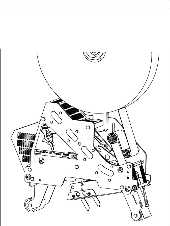
AccuGlide™ 2+ STD 2 Inch Upper Taping Head, Type 10500
1

Important Safeguards
This safety alert symbol identifies important safety messages in this
manual. READ AND UNDERSTAND THEM BEFORE INSTALLING OR OPERATING THIS EQUIPMENT.
Explanation of Signal Word Consequences
WARNING: Indicates a potentially hazardous situation, which, if not avoided, could result in death or serious injury and/or property damage.
CAUTION: Indicates a potentially hazardous situation, which, if not avoided, may result in minor or moderate injury and/or property damage.
 WARNING
•To reduce the risk associated with mechanical hazards:
−Read, understand and follow all safety and operating instructions before operating or servicing the case sealer
−Allow only properly trained and qualified personnel to operate and/or service this equipment
•To reduce the risk associated with shear, pinch, and entanglement hazards:
−Turn air and electrical supplies off on associated equipment before performing any adjustments, maintenance, or servicing the taping heads
−Never attempt to work on the taping head or load tape while the box drive system is running
•To reduce the risk associated with sharp blade hazards:
−Keep hands and fingers away from tape cutoff blades under orange blade guards. The blades are extremely sharp
 CAUTION
•To reduce the risk associated with muscle strain:
−Use proper body mechanics when removing or installing taping heads that are moderately heavy or may be considered awkward to lift
•To reduce the risk associated with impact hazards:
−Place the taping head on a smooth level surface when maintaining or servicing this equipment
2
Important Safeguards (Continued)
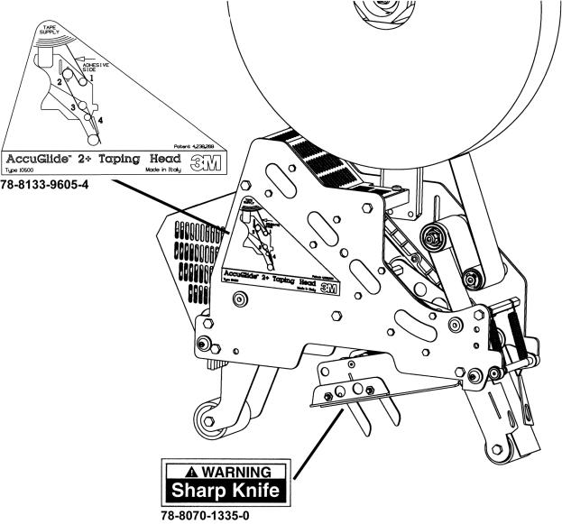
Important – In the event the following safety labels are damaged or destroyed, they must be replaced to ensure operator safety. See "Replacement Parts Illustrations and Parts Lists" for label part numbers.
78-8133-9606-2 Tape Threading Label (Not shown)
Figure 1-1 – Replacement Labels/3M Part Numbers
3

Specifications
1.Tape:
For use with Scotch® pressure-sensitive film box sealing tapes.
2.Tape Width:
36 mm or 1-1/2 inches minimum to 48 mm [2 inches] maximum.
3.Tape Roll Diameter:
Up to 405 mm [16 inches] maximum on a 76.2 mm [3 inch] diameter core. (Accommodates all system roll lengths of Scotch® film tapes.)
4.Tape Application Leg Length - Standard:
70 mm ± 6 mm [2-3/4 inches ±1/4 inch]
Tape Application Leg Length - Optional:
50 mm ± 6 mm [2 inches ± 1/4 inch] (See "Adjustments – Tape Leg Length.")
5.Box Size Capacities:
For use with center seam regular slotted containers.
Minimum |
Maximum |
Length – 150 mm [6 inches]
Height – 120 mm [4-3/4 inches] (most “3M-Matic” Case Sealers) 90 mm [3-1/2 inches] (with optional 2 inch leg length)
Width – 115 mm [4-1/2 inches]
Unlimited
Limited by
Case Sealer
When upper and lower taping heads are used on “3M-Matic” case sealers, refer to the respective instruction manual specifications for box weight and size capacities.
6. Operating Rate:
Conveyor speeds up to 0.40 m/s [80 FPM] maximum.
7.Operating Conditions:
Use in dry, relatively clean environments at 5° to 40° C [40° to 105° F] with clean dry boxes.
Important – Taping heads should not be washed down or subjected to conditions causing moisture condensation on components.
8. Taping Head Dimensions:
Length |
– |
457 mm [18 inches] |
Height |
– |
560 mm [22 inches] (with tape drum) |
Width |
– |
105 mm [4-1/8 inches] (without mounting spacers) |
Weight |
– |
Packaged: 7.7 kg [17 lbs.] Unpackaged: 6.7 kg [15 lbs.] |
4

Specifications (Continued)
Figure 2-1 – Dimensional Drawing
5
Installation
 WARNING
•To reduce the risk associated with sharp blade hazards:
−Keep hands and fingers away from tape cutoff blades under orange blade guards. The blades are extremely sharp
Receiving And Handling
After the taping head assembly has been unpackaged, examine the unit for damage that might have occurred during transit. If damage is evident, file a damage claim immediately with the transportation company and also notify your 3M Representative.
Installation Guidelines
The taping head assembly can be used in converting existing or in custom made machinery.
It can be mounted for top taping or bottom taping. Refer to "Box Size Capacities," as well as Figure 2-1 in the Specifications section, for the following points in making such installations:
 CAUTION
• To reduce the risk associated with muscle strain:
−Use proper body mechanics when removing or installing taping heads that are moderately heavy or may be considered awkward to lift
Important – Always conduct a hazard review to determine appropriate guarding requirements when the installation is in an application other than 3M-Matic(TM) equipment
1.The box conveying system must positively propel the box in a continuous motion, not exceeding 0.40 m/s [80 feet per minute], past the taping head assembly since the box motion actuates the taping mechanism.
2.If a pusher or cleated conveyor is being used, steps should be taken in the conveyor design to prevent the pusher from contacting the applying or buffing roller arms resulting in damage to the taping head.
3.Figure 2-1 illustrates the typical mounting relationship for opposing taping head assemblies to allow taping of box heights down to 90 mm [3- 1/2 inches]. To tape box heights down to 70 mm [2-3/4 inches], the taping heads must be completely staggered so only one tape seal is being applied at one time.
Note – AccuGlide™ 2+ STD Upper Taping Head is supplied with a buffing arm guard. Adjustments to this guard may be required to install the taping head into some older design 3M-Matic™ case sealers.
4.Mounting studs are provided with the taping head, but special installations may require alternate means for mounting.
5.Box hold-down or guide skis should be provided and the taping head mounted so that the side plates are 6 mm [1/4 inch] maximum away from the ski surface on which the box rides.
Tape Leg Length
Taping heads are factory set to apply standard 70 mm [2-3/4 inch] tape legs. The heads can be converted to apply 50 mm [2 inch] tape legs if
desired but both upper and lower heads must be set to apply the same tape leg length. See "Adjustments
– Changing Tape Leg Length From 70 to 50 mm [2-3/4 to 2 Inches]."
Also, the conveyor speed at which the product moves through the taping heads, affects the leading and trailing tape leg length. See "Adjustments section – Leading Tape Leg Length Adjustment."
Tape Width Adjustment
Taping heads are factory set to apply 48 mm [2 inch] wide tape. If it is necessary to align the tape or to apply narrower tapes, refer to "Adjustments – Tape Web Alignment" for set-up procedure.
6
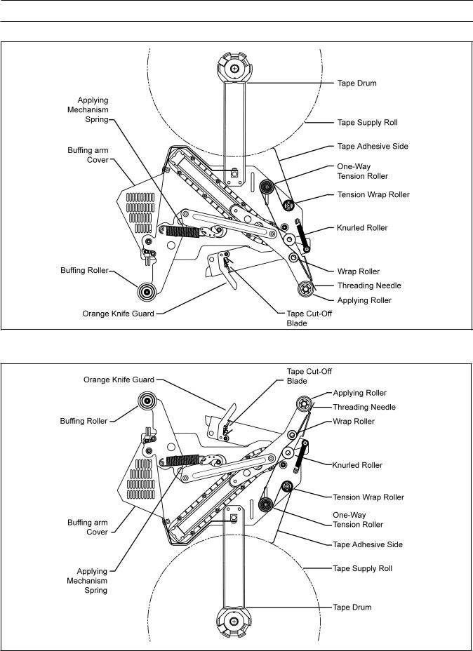
Operation
Figure 3-1 – Taping Head Components/Threading Diagram, Upper Head (Left Side View)
Figure 3-2 – Taping Head Components/Threading Diagram – Lower Head (Left Side View)
7
 Loading...