

Model 2100 (4100)
Overhead Projector
Service Manual
(Order the M2100 Illustrated Parts Breakdown separately - Stock # 78-6970-4936-5)
78-6970-1335-3 9/92
Visual Systems Division
3M Austin CenterBuilding
A145-5N-01
Austin, TX 78726-9000

MODEL 2100 OVERHEAD PROJECTOR
TABLE OF CONTENTS
Technical Support Hotline - 1-800-328-1371 (U.S. & Canada)
TITLE PAGE NUMBER
Section 1 - Introduction.................................................................................1-1
Specifications..............................................................................1-1
Principles of Operation................................................................1-3
- Optics.......................................................................................1-3
- Cooling.....................................................................................1-3
Section 2 - Operation and Maintenance........................................................2-1
Set Up Procedure.......................................................................2-1
Lamp Management System........................................................2-3
Cleaning......................................................................................2-4
- Cleaning Stage and Fresnel Lens.............................................2-4
- Mirrors......................................................................................2-4
Lubrication..................................................................................2-5
Section 3 - Troubleshooting...........................................................................3-1
Section 4 - Adjustments................................................................................4-1
General.......................................................................................4-1
Tools Required............................................................................4-1
Projector Check-out Facilities......................................................4-1
Optical Alignment........................................................................4-3
- Square Image...........................................................................4-3
- Focus Mechanism.....................................................................4-4
- Aligning the Fresnel Lens.........................................................4-4
Color Tuning Cable......................................................................4-5
Post (Folding)..............................................................................4-6
Lampchanger Cable....................................................................4-6
Section 5 - Electrical Diagrams.....................................................................5-1
Section 6 - Disassembly/Re-assembly..........................................................6-1
Projection Head Assembly (Doublet)..........................................6-1
Projection Head Assembly (Triplet).............................................6-1
Top Cover Assembly...................................................................6-1
Fresnel Lens...............................................................................6-1
Stage Glass................................................................................6-2
Focusing Assembly.....................................................................6-2
Condenser Lens.........................................................................6-3
Section 7 - Illustrated Parts Breakdown.........................................................7-1
(Published separately - Stock # 78-6970-4936-5)
9/92
MODEL 2100 OVERHEAD PROJECTOR
SECTION 1 INTRODUCTION
This service manual contains servicing instruction, troubleshooting guide,
adjustments, electrical diagrams, assembly/dis-assembly of parts and the
illustrated parts list.
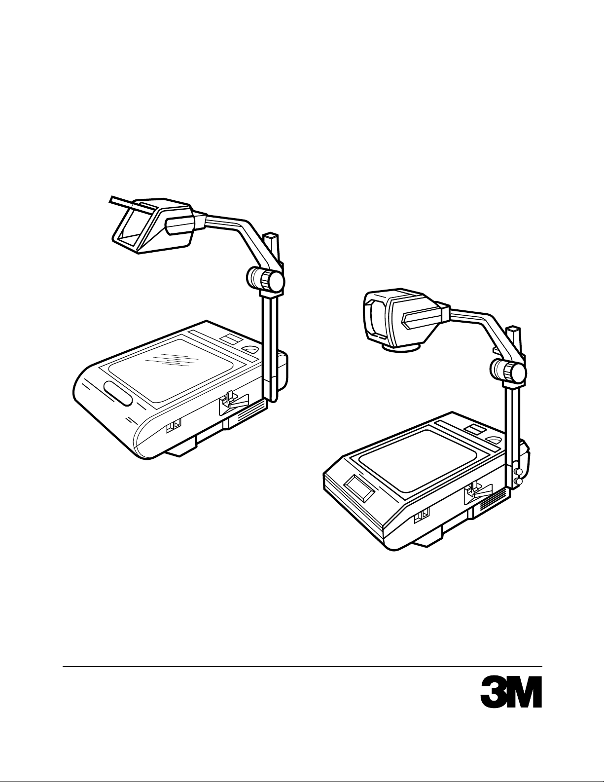
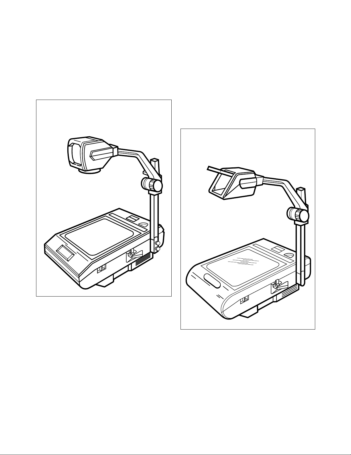
ANGULAR BODY
(2130/4130, 2140/4140, 2160, 2170)
ROUND BODY
(2150/4150, 2180)
SPECIFICATIONS
Physical
Width - 15.25" (387mm)
Depth - 20.25" (514mm) (Post in upright position)
- 26.25" (667mm) (Post in folded position)
Height - 7.75" (197mm) (Body)
- 30.75" (781mm) (Maximum, top of head)
Weight - 22 lbs. (10.0 Kg) 2180
- 25 lbs. (11.3 Kg) 2130, 2140, 2150, 2160, 2170, 4130, 4140, 4150
9/92
1-1
MODEL 2100 OVERHEAD PROJECTOR
1-2
9/92

MODEL 2100 OVERHEAD PROJECTOR
Electrical
2130/2140/2150
2160/2170/2180 2160/2170/2180
4130/4140/41 50
Voltage
Frequency
Current Rating
Power Cord
Agency Approval
120/127/VAC
60HZ
3.0 Amps
14-1/2' (4.4mm)
UL, CSA
100VAC
50/60HZ
3.6 Amps
14-1/2' (4.4mm)
-------
220/230/240VAC
50HZ
1.7 Amps
14-1 /2' (4.4mm)
VDE, NEMKO,
SETI
Fuse
-------
F4 Amp - 250 Volt
SEMKO, SEV
F4 Amp - 250 Volt
Mechanical
Safety interlock: Shuts off power to the projector when the top cover assembly is opened.
Safety thermostat: Cuts power to the lamp if the projector exceeds safe operating
temperature.
Color tuning knob: Allows projector to be easily color tuned for any screen size
1.0m x 1.0m (40" x 40") to 2.8m x 2.8m (110" x 110").
Projection Head Tilt - 0° - 20° (All Heads)
Lamp Changer - when lamp burns out, switch to standby lamp.
Optical
Lamp: ANSI Code FNT, 24 Volt, 275 Watt
Lamp Life: 75 Hours
2130/2140/2150 2160/2170/2180
4130/41 40/4150
Illumination: 2000 lumens typical; 2100 lumens typical;
1800 lumens minimum;1900 lumens minimum;
Mirrors: Chassis mirror is second surface high reflective type. (After serial no. 435242)
Projection mirror is front surface high reflective type.
2130, 2140, 2160, 2170 2150, 2180
4130/4140 4150
Head, Projection: 355mm (14.0" F.L.) 327mm (12.9" F.L.)
Doublet Triplet - w/focus
293mm (11.5" F.L.) correction
Singlet 330mm (13" F.L.)
After serial no. 411964
2130/21 40/2150 2160/2170/2180
4130/41 40/4150
Stage: 267mm x 267mm 285mm x 285mm
Transmissive (10.5" x 10.5") (11.2" x 11.2")
Aperture
9/92
1-2
MODEL 2100 OVERHEAD PROJECTOR
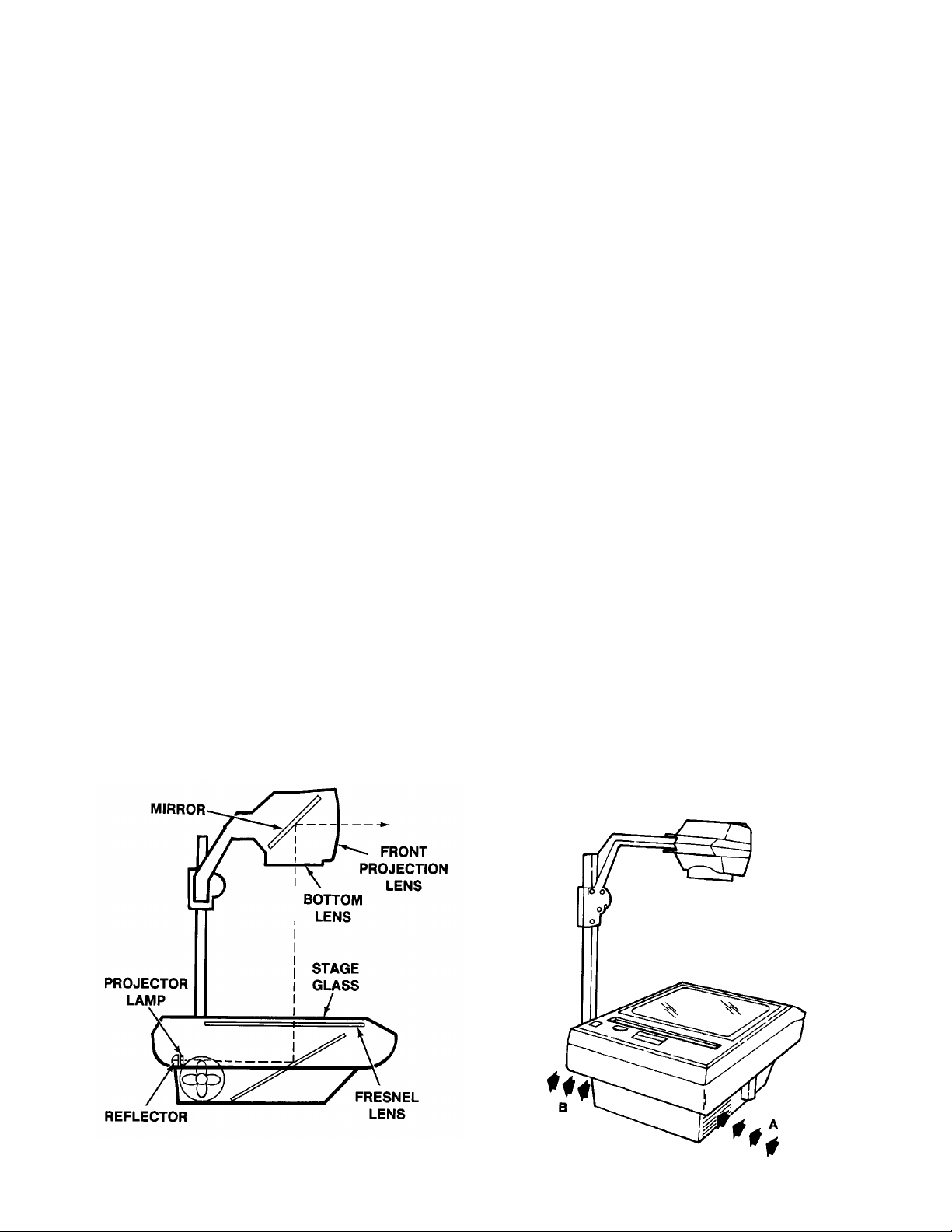
PRINCIPLES OF OPERATION
Optics (See Figure 1-2)
The light source for the Overhead Projector
is 275 watt, 24 volt, Tungsten Lamp listed
as ANSI Code FNT and rated at 75 hours.
An external reflector is needed with this
lamp.
Care should be exercised to prevent
excessive vibration or jarring of the
projector when the lamp is on. The lamp
filament becomes more brittle at the
operating temperature of the projector and
shocks may cause premature failure of the
lamp.
The glass envelope should not be touched
by the fingers when inserting the lamp in
the lampholder. Oils on the skin may
combine with the glass to form blisters
which also will shorten the life of the lamp.
The Fresnel lens, located above the lamp
and directly beneath the projection stage, is
a condensing lens which consists of a
series of concentric rings, each of which
has a surface curvature similar to that of a
thick smooth lens. The Fresnel lens is made
of plastic and may be severely damaged if
the fan is stopped or the paths of cooling air
blocked. Proper alignment and direction of
the Fresnel lens is essential in order to
maintain the resolution and brightness
specifications for the projector.
The stage glass provides a convenient flat
surface for placing transparencies and other
materials to be projected. Because the light
passes through the stage, these projection
materials must be transparent.
There are two (2) different projection head
assemblies available for the projector. One
is an Open Triplet Head with focus
correction which has a triplet lens and front
surface mirror and the second a closed
Doublet Head which has one or two
condensing lens(es) and a front surface
mirror. The projection head is located
directly over the center of the Fresnel Lens.
The projector is focused by raising or
lowering the projection head.
Proper alignment of the optical components
and a clean machine are essential if the
maximum operating capabilities of the
overhead projector are to be realized.
Cleaning and alignment procedures are
discussed in Sections 2 and 4 inclusive.
Cooling (See Figure 1-3)
Cooling of the overhead projector is
accomplished by a motor-driven fan located
next to the lamp housing. The cooling air
enters the projector through opening “A”
and exits through opening “B.” (See Figure
1-3) It’s important that the flow of cooling air
not be restricted either by placing projector
too close to a wall (about one foot
clearance is necessary) or by leaving
foreign objects inside the projector.
1-3
9/92
SECTION 2 - OPERATION AND MAINTENANCE
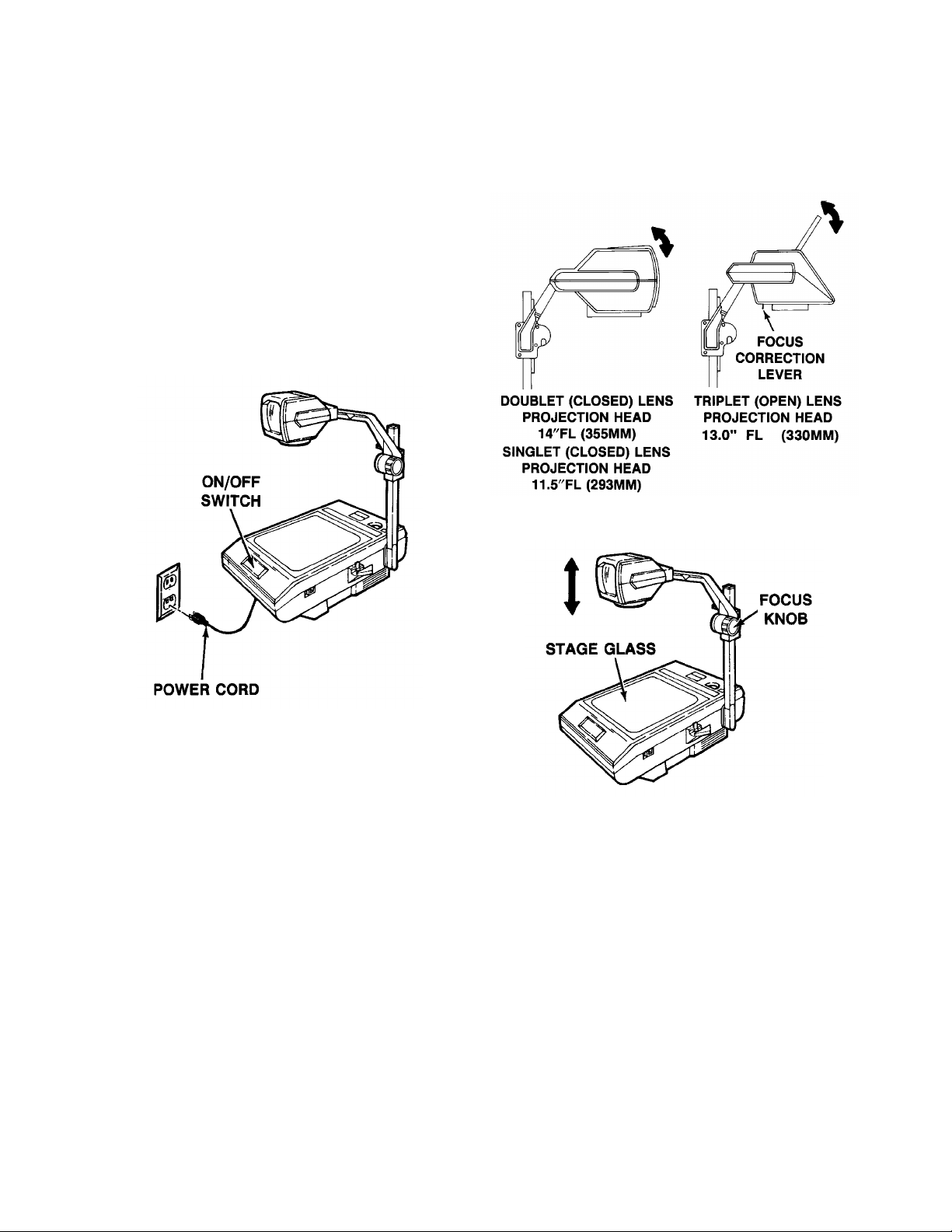
SET UP PROCEDURE
1 . Connect the power cord to a properly
grounded electrical outlet. (Electrical
requirements are listed on the serial plate
located under the base of the projector.)
2. Place the projector on a level surface and
turn the projector on by pushing down on
the ON/OFF switch.
MODEL 2100 OVERHEAD PROJECTOR
CAUTION!
Do not look in the front projection
lens when lamp is on.
3. Adjust the image to the screen
elevation by moving the front
projection lens upward or downward
on the DOUBLET HEAD
ASSEMBLY and the mirror on the
TRIPLET HEAD ASSEMBLY. (See
Figure 2-2)
4. Place a transparency on the stage glass
and focus the projected image by rotating
the Focus Knob. (See Figure 2-3)
5. To maintain top to bottom focus when the
screen is not perpendicular to the
projected image, engage the FOCUS
CORRECTION LEVER located on the
under side of the TRIPLET HEAD
ASSEMBLY using the following
procedure:
NOTE
THE PROJECTION SCREEN
MUST BE IN THE VERTICAL
9/92
POSITION.
2-1
MODEL 2100 OVERHEAD PROJECTOR
A. Pull the mirror down as the FOCUS
CORRECTION LEVER is pushed to
the rear of the head assembly.
B. Raise the mirror back to the original
position and refocus using the FOCUS KNOB.
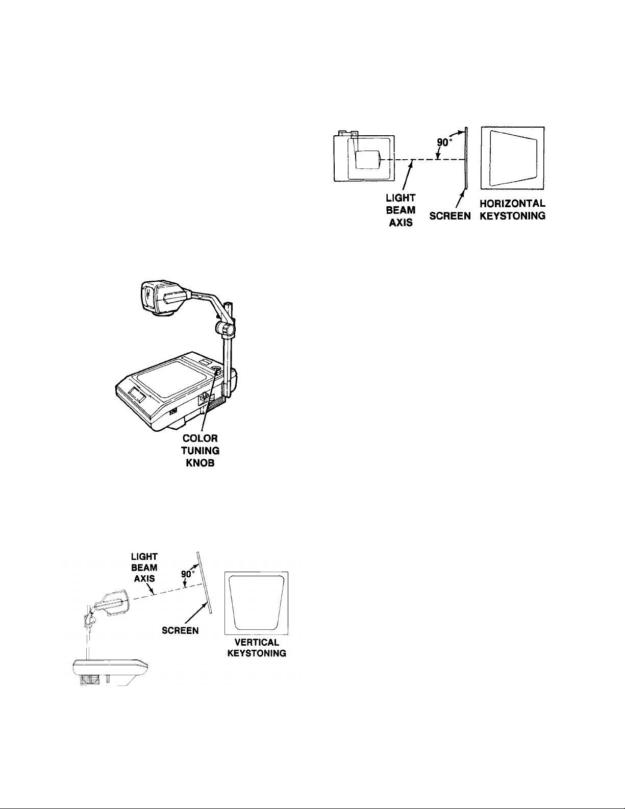
6. Rotate the Color Tuning Knob until
the projected image is free of any
yellow or blue corners.
- To remove blue corners, rotate the
dial counterclockwise.
- To remove yellow corners, rotate the
dial clockwise.
Correct any horizontal keystoning by
moving the projector until it is perpen dicular with the screen.
7. Correct any vertical keystoning by
tilting the screen until it is perpendicular to the light beam axis.
2-2
9/92
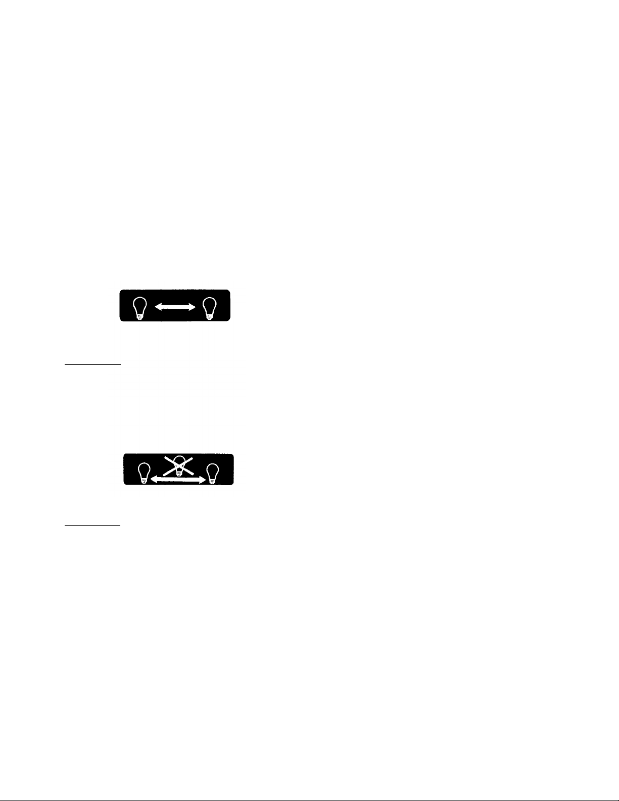
LAMP MANAGEMENT SYSTEM
(Lamp Indicator)
Pertains only to models equipped with lamp
indicators. (2130/4130 - No holes, opaque)
NOTE
When the projector is turned on, the
red X will momentarily light. This is a
characteristic of the projector.
The Lamp Indicator indicates status of
projection lamp as defined on the following
labels:
MODEL 2100 OVERHEAD PROJECTOR
METHOD 1
A red X will appear on the lamp symbol
when that lamp is burned out. Switch to the
standby lamp. The X will continue to light
until the defective lamp is changed.
METHOD 2
A red X will appear between the two lamp
symbols when a lamp is burned out. Switch
to the standby lamp. The X will continue to
light until the defective lamp is changed.
NOTE
The Overhead Projector must remain
on for 2 to 3 minutes after a lamp
burns out. This will allow the fan to
cool the burned-out lamp and
prevent burned fingers. Unplug the
unit before replacing the lamp.
9/92
2-3

MODEL 2100 OVERHEAD PROJECTOR
CLEANING
The optical components of the overhead projector require occasional cleaning to remove
the dust and oil which tends to accumulate
and absorb light. 3M Brand Lens Cleaner
(Part No. 78-6969-7086-6) is recommended.
A small amount of mild detergent in water will
serve as a substitute. Use soft, lint-free cloths,
one to apply the solution and another for
drying.
NOTE
Never use paper lens tissues on
projection lenses as they may damage the lens.
Cleaning Stage Glass and Fresnel Lens
When cleaning the underside of the stage
glass and the top side of the Fresnel Lens,
observe the following steps.
1. Pull the Release Latch and lift the top
cover Top Cover Assembly (See Figure).
2. Remove the Top Cover Assembly by pull-
ing either one of two hinges outward until
the hinge pin is out of the hole. Slide the
complete Top Cover Assembly in the opposite direction to release the second hinge
and lift up and out (See Figure).
3. Loosen the four screws holding the Fresnel
Lens in place.
NOTE: Do not remove the
screws.
4. Turn the retaining clips off to one side.
5. Remove the Fresnel Lens.
6. All surfaces can now be cleaned.
7. Replace all components in reverse order.
Mirrors
2-4
The mirror in the Open Lens Projection
Head of all Model 2100 (4100) projectors
are front surface mirrors and must
cleaned with a cloth and lens cleaner.
Remove any surface dirt on this mirror with
a Camel Hair Brush only.
Prior to serial number 435242 a front surface type Chassis Mirror was used (clean
as above). After serial number 435242, a
second surface high reflective type is used
and may be cleaned with a soft cloth and
lens cleaner.
9/92
NOT
be

LUBRICATION
As needed and upon new parts installation,
lubricate lightly the following area with
Anderol No. 757 Grease (3M Part No. 788000-8079-4).
For reference on the lubricating points, see
the three blow-up parts lists.
MODEL 2100 OVERHEAD PROJECTOR
Focus Assembly
Folding Post Assembly
Lamp Changer Assembly
Before S/N 439180
9/92
Lamp Changer Assembly
After S/N 439180
2-5

MODEL 2100 OVERHEAD PROJECTOR
SECTION 3 - TROUBLESHOOTING
SYMPTOM CHECK CAUSE/SOLUTIONS
Projected image is:
a. Corners of projected image
appear red (brown) or blue.
b. Top, bottom, or sides of
projected image are not
focused.
c. Not as bright as it should
be.
Focus mechanism slips or is
too tight.
- Is lamp of proper type? (See
label on underside of top cover)
- Is lamp properly seated down in
its socket and vertical?
- If unit is equipped with a lamp
changer, is changer lever fully
seated in the number one
position?
- Is lamp of proper type? (See
label on underside of Top
Cover)
- Is lamp properly seated down in
its socket and vertical?
- If unit is equipped with a lamp
changer, is changer lever fully
seated in the number one
position?
- Are any of the optics
components noticeably
"knocked" out of alignment?
- Is lamp of proper type? (See
label on underside of Top
Cover)
- Is lamp properly seated down in
its socket and vertical?
- If unit is equipped with a lamp
changer, is changer lever fully
seated in the number one
position?
- Has another FNT lamp been
tried?
- Focus tension screw needs
adjustment
- Damaged or misadjusted optics
components (requires
realignment of optics).
- Head "knocked" out of
alignment.
- Adjust Color Tuning
- Adjust optics components
(requires realignment of
optics).
- Lamp not seated.
- Reflector
- Condenser
- Replace lamp.
- Damaged or misadjusted optics
components (requires
realignment of optics).
- Corroded wiring connection.
- Wrong lamp on
- Reflector broken/missing
- To tighten, turn screw
counterclockwise. To loosen,
turn clockwise. Add update kit
if required. (see next page)
Lamp does not energize, but
fan motor does energize.
Neither lamp nor fan motor
energizes.
- Is lamp burned out?
- Is lamp of proper type? (See
label on underside of top cover)
- Is lamp properly seated down in
its socket and vertical?
- If unit is equipped with a lamp
changer, is changer lever fully
seated in the number one
position?
- Is power cord plugged into
electrical outlet?
- Is outlet supplying power to
projector?
9/92
- Replace lamp.
- Replace overheat thermostat.
- Replace lamp sensing switch
(only on projectors equipped
with lamp changer).
- Loose or broken wire
connection.
- Defective power supply.
- On-off switch defective.
- Defective interlock switch.
- Loose or broken wire
connection.
- On-off switch out of
adjustment.
- Replace Fuse (if equipped)
3-1

MODEL 2100 OVERHEAD PROJECTOR
TROUBLESHOOTING (continued)
SYMPTOM CHECK CAUSE/SOLUTIONS
Fan motor does not rotate, but
lamp does energize.
Both lamps of units with lamp
changer energize at once.
Projector does not operate
when power switch is
depressed.
On dual lamp projectors,
position of lamp socket does
not change when lamp
changer control is moved.
Top Cover Assembly does not
close completely.
Lamps burn out.
- Is anything blocking rotation of
fan motor?
- Wires crossed and touching?
- Lamp changer switch?
- Projector plugged in?
- Top Cover all the way down?
- Interlock Switch functioning?
- Fuse (if so equipped).
- Loose tension cable.
- Interlock switch out of
alignment?
- Cover latch movement is
restricted?
- High voltage
- Loose or broken wire
connection to motor.
- Defective fan motor.
- Defective lamp sensing switch.
- Defective power cord.
- Defective Interlock Switch.
- Replace Fuse.
- Broken Wire
- Tighten cable. (See Section 4,
adjustments)
- Align interlock switch.
- Disconnected or broken latch
return spring.
- Install Resistor Kit or replace
transformer or change
transformer tap.
Field Kits Available
Focus Knob Slipping
If the projector is below
SN401987, the knob must
also be replaced.
Resistor Kit (120V)
Base Rail Kit (for broken
base rails on lamp module)
Technical Support Hotline - 1-800-328-1371
78-8054-1613-4
78-8054-1614-2
78-8054-1315-6
78-8054-1443-6
78-8054-1615-9
In the U.S & Canada
7:30 - 5:30 CST
Lt. Grey
Charcoal
Tech Service
3-2
9/92
SECTION 4 ADJUSTMENTS
GENERAL
The following section describes the
adjustments that will be necessary to service
the Model 2100 (4100) Overhead Projectors.
TOOLS REQUIRED
A. Screwdriver (standard & phillips)
B. Wrench, open end
C. Pliers, standard
D. Pliers, grip ring
E. Square
F. Torx Driver, #T-15 (for removal of stage
glass) 3M Part Number 26-1005-8317-3
MODEL 2100 OVERHEAD PROJECTOR
PROJECTOR CHECK-OUT FACILITIES
Reliable check-out and optical alignment of the
overhead projectors can be accomplished only
if proper facilities are available. (see Figure)
This requires a permanent viewing screen and
test stand in the dealer’s shop, thus enabling
high check-out standards to be established and
maintained. Service personnel will also find that
the use of permanent test facilities will assure a
better check-out job in considerably less time
than otherwise would be required.
Only two low-cost items are required to provide
proper check-out facilities: a test viewing
screen, 60 by 60 inches, with a flat (nonreflective) white surface; and a bench or test
stand permanently located about 8 feet from
the screen.
The screen should be vertical and can most
easily be provided by applying a flat white paint
to a 60 by 60 inch area of a smooth wall. If a
smooth wall is not available, a piece of
wallboard painted flat white, or a white window
shade of the proper size, can be mounted in
the selected area.
The test stand should be high enough to
provide easy access to all parts of the
Overhead Projector when the projector is
placed on the stand for check-out. An electrical
outlet and a switch should be built into the test
stand to facilitate making electrical connections
to the projector.
Arrangement of Check-out Area
The following steps provide a simple procedure
for setting up the permanent test facilities. It is
particularly important that the projector be
perfectly square with the viewing screen in
order to eliminate the possibility of vertical or
horizontal keystoning. Even the slightest
keystoning will result in unequal focusing of the
projected image at the four corners, and will
especially affect resolution readings.
Therefore, several of the following steps involve
squaring the projected light with the screen.
Permanently locating the test stand and
viewing screen will assure that the proper
relationship, once established, does not
change.
(Continued on the next page)
9/92
4-1

MODEL 2100 OVERHEAD PROJECTOR
1. Select a 60 by 60 inch, smooth area on
one wall. Place a sturdy bench or test
stand about 8 feet from this wall area.
Position the Overhead Projector on the
test stand so that it points toward the
wall.
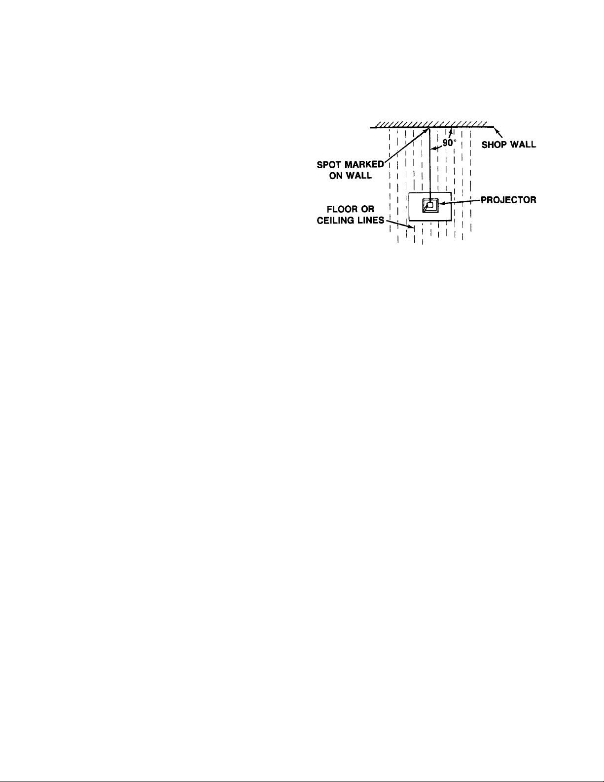
2. Measure the vertical distance from the
floor to the center of the front projection
lens. Following a floor or ceiling line from
the projector to the wall, make a mark on
the wall the same distance from the floor.
4. Using the mark on the wall as a base
point, measure 30 inches up, down, to
the left and to the right. Mark the edges
of the resultant 60-inch square, and paint
the enclosed area a flat white, or cover
the area with a window shade, wallboard
or other substitute viewing screen.
5. Turn the projector on and focus an image
on the screen. Move the projector
forward or backward, maintaining the
image in focus at all times, until the
projected light just fills the 60 by 60 inch
screen. Be sure the image is in focus.
Locating Center of Projection Area
NOTE
If floor or ceiling lines are not
available, stretch a cord or string
from the projection lens to the wall,
and use a carpenter’s square or
other square object to find the point
at which the cord is perfectly
perpendicular to the wall.
3. Mark the position of the stand on the floor
and the projector on the stand so that the
perpendicular relationship of the line from
the projection lens to the wall is not lost
while making subsequent adjustments .
Correct Tilt of Projector
4-2
9/92

OPTICAL ALIGNMENT
Proper alignment of the optical system is
essential for good resolution and uniform
illumination. Poor resolution in one corner and
either red or blue in the corners of the projected
image are indications of poor alignment. The
following components should be checked and
adjusted if necessary before aligning the
overhead projector.
SQUARE IMAGE
A. Set projector on a level table. Project an
image onto a screen or wall. Axis of
beam must be perpendicular to projection
surface.
B. Check to see that side of projected image
are vertical.
C. If the image is not square, remove CAP
and loosen the three (3) Head Fastening
Screws (Doublet Head), and move the
projection head either to the left or right,
forward or backward. When image is
square, tighten the center top screw first,
then the two bottom screws. (See Figure)
MODEL 2100 OVERHEAD PROJECTOR
D. To square the image on the Triplet Head,
remove the two Top Shroud screws and lift
off the Top Shroud. Follow the same
procedure as used on the Doublet Head to
complete adjustment. Replace the Top
Shroud.
9/92
4-3

MODEL 2100 OVERHEAD PROJECTOR
FOCUS MECHANISM
If the projection head does not hold its focus
position, you must adjust focus knob tension or
add focus kit (78-8054-1613-4 (gray), 78-80541614-2 (charcoal).
To adjust:
Turn the Tension Screw counterclockwise to
tighten focus assembly. Turn clockwise if
binding occurs.
ALIGNING THE FRESNEL LENS
When replacing the Fresnel Lens, use the
following procedure:
A. Remove the Top Cover Assembly. (See
Section 2 - Cleaning Stage Glass and
Fresnel Lens, page 2-3)
B. Place the Top Cover Assembly upside
down on a flat, clean surface.
C. With the four (4) corner screws loosened,
stretch two rubber bands between
diagonally opposite screws, forming an
"X" pattern. (See Figure)
D. Center circle of Fresnel Lens should
exactly coincide with center of "X".
E. After centering, remove rubber bands one
at a time and retighten corner screws.
NOTE
Refocus the projector each time an
adjustment is made.
Aligning the Fresnel Lens
4-4
9/92

MODEL 2100 OVERHEAD PROJECTOR
COLOR TUNING CABLE
(Before Serial Number 422868)
NOTE
Tension in cable should be 3/16"
maximum.
A. Raise the Top Cover Assembly by pulling
the Release Latch and lift up. (See
Figure)
COLOR TUNING CABLE
(After Serial Number 422868)
No adjustment.
B. Turn the Color Tuning Knob clockwise to
the maximum.
C. While holding the Cable Screw, loosen
the Cable Nut. Using pliers, pull the slack
out of the cable.
D. Retighten Cable Nut and Screw. (See
Figure)
9/92
4-5

MODEL 2100 OVERHEAD PROJECTOR
POST (FOLDING)
If POST is not perpendicular to the body of the
projector, proceed with the following steps
using Figures below as reference:
1. Loosen SET SCREW.
2. Put a square on the body of the
projector and against the POST>
3. Turn the CAM clockwise to adjust
POST.
4. Re-tighten SET SCREW.
NOTE
POST SHOULD FOLD DOWN
WITHOUT TOO MUCH FORCE.
3. Bend down the appropriate LOCKING
TAB.
LAMPCHANGER CABLE
NOTE
Tension on cable should be a maximum
of 3/16".
A. Hold the Cable Nuts (2) with wrench and
loosen the Cable Screws (2).
B. Move the screws with nuts outward to
tighten cable.
C. Retighten screws with nuts after
adjustment is made. (See Figure)
4-6
Before Serial Number 422868
On projectors after serial number 422868, there
is no cable adjustment.
9/92

9/92

9/92

9/92

9/92

9/92

9/92

9/92

9/92
MODEL 2100 OVERHEAD PROJECTOR
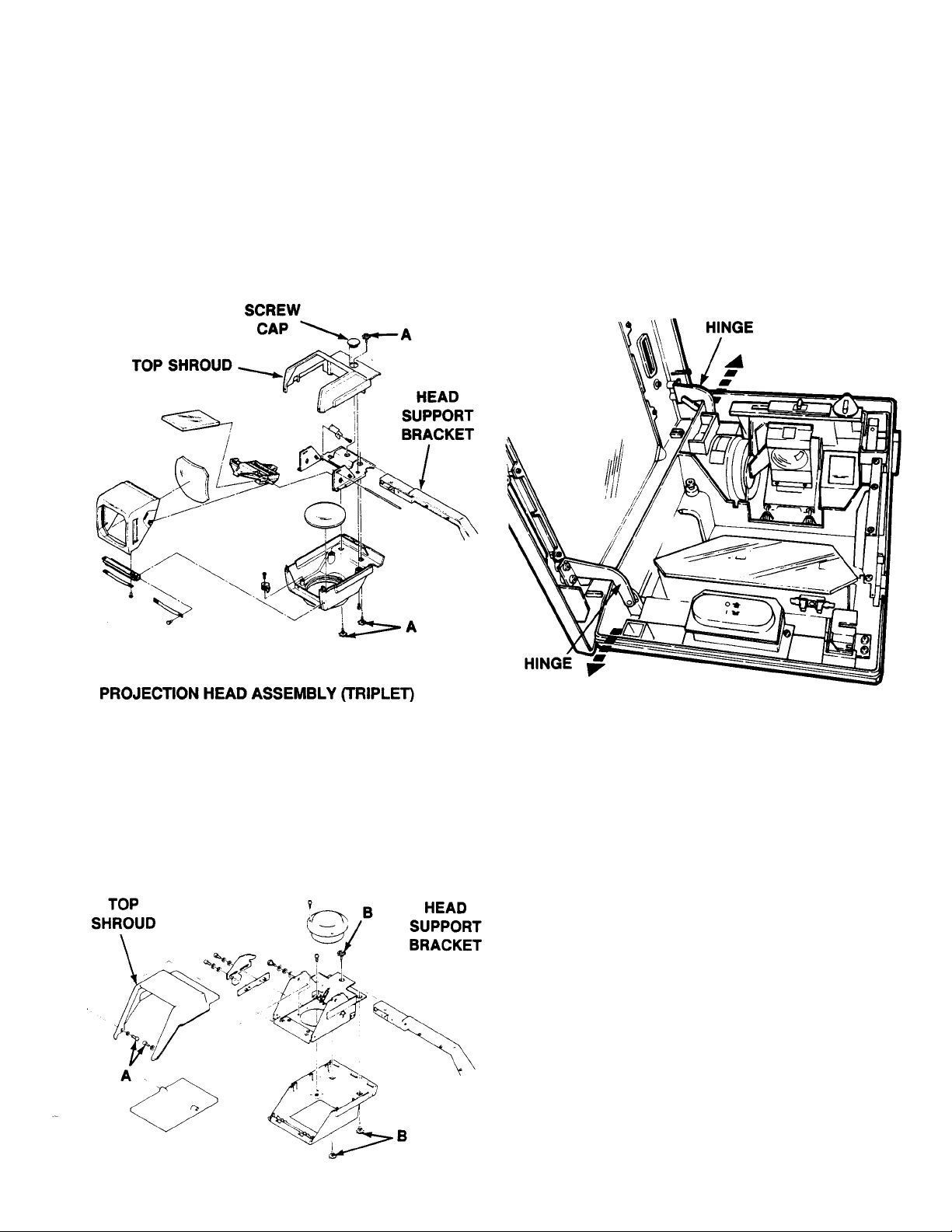
SECTION 6 DISASSEMBLY/RE-ASSEMBLY
PROJECTION HEAD ASSEMBLY (DOUBLET)
1. To disassemble Head Assembly from Head
Support Bracket:
A. Remove Screw Cap from Top Shroud.
B. Remove the three screws (“A”).
C. Slide the Head Assembly off Support
Bracket.
TOP COVER ASSEMBLY
1. Raise the Top Cover Assembly by pulling the
Release Lever and lifting up.
2. Using both hands, pull either one of the two
hinges outward until the hinge pin is out of
the hole. Slide the complete TOP COVER
ASSEMBLY in the opposite direction to
release the second hinge and lift up and out.
2. To disassemble Head Assembly from Head
Support Bracket:
A. Remove the two screws (“A”).
B. Lift the Top Shroud off assembly.
C. Remove the three screws (“B”).
D. Slide the Head Assembly off Support
Bracket.
FRESNEL LENS
1. Remove Top Cover Assembly. (See Figure
above)
2. Loosen the four (4) screws holding the four
(4) corner clips and lens. DO NOT REMOVE
SCREWS. Turn clips to side and remove
lens.
NOTE
When replacing the Fresnel Lens, make
certain the bow in the lens is in the
convex (upward) position when
projector is upright.
See Section 4, page 4-4, for proper alignment
of Fresnel Lens.
9/92
6-1

MODEL 2100 OVERHEAD PROJECTOR
STAGE GLASS
1. Remove Top Cover Assembly.(See page 6-
1)
2. Remove the Fresnel Lens. (See page 6-1)
3. Remove the six (6) tamper proof screws
using a T15 Torx Driver. (3M Part Number
26-1005-8317-3)
4. Remove the MASK (black frame) and Stage
Glass.
5. To reassemble, make certain the beveled
edges on the Stage Glass are facing down
and the 3M logo is in the lower left front
corner. (2140/2150 only, 2130 does not
have logo)
NOTE
This drawing of Stage is up side down.
FOCUSING ASSEMBLY
1 Remove knob.
2. Before disassembling, turn Adjusting Screw
clockwise to loosen assembly.
3. Remove the four “A” screws and cover. (All
internal parts are now exposed.)
4. Before re-assembling, turn adjusting screw
counterclockwise. (This procedure makes
re-assembly easier.)
5. After re-assembly is completed, readjust the
focus tension.
6. Reassemble MASK and Fresnel Lens in
reverse order as noted above.
6-2
9/92

MODEL 2100 OVERHEAD PROJECTOR
How to remove and install the condenser lens (when equipped)
Caution! Wear safety glasses when removing lens.
.020 Feeler Gage
.020 to .030 Gap after installation
Tab
Illustration A Illustration B
1. Insert a Pin Punch or Drill Rod into the hole in the Tab (see illustration A)
2. Release the lens by bending the Tab.
3. Install the new lens and bend the Tab back into place.
Caution! Do not overtighten the tab. The lens must have enough clearance
for expansion. There should be a .20 to .30 gap between the lens and
lens bracket (Illustration B).
Caution! Be careful not to scratch or chip the lens while installing.
9/92
6-3
 Loading...