

Page 1

3Com WX3000 Series Unified Switches
Switching Engine
Operation Manual
Manual Version: 6W100
www.3com.com
3Com Corporation
350 Campus Drive, Marlborough,
MA, USA 01752 3064
Page 2

Copyright © 2009, 3Com Corporation. All rights reserved. No part of this documentation may be reproduced in
any form or by any means or used to make any derivative work (such as translation, transformation, or
adaptation) without written permission from 3Com Corporation.
3Com Corporation reserves the right to revise this documentation and to make changes in co ntent from time to
time without obligation on the part of 3Com Corporation to provide notification of such revision or change.
3Com Corporation provides this documentation without warranty, term, or condition of any kind, either implied
or expressed, including, but not limited to, the implied warranties, terms or conditions of merchantability,
satisfactory quality, and fitness for a particular purpose. 3Com may make improvements or changes in the
product(s) and/or the program(s) described in this documentation at any time.
If there is any software on removable media described in this documentation, it is furnished under a license
agreement included with the product as a separate document, in the hard copy documentation, or on the
removable media in a directory file named LICENSE.TXT or !LICENSE.TXT. If you are unable to locate a copy,
please contact 3Com and a copy will be provided to you.
UNITED STATES GOVERNMENT LEGEND
If you are a United States government agency, then this documentation and the software described herei n are
provided to you subject to the following:
All technical data and computer software are commercial in nature and developed solely at private expense.
Software is delivered as “Commercial Computer Software” as defined in DFARS 252.227 -7014 (June 1995) o r
as a “commercial item” as defined in FAR 2.101(a) and as such is provided with only such rig hts as are
provided in 3Com’s standard commercial license for the Software. Technical data is provided with limited rights
only as provided in DFAR 252.227-7015 (Nov 1995) or FAR 52.227-14 (June 1987), whichever is applicable.
You agree not to remove or deface any portion of any legend provided on any licensed program or
documentation contained in, or delivered to you in conjunction with, this User Guide.
Unless otherwise indicated, 3Com registered trademarks are registered in the United States and may or may
not be registered in other countries.
3Com and the 3Com logo are registered trademarks of 3Com Corporation.
All other company and product names may be trademarks of the respective companies with which they are
associated.
ENVIRONMENTAL STATEMENT
It is the policy of 3Com Corporation to be environmentally-friendly in all operations. To uphold our policy, we
are committed to:
Establishing environmental performance standards that comply with national legislation and regulations.
Conserving energy, materials and natural resources in all operations.
Reducing the waste generated by all operations. Ensuring that all wa ste conforms to recognized environmental
standards. Maximizing the recyclable and reusable content of all products.
Ensuring that all products can be recycled, reused and disp osed of safely.
Ensuring that all products are labelled according to recognized environmental standards.
Improving our environmental record on a continual basis.
End of Life Statement
3Com processes allow for the recovery, reclamation and safe disposal of all end-of-life electronic compon ents.
Regulated Materials Statement
3Com products do not contain any hazardous or ozone-d epleting material.
Environmental Statement about the Documentation
The documentation for this product is printed on paper that comes from sustainabl e, managed forests; it is fully
biodegradable and recyclable, and is completely chlorine-free. The varnish is environmentally-f riendly, and the
inks are vegetable-based with a low heavy-metal content.
Page 3

About This Manual
Organization
3Com WX3000 Series Unified Switches consists of three models: the WX3024 , the WX3010 and the
WX3008. 3Com WX3000 Series Unified Switches Switching Engine Operation Manual is organized as
follows:
Part Contents
1 CLI
Introduces the command hierarchy, command view
and CLI features of the WX3000 Series Unified
Switches Switching Engine.
2 Login
3 Configuration File Management
4 VLAN Introduces VLAN-/Voice VLAN-related configuration.
5 Auto Detect Introduces auto detect and the related configuration.
6 Voice VLAN Introduces voice VLAN and the related configuration.
7 GVRP Introduces GVRP and the related configuration.
8 Basic Port Configuration Introduces basic port configuration.
9 Link Aggregation
10 Port Isolation Introduces port isolation and the related configuration.
11 Port Security-Port Binding
12 DLDP Introduces DLDP and the related configuration.
13 MAC Address Table Management
Introduces the ways to log into an WX3000 Series
Unified Switches Switching Engine.
Introduces configuration file and the related
configuration.
Introduces link aggregation and the related
configuration.
Introduces port security, port binding, and the related
configuration.
Introduces MAC address forwarding table
management.
14 MSTP Introduces STP and the related configuration.
15 802.1x and System Guard Introduces 802.1x and the related configuration.
16 AAA
17 MAC Address Authentication
18 IP Address and Performance
19 DHCP
20 ACL Introduces ACL and the related configuration.
21 QoS-QoS Profile Introduces QoS and the related configuration.
22 Mirroring Introduces mirroring and the related configuration.
23 ARP Introduces ARP and the related configuration.
Introduces AAA, RADIUS, HWTACACS, EAD, and the
related configurations.
Introduces centralized MAC address authentication
and the related configuration.
Introduces IP address and IP performance related
configuration.
Introduces DHCP-Snooping, DHCP Client and the
related configuration.
Page 4

Part Contents
24 SNMP-RMON
25 Multicast
26 NTP Introduces NTP and the related configuration.
27 SSH Introduces SSH2.0 and the related configuration.
28 File System Management
29 FTP-SFTP-TFTP
30 Information Center Introduces information center configuration.
31 System Maintenance and Debugging Introduces daily system maintenance and debugging.
32 VLAN-VPN Introduces VLAN VPN and the related configuration.
33 HWPing Introduces HWPing and the related configuration.
34 DNS Introduces DNS and the related configuration.
35 Smart Link-Monitor Link
Introduces the configuration for network management
through SNMP and RMON
Introduces IGMP snooping and the related
configuration.
Introduces basic configuration for file system
management.
Introduces basic configuration for FTP, SFTP and
TFTP, and the applications.
Introduces Smart Link, Monitor Link and the related
configuration.
36 PoE-PoE Profile
37 Routing Protocol
38 UDP Helper Introduces UDP Helper and the related configuration.
39 Appendix Lists the acronyms used in this manual.
Conventions
The manual uses the following conventions:
Command conventions
Convention Description
Boldface
italic
[ ] Items (keywords or arguments) in square brackets [ ] are optional.
{ x | y | ... }
Introduces PoE, PoE profile and the related
configuration.
Introduces the static route, RIP, and IP route policy
configurations.
The keywords of a command line are in Boldface.
Command arguments are in italic.
Alternative items are grouped in braces and separated by vertical bars.
One is selected.
[ x | y | ... ]
{ x | y | ... } *
[ x | y | ... ] *
Optional alternative items are grouped in square brackets and
separated by vertical bars. One or none is selected.
Alternative items are grouped in braces and separated by vertical bars.
A minimum of one or a maximum of all can be selected.
Optional alternative items are grouped in square brackets and
separated by vertical bars. Many or none can be selected.
Page 5
Convention Description
&<1-n>
# A line starting with the # sign is comments.
The argument(s) before the ampersand (&) sign can be entered 1 to n
times.
GUI conventions
Convention Description
Boldface
>
Window names, button names, field names, and menu items are in
Boldface. For example, the New User window appears; click OK.
Multi-level menus are separated by angle brackets. For example, File >
Create > Folder.
Symbols
Convention Description
Means reader be extremely careful. Improper operation may cause
bodily injury.
Related Documentation
In addition to this manual, each 3Com WX3000 Series Unified Switches Switching Engine
documentation set includes the following:
Manual Description
3Com WX3000 Series Unified Switches
Installation Manual
3Com WX3000 Series Unified Switches
Switching Engine Command Manual
3Com WX3000 Series Unified Switches User
Manual
Means reader be careful. Improper operation may cause data loss or
damage to equipment.
Means a complementary description.
It introduces the installation process, startup,
hardware and software maintenance of WX3000
Series unified switches.
Elaborates on the operation commands for
WX3000 series unified switches switching
engines. It covers the operation commands for
CLI, login, VLAN, GVRP, basic port configurations,
MAC address table management, MSTP, 802.1x,
AAA, ACL, QoS, SNMP, RMON, NTP, and SSH.
Provides a guide to the operation of WX3000
series unified switches access controller engines.
It covers configurations of CLI, VLAN, system
maintenance and debugging, WLAN, IPv4, IPv6,
port basic configurations, multicast protocols,
802.1x, AAA, SSH, ACL, QoS, description of the
acronyms used throughout the manual, and a
command index.
Page 6

Manual Description
3Com WX3000 Series Unified Switches
Web-Based Configuration Manual
Obtaining Documentation
You can access the most up-to-date 3Com product documentation on the Wo rld Wide Web at this URL:
http://www.3com.com.
Introduces the Web-based functions of the access
control engine of WX3000 series unified switches
access controller engines.
Page 7

Table of Contents
1 CLI Configuration ······································································································································1-1
Introduction to the CLI·····························································································································1-1
Command Hierarchy·······························································································································1-1
Switching User Levels·····················································································································1-2
Setting the Level of a Command in a Specific View········································································1-3
CLI Views················································································································································1-4
CLI Features ···········································································································································1-7
Online Help······································································································································1-7
Terminal Display······························································································································1-8
Command History····························································································································1-8
Error Prompts··································································································································1-9
Command Edit·································································································································1-9
i
Page 8

1 CLI Configuration
The sample output information in this manual was created on the WX3024. The output information on
your device may vary.
Introduction to the CLI
A command line interfa ce (CLI) is a user interface to interact with a device. Through the CLI on a device,
a user can enter commands to configure the device and check output information to verify the
configuration. Each device provides an easy-to-use CLI and a set of configuration commands for the
convenience of the user to configure and manage.
The CLI on the devices provide the following features, and so has good manageability and operability.
z Hierarchical command protection: After users of different levels log in, they can only use
commands at their own, or lower, levels. This prevents users from using unauthorized commands
to configure devices.
z Online help: Users can gain online help at any time by entering a question mark (?).
z Debugging: Abundant and detailed debugging information is provided to help users diagnose and
locate network problems.
z Command history function: This enables users to check the commands that they have lately
executed and re-execute the commands.
z Partial matching of commands: The system will use partially matching method to search for
commands. This allows users to execute a command by entering partially-spelled command
keywords as long as the keywords entered can be uniquely identified by the system.
Command Hierarchy
The device uses hierarchical command protection for command lines, so as to inhibit users at lower
levels from using higher-level commands to configure the device.
Based on user privilege, commands are classified into four levels:
z Visit level (level 0): Commands at this level are mainly used to diagnose network, and they cannot
be saved in configuration file. For example, ping, tracert and telnet are level 0 commands.
z Monitor level (level 1): Commands at this level are mainly used to maintain the system and
diagnose service faults, and they cannot be saved in configuration file. Such commands include
debugging and terminal.
z System level (level 2): Commands at this level are mainly used to configure services. Commands
concerning routing and network layers are at this level. These commands can be used to provide
network services directly.
1-1
Page 9

z Manage level (level 3): Commands at this level are associated with the basic operation modules
and support modules of the system. These commands provide support for services. Commands
concerning file system, FTP/TFTP/XModem downloading, user management, and level setting are
at this level.
Users logged into the device fall into four user levels, which correspond to the four command levels
respectively. Users at a specific level can only use the commands at the same level or lower levels.
By default, the Console user (a user who logs into the device through the Console port) is a level-3 user ,
and Telnet u s ers are level-0 users.
Switching User Levels
After logging into the device, users can change their current user levels throu gh a command. Note that:
z If a switching password is set for a specific user level by the super password command, all users
must enter the password correctly when they switch from lower user levels to this level (if a wrong
password is entered, they will remain at their original levels).
z If no switching password is set for a specific user level, the Console user can dire ctly swit ch to the
level, while the Telnet users at lower levels will fail to switch to the level (they will remain at their
original levels) and the information like the following will be displayed: % Password is not set.
Setting a user level switching password
Follow these steps to set a password for use level switching:
To do… Use the command… Remarks
Enter system view
Set the super password
for user level switching
system-view
super password [ level level ]
{ cipher | simple } password
Switching to a specific user level
Follow these steps to switch to a specific user level:
To do… Use the command… Remarks
Switch to a specified user level super [ level ]
—
Required
By default, the super password is
not set.
Required
Execute this command in user view.
z If no user level is specified in the super password command or the super command, level 3 is
used by default.
z For security purpose, the password entered is not displayed when you switch to another user level.
You will remain at the original user level if you have tried three times but failed to enter the correct
password.
1-2
Page 10
Configuration example
After a general user telnets to the device, his/her user level is 0. Now, the network administrator wants
to allow general users to switch to level 3, so that they are able to configure the device.
# A level 3 user sets a switching password for user level 3.
<device> system-view
[device] super password level 3 simple 123
# A general user telnets to the device, and then uses the set password to switch to user level 3.
<device> super 3
Password:
User privilege level is 3, and only those commands can be used
whose level is equal or less than this.
Privilege note: 0-VISIT, 1-MONITOR, 2-SYSTEM, 3-MANAGE
# Af ter configuring the device, the general user switches back to user level 0.
<device> super 0
User privilege level is 0, and only those commands can be used
whose level is equal or less than this.
Privilege note: 0-VISIT, 1-MONITOR, 2-SYSTEM, 3-MANAGE
Setting the Level of a Command in a Specific View
Setting the level of a command in a specific view
Commands fall into four levels: visit (level 0), monitor (level 1), system (level 2), and manage (level 3).
By using the following command, the administrator can change the level of a command in a specific
view as required.
Follow these steps to set the level of a command output description in a specific view:
To do… Use the command… Remarks
Enter system view
Configure the level of a
command in a specific view
z It is recommended not to change the level of a command arbitrarily, for it may cause inconvenience
to maintenance and operation.
z When you change the level of a command with multiple keywords, you should input the keywords
one by one in the order they appear in the command syntax. Otherwise, your configuration wil l not
take effect.
system-view
command-privilege level
level view view command
—
Required
Configuration example
The network administrator (a level 3 user) wants to change some TFTP commands (such as tftp get )
from level 3 to level 0, so that general Telnet users (level 0 users) are able to download files through
TFTP.
1-3
Page 11

# Change the tftp get command in user view (shell) from level 3 to level 0. (Originally , only level 3 user s
can change the level of a command.)
<device> system-view
[device] command-privilege level 0 view shell tftp
[device] command-privilege level 0 view shell tftp 192.168.0.1
[device] command-privilege level 0 view shell tftp 192.168.0.1 get
[device] command-privilege level 0 view shell tftp 192.168.0.1 get bootrom.btm
After the above configuration, general Telnet users can use the tftp get command to download file
bootrom.btm and other files from TFTP server 192.168.0.1 and other TFTP servers.
CLI Views
CLI views are designed for different configuration tasks. They are both correlated and distinguishing.
For example, once a user logs into a device successfully , the user enters user view, where the user can
perform some simple operations such as checking the operation st atus an d stati stics information of the
device. After executing the system-view command, the user enters system view, where the user can
go to other views by entering corresponding commands.
Table 1-1 lists the CLI views provided by the device, operations that can be performed in different CLI
views and the commands used to enter specific CLI views.
Table 1-1 CLI views
View
Available
operation
Display
operation
User view
status and
statistical
information of
the device
System
view
Configure
system
parameters
Prompt example Enter method Quit method
Execute the
quit
command to
log out of the
<device>
Enter user view once logging
into the device.
device.
Execute the
quit or return
command to
return to user
[device]
Execute the system-view
command in user view.
view.
1-4
Page 12

View
Ethernet
port view
VLAN view
VLAN
interface
view
Loopback
interface
view
NULL
interface
view
Local user
view
Available
operation
Configure
Ethernet port
parameters
Configure
VLAN
parameters
Configure
VLAN interface
parameters
Configure
loopback
interface
parameters
Configure
NULL interface
parameters
Configure local
user
parameters
Prompt example Enter method Quit method
1000 Mbps
Ethernet port view:
[device-GigabitEth
ernet1/0/1]
10 Gigabit
Ethernet port view:
[device-TenGigabit
Ethernet1/1/1]
[device-vlan1]
[device-Vlan-interf
ace1]
[device-LoopBack
0]
Execute the interface
gigabitethernet command in
system view.
Execute the interface
tengigabitethernet
command in system view.
Execute the vlan command
in system view.
Execute the interface
Vlan-interface command in
system view.
Execute the interface
loopback command in
system view.
Execute the
quit
command to
return to
[device-NULL0]
Execute the interface null
command in system view.
system view.
Execute the
return
[device-luser-user
1]
Execute the local-user
command in system view.
command to
return to user
view.
User
interface
view
FTP client
view
SFTP
client view
MST
region
view
Cluster
view
Public key
view
Configure user
interface
parameters
Configure FTP
client
parameters
Configure
SFTP client
parameters
Configure MST
region
parameters
Configure
cluster
parameters
Configure the
RSA public key
for SSH users
Configure the
RSA or DSA
public key for
SSH users
[device-ui-aux0]
[ftp]
sftp-client>
[device-mst-region
]
[device-cluster]
[device-rsa-publickey]
[device-peer-public
-key]
Execute the user-interface
aux command in system
view.
Execute the ftp command in
user view.
Execute the sftp command
in system view.
Execute the stp
region-configuration
command in system view.
Execute the cluster
command in system view.
Execute the rsa
peer-public-key command
in system view.
Execute the public-key peer
command in system view.
Execute the
peer-publickey end
command to
return to
system view.
1-5
Page 13

View
Public key
editing
view
Basic ACL
view
Advanced
ACL view
Layer 2
ACL view
Available
operation
Edit the RSA
public key for
SSH users
Edit the RSA or
DSA public key
for SSH users
Define rules for
a basic ACL
(with ID ranging
from 2000 to
2999)
Define rules for
an advanced
ACL (with ID
ranging from
3000 to 3999)
Define rules for
an layer 2 ACL
(with ID ranging
from 4000 to
4999)
Prompt example Enter method Quit method
[device-rsa-key-co
de]
[device-peer-key-c
ode]
[device-acl-basic-2
000]
[device-acl-adv-30
00]
[device-acl-ethern
etframe-4000]
Execute the
public-key-code begin
command in public key view.
Execute the acl number
command in system view.
Execute the acl number
command in system view.
Execute the acl number
command in system view.
Execute the
public-key-c
ode end
command to
return to
public key
view.
QoS profile
view
RADIUS
scheme
view
ISP
domain
view
HWPing
view
HWTACA
CS view
PoE profile
view
Smart-link
group view
Define QoS
profile
Configure
RADIUS
scheme
parameters
Configure ISP
domain
parameters
Configure
HWPing
parameters
Configure
HWTACACS
parameters
Configure PoE
profile
parameters
Configure
smart-link
group
parameters
[device-qos-profile
-a123]
[device-radius-1]
[device-isp-aaa123
.net]
[device-hwping-a1
23-a123]
[device-hwtacacsa123]
[device-poe-profile
-a123]
[device-smlk-group
1]
Execute the qos-profile
command in system view.
Execute the radius scheme
command in system view.
Execute the domain
command in system view.
Execute the hwping
command in system view.
Execute the hwtacacs
scheme command in system
view.
Execute the poe-profile
command in system view.
Execute the smart-link
group command in system
view.
Execute the
quit
command to
return to
system view.
Execute the
return
command to
return to user
view.
Monitor-lin
k group
view
Port-group
view
Configure
monitor-link
group
parameters
Configure
port-group
parameters
[device-mtlk-group
1]
[device-port-group1]
1-6
Execute the monitor-link
group command in system
view.
Execute the port-group
command in system view.
Page 14

View
Available
operation
Prompt example Enter method Quit method
Execute the vlan-vpn vid
command in Ethernet port
QinQ view
Configure QinQ
parameters
[device-GigabitEth
ernet1/0/1-vid-20]
view.
The vlan-vpn enable
command should be first
executed.
The shortcut key combination Ctrl+Z is equivalent to the return command.
Execute the
quit
command to
return to
Ethernet port
view.
Execute the
return
command to
return to user
view.
CLI Features
Online Help
When configuring the device, you can use the online help to get related help information. The CLI
provides two types of online help: complete and partial.
Complete online help
1) Enter a question mark (?) in any view on your terminal to display all the commands available in the
view and their brief descriptions. The following takes user view as an example.
<device> ?
User view commands:
boot Set boot option
cd Change current directory
clock Specify the system clock
cluster Run cluster command
copy Copy from one file to another
debugging Enable system debugging functions
delete Delete a file
dir List files on a file system
display Display current system information
<Other information is omitted>
2) Enter a command, a space, and a question mark (?).
If the question mark “?” is at a keyword position in the command, all available keywords at the position
and their descriptions will be displayed on your terminal.
<device> clock ?
datetime Specify the time and date
summer-time Configure summer time
1-7
Page 15

timezone Configure time zone
If the question mark (?) is at an argument position in the command, the description of the argument will
be displayed on your terminal.
[device] interface vlan-interface ?
<1-4094> VLAN interface number
If only <cr> is displayed after you enter a question mark (?), it means no parameter is avail able at the ?
position, and you can enter and execute the command directly.
[device] interface vlan-interface 1 ?
<cr>
Partial online help
1) Enter a character/string, and then a question mark (?) next to it. All the commands beginning with
the character/string will be displayed on your terminal. For example:
<device> p?
ping
pwd
2) Enter a command, a space, a character/string and a question mark (?) next to it. All the keywords
beginning with the character/string (if available) are displayed on your terminal. For example:
<device> display v?
version
vlan
voice
3) Enter the first several characters of a keyword of a command and then press Tab. If there is a
unique keyword beginning with the characters just typed, the unique keyword is displayed in its
complete form. If there are multiple keywords beginning with the characters, you can have them
displayed one by one (in complete form) by pressing Tab repeatedly.
Terminal Display
The CLI provides the screen splitting feature to have display output suspended when the screen is full.
When display output pauses, you can perform the following operations as needed (see
Table 1-2 Display-related operations
Ctrl+C
Any character except the space, Enter, the
forward slash (/), plus sign (+), and minus
sign (-) when the display output pauses
The space key Go to the next page.
Enter
Table 1-2).
Press To
Stop the display output and execution of the
command.
Stop the display output.
Go to the next line.
Command History
The CLI provides the command history function. You can use the display history-command command
to view a specific number of latest executed commands and execute them again in a convenient way.
1-8
Page 16

By default, the CLI can store up to 10 latest executed commands for each user. You can view the
command history by performing the operations listed in
Table 1-3.
Table 1-3 View history commands
Purpose Operation Remarks
Display the latest executed
history commands
Recall the previous history
command
Recall the next history
command
Execute the display
history-command command
Press the up arrow key or
Ctrl+P
Pressing the down arrow key or
Ctrl+N
This command displays the
command history.
This operation recalls the
previous history command (if
available).
This operation recalls the next
history command (if available).
z Because the Windows 9x HyperTerminal explains the up and down arrow keys in a different way,
the two keys are invalid when you access history commands in a Windows 9x HyperTerminal
environment. However, you can use Ctrl+P and Ctrl+N instead to achieve the same purpose.
z When you enter the same command multiple times con secutively, only one history command ent ry
is created by the command line interface.
Error Prompts
If a command passes the syntax check, it will be successfully executed; otherwise, an error message
will be displayed.
Table 1-4 Common error messages
Unrecognized command
Incomplete command The command entered is incomplete.
Too many parameters The parameters entered are too many.
Ambiguous command The parameters entered are ambiguous.
Wrong parameter A parameter entered is wrong.
found at '^' position An error is found at the '^' position.
Table 1-4 lists the co mmon error messages.
Error message Description
The command does not exist.
The keyword does not exist.
The parameter type is wrong.
The parameter value is out of range.
Command Edit
The CLI provides basic command edit functions and supports multi-line editing. The maximum number
of characters a command can contain is 254.
Table 1-5 list s the CLI edit operations.
1-9
Page 17

Table 1-5 Edit operations
Press… To…
Insert the corresponding character at the cursor position and move
A common key
the cursor one character to the right if the command is shorter than
254 characters.
Backspace key
Delete the character on the left of the cursor and move the cursor
one character to the left.
Left arrow key or Ctrl+B Move the cursor one character to the left.
Right arrow key or Ctrl+F Move the cursor one character to the right.
Up arrow key or Ctrl+P
Down arrow key or Ctrl+N
Display history commands.
Use the partial online help. That is, when you input an incomplete
keyword and press Tab, if the input parameter uniquely identifies a
complete keyword, the system substitutes the complete keyword for
Tab
the input parameter; if more than one keywords match the input
parameter, you can display them one by one (in complete form) by
pressing Tab repeatedly; if no keyword matches the input
parameter, the system displays your original input on a new line
without any change.
1-10
Page 18

Table of Contents
1 Logging In to the Switching Engine ········································································································1-1
Logging In to the Switching Engine·········································································································1-1
Introduction to the User Interface············································································································1-1
Supported User Interfaces ··············································································································1-1
User Interface Index························································································································1-2
Common User Interface Configuration····························································································1-2
2 Logging In Through OAP··························································································································2-1
OAP Overview·········································································································································2-1
Logging In to the Switching Engine Through OAP ·················································································2-1
Configuring the Management IP Address of the OAP Software System················································2-1
Conf i g u ri n g t h e M a n a g ement I P A ddres s o f th e O A P S o f t w a r e S y s t e m o n t h e S w itchi n g E n g in e·······2-2
Configuring the Management IP Address of the OAP Software System of the Access Control
Engine·············································································································································
Resetting the OAP Software System······································································································2-3
3 Logging In Through Telnet·······················································································································3-1
Introduction ·············································································································································3-1
Common Configuration····················································································································3-1
Telnet Configurations for Different Authentication Modes·······························································3-2
Telnet Configuration with Authentication Mode Being None ··································································3-3
Configuration Procedure··················································································································3-3
Configuration Example····················································································································3-4
Telnet Configuration with Authentication Mode Being Password···························································3-5
Configuration Procedure··················································································································3-5
Configuration Example····················································································································3-6
Telnet Configuration with Authentication Mode Being Scheme······························································3-7
Configuration Procedure··················································································································3-7
Configuration Example··················································································································3-10
Telnetting to the Switching Engine········································································································3-11
Telnetting to the Switching Engine from a Terminal······································································3-11
Telnetting to the Switching Engine from the Access Control Engine············································3-13
2-2
4 Logging In from the Web-Based Network Management System··························································4-1
Introduction ·············································································································································4-1
Setting Up a Web Configuration Environment························································································4-2
Configuring the Login Banner·················································································································4-3
Configuration Procedure··················································································································4-3
Configuration Example····················································································································4-4
Enabling/Disabling the WEB Server ·······································································································4-5
5 Logging In from NMS ································································································································5-1
Introduction ·············································································································································5-1
Connection Establishment Using NMS···································································································5-1
6 Configuring Source IP Address for Telnet Service Packets·································································6-1
Overview·················································································································································6-1
i
Page 19

Configuring Source IP Address for Telnet Service Packets ···································································6-1
Displaying Source IP Address Configuration··························································································6-2
7 User Control···············································································································································7-1
Introduction ·············································································································································7-1
Controlling Telnet Users ·························································································································7-1
Prerequisites····································································································································7-1
Controlling Telnet Users by Source IP Addresses··········································································7-1
Controlling Telnet Users by Source and Destination IP Addresses················································7-2
Controlling Telnet Users by Source MAC Addresses ·····································································7-3
Configuration Example····················································································································7-3
Controlling Network Management Users by Source IP Addresses························································7-4
Prerequisites····································································································································7-4
Controlling Network Management Users by Source IP Addresses·················································7-4
Configuration Example····················································································································7-5
Controlling Web Users by Source IP Address························································································7-5
Prerequisites····································································································································7-6
Controlling Web Users by Source IP Addresses·············································································7-6
Disconnecting a Web User by Force·······························································································7-6
Configuration Example····················································································································7-6
ii
Page 20
1 Logging In to the Switching Engine
The sample output information in this manual was created on the WX3024. The output information on
your device may vary.
Logging In to the Switching Engine
You can log in to the switching engine of the device in one of the following ways:
z Logging in through OAP
z Logging in locally or remotely through an Ethernet port by means of Telnet or SSH
z Logging in to the Web-based network management system
z Logging in through NMS (network management station)
Introduction to the User Interface
Supported User Interfaces
The auxiliary (AUX) port and the console port of the device are the same port (referred to as console
port in the following part). You will be in the AUX user interface if you log in through this port.
The device supports two types of user interfaces: AUX and VTY.
z AUX user interface: A view when you log in through the console port.
z Virtual type terminal (VTY) user interface: A view when you log in through VTY. VTY port is a
logical terminal line used when you access the device by means of Telnet or SSH.
Table 1-1 Description on user interface
User interface Applicable user Port used Description
AUX
VTY
Users logging in through
the console port
Telnet users and SSH
users
Console port
Ethernet port
1-1
Each device can accommodate
one AUX user.
Each device can accommodate
up to five VTY users.
Page 21

User Interface Index
Two kinds of use r interfa ce index exist: absolute user interface index and relative user interface index.
1) The absolute user interface indexes are as follows:
z The absolute AUX user interfaces is numbered 0.
z VTY user interface indexes follow AUX user interface indexes. The first absolute VTY user
interface is numbered 1, the second is 2, and so on.
2) A relative user interface index can be obtained by appending a number to the identifier of a user
interface type. It is generated by user interface type. The relative user interface indexes are as
follows:
z AUX user interfaces is numbered 0.
z VTY user interfaces are numbered VTY0, VTY1, and so on.
Common User Interface Configuration
Follow these steps to configure common user interface:
To do… Use the command… Remarks
Lock the current user
interface
lock
Optional
Execute this command in user view.
A user interface is not locked by
default.
Specify to send messages to
all user interfaces/a specified
user interface
Free a user interface
Enter system view
Set the banner
Set a system name for the
switching engine
Enable copyright information
displaying
Enter user interface view
send { all | number | type
number }
free user-interface [ type ]
number
system-view
header [ incoming | legal |
login | shell ] text
sysname string
copyright-info enable
user-interface [ type ]
first-number [ last-number ]
Optional
Execute this command in user view.
Optional
Execute this command in user view.
—
Optional
By default, no banner is configured.
Optional
By default, the system name is
device.
Optional
By default, copyright displaying is
enabled. That is, the copy right
information is displayed on the
terminal after a user logs in
successfully.
—
1-2
Page 22

To do… Use the command… Remarks
Display the information about
the current user interface/all
display users [ all ]
user interfaces
Display the physical
attributes and configuration
of the current/a specified
user interface
Display the information about
the current web users
display user-interface
[ type number | number ]
display web users
Optional
You can execute the display
command in any view.
1-3
Page 23

2 Logging In Through OAP
OAP Overview
As an open software and hardware system, Open Application Architecture (OAA) provides a set of
complete standard software and hardware interfaces. The third party vendors can develop products
with special functions. These products can be comp atible with each other as long as they conform to the
OAA interface standards. Therefore the functions of single network product can be expanded and the
users can get more benefits.
Open Application Platform (OAP) is a physical platform developed based on OAA. It can be an
independent network device, or a board or pro gram used as an extended part of a device. An OAP runs
an independent operating system. You can load software such as security and voice in the operating
system as needed.
Logging In to the Switching Engine Through OAP
You can log in to the access control engine through the console port on the device and perform the
following configurations on the access control engine. Then, you can log in to the switching engine.
1) Execute the oap connect slot 0 command in user view of the access control engine to log in to the
switching engine.
<device> oap connect slot 0
Connected to OAP!
2) Press Enter to enter user view of the switching engine.
<device_LSW>
z To distinguish between the access control engine and the switching engine, the name of the
switching engine is changed to device_LSW here. In fact, the default name of the switching engine
is device.
z You can press Ctrl+K to return to the command line interface of the access control engine.
Configuring the Management IP Address of the OAP Software System
In the OAA system of the device, the access cont rol engine and the switching engine integ rate together
and function as one device. For the snmp UDP Domain-based network management station (NMS),
however, the access control engine and t he switching engine are independent SNMP agents. Physically ,
two agents are on the same managed object; while logically, they belong to two different systems, and
they manage their own MIB objects on the access control engine and the switching engine separately.
2-1
Page 24

Therefore, when you use the NMS to manage the access control engine and the switching engine on
the same interface, you must first obtain the management IP addresses of the two SNMP agents and
obtain the link relationship between them, and then you can access the two agents. By default, the
management IP address of an OAP mod ule is not con f igured.
Before configuring the management IP address of the OAP software system, you must configure the
same IP address at the engine side where the OAP software system resides; otherwise, the NMS
cannot access the OAP software system by using the configured management IP address.
Follow these steps to configure the management IP address of the OAP software system:
To do… Use the command… Remarks
Enter system view
Configure the management IP
address of an OAP module
system-view
oap management-ip
ip-address slot 0
—
Required
Not configured by default.
Configuring the Management IP Address of the OAP Software System on the Switching Engine
1) Configure the management IP address of the OAP software system on the switching engine side.
<device_LSW> system-view
[device_LSW] interface vlan-interface 1
[device_LSW-Vlan-interface1] ip address 192.168.0.2 24
Press Ctrl+K to return to the command line operating interface of the access control engine.
2) Configure the management IP address of the SNMP agent on the access control engine.
<device> system-view
[device] oap management-ip 192.168.0.2 slot 0
Configuring the Management IP Address of the OAP Software System of the Access Control Engine
1) Configure the management IP address of the OAP software system on the access control engine
side.
<device> system-view
[device] interface Vlan-interface 1
[device-Vlan-interface1] ip address 192.168.0.1 24
2) Log in to the switching engine, and configure the management IP address of the SNMP agent on
the switching engine.
<device> oap connect slot 0
Connected to OAP!
<device_LSW> system-view
[device_LSW] oap management-ip 192.168.0.1 slot 0
2-2
Page 25

Resetting the OAP Software System
If the operating system works abnormally or is under other anomali es, you ca n reset the OAP software
system.
Follow these steps to reset the OA P software system:
To do… Use the command… Remarks
Reset the OAP software
system
The reset operation may cause data loss and service interruption. Therefore, before resetting the OAP
software system, you need to save the data on the operating system to avoid service interruption and
hardware data loss.
oap reboot slot 0
Required
Available in user view
2-3
Page 26

3 Logging In Through Telnet
Introduction
The device supports Telnet. Y ou can manage an d maintain the swit ching engine remotely by Telnetting
to the switching engine.
To log in to the switching engine through Telnet, the corresponding configuration is required on both the
switching engine and the Telnet terminal.
Y ou can also log in to the switching engine through SSH. SSH is a secure shell added to Telnet. Refer to
the SSH Operation for related information.
Table 3-1 Requirements for Telnetting to the switching engine
Item Requirement
Switching engine
Telnet terminal
Common Configuration
Table 3-2 lists the common Telnet configuration.
Table 3-2 Common Telnet configuration
Configuration Description
Configure the command level
available to users logging in to
the VTY user interface
The IP address is configured for the VLAN of the switching engine,
and the route between the switching engine and the Telnet termi nal is
reachable. (Refer to the IP Address and Performance Operation and
Routing Protocol parts for more.)
The authentication mode and other settings are configured. Refer to
Table 3-2 and Table 3-3.
Telnet is running.
The IP address of the VLAN of the switching engine is available.
Optional
By default, commands of level 0 are available
to users logging in to a VTY user interface.
VTY user
interface
configuration
Configure the protocols the user
interface supports
Set the commands to be
executed automatically after a
user log in to the user interface
successfully
3-1
Optional
By default, Telnet and SSH protocol are
supported.
Optional
By default, no command is executed
automatically after a user logs into the VTY
user interface.
Page 27

Configuration Description
Optional
Make terminal services available
By default, terminal services are available in
all user interfaces
Optional
By default, the screen can contain up to 24
lines.
VTY terminal
Set the maximum number of
lines the screen can contain
configuration
Optional
Set history command buffer size
By default, the history command buffer can
contain up to 10 commands.
Set the timeout time of a user
interface
Optional
The default timeout time is 10 minutes.
Telnet Configurations for Different Authentication Modes
Table 3-3 lists Telnet configurations for different authentication modes.
Table 3-3 Telnet configurations for different authentication modes
Authentication
mode
None
Perform common
configuration
Telnet configuration Description
Perform common
Telnet configuration
Optional
Refer to
Table 3-2.
Password
Scheme
Configure the
password
Perform common
configuration
Specify to
perform local
authentication or
remote RADIUS
authentication
Configure user
name and
password
Manage VTY
users
Configure the
password for local
authentication
Perform common
Telnet configuration
AAA configuration
specifies whether to
perform local
authentication or
RADIUS authentication
Configure user names
and passwords for
local/RADIUS users
Set service type for
VTY users
Required
Optional
Refer to
Table 3-2.
Optional
Local authentication is
performed by default.
Refer to the AAA part for more.
Required
z The user name and
password of a local user are
configured on the switching
engine.
z The user name and
password of a remote user
are configured on the
RADIUS server. Refer to
user manual of RADIUS
server for more.
Required
Perform common
configuration
Perform common
Telnet configuration
Optional
Refer to
Table 3-2.
3-2
Page 28

To improve security and prevent attacks to the unused Sockets, TCP 23 and TCP 22, ports for Telnet
and SSH services respectively, will be enabled or disabled after corresponding configurations.
z If the authentication mode is none, TCP 23 will be enabled, and TCP 22 will be disabled.
z If the authentication mode is password, and the corresponding password has been set, TCP 23
will be enabled, and TCP 22 will be disabled.
z If the authentication mode is scheme, there are three scenarios: when the supported protocol is
specified as telnet, TCP 23 will be enabled; when the supported protocol is specified as ssh, TCP
22 will be enabled; when the supported protocol is specified as all, both the TCP 23 and TCP 22
port will be enabled.
Telnet Configuration with Authentication Mode Being None
Configuration Procedure
Follow these steps to perform Telnet configuration with the authentication mode being none:
To do… Use the command… Remarks
Enter system view
Enter one or more VTY user
interface views
Configure not to authenticate
users logging in to VTY user
interfaces
Configure the command level
available to users logging in to
VTY user interface
Configure the protocols to be
supported by the VTY user
interface
Set the commands to be
executed automatically after a
user login to the user interface
successfully
system-view
user-interface vty
first-number
[ last-number ]
authentication-mode
none
user privilege level
level
protocol inbound { all |
ssh | telnet }
auto-execute
command text
—
—
Required
By default, VTY users are authenticated
after logging in.
Optional
By default, commands of level 0 are
available to users logging in to VTY
user interfaces.
Optional
By default, both Telnet protocol and
SSH protocol are supported.
Optional
By default, no command is executed
automatically after a user logs in to the
VTY user interface.
Make terminal services
available
Set the maximum number of
lines the screen can contain
shell
screen-length
screen-length
3-3
Optional
By default, terminal services are
available in all user interfaces.
Optional
By default, the screen can contain up to
24 lines.
You can use the screen-length 0
command to disable the function to
display information in pages.
Page 29
To do… Use the command… Remarks
Optional
Set the history command
buffer size
history-command
max-size value
The default history command buffer
size is 10. That is, a history command
buffer can store up to 10 commands by
default.
Optional
The default timeout time of a user
interface is 10 minutes.
With the timeout time being 10 minutes,
Set the timeout time of the
VTY user interface
idle-timeout minutes
[ seconds ]
the connection to a user interface is
terminated if no operation is performed
in the user interface within 10 minutes.
You can use the idle-timeout 0
command to disable the timeout
function.
Note that if you configure not to authenticate the users, the command level available to users logging in
to the switching engine depends on the user privilege level level command
Configuration Example
Network requirements
As shown in Figure 3-1, assume current user logs in using the oap connect slot 0 command, and the
user level is set to the manage level (level 3). Perform the following configurations for users logging in
through VTY 0 using Telnet.
z Do not authenticate the users.
z Commands of level 2 are available to the users.
z Telnet protocol is supported.
z The screen can contain up to 30 lines.
z The history command buffer can contain up to 20 commands.
z The timeout time of VTY 0 is 6 minutes.
Figure 3-1 Network diagram for Telnet configuration (with the authentication mode being none)
Configuration procedure
# Enter system view.
<device> system-view
# Enter VTY 0 user interface view.
[device] user-interface vty 0
# Configure not to authenticate Telnet users logging in through VTY 0.
[device-ui-vty0] authentication-mode none
3-4
Page 30

# Specify commands of level 2 are available to users logging in through VTY 0.
[device-ui-vty0] user privilege level 2
# Configure Telnet protocol is supported.
[device-ui-vty0] protocol inbound telnet
# Set the maximum number of lines the screen can contain to 30.
[device-ui-vty0] screen-length 30
# Set the maximum number of commands the history command buffer can store to 20.
[device-ui-vty0] history-command max-size 20
# Set the timeout time to 6 minutes.
[device-ui-vty0] idle-timeout 6
Telnet Configuration with Authentication Mode Being Password
Configuration Procedure
Follow these steps to perform Telnet configuration with the authentication mode being pa ssword:
To do… Use the command… Remarks
Enter system view
Enter one or more VTY user
interface views
Configure to authenticate users
logging in to VTY user interfaces
using the local password
Set the local password
Configure the command level
available to users logging in to
the user interface
Configure the protocol to be
supported by the user interface
Set the commands to be
executed automatically after a
user login to the user interface
successfully
system-view
user-interface vty
first-number [ last-number ]
authentication-mode
password
set authentication
password { cipher |
simple } password
user privilege level level
protocol inbound { all |
ssh | telnet }
auto-execute command
text
—
—
Required
Required
Optional
By default, commands of level 0
are available to users logging in to
VTY user interface.
Optional
By default, both Telnet protocol
and SSH protocol are supported.
Optional
By default, no command is
executed automatically after a
user logs into the VTY user
interface.
Make terminal services
available
Set the maximum number of
lines the screen can contain
shell
screen-length
screen-length
3-5
Optional
By default, terminal services are
available in all user interfaces.
Optional
By default, the screen can contain
up to 24 lines.
You can use the screen-length 0
command to disable the function
to display information in pages.
Page 31

To do… Use the command… Remarks
Optional
Set the history command buffer
size
history-command
max-size value
The default history command
buffer size is 10. That is, a history
command buffer can store up to
10 commands by default.
Optional
The default timeout time of a user
interface is 10 minutes.
With the timeout time being 10
Set the timeout time of the user
interface
idle-timeout minutes
[ seconds ]
minutes, the connection to a user
interface is terminated if no
operation is performed in the user
interface within 10 minutes.
You can use the idle-timeout 0
command to disable the timeout
function.
Note that when the authentication mode is password, the command level available to users logging in to
the user interface is determined by the user privilege level level command.
Configuration Example
Network requirements
As shown in Figure 3-2, assume current user logs in using the oap connect slot 0 command, and the
user level is set to the manage level (level 3). Perform the following configurations for users logging in to
VTY 0 using Telnet.
z Authenticate users using the local password.
z Set the local password to 123456 (in plain text).
z Commands of level 2 are available to the users.
z Telnet protocol is supported.
z The screen can contain up to 30 lines.
z The history command buffer can contain up to 20 commands.
z The timeout time of VTY 0 is 6 minutes.
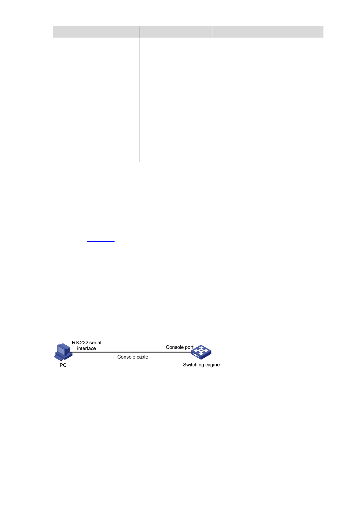
Figure 3-2 Network diagram for Telnet configuration (with the authentication mode being password)
RS-232 serial
interface
PC
Console cable
Console port
Switching engine
Configuration procedure
# Enter system view.
<device> system-view
# Enter VTY 0 user interface view.
[device] user-interface vty 0
# Configure to authenticate users logging in to VTY 0 using the password.
3-6
Page 32

[device-ui-vty0] authentication-mode password
# Set the local password to 123456 (in plain text).
[device-ui-vty0] set authentication password simple 123456
# Specify commands of level 2 are available to users logging in to VTY 0.
[device-ui-vty0] user privilege level 2
# Configure Telnet protocol is supported.
[device-ui-vty0] protocol inbound telnet
# Set the maximum number of lines the screen can contain to 30.
[device-ui-vty0] screen-length 30
# Set the maximum number of commands the history command buffer can store to 20.
[device-ui-vty0] history-command max-size 20
# Set the timeout time to 6 minutes.
[device-ui-vty0] idle-timeout 6
Telnet Configuration with Authentication Mode Being Scheme
Configuration Procedure
Follow these steps to perform Telnet configuration with the authentication mode being scheme:
To do… Use the command… Remarks
Enter system view
Enter the
default ISP
domain view
Configure the
AAA scheme
to be applied
Configure
the
authenticati
on scheme
to the domain
Quit to
system view
system-view
domain domain-name
scheme { local | none |
radius-scheme
radius-scheme-name
[ local ] | hwtacacs-scheme
hwtacacs-scheme-name
[ local ] }
quit
—
Optional
By default, the local AAA scheme is
applied. If you specify to apply the
local AAA scheme, you need to
perform the configuration
concerning local user as well.
If you specify to apply an existing
scheme by providing the
radius-scheme-name argument,
you need to perform the following
configuration as well:
z Perform AAA and RADIUS
configuration on the switching
engine. (Refer to the AAA part
for more.)
z Configure the user name and
password accordingly on the
AAA server. (Refer to the user
manual of the AAA server.)
Create a local user and enter
local user view
Set the authentication
password for the local user
Specify the service type for
VTY users
Quit to system view
local-user user-name
password { simple | cipher }
password
service-type telnet [ level
level ]
quit
3-7
No local user exists by default.
Required
Required
—
Page 33

To do… Use the command… Remarks
Enter one or more VTY user
interface views
Configure to authenticate
users locally or remotely
Configure the command level
available to users logging in
to the user interface
Configure the supported
protocol
Set the commands to be
executed automatically after
a user login to the user
interface successfully
Make terminal services
available
user-interface vty
first-number [ last-number ]
authentication-mode
scheme [ commandauthorization ]
user privilege level level
protocol inbound { all | ssh
| telnet }
auto-execute command
text
shell
—
Required
The specified AAA scheme
determines whether to authenticate
users locally or remotely.
Users are authenticated locally by
default.
Optional
By default, commands of level 0 are
available to users logging in to the
VTY user interfaces.
Optional
Both Telnet protocol and SSH
protocol are supported by default.
Optional
By default, no command is
executed automatically after a user
logs into the VTY user interface.
Optional
Terminal services are available in
all use interfaces by default.
Set the maximum number of
lines the screen can contain
Set history command buffer
size
Set the timeout time for the
user interface
screen-length screen-length
history-command max-size
value
idle-timeout minutes
[ seconds ]
Optional
By default, the screen can contain
up to 24 lines.
You can use the screen-length 0
command to disable the function to
display information in pages.
Optional
The default history command buffer
size is 10. That is, a history
command buffer can store up to 10
commands by default.
Optional
The default timeout time of a user
interface is 10 minutes.
With the timeout time being 10
minutes, the connection to a user
interface is terminated if no
operation is performed in the user
interface within 10 minutes.
You can use the idle-timeout 0
command to disable the timeout
function.
Note that if you configure to authenticate the users in the scheme mode, the command level available to
the users logging in to the switching engine depends on the user privilege level level command and
the service-type { ftp | lan-access | { ssh | telnet | terminal }* [ level level ] } command, as listed in
Table 3-4.
3-8
Page 34

Table 3-4 Determine the command level when users logging in to the switching engine are
authenticated in the scheme mode
Authentication
mode
authenticationmode scheme
[ command-auth
orization ]
Scenario
User type Command
The user privilege level level command is
not executed, and the service-type
command does not specify the available
command level.
The user privilege level level command is
VTY users that
are
AAA/RADIUS
authenticated or
locally
authenticated
not executed, and the service-type
command specifies the available command
level.
The user privilege level level command is
executed, and the service-type command
does not specify the available command
level.
The user privilege level level command is
executed, and the service-type command
specifies the available command level.
The user privilege level level command is
not executed, and the service-type
command does not specify the available
command level.
The user privilege level level command is
VTY users that
are
authenticated in
the RSA mode
of SSH
not executed, and the service-type
command specifies the available command
level.
The user privilege level level command is
executed, and the service-type command
does not specify the available command
level.
The user privilege level level command is
executed, and the service-type command
specifies the available command level.
Command
level
Level 0
Determined
by the
service-type
command
Level 0
Determined
by the
service-type
command
Level 0
Determined
by the user
privilege
level level
command
The user privilege level level command is
not executed, and the service-type
command does not specify the available
Level 0
command level.
VTY users that
are
The user privilege level level command is
not executed, and the service-type
command specifies the available command
level.
Determined
by the
service-type
command
authenticated in
the password
mode of SSH
The user privilege level level command is
executed, and the service-type command
does not specify the available command
Level 0
level.
The user privilege level level command is
executed, and the service-type command
specifies the available command level.
Determined
by the
service-type
command
3-9
Page 35

Refer to AAA Operation and SSH Operation of this manual for information about AAA, RADIUS, and
SSH.
Configuration Example
Network requirements
As shown in Figure 3-3, assume a current user logs in using the oap connect slot 0 command and the
user level is set to the manage level (level 3). Perform the following configurations for users logging in to
VTY 0 using Telnet.
z Configure the local user name as guest.
z Set the authentication password of the local user to 123456 (in plain text).
z Set the service type of VTY users to Telnet and the command level to 2.
z Configure to authenticate users logging in to VTY 0 in scheme mode.
z Only Telnet protocol is supported in VTY 0.
z The screen can contain up to 30 lines.
z The history command buffer can store up to 20 commands.
z The timeout time of VTY 0 is 6 minutes.
Figure 3-3 Network diagram for Telnet configuration (with the authentication mode being sche me)
RS-232 serial
interface
Console cable
PC
Console port
Switching engine
Configuration procedure
# Enter system view.
<device> system-view
# Create a local user named guest and enter local user view.
[device] local-user guest
# Set the authentication password of the local user to 123456 (in plain text).
[device-luser-guest] password simple 123456
# Set the service type to Telnet, Specify commands of level 2 are available to users logging in to VTY 0.
[device-luser-guest] service-type telnet level 2
[device-luser-guest] quit
# Enter VTY 0 user interface view.
[device] user-interface vty 0
# Configure to authenticate users logging in to VTY 0 in the scheme mode.
[device-ui-vty0] authentication-mode scheme
# Configure Telnet protocol is supported.
3-10
Page 36

[device-ui-vty0] protocol inbound telnet
# Set the maximum number of lines the screen can contain to 30.
[device-ui-vty0] screen-length 30
# Set the maximum number of commands the history command buffer can store to 20.
[device-ui-vty0] history-command max-size 20
# Set the timeout time to 6 minutes.
[device-ui-vty0] idle-timeout 6
Telnetting to the Switching Engine
Telnetting to the Switching Engine from a Terminal
1) Assign an IP address to VLAN-interface 1 of the access control engine of the device (VLAN 1 i s the
default VLAN of the access control engine).
z Connect the serial port of your PC/terminal to the console port of the device, as shown in Figure
3-4.
Figure 3-4 Diagram for establishing connection to a console port
z Launch a terminal emulation utility (such as Terminal in Windows 3.X or HyperTerminal in
Windows 95/Windows 98/Windows NT/Windows 2000/Windows XP) on the PC terminal, with the
baud rate set to 9,600 bps, data bits set to 8, parity check set to none, and flow control set to none.
z Power on the device and press Enter as prompted. The prompt (such as <device>) appears, as
shown in the following figure.
Figure 3-5 The terminal window
3-11
Page 37

z Perform the following operations in the terminal window to assign IP address 202.38.160.90/24 to
VLAN–interface 1 of the access control engine.
<device> system-view
[device] interface Vlan-interface 1
[device-Vlan-interface1] ip address 202.38.160.90 255.255.255.0
z Log in to the switching engine of the device using the oap connect slot 0 command.
<device>oap connect slot 0
Connected to OAP!
z Configure the IP address of VLAN-interface 1 of the switching engine of the device as
202.38.160.92/24.
<device_LSW> system-view
[device_LSW] interface Vlan-interface 1
[device_LSW-Vlan-interface1] ip address 202.38.160.92 255.255.255.0
To distinguish between the access control engine and the switching engine, the name of the switching
engine is changed to device_LSW here. In fact, the default name of the switching engine is device.
2) Perform Telnet-related configuration on the switching engine. For details, refer to
Configuration with Authentication Mode Being None
Mode Being Password
, and Telnet Configuration with Authentication Mode Being Scheme.
3) Connect your PC/terminal and the switching engine to an Ethernet, as shown in
, Telnet Configuration with Authentication
Figure 3-6. Make
sure the port through which the switching engine is connected to the Ethernet belongs to VLAN 1
and the route between your PC and VLAN-interface 1 is reachable.
Figure 3-6 Network diagram for Telnet connection establishment
Telnet
4) Launch Telnet on your PC, with the IP address of VLAN–interface 1 of the switching engine as the
parameter, as shown in
Figure 3-7.
3-12
Page 38

Figure 3-7 Launch Telnet
5) If the password authentication mode is specified, enter the password when the Telnet window
displays “Login authentication” and prompts for login password. The CLI prompt (such as
<System_LSW>) appears if the password is correct. If all VTY user interfaces of the switching
engine are in use, you will fail to establish the connection and see the message “All user interfaces
are used, please try later!” The switching engine of the device can accommodate up to five Telnet
connections at same time.
6) After successfully Telnetting to the switching engine, you can configure the switching engine or
display the information about the switching engine by executing corresponding commands. You
can also type ? at any time for help. Refer to the relevant parts in this manual for the information
about the commands.
z A Telnet connection is terminated if you delete or modify the IP address of the VLAN interface in
the Telnet session.
z By default, commands of level 0 are available to Telnet users authenticated by password. For the
command hierarchy and command views, refer to CLI Operation in this manual.
Telnetting to the Switching Engine from the Access Control Engine
You can T elnet to the switching engine from the access control engine. In this case, the access control
engine operates as the client, and the switching engine operates as the server. If the interconnected
Ethernet ports of the two engines are in the same LA N segment, make sure the IP addresses of the two
management VLAN interfaces to which the two Ethernet ports belong are of the same network segment,
or the route between the two VLAN interfaces is available.
As shown in
Telnet to the switching engine (labeled as Telnet server) by executing the telnet command and then
configure it.
Figure 3-8, after Telnetting to the access control engine (labeled as Telnet client), you can
Figure 3-8 Network diagram for Telnetting to the switching engine from the access control engine
3-13
Page 39

1) Perform Telnet-related configuration on the switching engine operating as the Telnet server. For
details, refer to
with Authentication Mode Being Password
Being Scheme
Telnet Configuration with Authentication Mode Being None, Telnet Configuration
, and Telnet Configuration with Authentication Mode
.
2) Telnet to the access control engine as the Telnet client.
3) Execute the following command on the access cont rol engine operating as the Telnet client:
<device> telnet xxxx
Note that xxxx is the IP address or the host name of the access control engine operating as the Telnet
server. You can use the ip host to assign a host name to the access control engine.
4) After successful login, the CLI prompt (such as <device>) appears. If all the VTY user interfaces of
the switching engine are in use, you will fail to establish the connection and receive the message
that says “All user interfaces are used, please try later!”.
5) After successfully Telnetting to the switching engine, you can configure the switching engine or
display the information about the switching engine by executing corresponding commands. You
can also type ? at any time for help. Refer to the subsequent chapters for the information about the
commands.
3-14
Page 40

4 Logging In from the Web-Based Network
Management System
When logging in from the Web-based network management system, go to these sections for
information you are interested in:
z Introduction
z Setting Up a Web Configuration Environment
z Configuring the Login Banner
z Enabling/Disabling the WEB Server
Introduction
The device has a Web server built in. It enables you to log in to switching engine from a Web browser
and then manage and maintain the device intuitively by interacting with the built-in Web server.
To log in to the built-in Web-based network management system of the switching engine, you need to
perform the related configuration on both the switching engine and the PC operating as the network
management terminal.
Table 4-1 Requirements for logging in to the switching engine from the Web-based network
management system
Item Requirement
The VLAN interface of the switching engine is assigned an IP
address, and the route between the switching engine and the Web
network management terminal is reachable. (Refer to IP Address and
Switching engine
PC operating as the
network management
terminal
Performance Operation and Routing Protocol parts for related
information.)
The user name and password for logging in to the Web-based
network management system are configured.
IE is available.
The IP address of the VLAN interface of the switching engine, the
user name, and the password are available.
4-1
Page 41

Setting Up a Web Configuration Environment
Your WX series access controller products were delivered with a factory default configuration. This
configuration allows you to log into the built-in Web-based management sy stem of the access controller
product from a Web browser on a PC by inputting http://192.168.0.101 in the address bar of the
browser. The default login username and password are both admin. After selecting your desired
language, you can log in to the Web interface to make configuration. If you save your configuration, the
device will boot with the configuration you made rather than the default at the next boot.
Log in to the switching engine with the oap connect slot 0 command and then perform the following
operations.
1) Assign an IP address to VLAN-interface 1 of the switching engine (VLAN 1 is the default VLAN of
the switching engine), and create a user account for the login user.
# Assign an IP address to the switching engine.
<device> system-view
[device] interface Vlan-interface 1
[device-Vlan-interface1] ip address 192.168.0.101 24
[device-Vlan-interface1] quit
# Create a Web user account, setting both the user name and the password to admin and the user level
to 3 (manage level).
[device] local-user admin
[device-luser-admin] service-type telnet level 3
[device-luser-admin] password simple admin
device-luser-admin] quit
[
2) Configure the management IP address for the switching engine of the device (Optional).
# After configuring the IP address, you can go to the Web interface of the switching engine from the
Web interface of the access controller engine by clicking the Wireless Engine button on the left upper
part of the page, as shown in
Figure 4-1. 192.168.0.100 is the management IP address of the switching
engine, and slot 0 is the slot number of the switching engine.
[device] oap management-ip 192.168.0.100 slot 0
4-2
Page 42

Figure 4-1 Web interface of the access controller engine
3) Set up a Web configuration environment, as shown in
Figure 4-2 Set up a Web configuration environment
Figure 4-2.
4) Log in to the switching engine through IE. Launch IE on the Web-based network management
terminal (your PC) and enter http://192.168.0.101 in the address bar. (Make sure a route is
available between the Web-based network management terminal and the switching engine.)
5) When the login authentication interface (as shown in
the password configured in step 2 and click Login to bring up the main page of the Web-based
network management system.
Figure 4-3 The login page of the Web-based network management system
Figure 4-3) appears, enter the user name and
Configuring the Login Banner
Configuration Procedure
If a login banner is configured with the header command, when a user logs in through We b, the banner
page is displayed before the user login authentication page. The contents of the banner page are the
login banner information configured with the header command. Then, by clicking <Continue> on the
banner page, the user can enter the user login authentication page, and enter the main page of the
Web-based network management system after passing the authentication. If no login banner is
4-3
Page 43

configured by the header command, a user logging in through Web directly enters the user login
authentication page.
Follow these steps to configure the login banner:
To do… Use the command… Remarks
Enter system view
Configure the banner to be
displayed when a user logs in
through Web
Configuration Example
Network requirements
As shown in Figure 4-4,
z A user logs in to the switching engine through Web.
z The banner page is desired when a user logs in to the switching engine.
Figure 4-4 Network diagram for login banner configuration
system-view
header login text
—
Required
By default, no login banner is
configured.
Configuration Procedure
# Enter system view.
<device> system-view
# Configure the banner "Welcome" to be displayed when a user lo gs in to the switching e ngine through
Web.
[device] header login %Welcome%
Assume that a route is available between the user terminal (the PC) and the switching engine. After the
above-mentioned configuration, if you enter the IP address of the switching engine in the address ba r of
the browser running on the user terminal and press <Enter>, the browser will display the banner page,
as shown in
Figure 4-5.
4-4
Page 44

Figure 4-5 Banner page displayed when a user logs in to the switching engine throug h Web
Click Continue to enter user login authentication page. You will enter the main page of the Web-based
network management system if the authentication succeeds.
Enabling/Disabling the WEB Server
Follow these steps to enable/disable the WEB server:
To do… Use the command… Remarks
Enter system view
Enable the Web server
Disable the Web server
To improve security and prevent attack to the unused Sockets, TCP 80 port (whi ch is for HTTP service)
is enabled/disabled after the corresponding configuration.
z Enabling the Web server (by using the undo ip http shutdown command) opens TCP 80 port.
z Disabling the Web server (by using the ip http shutdown command) closes TC P 80 port.
system-view
ip http shutdown
undo ip http shutdown
—
Required
By default, the Web server is enabled.
Required
4-5
Page 45

5 Logging In from NMS
Introduction
You can also log in to the switching engine from a network management station (NMS), and then
configure and manage the switching engine through the agent module on the switch. Simple network
management protocol (SNMP) is applied between the NMS and the agent. Refer to the SNMP-RMON
part for related information.
To log in to the switching engine from an NMS, you need to perform related configuration on both the
NMS and the switching engine.
Table 5-1 Requirements for logging in to the switching engine from an NMS
Item Requirement
The IP address of the VLAN interface of the switching engine is configured.
The route between the NMS and the switching engine is reachable. (Refer to
Switching engine
NMS
IP Address and Performance Operation and Routing Protocol parts for related
information.)
The basic SNMP functions are configured. (Refer to the SNMP-RMON part for
related information.)
The NMS is properly configured. (Refer to the user manual of your NMS for
related information.)
Connection Establishment Using NMS
Figure 5-1 Network diagram for logging in from an NMS
5-1
Page 46

6 Configuring Source IP Address for Telnet Service
Packets
Overview
You can configure source IP address or source interface for the Telnet server and Telnet client. This
provides a way to manage services and enhances security.
The source IP address specified for Telnet service packets is the IP address of a Loopback interfa ce or
VLAN interface. After you specify the IP address of a virtual Loopback interface or an unused VLAN
interface as the source IP address of Telnet service packets, the IP address is used as the source IP
address no matter which interface of the switching engine is used to transmit packets between the
T elnet client and the Telnet server . This conceals the IP address of the actual inte rface used. As a result,
external attacks are guarded and the security is improved. On the other hand, you can configure the
Telnet server to accept only Telnet service packets with specific source IP addresses to make sure
specific users can log in to the switching engine.
Configuring Source IP Address for Telnet Service Packets
This feature can be configured in either user view or system view. The configuration performed in user
view takes effect for only the current session, while the configuration performed in system view takes
effect for all the following sessions.
Configuration in user view
Follow these steps to configure a source IP address for service packets in user view:
To do… Use the command… Remarks
Specify a source IP address for
the Telnet client
Specify a source interface for the
Telnet client
Configuration in system view
Follow these steps to configure a source IP address for service packets in system view:
To do… Use the command… Remarks
telnet remote-server source-ip ip-address
telnet remote-server source-interface
interface-type interface-number
Optional
Optional
Specify a source IP address for
Telnet server
Specify a source interface for
Telnet server
Specify source IP address for
Telnet client
telnet-server source-ip ip-address
telnet-server source-interface
interface-type interface-number
telnet source-ip ip-address
6-1
Optional
Optional
Optional
Page 47

To do… Use the command… Remarks
Specify a source interface for
Telnet client
telnet source-interface interface-type
interface-number
When configuring a source IP address for Telnet packets, ensure that:
z The source IP address must be one on the local device.
z The source interface must already exist.
z A reachable route is available between the source IP address (or the so urce interface) specified for
the Telnet server or client and the Telnet client or server.
Displaying Source IP Address Configuration
To do… Use the command… Remarks
Display the source IP address
configured for the Telnet client
Display the source IP address
configured for the Telnet server
display telnet source-ip
display telnet-server
source-ip
Optional
Available in any view
6-2
Page 48

7 User Control
Refer to the ACL part for information about ACL.
Introduction
The switching engine provides ways to control different types of login users, as listed in Table 7-1.
Table 7-1 Ways to control different types of login users
Login mode Control method Implementation Reference
By source IP
address
By source and
Telnet
SNMP
WEB
destination IP
address
By source MAC
address
By source IP
addresses
By source IP
addresses
Disconnect Web
users by force
Controlling Telnet Users
Through basic ACLs
Through advanced
ACLs
Through Layer 2
ACLs
Through basic ACLs
Through basic ACLs
By executing
commands at CLI
Controlling Telnet Users by Source IP Addresses
Controlling Telnet Users by Source and
Destination IP Addresses
Controlling Telnet Users by Source MAC
Addresses
Controlling Network Management Users
by Source IP Addresses
Controlling Web Users by Source IP
Address
Disconnecting a Web User by Force
.
Prerequisites
The controlling policy against Telnet users is determined, including the source IP addresses, destination
IP addresses and source MAC addresses to be controlled and the controlling actions (permitting or
denying).
Controlling Telnet Users by Source IP Addresses
Controlling Telnet users by source IP addresses is achieved by applying basic ACLs, which are
numbered from 2000 to 2999.
Follow these steps to control Telnet users by source IP addresse s:
7-1
Page 49

To do… Use the command… Remarks
Enter system view
Create a basic ACL or
enter basic ACL view
Define rules for the
ACL
Quit to system view
Enter user interface
view
system-view
acl number acl-number
[ match-order { config | auto } ]
rule [ rule-id ] { deny | permit }
[ rule-string ]
quit
user-interface [ type ] first-number
[ last-number ]
—
As for the acl number command,
the config keyword is specified by
default.
Required
—
—
Required
The inbound keyword specifies to
Apply the ACL to
control Telnet users by
source IP addresses
acl acl-number { inbound |
outbound }
filter the users trying to Telnet to the
current switching engine.
The outbound keyword specifies to
filter users trying to Telnet to other
devices from the current switching
engine.
Controlling Telnet Users by Source and Destination IP Addresses
Controlling Telnet users by source and destination IP addresses is achieved by applying advanced
ACLs, which are numbered from 3000 to 3999.
Follow these steps to control Telnet users by source and destination IP addre sses:
To do… Use the comm and… Remarks
Enter system view
Create an advanced
ACL or enter advanced
ACL view
system-view
acl number acl-number
[ match-order { config | auto } ]
—
As for the acl number command, the
config keyword is specified by
default.
Required
Define rules for the
ACL
rule [ rule-id ] { deny | permit }
protocol [ rule-string ]
You can define rules as needed to
filter by specific source and
destination IP addresses.
Quit to system view
Enter user interface
view
quit
user-interface [ type ]
first-number [ last-number ]
—
—
Required
Apply the ACL to
control Telnet users by
specified source and
destination IP
addresses
acl acl-number { inbound |
outbound }
The inbound keyword specifies to
filter the users trying to Telnet to the
current switching engine.
The outbound keyword specifies to
filter users trying to Telnet to other
devices from the current switching
engine.
7-2
Page 50

Controlling Telnet Users by Source MAC Addresses
Controlling Telnet users by source MAC addresses is achieved by applying Layer 2 ACLs, which are
numbered from 4000 to 4999.
Follow these steps to control Telnet users by source MAC addresses:
To do… Use the command… Remarks
Enter system view
Create or enter Layer 2 ACL
view
Define rules for the ACL
Quit to system view
Enter user interface view
Apply the ACL to control
Telnet users by specified
source MAC addresses
Configuration Example
Network requirements
As shown in Figure 7-1, only the Telnet users sourced from the IP address of 10.110.100.52 are
permitted to access the switching engine.
system-view
acl number acl-number
rule [ rule-id ] { deny |
permit } [ rule-string ]
quit
user-interface [ type ]
first-number [ last-number ]
acl acl-number inbound
—
—
Required
You can define rules as needed to
filter by specific source MAC
addresses.
—
—
Required
By default, no ACL is applied for
Telnet users.
Figure 7-1 Network diagram for controlling Telnet users using ACLs
Configuration procedure
# Define a basic ACL.
<device> system-view
[device] acl number 2000
[device-acl-basic-2000] rule 1 permit source 10.110.100.52 0
[device-acl-basic-2000] quit
# Apply the ACL.
[device] user-interface vty 0 4
[device-ui-vty0-4] acl 2000 inbound
7-3
Page 51

Controlling Network Management Users by Source IP Addresses
You can manage the device through network management software. Network management users can
access switching engines through SNMP.
You need to perform the following two operations to control network management users by source IP
addresses.
z Defining an ACL
z Applying the ACL to control users accessing the switching engine through SNMP
Prerequisites
The controlling policy against network management users is determined, including the source IP
addresses to be controlled and the controlling actions (permitting or denying).
Controlling Network Management Users by Source IP Addresses
Controlling network management users by source IP addresses is achieved by applying basic ACLs,
which are numbered from 2000 to 2999.
Follow these steps to control network management users by source IP addresses:
To do… Use the command… Remarks
Enter system view
system-view
—
Required
Create a basic ACL or
enter basic ACL view
acl number acl-number [ match-order
{ config | auto } ]
As for the acl number
command, the config keyword
is specified by default.
Define rules for the
ACL
Quit to system view
Apply the ACL while
configuring the SNMP
community name
rule [ rule-id ] { deny | permit }
[ rule-string ]
quit
snmp-agent community { read |
write } community-name [ mib-view
view-name | acl acl-number ]*
Required
—
Optional
By default, SNMPv1 and
SNMPv2c use community
name to access.
snmp-agent group { v1 | v2c }
group-name [ read-view read-view ]
Apply the ACL while
configuring the SNMP
group name
[ write-view write-view ] [ notify-view
notify-view ] [ acl acl-number ]
snmp-agent group v3 group-name
[ authentication | privacy ]
[ read-view read-view ] [ write-view
Optional
By default, the authentication
mode and the encryption mode
are configured as none for the
group.
write-view ] [ notify-view notify-view ]
[ acl acl-number ]
Apply the ACL while
configuring the SNMP
user name
snmp-agent usm-user { v1 | v2c }
user-name group-name [ acl
acl-number ]
snmp-agent usm-user v3 user-name
group-name [ cipher ]
[ authentication-mode { md5 | sha }
auth-password [ privacy-mode des56
priv-password ] [ acl acl-number ]
7-4
Optional
Page 52

You can specify different ACLs while configuring the SNMP community name, SNMP group name, and
SNMP user name.
As SNMP community name is a feature of SNMPv1 and SNMPv2c, the specified ACL s in the command
that configures SNMP community names (the snmp-agent community command) take effect in the
network management systems that adopt SNMPv1 or SNMPv2c.
Similarly, as SNMP group name and SNMP usernam e name are a feature of SNMPv2c an d the higher
SNMP versions, the specified ACLs in the commands that configure SNMP group names and SNMP
user names take effect in the network management systems that adopt SNMPv2c or higher SNMP
versions. If you specify ACLs in the commands, the network management users are filtered by the
SNMP group name and SNMP user name.
Configuration Example
Network requirements
As shown in Figure 7-2, only SNMP users sourced from the IP addresses of 10.110.100.52 are
permitted to log in to the switching engine.
Figure 7-2 Network diagram for controlling SNMP users using ACLs
Configuration procedure
# Define a basic ACL.
<device> system-view
[device] acl number 2000
[device-acl-basic-2000] rule 1 permit source 10.110.100.52 0
[device-acl-basic-2000] quit
# Apply the ACL to only permit SNMP users sourced from the IP addresses of 10.110.100.52 to access
the switching engine.
[device] snmp-agent community read aaa acl 2000
[device] snmp-agent group v2c groupa acl 2000
[device] snmp-agent usm-user v2c usera groupa acl 2000
Controlling Web Users by Source IP Address
You can manage the device remotely through Web. Web users can access the switching engine
through HTTP connections.
You need to perform the following two operations to control Web users by source IP addresses.
z Defining an ACL
7-5
Page 53

z Applying the ACL to control Web users
Prerequisites
The controlling policy against Web users is determined, including the source IP addresses to be
controlled and the controlling actions (permitting or denying).
Controlling Web Users by Source IP Addresses
Controlling Web users by source IP addresses is achieved by applying basic ACLs, which are
numbered from 2000 to 2999.
Follow these steps to control Web users by source IP addresses:
To do… Use the command… Remarks
Enter system view
Create a basic ACL or
enter basic ACL view
Define rules for the
ACL
Quit to system view
Apply the ACL to
control Web users
system-view
acl number acl-number
[ match-order { config | auto } ]
rule [ rule-id ] { deny | permit }
[ rule-string ]
quit
ip http acl acl-number
Disconnecting a Web User by Force
The administrator can disconnect a Web user by force using the related commands.
Follow these steps to disconnect a Web user by force:
To do… Use the command… Remarks
Disconnect a Web user
by force
free web-users { all | user-id
user-id | user-name user-name }
—
As for the acl number command,
the config keyword is specified by
default.
Required
—
Optional
By default, no ACL is applied for
Web users.
Required
Execute this command in user view.
Configuration Example
Network requirements
As shown in Figure 7-3, only the Web users sourced from the IP addre ss of 10.1 10.100.52 are permitted
to access the switching engine.
Figure 7-3 Network diagram for controlling Web users using ACLs
7-6
Page 54

Configuration procedure
# Define a basic ACL.
<device> system-view
[device] acl number 2030
[device-acl-basic-2030] rule 1 permit source 10.110.100.52 0
[device-acl-basic-2030] quit
# Apply ACL 2030 to only permit the Web users sourced from the IP address of 10.110.100.52 to access
the switching engine.
[device] ip http acl 2030
7-7
Page 55

Table of Contents
1 Configuration File Management···············································································································1-1
Introduction to Configuration File············································································································1-1
Management of Configuration File··········································································································1-2
Saving the Current Configuration····································································································1-2
Erasing the Startup Configuration File ····························································································1-3
Specifying a Configuration File for Next Startup·············································································1-4
Displaying and Maintaining Device Configuration···········································································1-5
i
Page 56

1 Configuration File Management
The sample output information in this manual was created on the WX3024. The output information on
your device may vary.
Introduction to Configuration File
A configuration file records and stores user configurations performed to the device. It also enables
users to check device configurations easily.
Types of configuration
The configuration of a device falls into two types:
z Saved configuration, a configuration file used for initialization. If this file does not exist, the device
starts up without loading any configuration file.
z Current configuration, which refers to the user’s configuration during the operation of a device. This
configuration is stored in dynamic random-access memory (DRAM). It is removed when rebooting.
Format of configuration file
Configuration files are saved as text files for ease of reading. They:
z Save configuration in the form of commands.
z Save only non-default configuration settings.
z The commands are grouped into sections by comm and view. T he comm ands that are of the same
command view are grouped into one section. Sections are separated by comment lines. (A line is a
comment line if it starts with the character “#”.)
z The sections are listed in this order: system configuration section, logical interface configuration
section, physical port configuration section, routing protocol configuration section, user interface
configuration, and so on.
z End with a return.
The operating interface provided by the configuration file management function is user-friend ly. With it,
you can easily manage your configuration files.
Main/backup attribute of the configuration file
Main and backup indicate the main and backup attribute of the configuration file respectively. A main
configuration file and a backup configuration file can coexist on the device. As such, when the main
configuration file is missing or damaged, the backup file can be used instead. This increases the safety
and reliability of the file system compared with the device that only support one configuration file. You
1-1
Page 57

can configure a file to have both main and backup attribute, but only one file of either main or backup
attribute is allowed on a device.
The following three situations are concerned with the main/backup attributes:
z When saving the current configuration, you can specify the file to be a main or backup or normal
configuration file.
z When removing a configuration file from a device, you can specify to remove the main or backup
configuration file. Or, if it is a file having both main and backup attribute, you can specify to erase
the main or backup attribute of the file.
z When setting the configuration file for next startup, you can specify to use the main or backup
configuration file.
Startup with the configuration file
When booting, the system chooses the configuration files following the rules below:
1) If the main configuration file exists, the device initializes with this configuration.
2) If the main configuration file does not exist but the backup configuration file exists, the device
initializes with the backup configuration.
3) If neither the main nor the backup confi guration file e xists, the device starts up without loading the
configuration file.
Management of Configuration File
Complete the following tasks to configure configuration file management:
Task Remarks
Saving the Current Configuration Optional
Erasing the Startup Configuration File Optional
Specifying a Configuration File for Next Startup Optional
Saving the Current Configuration
You can modify the configuration on your device at the command line interface (CLI). To use the
modified configuration for your subsequent startups, you must save it (using the save command) as a
configuration file.
Follow these steps to save current configuration:
To do… Use the command… Remarks
Save current configuration
save [ cfgfile | [ safely ]
[ backup | main ] ]
Required
Available in any view
Modes in saving the configuration
z Fast saving mode. This is the mode when you use the save command without the safely keyword.
The mode saves the file quicker but is likely to lose the original configuration file if the device
reboots or the power fails during the process.
1-2
Page 58

z Safe mode. This is the mode when you use the save command with the safely keyword. The m ode
saves the file slower but can retain the original configuration file in the device even if the device
reboots or the power fails during the process.
The configuration file to be used for next startup may be lost if the device reboots or the power fails
during the configuration file saving process. In this case, the device reboots without loading any
configuration file. After the device reboots, you need to specify a configuration file for the next startup.
Refer to
Specifying a Configuration File for Next Startup for details.
Three attributes of the configuration file
z Main attribute. When you use the save [ [ safely ] [ main ] ] command to save the current
configuration, the configuration file you get has main attribute. If this configuration file already
exists and has backup attribute, the file will have both main and backup attributes after execution of
this command. If the filename you entered is different from that existing in the system, this
command will erase its main attribute to allow only one main attribute configuration file in the
device.
z Backup attribute. When you use the save [ safely ] backup command to save the current
configuration, the configuration file you get has backup attribute. If this configuration file already
exists and has main attribute, the file will have both main and backup attributes after execution of
this command. If the filename you entered is different from that existing in the system, this
command will erase its backup attribute to allow only one backup attribute configuration file in the
device.
z Normal attribute. When you use the save cfgfile command to save the current configuration, the
configuration file you get has normal attribute if it is not an existing file. Otherwise, the attribute is
dependent on the original attribute of the file.
z It is recommended to adopt the fast saving mode in the conditions of stable power and adopt the
safe mode in the conditions of unstable power or remote maintenance.
z The extension name of the configuration file must be .cfg.
Erasing the Startup Configuration File
You can clear the configuration files saved on the device through commands. After you clear the
configuration files, the device starts up without loadi ng the configuration file the next time it is st arted up.
Follow these steps to erase the configuration file:
1-3
Page 59

To do… Use the command… Remarks
Erase the startup configuration
file from the storage device
reset saved-configuration
[ backup | main ]
Required
Available in user view
You may need to erase the configuration file for one of these reasons:
z After you upgrade software, the old configuration file does not match the new software.
z The startup configuration file is corrupted or not the one you needed.
The following two situations exist:
z While the reset saved-configuration [ main ] command erases the configuration file with main
attribute, it only erases the main attribute of a configuration file having both main and backup
attribute.
z While the reset saved-configuration backup command erases the configuration file with backup
attribute, it only erases the backup attribute of a configuration file having both main and backup
attribute.
This command will permanently delete the configuration file from the device.
Specifying a Configuration File for Next Startup
Follow the step below to specify a configuration file for next startup:
To do… Use the command… Remarks
Specify a configuration file for
next startup
You can specify a configuration file to be used for the next startup and configure the main/backup
attribute for the configuration file.
Assign main attribute to the startup configuration file
z If you save the current configuration to the main configuration file, the system will automatically set
the file as the main startup configuration file.
z You can also use the startup saved-configuration cfgfile [ main ] command to set the file as main
startup configuration file.
startup saved-configuration
cfgfile [ backup | main ]
Required
Available in user view
Assign backup attribute to the startup configuration file
z If you save the current configuration to the backup configuration file, the system will automatically
set the file as the backup startup configuration file.
z You can also use the startup saved-configuration cfgfile backup command to set the file as
backup startup configuration file.
1-4
Page 60

The configuration file must use “.cfg” as its extension name and the startup configuration file must be
saved at the root directory of the device.
Displaying and Maintaining Device Configuration
To do… Use the command… Remarks
Display the initial configuration file
saved in the storage device
Display the configuration file used
for this and next startup
Display the current VLAN
configuration of the device
Display the validated
configuration in current view
Display current configuration
display saved-configuration [ unit
unit-id ] [ by-linenum ]
display startup [ unit unit-id ]
display current-configuration vlan
[ vlan-id ] [ by-linenum ]
Available in any view
display this [ by-linenum ]
display current-configuration
[ configuration [ configuration-type ] |
interface [ interface-type ]
[ interface-number ] ] [ by-linenum ] [ |
{ begin | include | exclude }
regular-expression ]
1-5
Page 61

Table of Contents
1 VLAN Overview··········································································································································1-1
VLAN Overview·······································································································································1-1
Introduction to VLAN ·······················································································································1-1
Advantages of VLANs ·····················································································································1-2
How VLAN Works····························································································································1-2
VLAN Interface································································································································1-4
VLAN Classification·························································································································1-4
Port-Based VLAN····································································································································1-4
Protocol-Based VLAN·····························································································································1-5
Introduction to Protocol-Based VLAN······························································································1-5
Encapsulation Format of Ethernet Data··························································································1-5
Procedure for the Switch to Judge Packet Protocol········································································1-7
Encapsulation Formats····················································································································1-7
Implementation of Protocol-Based VLAN························································································1-7
2 VLAN Configuration ··································································································································2-1
VLAN Configuration ································································································································2-1
Configuration Task List····················································································································2-1
Basic VLAN Configuration···············································································································2-1
Basic VLAN Interface Configuration································································································2-2
Displaying and Maintaining VLAN···································································································2-2
Configuring a Port-Based VLAN·············································································································2-3
Configuring a Port-Based VLAN······································································································2-3
Protocol-Based VLAN Configuration Example················································································2-3
Configuring a Protocol-Based VLAN·······································································································2-5
Configuration Task List····················································································································2-5
Configuring a Protocol Template for a Protocol-Based VLAN ························································2-5
Associating a Port with a Protocol-Based VLAN·············································································2-6
Displaying and Maintaining Protocol-Based VLAN ·········································································2-7
Protocol-Based VLAN Configuration Example················································································2-7
i
Page 62

1 VLAN Overview
z The term switch used throughout this chapter refers to a switching device in a generic sense or the
switching engine of a unified switch in the WX3000 series.
z The sample output information in this manual was created on the WX3024. The output information
on your device may vary.
VLAN Overview
Introduction to VLAN
The traditional Ethernet is a broadcast network, where all hosts are in the same broadca st domain and
connected with each other through hubs or switches. Hubs and switches, which are the basic network
connection devices, have limited forwarding functions.
z A hub is a physical layer device without the switching function, so it forwards the received packet to
all ports except the inbound port of the packet.
z A switch is a link layer device which can forward a packet according to the MAC address of the
packet. However, when the switch receives a broadcast packet or an unknown unicast packet
whose MAC address is not included in the MAC address table of the switch, it will forward the
packet to all the ports except the inbound port of the packet.
The above scenarios could result in the following network problems.
z Large quantity of broadcast packets or unknown unicast packets may exist in a network, wasting
network resources.
z A host in the network receives a lot of packets whose destination is not the host itself, causing
potential serious security problems.
Isolating broadcast domains is the solution for the above problems. The traditiona l way is to use routers,
which forward packets according to the destination IP add ress and does not forward broadcast packets
in the link layer. However , routers a re expensive and provide few port s, so they cannot split the network
efficiently. Therefore, using routers to isolate broadcast domains has many limitations.
The virtual local area network (VLAN) technology is developed for switches to control broadcasts in
LANs.
A VLAN can span across physical spaces. This enables hosts in a VLAN to be located in different
physical locations.
By creating VLANs in a physical LAN, you can divide the LAN into multiple logical LANs, each of which
has a broadcast domain of its own. Hosts in the same VLAN communicate in the traditional Ethernet
way . However, hosts in different VLANs cannot communicate with each other directly but need the help
1-1
Page 63

of network layer devices, such as routers and Layer 3 switches. Figure 1-1 illustrates a VLAN
implementation.
Figure 1-1 A VLAN implementation
Router
Switch
VLAN A VLANB VLAN A VLANB
Advantages of VLANs
Compared with the traditional Ethernet, VLAN enjoys the following advantages.
z Broadcasts are confined to VLANs. This decreases bandwidth con sumption and improves network
performance.
z Network security is improved. Because each VLAN forms a broadcast domain, hosts in different
VLANs cannot communicate with each other directly unless routers or Layer 3 switches are used.
z A more flexible way to establish virtual workgroups. VLAN can be used to create a virtual
workgroup spanning physical network segments. When the physical position of a host changes
within the range of the virtual workgroup, the host can access the network without changing its
network configuration.
VLAN A VLAN B
Switch
How VLAN Works
VLAN tag
VLAN tags in the packets are necessary for a switch to identify packets of different VLANs. A switch
works at the data link layer of the OSI model (Layer 3 switches are not discussed in this chapte r) and it
can identify the data link layer encapsulation of the packet only, so you need to add the VLAN tag field
into the data link layer encapsulation if necessary.
In 1999, IEEE issues the IEEE 802.1Q protocol to standardize VLAN implementation, defining the
structure of VLAN-tagged packets.
In traditional Ethernet data frames, the type field of the upper layer protocol is encapsulated after the
destination MAC address and source MAC address, as shown in
Figure 1-2
1-2
Page 64

Figure 1-2 Encapsulation format of traditional Ethernet frames
Type DataDA&SA
In
Figure 1-2 DA refers to the de stination MAC address, SA refers to the source MAC address, and T ype
refers to the upper layer protocol type of the packet. IEEE 802.1Q protocol defines that a 4-byte VLAN
tag is encapsulated after the destination MAC address and source MAC address to show the
information about VLAN.
Figure 1-3 Format of VLAN tag
VLAN T ag
TPIDDA&SA TypePriority CFI VLAN ID
As shown in
Figure 1-3, a VLAN tag contains four fields, including the tag protocol identifier (TPID),
priority, canonical format indicator (CFI), and VLAN ID.
z TPID is a 16-bit field, indicating that this data frame is VLAN-tagged. By default, it is 0x8100 in the
WX3000 series devices.
z Priority is a 3-bit field, referring to 802.1p priority. Refer to the “QoS-QoS profile” part of this manual
for details.
z CFI is a 1-bit field, indicating whether the MAC address is encapsulated in the standard format. 0
(the value of the CFI filed) indicates the MAC address is encapsulated in the sta ndard format and 1
indicates the MAC address is not encapsulated in the standard format. The value is 0 by default.
z VLAN ID is a 12-bit field, indicating the ID of the VLAN to which this packet belongs. It is in the
range of 0 to 4,095. Generally, 0 and 4,095 is not used, so the field is in the range of 1 to 4,094.
The frame format here takes the Ethernet II encapsulation as an example. Ethernet also supports
802.2/802.3 encapsulation, where VLAN tag is also encapsulated after the DA and SA field. Refer to
Encapsulation Format of Ethernet Data for 802.2/802.3 encapsulation format.
VLAN ID identifies the VLAN to which a packet belongs. When a switch receives a packet carrying no
VLAN tag, the switch encapsulates a VLAN tag with the default VLAN ID of the inbound port for the
packet, and sends the packet to the default VLAN of the inbound port for transmission. For the details
about setting the default VLAN of a port, refer to the default VLAN ID configuration of a port section in
the “Port Basic Configuration” part of the manual.
MAC address learning mechanism of VLANs
Switches forward packets according to the destinati on MAC addresses of the pa ckets. So that switches
maintain a table called MAC address forwarding table to record the source MAC addresses of the
received packets and the co rre spondi n g ports receiving the packe t s for con seq uent packet forwarding.
The process of recording is called MAC address learning.
1-3
Page 65

After VLANs are configured on a switch, the MAC address learning of the switch has the following two
modes.
z Shared VLAN learning (SVL): the switch records all the MAC address entries learnt by ports in all
VLANs to a shared MAC address forwarding table. Packets received on any port of any VLAN are
forwarded according to this table.
z Independent VLAN learning (IVL): the switch maintains an independent MAC address forwarding
table for each VLAN. The source MAC address of a packet received on a port of a VLAN is
recorded to the MAC address forwarding table of this VLAN only, a nd packets received on a port of
a VLAN are forwarded according to the VLAN’s own MAC address forwarding table.
Currently, the device adopts the IVL mode only. For more information about the MAC address
forwarding table, refer to the “MAC Address Forwarding Table Management” part of the manual.
VLAN Interface
Hosts in different VLANs cannot communicate with each other directly unless routers or Layer 3
switches are used to do Layer 3 forwarding. The device supports VLAN interfaces configuration to
forward packets in Layer 3.
VLAN interface is a virtual interface in Layer 3 mode, used to realize the layer 3 communication
between different VLANs, and does not exist on a switch as a physical entity. Each VLAN has a VLAN
interface, which can forward packets of the local VLAN to the destination IP addresses at the network
layer. Normall y, since VLANs can isolate broadcast domains, each VLAN corresponds to an IP network
segment. And a VLAN interface serves as the gateway of the segment to forward packets in Layer 3
based on IP addresses.
The switching engine used in the device can be configured with a maximum number of eight VLAN
interfaces.
VLAN Classification
Depending on how VLANs are established, VLANs fall into the following six categories.
z Port-based VLANs
z MAC address-based VLANs
z Protocol-based VLANs
z IP-subnet-based VLANs
z Policy-based VLANs
z Other types
Port-Based VLAN
Port-based VLAN technology introduces the simplest way to classify VLANs. You can assign the ports
on the device to different VLANs. Thus packets received on a port will be transmitted through the
corresponding VLAN only, so as to isolate hosts to different broadcast domains and divide them into
different virtual workgroups.
1-4
Page 66

The link type of a port on the device can be one of the following: access, trunk, and hybrid. For the three
types of ports, the process of being added into a VLAN and the way of forwarding packet s are d ifferent.
For details, refer to the “Port Basic Configuration” part of the manual.
Port-based VLANs are easy to implement and manage and applicable to hosts with relatively fixed
positions.
Protocol-Based VLAN
Introduction to Protocol-Based VLAN
Protocol-based VLAN is also known as protocol VLAN, which is another way to classify VLANs.
Through the protocol-based VLANs, the switch can analyze the received packet s carrying no VLAN t ag
on the port and match the packets with the user-defined protocol template automatically according to
different encapsulation formats and the values of specific fields. If a packet is matched, the switch will
add a corresponding VLAN tag to it automatically. Thus, data of specific protocol is assigned
automatically to the corresponding VLAN for transmission.
This feature is used for binding the types of services provided in the network to VLANs to facilitate
management and maintenance.
Encapsulation Format of Ethernet Data
This section introduces the common encapsulation formats of Ethernet data for you to understand well
the procedure for the switch to identify the packet protocols.
Ethernet II and 802.2/802.3 encapsulation
Mainly, there are two encapsulation types of Ethernet packets: Ethernet II and 802.2/802.3, defined by
RFC 894 and RFC 1042 respectively. The two encapsulation formats are described in the following
figures.
z Ethernet II packet:
Figure 1-4 Ethernet II encapsulation format
DA&SA(12) Type(2) Data
z 802.2/802.3 packet:
Figure 1-5 802.2/802.3 encapsulation format
DA&SA(12) Length(2) DataDSAP(1) SSAP(1) Control(1) OUI(3) PID(2)
In the two figures, DA and SA refer to the destination MAC address and source MAC address of the
packet respectively. The number in the bracket indicates the field length in bytes.
The maximum length of an Ethernet packet is 1500 bytes, that is, 0x05DC in hexadecimal, so the length
field in 802.2/802.3 encapsulation is in the range of 0x0000 to 0x05DC.
Whereas, the type field in Ethernet II encapsulation is in the range of 0x0600 to 0xFFFF.
Packets with the value of the type or length field being in the rang e 0x05DD to 0x05FF are rega rded as
illegal packets and thus discarded directly.
1-5
Page 67

The switch identifies whether a packet is an Ethernet II packet or an 802.2/802.3 packet according to
the ranges of the two fields.
Extended encapsulation formats of 802.2/802.3 packets
802.2/802.3 packets have the following three extended encapsulation formats:
z 802.3 raw encapsulation: only the length field is encapsulated after the source and destination
address field, followed by the upper layer data. No other fields are included.
Figure 1-6 802.3 raw encapsulation format
DA&SA(12) Length(2) Data
Currently, only the IPX protocol supports 802.3 raw encapsulation, featuring with the value of the two
bytes after the length field being 0xFFFF.
z 802.2 logical link control (LLC) encapsulation: the length field, the destination service access point
(DSAP) field, the source service access point (SSAP) field and the control field are encapsulated
after the source and destination address field. The value of the control field is always 3.
Figure 1-7 802.2 LLC encapsulation format
DA&SA(12) Length(2) DataDSAP(1) SSAP(1) Control(1)
The DSAP field and the SSAP field in the 802.2 LLC enca psulation are used to identify the upper layer
protocol. For example, if the two fields are both 0xE0, the upper layer protocol is IPX protocol.
z 802.2 sub-network access protocol (SNAP) encapsulation: encapsulates packet s accordin g to the
802.3 standard packet format, including the length, DSAP, SSAP, control, organizationally unique
identifier (OUI), and protocol-ID (PID) fields.
Figure 1-8 802.2 SNAP encapsulation format
DA&SA(12) Length(2) DataDSAP(1) SSAP(1) Control(1) OUI(3) PID(2)
In 802.2 SNAP encapsulation format, the values of the DSAP field and the SSAP field are always 0xAA,
and the value of the control field is always 3.
The switch differentiates between 802.2 LLC encapsulation and 802.2 SNAP encapsulation according
to the values of the DSAP field and the SSAP field.
When the OUI is 00-00-00 in 802.2 SNAP encapsulation, the PID field has the same meaning as the
type field in Ethernet II encapsulation, which both refer to globally unique protocol number. Such
encapsulation is also known as SNAP RFC1042 encapsulation, which is standard SNAP encapsulation.
The SNAP encapsulation mentioned in this chapter refers to SNAP RFC 1042 encapsulation.
1-6
Page 68

Procedure for the Switch to Judge Packet Protocol
Figure 1-9 Procedure for the switch to judge packet protocol
Receive
Receive
packets
packets
Ethernet II
Ethernet II
encapsulation
encapsulation
Type(Length)
Type(Length)
field
field
0 to 0x05DC
0 to 0x05DC
0x05DD to 0x05FF0x0600 to 0xFFFF
0x05DD to 0x05FF0x0600 to 0xFFFF
Invalid packets
Invalid packets
that cannot be
that cannot be
matched
matched
Match the
Match the
type value
type value
802.3 raw
802.3 raw
encapsulation
encapsulation
Encapsulation Formats
802.2/802.3
802.2/802.3
encapsulation
encapsulation
Control
Control
field
field
Value is 3
Value is 3
dsap/ssap
dsap/ssap
value
value
Other values
Other values
802.2 LLC
802.2 LLC
encapsulation
encapsulation
Match the
Match the
dsap/ssap value
dsap/ssap value
Value is not 3
Value is not 3
Both are AABoth are FF
Both are AABoth are FF
Invalid packets
Invalid packets
that cannot be
that cannot be
matched
matched
802.2 SNAP
802.2 SNAP
encapsulation
encapsulation
Match the
Match the
type value
type value
Table 1-1 lists the encapsulation formats supported by some protocols. In brackets are type values of
these protocols.
Table 1-1 Encapsulation formats
Encapsulation
Ethernet II 802.3 raw 802.2 LLC 802.2 SNAP
Protocol
IP (0x0800) Supported Not supported Not supported Supported
IPX (0x8137) Supported Supported Supported Supported
AppleTalk
(0x809B)
Supported Not supported Not supported Supported
Implementation of Protocol-Based VLAN
The switching engines of the devices assign the packet to the specific VLAN by matching the packet
with the protocol template.
1-7
Page 69

The protocol template is the standard to determine the protocol to which a packet belongs. Protocol
templates include standard templates and user-defined templates:
z The standard template adopts the RFC-defined packet encapsulation formats and values of some
specific fields as the matching criteria.
z The user-defined template adopts the user-defined encapsulation formats and values of some
specific fields as the matching criteria.
After configuring the protocol template, you must add a port to the p rotocol-based VLAN an d asso ciate
this port with the protocol template. This port will add VLAN tags to the packet s based on protocol types.
The port in the protocol-based VLAN must be connected to a client. However, a common client cannot
process VLAN-tagged packet s. In order that the client can process the packet s out of this port, you must
configure the port in the protocol-based VLAN as a hybrid port and configure the port to remove VLAN
tags when forwarding packets of all VLANs.
For the operation of removing VLAN tags when the hybrid port sends packets, refer to the section “Port
Basic Configuration” in this manual.
1-8
Page 70

2 VLAN Configuration
VLAN Configuration
Configuration Task List
Complete the following tasks to configure VLAN:
Task Remarks
Basic VLAN Configuration Required
Basic VLAN Interface Configuration Optional
Displaying and Maintaining VLAN Optional
Basic VLAN Configuration
Follow these steps to make basic VLAN configuration:
To do… Use the command… Remarks
Enter system view
Create multiple VLANs in
batch
Create a VLAN and enter
VLAN view
Assign a name for the
current VLAN
Specify the description
string of the current VLAN
system-view
vlan { vlan-id1 to vlan-id2 |
all }
vlan vlan-id
name text
description text
—
Optional
Required
By default, there is only one VLAN, that
is, the default VLAN (VLAN 1).
Optional
By default, the name of a VLAN is its
VLAN ID. “VLAN 0001” for example.
Optional
By default, the description string of a
VLAN is its VLAN ID. “VLAN 0001” for
example.
z VLAN 1 is the system default VLAN, which needs not to be created and cannot be removed, either.
z The VLAN you created in the way described above is a static VLAN. On the switch, there are
dynamic VLANs which are registered through GVRP. For details, refer to “GVRP” part of this
manual.
z When you use the vlan command to create VLANs, if the destination VLAN is an existing dynamic
VLAN, it will be transformed into a static VLAN and the switch will output the prompt information.
2-1
Page 71

Basic VLAN Interface Configuration
Configuration prerequisites
Before configuring a VLAN interface, create the corresponding VLAN.
Configuration procedure
Follow these steps to make basic VLAN interface configuration:
To do… Use the command… Remarks
Enter system view
Create a VLAN interface and
enter VLAN interface view
Specify the description string
for the current VLAN
interface
Disable the VLAN interface
Enable the VLAN Interface
system-view
interface Vlan-interface
vlan-id
description text
shutdown
undo shutdown
—
Required
By default, there is no VLAN interface
on a switch.
Optional
By default, the description string of a
VLAN interface is the name of this
VLAN interface. “Vlan-interface1
Interface” for example.
Optional
By default, the VLAN interface is
enabled. In this case, the VLAN
interface’s status is determined by the
status of the ports in the VLAN, that is,
if all ports of the VLAN are down, the
VLAN interface is down (disabled); if
one or more ports of the VLAN are up,
the VLAN interface is up (enabled).
If you disable the VLAN interface, the
VLAN interface will always be down,
regardless of the status of the ports in
the VLAN.
The operation of enabling/disabling a VLAN’s VLAN interface does not influence the physical status of
the Ethernet ports belonging to this VLAN.
Displaying and Maintaining VLAN
To do… Use the command… Remarks
Display the VLAN interface
information
Display the VLAN information
display interface Vlan-interface
[ vlan-id ]
display vlan [ vlan-id [ to vlan-id ] |
all | dynamic | static ]
Available in any view
2-2
Page 72

Configuring a Port-Based VLAN
Configuring a Port-Based VLAN
Configuration prerequisites
Create a VLAN before configuring a port-based VLAN.
Configuration procedure
Follow these steps to configure a port-based VLAN:
To do… Use the command… Remarks
Enter system view
Enter VLAN view
Add Ethernet ports to the specific
VLAN
system-view
vlan vlan-id
port interface-list
The commands above are effective for access ports only. If you want to add trunk ports or hybrid ports
to a VLAN, you need to use the port trunk permit vlan command or the port hybrid v lan command i n
Ethernet port view. For the configuration procedure, refer to the section of configuring Ethernet ports in
the "Port Basic Configuration" part of the manual.
Protocol-Based VLAN Configuration Example
Network requirements
—
—
Required
By default, all the ports belong
to the default VLAN (VLAN 1).
z As shown in Figure 2-1, Switch A and Switch B each connect to a server and a workstation (PC).
z For data security concerns, the two servers are assigned to VLAN 101 with the descriptive string
being “DMZ”, and the PCs are assigned to VLAN 201.
z The devices within each VLAN can communicate with each other but that in different VLANs
cannot communicate with each other directly.
Figure 2-1 Network diagram for VLAN configuration
VLAN 101
Server
Server
Switch A
GEth1/0/1 GEth1/0/2
GEth1/0/3
GEth1/0/10
GEth1/0/12GEth1/0/11
Switch B
VLAN 201
PC
PC
2-3
Page 73

Configuration procedure
z Configure Switch A.
# Create VLAN 101, specify its descriptive string as “DMZ”, and ad d GigabitEthernet 1/0/1 to VLAN 101.
<SwitchA> system-view
[SwitchA] vlan 101
[SwitchA-vlan101] description DMZ
[SwitchA-vlan101] port GigabitEthernet 1/0/1
[SwitchA-vlan101] quit
# Create VLAN 201, and add GigabitEthernet 1/0/2 to VLAN 201.
[SwitchA] vlan 201
[SwitchA-vlan201] port GigabitEthernet 1/0/2
[SwitchA-vlan201] quit
z Configure Switch B.
# Create VLAN 101, specify its descriptive string as “DMZ”, and add GigabitEthernet 1/0/11 to VLAN
101.
<SwitchB> system-view
[SwitchB] vlan 101
[SwitchB-vlan101] description DMZ
[SwitchB-vlan101] port GigabitEthernet 1/0/11
[SwitchB-vlan101] quit
# Create VLAN 201, and add GigabitEthernet 1/0/12 to VLAN 201.
[SwitchB] vlan 201
[SwitchB-vlan201] port GigabitEthernet 1/0/12
[SwitchB-vlan201] quit
z Configure the link between Switch A and Switch B.
Because the link between Switch A and Switch B need to transmit data of both VLAN 101 and VLAN
102, you can configure the ports at the end of the link as trunk ports and permit packets of the two
VLANs to pass through.
# Configure GigabitEthernet 1/0/3 of Switch A.
[SwitchA] interface GigabitEthernet 1/0/3
[SwitchA-GigabitEthernet1/0/3] port link-type trunk
[SwitchA-GigabitEthernet1/0/3] port trunk permit vlan 101
[SwitchA-GigabitEthernet1/0/3] port trunk permit vlan 201
# Configure GigabitEthernet 1/0/10 of Switch B.
[SwitchB] interface GigabitEthernet 1/0/10
[SwitchB-GigabitEthernet1/0/10] port link-type trunk
[SwitchB-GigabitEthernet1/0/10] port trunk permit vlan 101
[SwitchB-GigabitEthernet1/0/10] port trunk permit vlan 201
2-4
Page 74

For the command of configuring a port link type (port link-type) and the command of allowing packets
of certain VLANs to pass through a port (port trun k permit), refer to the section of configuring Ethernet
ports in the “Port Basic Configuration” part of this document.
Configuring a Protocol-Based VLAN
Configuration Task List
Complete the following tasks to configure protocol-based VLAN:
Task Remarks
Configuring a Protocol Template for a Protocol-Based VLAN Required
Associating a Port with a Protocol-Based VLAN Required
Displaying and Maintaining Protocol-Based VLAN Optional
Configuring a Protocol Template for a Protocol-Based VLAN
Configuration prerequisites
Create a VLAN before configuring the VLAN as a protocol-based VLAN.
Configuration procedure
Follow these steps to configure the protocol template for a VLAN:
To do… Use the command… Remarks
Enter system view
Enter VLAN view
Configure the protocol template
for the VLAN
system-view
vlan vlan-id
protocol-vlan [ protocol-index ]
{ at | ip | ipx { ethernetii | llc |
raw | snap } | mode
{ ethernetii etype etype-id | llc
dsap dsap-id ssap ssap-id |
snap etype etype-id } }
—
—
Required
By default, no protocol template
is configured for the VLAN.
When configuring a protocol template for a protocol-based VLAN, use the at, ip or ipx keyword to
configure a standard template to match AppleTalk, IP, and IPX packets respectively, and use the mode
keyword to configure a user-defined template.
2-5
Page 75

z Because the IP protocol is closely associated with the ARP protocol, you are recommended to
configure the ARP protocol type when configuring the IP protocol type and associate the two
protocol types with the same port to avoid that ARP packets and IP packets are not assigned to the
same VLAN, which will cause IP address resolution failure.
z If you specify some special values for both the dsap-id and ssap-id arguments when configuring
the user-defined template for IIc encapsulation, the matching packets will take the same
encapsulation format as some standard type of packets. For example, when both dsap-id and
ssap-id have a value of 0xFF, the encapsulation format will be the same as that of ipx raw packets;
if they both have a value of 0xE0, the packet encapsulation format will be the same as that of ipx llc
packets; if they both have a value of 0xAA, the packet encapsulation format will be the same as that
of snap packets. To prevent two commands from processing packets of the same proto col t ype in
different ways, the system does not allow you to set both the dsap-id and ssap-id arguments to
0xFF, 0xE0, or 0xAA.
z When you use the mode keyword to configure a user-defined protocol template, if you set the
etype-id argument for ethernetii or snap packets to 0x0800, 0x809B, or 0x8137, the matching
packets will take the same format as that of the IP, IPX, and AppleTalk packets respectively. To
prevent two commands from processing packets of the same protocol type in different ways, the
switch will prompt that you cannot set the etype-id argument for Ethernet II or snap packets to
0x0800, 0x089B, or 0x8137.
Associating a Port with a Protocol-Based VLAN
Configuration prerequisites
z The protocol template for the protocol-based VLAN is configured.
z The port is configured as a hybrid port, and the port is configured to remove VLAN tags when it
forwards the packets of the protocol-based VLANs.
Configuration procedure
Follow these steps to associate a port with the protocol-based VLAN:
To do… Use the command… Remarks
Enter system view
Enter port view
Associate the port with the
specified protocol-based VLAN
system-view
interface interface-type
interface-number
port hybrid protocol-vlan
vlan vlan-id { protocol-index
[ to protocol-index-end ] | all }
—
—
Required
By default, a port is not
associated with any
protocol-based VLAN.
2-6
Page 76

For the operation of adding a hybrid port to a VLAN in the untagged way (when forwarding a packet, the
port removes the VLAN tag of the packet), refer to the section of configuring Ethernet ports in the “Port
Basic Configuration” part of this manual.
Displaying and Maintaining Protocol-Based VLAN
To do… Use the command… Remarks
Display the information about the
protocol-based VLAN
Display the protocol information
and protocol indexes configured
on the specified VLAN
Display the protocol information
and protocol indexes configured
on the specified port
display vlan [ vlan-id [ to vlan-id ] | all
| dynamic | static]
display protocol-vlan vlan { vlan-id
[ to vlan-id ] | all }
display protocol-vlan interface
{ interface-type interface-number [ to
interface-type interface-number ] | all }
Protocol-Based VLAN Configuration Example
Network requirements
z As shown in Figure 2-2, Workroom connects to the LAN through port GigabitEthernet 1/0/10 on the
switch.
z IP network and AppleTalk network workstations (hosts) coexist in the Workroom.
z The switch connects to VLAN 100 (using IP network) through GigabitEthernet 1/0/11 and to VLAN
200 (using AppleTalk network) through GigabitEthernet 1/0/12.
z Configure the switch to automatically assign the IP and AppleTalk packets to proper VLANs for
transmission, so as to ensure the normal communication between the workstations and servers.
Available in any view
Figure 2-2 Network diagram for protocol-based VLAN configuration
VLAN 100
IP Server
IP Host Appletalk Host
Work room
VLAN 200
Appletalk Server
GEth1/0/12GEth1/0/11
GEth1/0/ 10
2-7
Page 77

Configuration procedure
# Create VLAN 100 and VLAN 200, and add GigabitEthernet 1/0/11 and GigabitEthernet 1/0/12 to
VLAN 100 and VLAN 200 respectively.
<device> system-view
[device] vlan 100
[device-vlan100] port GigabitEthernet 1/0/11
[device-vlan100] quit
[device] vlan 200
[device-vlan200] port GigabitEthernet 1/0/12
# Configure protocol templates for VLAN 200 and VLAN 100, matching AppleTalk protocol and IP
protocol respectively.
[device-vlan200] protocol-vlan at
[device-vlan200] quit
[device] vlan 100
[device-vlan100] protocol-vlan ip
# To ensure the normal operation of IP network, you need to configure a user-defined protocol template
for VLAN 100 to match the ARP protocol (assume Ethernet II encapsulation is adopted here ).
[device-vlan100] protocol-vlan mode ethernetii etype 0806
# Display the created protocol-based VLANs and the protocol templates.
[device-vlan100] display protocol-vlan vlan all
VLAN ID: 100
VLAN Type: Protocol-based VLAN
Protocol Index Protocol Type
0 ip
1 ethernetii etype 0x0806
VLAN ID: 200
VLAN Type: Protocol-based VLAN
Protocol Index Protocol Type
0 at
# Configure GigabitEthernet 1/0/10 as a hybrid port, which removes the VLAN tag of the packets of
VLAN 100 and VLAN 200 before forwarding the packets.
[device-vlan100] quit
[device] interface GigabitEthernet 1/0/10
[device-GigabitEthernet1/0/10] port link-type hybrid
[device-GigabitEthernet1/0/10] port hybrid vlan 100 200 untagged
# Associate GigabitEthern et 1/0/10 with proto col template 0 a nd 1 of VLAN 10 0, and p rotocol template
0 of VLAN 200.
[device-GigabitEthernet1/0/10] port hybrid protocol-vlan vlan 100 0 to 1
[device-GigabitEthernet1/0/10] port hybrid protocol-vlan vlan 200 0
# Display the associations between GigabitEthernet 1/0/10 and the VLAN protocol templates to verify
your configuration.
[device-GigabitEthernet1/0/10] display protocol-vlan interface GigabitEthernet 1/0/10
Interface:GigabitEthernet1/0/10
2-8
Page 78

VLAN ID Protocol-Index Protocol-Type
100 0 ip
100 1 ethernetii etype 0x0806
200 0 at
The above output information indicates that GigabitEthernet 1/0/10 has already been associated with
the corresponding protocol templates of VLAN 100 and VLAN 200. Thus, packets from the IP and
AppleTalk workstations can be automatically assigned to VLAN 100 and VLAN 200 respectively for
transmission by matching the corresponding protocol templates, so as to realize the normal
communication between the workstations and the servers.
2-9
Page 79

Table of Contents
1 Auto Detect Configuration························································································································1-1
Introduction to the Auto Detect Function·································································································1-1
Auto Detect Configuration·······················································································································1-2
Auto Detect Basic Configuration ·····································································································1-2
Auto Detect Implementation in Static Routing·················································································1-3
Auto Detect Implementation in VLAN Interface Backup··································································1-3
Auto Detect Configuration Examples······································································································1-4
Configuration Example for Auto Detect Implementation in Static Routing······································1-4
Configuration Example for Auto Detect Implementation in VLAN Interface Backup·······················1-5
i
Page 80

1 Auto Detect Configuration
z The term switch used throughout this chapter refers to a switching device in a generic sense or the
switching engine of a unified switch in the WX3000 series.
z The sample output information in this manual was created on the WX3024. The output information
on your device may vary.
When configuring the auto detect function, go to these sections for information you are interested in:
z Introduction to the Auto Detect Function
z Auto Detect Configuration
z Auto Detect Configuration Examples
Introduction to the Auto Detect Function
The Auto Detect function uses ICMP request/reply packets to test network connectivity regularly.
The detected object of the Auto Detect function is a detected group, which is a set of IP addresses. To
check the reachability to a detected group, a device enabled with Auto Detect sends ICMP requests to
the group and waits for the ICMP replies from the group based on the user-defined policy (which
includes the number of ICMP request s and the timeout waiting for a reply). Then according to th e check
result, the device determines whether to make the applications using the detected group ta ke effect.
Currently, the following features are used in conjunction with Auto Detect:
z Static route
z Interface backup
z A detected group can be used by multiple applications simultaneously.
z For details about static routing, refer to the Routing Protocol part of the manual.
1-1
Page 81

Auto Detect Configuration
Complete the following tasks to configure auto detect:
Task Remarks
Auto Detect Basic Configuration Required
Auto Detect Implementation in Static Routing Optional
Auto Detect Implementation in VLAN Interface Backup Optional
Auto Detect Basic Configuration
Follow these steps to configure the auto detect function:
To do… Use the command… Remarks
Enter system view
Create a detected group and enter
detected group view
Add an IP address to be detected to
the detected group
Specify a relationship between
detected IP addresses in the group
Set an interval between detecting
operations
Set the number of ICMP requests
during a detecting operation
Set a timeout waiting for an ICMP
reply
Display the detected group
configuration
system-view
detect-group group-number
detect-list list-number ip
address ip-address
[ nexthop ip-address ]
option [ and | or ]
timer loop interval
retry retry-times
timer wait seconds
display detect-group
[ group-number ]
—
Required
Required
Optional
By default, the and keyword
is specified.
Optional
By default, the detecting
interval is 15 seconds.
Optional
By default, the number is 2.
Optional
By default, the timeout is 2
seconds.
Available in any view
If the relationship between IP addresses of a detected group is and, any unreachable IP address in the
group makes the detected group unreachable and the remaining IP addresses will not be detected. If
the relationship is or, any reachable IP address makes the detected group re achable and the remaining
IP addresses will not be detected.
1-2
Page 82

Auto Detect Implementation in Static Routing
You can bind a static route with a detected group. The Auto Detect function will then detect the
reachability of the static route through the path specified in the detected group.
z The static route is valid if the detected group is reachable.
z The static route is invalid if the detected group is unreachable.
You need to create the detected group before performing the following operations.
Follow these steps to configure the auto detect function for a static route:
To do… Use the command… Remarks
Enter system view
system-view
ip route-static ip-address { mask |
Bind a detected group to a
static route
mask-length } { interface-type
interface-number | next-hop } [ preference
preference-value ] [ reject | blackhole ]
detect-group group-number
Auto Detect Implementation in VLAN Interface Backup
Using Auto Detect can help realize VLAN interfaces backup. When d ata can be transmitted through two
VLAN interfaces on the device to the same destination, configure one of the VLAN interface as the
active interface and the other as the standby interface. The standby interface is enabled automatically
when the active fails, so as to ensure the data transmission. In this case, the Auto Detect function is
implemented as follows:
z In normal situations (that is, when the detected group is reachable), the standby VLAN interface is
down and packets are transmitted through the active VLAN interface.
z When the link between the active VLAN interface and the destination faults (that is, the detected
group is unreachable), the system enables the backup VLAN interface.
z When the link between the active VLAN interface and the destination recovers (that is, the detected
group becomes reachable again), the system shuts down the standby VLAN interface again.
—
Required
You need to create the detected group and perform configurations concerning VLAN interfaces before
the following operations.
Follow these steps to configure the auto detect function for VLAN interface backup:
1-3
Page 83

To do… Use the command… Remarks
Enter system view
Enter VLAN interface view
Enable the auto detect function
to implement VLAN interface
backup
system-view
interface Vlan-interface
vlan-id
standby detect-group
group-number
—
—
Required
This operation is only needed
on the secondary VLAN
interface.
Auto Detect Configuration Examples
Configuration Example for Auto Detect Implementation in Static Routing
Network requirements
z As shown in Figure 1-1, create detected group 8 on Switch A; detect the reachability of the IP
address 10.1.1.4, with 192.168.1.2 as the next hop, and the detecting number set to 1.
z On switch A, configure a static route to Switch C.
z Enable the static route when the detected group 8 is reachable.
z To ensure normal operating of the auto detect function, configure a static route to Switch A on
Switch C.
Figure 1-1 Network diagram for implementing the auto detect function in static route
Configuration procedure
Configure the IP addresses of all the interfaces as shown in Figure 1-1. The configuration procedure is
omitted.
z Configure Switch A.
# Enter system view.
<SwitchA> system-view
# Create detected group 8.
[SwitchA] detect-group 8
# Detect the reachability of 10.1.1.4/24, with 192.168.1.2/24 as the next hop, and the detecting number
set to 1.
[SwitchA-detect-group-8] detect-list 1 ip address 10.1.1.4 nexthop 192.168.1.2
[SwitchA-detect-group-8] quit
# Enable the static route when the detected group is reachable. The static route is invalid when the
detected group is unreachable.
[SwitchA] ip route-static 10.1.1.4 24 192.168.1.2 detect-group 8
z Configure Switch C.
# Enter system view.
1-4
Page 84

<SwitchC> system-view
# Configure a static route to Switch A.
[SwitchC] ip route-static 192.168.1.1 24 10.1.1.3
Configuration Example for Auto Detect Implementation in VLAN Interface Backup
Network requirements
z As shown in Figure 1-2, make sure the routes between Switch A, Switch B, and Switch C, and
between Switch A, Switch D, and Switch C are reachable.
z Create detected group 10 on Switch A to detect the connectivity between Switch B and Switch C.
z Configure VLAN-interface 1 to be the active interface, which is enabled when the detected group
10 is reachable.
z Configure VLAN-interface 2 to be the standby interface, which is enabled when the detected group
10 is unreachable.
Figure 1-2 Network diagram for VLAN interface backup
Vlan-int1
192.168.1.2/24
Switch B
Vlan-int1
192.168.1.1/24
Switch A
Vlan-int2
192.168.2.1/24
Switch D
Vlan-int2
192.168.2.2/24
Vlan-int2
10.1.1.3/24
Vlan-int2
10.1.1.4/24
Switch C
Vlan-int1
20.1.1.4/24
Vlan-int1
20.1.1.3/24
Configuration procedure
Configure the IP addresses of all the interfaces as shown in Figure 1-2. The configuration procedure is
omitted.
# Enter system view.
<SwitchA> system-view
# Create auto detected group 10.
[SwitchA] detect-group 10
# Add the IP address of 10.1.1.4 to detected group 10 to detect the reachability of the IP address, with
the IP address of 192.168.1.2 as the next hop, and the detecting number set to 1.
[SwitchA-detect-group-10] detect-list 1 ip address 10.1.1.4 nexthop 192.168.1.2
[SwitchA-detect-group-10] quit
# Specify to enable VLAN-interfa ce 2 when the result of detected group 10 is unreachable.
[SwitchA] interface vlan-interface 2
[SwitchA-Vlan-interface2] standby detect-group 10
1-5
Page 85

Table of Contents
1 Voice VLAN Configuration························································································································1-1
Voice VLAN Overview·····························································································································1-1
How an IP Phone Works ·················································································································1-1
How the Device Identifies Voice Traffic···························································································1-3
Configuring Operation Mode for Voice VLAN ·················································································1-3
Support for Voice VLAN on Various Ports·······················································································1-4
Security Mode of Voice VLAN·········································································································1-5
Voice VLAN Configuration······················································································································1-6
Configuration Prerequisites·············································································································1-6
Configuring a Voice VLAN to Operate in Automatic Mode······························································1-6
Configuring a Voice VLAN to Operate in Manual Mode··································································1-7
Displaying and Maintaining Voice VLAN·································································································1-9
Voice VLAN Configuration Example·······································································································1-9
Voice VLAN Configuration Example (Automatic Mode)··································································1-9
Voice VLAN Configuration Example (Manual Mode)····································································1-10
i
Page 86

1 Voice VLAN Configuration
The sample output information in this manual was created on the WX3024. The output information on
your device may vary.
Voice VLAN Overview
Voice VLANs are VLANs configured sp ecially for voice traffic. By adding the port s connected with voice
devices to voice VLANs, you can have voice traffic transmitted within voice VLANs and perform
QoS-related configuration for voice traffic as required, thus ensuring the transmission priority of voice
traffic and voice quality.
How an IP Phone Works
IP phones can convert analog voice signals into digital signals to enable them to be transmitted in
IP-based networks. Used in conjunction with other voice devices, IP phones can offer large-capacity
and low-cost voice communication solutions. As network devices, IP phones need IP addresses to
operate properly in a network. Normally, an IP telephone automatically acquires an IP address from a
DHCP server in its networ k.
When an IP phone applies for an IP address from a DHCP server, the IP phone can also apply for the
following extensive information from the DHCP server through the Option184 field:
z IP address of the network call processor (NCP)
z IP address of the secondary NCP server
z Voice VLAN configuration
z Failover call routing
The following contents just describe the IP address acquiring process of IP phones in general. Different
IP phones may work differently. Refer to the IP Phones User Manual for details.
Following describes the way an IP phone acquires an IP address.
1-1
Page 87

Figure 1-1 Network diagram for IP phones
DHCP
Server2
②
Call
agent
③
DHCP
Server1
①
IP Phone
As shown in
to establish a path for voice data transmi ssion. An IP phone goes through the following three phases to
become capable of transmitting voice data.
1) After the IP phone is powered on, it sends an untagged DHCP request message containing four
special requests in the Option 184 field besides the request for an IP address. The message is
broadcast in the default VLAN of the receiving port. After receiving the DHCP request message,
DHCP Server1, which resides in the default VLAN of the port receiving the message, respond s as
follows:
z If DHCP Server1 does not support Option 184, it returns the IP address assigned to the IP phone
but ignores the other four special requests in the Option 184 field. Without information about voice
VLAN, the IP phone can only send untagged packets in the default VLAN of the port the IP phone is
connected to. In this case, you need to manually configure the default VLAN of the port as a voice
VLAN.
Figure 1-1, the IP phone needs to work in conjunction with the DHCP server and the NCP
In cases where an IP phone obtains an IP address from a DHCP server that does not support Option
184, the IP phone directly communicates through the gateway after it obtains an IP address. It does not
go through step 2 and step 3 described below.
z If DHCP Server1 supports Option 184, it returns the IP address assigned to the IP phone, the IP
address of the NCP, the voice VLAN ID, and so on.
2) On acquiring the voice VLAN ID from DHCP Server1, the IP phone ignores the IP address
assigned by DHCP Server1 and sends a new DHCP request message carrying the voice VLAN tag
to the voice VLAN. After receiving the DHCP request, DHCP Server2 residing in the voice VLAN
assigns a new IP address to the IP phone and sends a tagged response message to the IP phone.
After the IP phone receives the tagged response message, it sends voice data packets tag ged with
the voice VLAN tag. In this case, the port on the device connecting to the IP phone must be
configured to allow packets tagged with the voice VLAN tag to pass.
1-2
Page 88

3) After the IP phone acquires the IP address assigned by DHCP Server2, the IP ph one establishes a
connection to the NCP specified by DHCP Server1 and downloads corresponding software. After
that, the IP phone can communicate properly.
z An untagged packet carries no VLAN tag.
z A tagged packet carries the tag of a VLAN.
How the Device Identifies Voice Traffic
The device determines whether a received packet is a voice packet by checking its source MAC
address. Packets with their source MAC addre sses complying with the configured OUI (organizationally
unique identifier) addresses are treated as voice packets. Ports receiving packets of this type will be
added to the voice VLAN automatically for transmitting voice data.
You can configure OUI addresses for voice packets or specify to use the default OUI addresses.
An OUI address is a globally unique identifier assigned to a vendor by IEEE. You can determine which
vendor a device belongs to according to the OUI address whi ch forms the first 24 bits of a MAC address.
The WX3000 supports OUI address mask configuration. You can adjust the matching depth of MAC
address by setting different OUI address masks.
The following table lists the five default OUI addresses on the device.
Table 1-1 Default OUI addresses preset on the device
Number OUI address Vendor
1 0003-6b00-0000 Cisco phones
2 000f-e200-0000 H3C Aolynk phones
3 00d0-1e00-0000 Pingtel phones
4 00e0-7500-0000 Polycom phones
5 00e0-bb00-0000 3Com phones
Configuring Operation Mode for Voice VLAN
A voice VLAN can operate in two modes: automatic and manual. You can configure the operation mode
for the voice VLAN according to data traffic passing through a port.
1-3
Page 89

Processing mode of untagged packets sent by IP voice devices
z Automatic mode. A WX3000 device automatically adds a port connecting an IP voice device to the
voice VLAN by learning the source MAC address in the untagged packet sent by the IP voice
device when it is powered on. The voice VLAN uses the aging mechanism to maintain the nu mber
of ports in the voice VLAN. When the aging timer expires, the ports whose OUI addresses are not
updated (that is, no voice traffic passes) will be removed from the voice VLAN. In automatic mode,
ports can not be added to or removed from a voice VLAN manually.
z Manual mode: In this mode, you need to add a port to a voice VLAN or remove a port from a voice
VLAN manually.
Processing mode of tagged packets sent by IP voice devices
Tagged packets from IP voice devices are forwarded based on their tagged VLAN IDs, whether the
automatic or manual mode is used.
z If the voice traffic transmitted by an IP voice device carries VLAN tags, and 802.1x authentication
and guest VLAN is enabled on the port which the IP voice device is connected to, assign different
VLAN IDs for the voice VLAN, the default VLAN of the port, and the 802.1x guest VLAN to ensu re
the effective operation of these functions.
z If the voice traffic transmitted by an IP voice device carries no VLAN tag, the default VLAN of the
port which the IP voice device is connected to must be configured as the voice VLAN. In this case,
the 802.1x authentication is unavailable.
Support for Voice VLAN on Various Ports
Voice VLAN p acket s can be forwa rded by access port s, trunk port s, and hybrid port s. You can enable a
trunk or hybrid port belonging to other VLANs to forward voice and service packets simultaneously by
enabling the voice VLAN.
The support for different types of voice traffic (that is, tagge d traffic and unta gged traffic) varies with port
mode and port type, as listed in
Table 1-2.
1-4
Page 90

Table 1-2 Matching relationship between port types and voice traffic types
Port voice
VLAN
mode
Automatic
mode
Manual
mode
Voice
traffic type
Tagged
voice traffic
Untagged
voice traffic
Tagged
voice traffic
Port type Supported or not
Access Not supported
Supported
Trunk
Make sure the default VLAN of the port exists and is not
a voice VLAN. And the access port permits the traffic of
the default VLAN.
Supported
Make sure the default VLAN of the port exists and is not
Hybrid
a voice VLAN. The default VLAN must be in the list of
the tagged VLANs whose traffic is permitted by the
access port.
Access
Not supported, because the default VLAN of the port
Trunk
must be a voice VLAN and the access port is in the
voice VLAN. This can be done by adding the port to the
voice VLAN manually.
Hybrid
Access Not supported
Supported
Trunk
Make sure the default VLAN of the port exists and is not
a voice VLAN. And the access port permits the traffic of
the default VLAN.
Supported
Hybrid
Make sure the default VLAN of the port exists and is in
the list of the tagged VLANs whose traffic is permitted by
the access port.
Access
Supported
Make sure the default VLAN of the port is a voice VLAN.
Untagged
voice traffic
Security Mode of Voice VLAN
On the WX3000 devices, a voice VLAN can operate in the security mode. V oice VL ANs operating in this
mode only permit voice data, enabling you to perform voice traffic-specific priority configuration. With
the security mode disabled, both voice data and service data can be transmitted in a voice VLAN.
Trunk
Hybrid
Supported
Make sure the default VLAN of the port is a voice VLAN
and the port permits the traffic of the VLAN.
Supported
Make sure the default VLAN of the port is a voice VLAN
and is in the list of untagged VLANs whose traffic is
permitted by the port.
1-5
Page 91

Voice VLAN Configuration
Configuration Prerequisites
z Create the corresponding VLAN before configuring a voice VLAN.
z VLAN 1 (the default VLAN) cannot be configured as a voice VLAN.
Configuring a Voice VLAN to Operate in Automatic Mode
Follow these steps to configure a voice VLAN to operate in automatic mode:
To do… Use the command… Remarks
Enter system view
Set an OUI address that can
be identified by the voice
VLAN
Enable the voice VLAN
security mode
Set the aging time for the
voice VLAN
Enable the voice VLAN
function globally
Enter Ethernet port view
Enable the voice VLAN
function on a port
Enable the voice VLAN
legacy function on the port
system-view
voice vlan mac-address
oui mask oui-mask
[ description text ]
voice vlan security enable
voice vlan aging minutes
voice vlan vlan-id enable
interface interface-type
interface-number
voice vlan enable
voice vlan legacy
—
Optional
By default, the device determines
the voice traffic according to the
default OUI address.
Optional
By default, the voice VLAN security
mode is enabled.
Optional
The default aging time is 1,440
minutes.
Required
Required
Required
By default, voice VLAN is disabled.
Optional
By default, voice VLAN legacy is
disabled.
Set the voice VLAN
operation mode on a port to
automatic.
voice vlan mode auto
Optional
The default voice VLAN operation
mode on a port is automatic.
z For a voice VLAN operating in automatic mode, it does not support the adding of an Access port,
and thus a voice VLAN cannot function when configuring with the VLAN VPN function.
z For a voice VLAN operating in automatic mode, it only supports that the Hybrid port to process the
tagged voice traffic. However, the protocol VLAN feature requires the Hybrid port to remove tags
from the packets, see the VLAN part of this manual for details. Therefore, a VLAN cannot be
configured as a voice VLAN and a protocol VLAN simultaneously.
z For a port operating in automatic mode, a default VLAN cannot be configured as a voice VLAN;
otherwise the system prompts you for unsuccessful configuration.
1-6
Page 92

When the voice VLAN is working normally, if the device restarts, in order to make the established voice
connections work normally, the system does not need to be triggered by the voice traffic to add the port
in automatic mode to the local devices of the voice VLAN but does so immediately after the restart.
Configuring a Voice VLAN to Operate in Manual Mode
Follow these steps to configure a voice VLAN to operate in manual mode:
To do… Use the comm and… Remarks
Enter system view
Set an OUI address that can be
identified by the voice VLAN
Enable the voice VLAN security
mode
Set the aging time for a voice VLAN
Enable the voice VLAN function
globally
Enter port view
Enable voice VLAN on a port
Enable the voice VLAN legacy
function on the port
system-view
voice vlan mac-address
oui mask oui-mask
[ description text ]
voice vlan security
enable
voice vlan aging minutes
voice vlan vlan-id enable
interface interface-type
interface-number
voice vlan enable
voice vlan legacy
—
Optional
Without this address, the
default OUI address is used.
Optional
By default, the voice VLAN
security mode is enabled.
Optional
The default aging time is 1,440
minutes.
Required
Required
Required
By default, voice VLAN is
disabled on a port.
Optional
By default, voice VLAN legacy
is disabled.
Set voice VLAN operation mode on
a port to manual
Quit to system view
undo voice vlan mode
auto
quit
1-7
Required
The default voice VLAN
operation mode on a port is
automatic.
—
Page 93

To do… Use the comm and… Remarks
Add a
port in
manual
mode to
the
voice
VLAN
Access
port
Trunk or
Hybrid
port
Enter VLAN
view
Add the port
to the VLAN
Enter port
view
Add the port
to the VLAN
Configure
the voice
VLAN to be
the default
VLAN of the
port
vlan vlan-id
port interface-list
interface interface-type
interface-num
port trunk permit vlan
vlan-id
port hybrid vlan vlan-id
{ tagged | untagged }
port trunk pvid vlan
vlan-id
port hybrid pvid vlan
vlan-id
Required
By default, all the ports belong
to VLAN 1.
Optional
Refer to
Table 1-2 to determine
whether or not this operation is
needed.
z The voice VLAN function can be enabled for only one VLAN at one time.
z If the Link Aggregation Control Protocol (LACP) is enabled on a port, voice VLAN feature cannot be
enabled on it.
z Voice VLAN function can be enabled only for the static VLAN. A dynamic VLAN cannot be
configured as a voice VLAN.
z When ACL number applied to a port reaches to its threshold, voice VLAN cannot be enabled on
this port. You can use the display voice vlan error-info command to locate such ports.
z When a voice VLAN operates in security mode, the device in it permits only the packets whose
source addresses are the identified voice OUI addresses. Packets whose source addresses
cannot be identified, including certain authentication packets (such as 802.1x authentication
packets), will be dropped. Therefore, you are suggested not to transmit both voice data and service
data in a voice VLAN. If you have to do so, make sure that the voice VLAN does not operate in
security mode.
z The voice VLAN legacy feature realizes the communication between the WX3000 series devices
and other vendor's voice devices by automatically adding the voice VLAN tag to the voice data
coming from other vendors’ voice device. The voice vlan legacy command can be executed
before voice VLAN is enabled globally and on a port, but it takes effect only after voice VLAN is
enabled globally and on the port.
To add a Trunk port or a Hybrid port to the voice VLAN, refer to Basic P ort Confi guration s of the 3Com
WX3000 Series Unified Switches Switching Engines Command Manual for the related command.
1-8
Page 94

Displaying and Maintaining Voice VLAN
To do… Use the command… Remarks
Display the information about ports on
which voice VLAN configuration fails
Display the voice VLAN configuration
status
Display the currently valid OUI addresses
Display the ports operating in the current
voice VLAN
display voice vlan error-info
display voice vlan status
displa y voice vlan o ui
display vlan vlan-id
Voice VLAN Configuration Example
Voice VLAN Configuration Example (Automatic Mode)
Network requirements
Create a voice VLAN and configure it to operate in automatic mode to enable the port to which an IP
phone is connected to join or exit the voice VLAN automatically and voice traf fic to be transmitted within
the voice VLAN, as shown in
z Create VLAN 2 and configure it as a voice VLAN, with the aging time being 100 minutes.
z The IP phone sends tagged packets. It is connected to GigabitEthernet 1/0/1, a hybrid port, with
VLAN 6 being its default VLAN. Set this port to operate in automatic mode.
z You need to add a user-defined OUI address 0011-2200-000, with the mask being ffff-ff00-0000
and the description string being “test”.
Figure 1-2.
You can execute the
display command in
any view.
Figure 1-2 Network diagram for voice VLAN configuration (automatic mode)
Device A
GEth1/0/1
VLAN 2
010- 1001
OUI: 0011- 2200- 0000
Mask: ffff -ff00- 0000
VLAN 2
Internet
Device B
Configuration procedure
# Create VLAN 2 and VLAN 6.
<DeviceA> system-view
[DeviceA] vlan 2
[DeviceA-vlan2] quit
[DeviceA] vlan 6
[DeviceA-vlan6] quit
# Set the aging time for the voice VLAN.
1-9
Page 95

[DeviceA] voice vlan aging 100
# Add a user-defined OUI address 0011-2200-000 and set the description string to “test”.
[DeviceA] voice vlan mac-address 0011-2200-0000 mask ffff-ff00-0000 description test
# Enable the voice VLAN function globally.
[DeviceA] voice vlan 2 enable
# Configure the vocie VLAN to operate in automatic mode on GigabitEthernet 1/0/1. This operation is
optional. By default, a voice VLAN operates in automatic mode on a port.
[DeviceA] interface GigabitEthernet 1/0/1
[DeviceA-GigabitEthernet1/0/1] voice vlan mode auto
# Configure GigabitEthernet 1/0/1 as a hybrid port.
[DeviceA-GigabitEthernet1/0/1] port link-type hybrid
# Configure VLAN 6 as the default VLAN of GigabitEthernet 1/0/1, and configure GigabitEthernet 1/0/1
to permit packets with the tag of VLAN 6.
[DeviceA-GigabitEthernet1/0/1] port hybrid pvid vlan 6
[DeviceA-GigabitEthernet1/0/1] port hybrid vlan 6 tagged
# Enable the voice VLAN function on GigabitEthernet 1/0/1.
[DeviceA-GigabitEthernet1/0/1] voice vlan enable
Voice VLAN Configuration Example (Manual Mode)
Network requirements
Create a voice VLAN and configure it to operate in manual mode. Add the port to which an IP phone is
connected to the voice VLAN to enable voice traffic to be transmitted withi n the voice VLAN, as shown
Figure 1-3.
in
z Create VLAN 2 and configure it as a voice VLAN. Set the voice VLAN to operate in security mode
z The IP phone sends untagged packets. It is connected to GigabitEthernet 1/0/1, a hybrid port. Set
this port to operate in manual mode.
z You need to add a user-defined OUI address 0011-2200-000, with the mask being ffff-ff00-0000
and the description string being “test”.
Figure 1-3 Network diagram for voice VLAN configuration (manual mode)
De vice A
GEth1/0/1
VLAN 2
VLAN 2
Internet
Device B
010- 1001
OUI: 0011- 2200- 0000
Mask:ffff -ff00- 0000
Configuration procedure
# Enable the security mode for the voice VLAN so that the ports in the voice VLAN permit valid voice
packets only. This operation is optional. The security mode is enabled by default.
1-10
Page 96

<DeviceA> system-view
[DeviceA] voice vlan security enable
# Add a user-defined OUI address 0011-2200-000 and set the description string to “test”.
[DeviceA] voice vlan mac-address 0011-2200-0000 mask ffff-ff00-0000 description test
# Create VLAN 2 and configure it as a voice VLAN.
[DeviceA] vlan 2
[DeviceA-vlan2] quit
[DeviceA] voice vlan 2 enable
# Configure GigabitEthernet 1/0/1 to operate in manual mode.
[DeviceA] interface GigabitEthernet 1/0/1
[DeviceA-GigabitEthernet1/0/1] undo voice vlan mode auto
# Configure GigabitEthernet 1/0/1 as a hybrid port.
[DeviceA-GigabitEthernet1/0/1] port link-type hybrid
# Configure the voice VLAN as the default VLAN of GigabitEthernet 1/0/1, and add the voice VLAN to
the list of untagged VLANs whose traffic is permitted by the port.
[DeviceA-GigabitEthernet1/0/1] port hybrid pvid vlan 2
[DeviceA-GigabitEthernet1/0/1] port hybrid vlan 2 untagged
# Enable the voice VLAN function on GigabitEthernet 1/0/1.
[DeviceA-GigabitEthernet1/0/1] voice vlan enable
Verification
# Display the OUI addresses, the corresponding OUI address masks and the corresponding descri ption
strings that the system supports.
<DeviceA> display voice vlan oui
Oui Address Mask Description
0003-6b00-0000 ffff-ff00-0000 Cisco phone
000f-e200-0000 ffff-ff00-0000 H3C Aolynk phone
0011-2200-0000 ffff-ff00-0000 test
00d0-1e00-0000 ffff-ff00-0000 Pingtel phone
00e0-7500-0000 ffff-ff00-0000 Polycom phone
00e0-bb00-0000 ffff-ff00-0000 3Com phone
# Display the status of the current voice VLAN.
<DeviceA> display voice vlan status
Voice Vlan status: ENABLE
Voice Vlan ID: 2
Voice Vlan security mode: Security
Voice Vlan aging time: 1440 minutes
Current voice vlan enabled port mode:
PORT MODE
---------------------------------------GigabitEthernet1/0/1 MANUAL
1-11
Page 97

Table of Contents
1 GVRP Configuration··································································································································1-1
Introduction to GVRP······························································································································1-1
GARP···············································································································································1-1
GVRP···············································································································································1-4
Protocol Specifications····················································································································1-4
GVRP Configuration································································································································1-4
Configuration Task List····················································································································1-4
Enabling GVRP ·······························································································································1-4
Configuring GVRP Timers···············································································································1-5
Configuring GVRP Port Registration Mode·····················································································1-6
Displaying and Maintaining GVRP··········································································································1-6
GVRP Configuration Example ················································································································1-7
GVRP Configuration Example·········································································································1-7
i
Page 98

1 GVRP Configuration
z The term switch used throughout this chapter refers to a switching device in a generic sense or the
switching engine of a unified switch in the WX3000 series.
z The sample output information in this manual was created on the WX3024. The output information
on your device may vary.
Introduction to GVRP
GARP VLAN registration protocol (GVRP ) is an implementation of generi c attribute registration protocol
(GARP). GARP is introduced as follows.
GARP
The generic attribute registration protocol (GARP), provides a mechanism that allows participants in a
GARP application to distribute, propagate, and register with other participants in a bridged LAN the
attributes specific to the GARP application, such as the VLAN or multicast attribute.
GARP itself does not exist on a device as an entity. GARP-compliant application entities are called
GARP applications. One example is GVRP. When a GARP application entity is present on a port on
your device, this port is regarded a GARP application entity.
GARP messages and timers
1) GARP messages
GARP members communicate with each other through the messages exchanged between them. The
messages performing important functions for GARP fall into three types: Join, Leave and LeaveAll.
z When a GARP entity wants its attribute information to be registered on other devices, it sends Join
messages to these devices. A GARP entity also sends Join messages when it receives Join
messages from other entities or it wants some of its statically configure d attributes to be registered
on other GARP entities.
z When a GARP entity wants some of its attributes to be deregistered on other devices, it sends
Leave messages to these devices. A GARP entity also sends Leave messages when it receives
Leave messages from other entities for deregistering some attributes or it has some attributes
statically deregistered.
z Once a GARP entity is launched, the LeaveAll timer is triggered at the same time. The GARP entity
sends out LeaveAll messages after the timer times out. LeaveAll messages deregister all the
attributes, through which the attribute information of the entity can be registered again o n the other
GARP entities.
1-1
Page 99

Leave messages, LeaveAll messages, together with Join messages ensure attribu te information can be
deregistered and re-registered.
Through message exchange, all the attribute information to be registered can be propagated to all the
GARP-enabled switches in the same LAN.
2) GARP timers
Timers determine the intervals of sending dif ferent types of GARP messages. GARP defines four timers
to control the period of sending GARP messages.
z Hold: When a GARP entity receives a piece of registration information, it does not send out a Join
message immediately. Instead, to save the bandwidth resources, it starts the Hold timer and puts
all received registration information before the timer times out into one Join message and sends
out the message after the timer times out.
z Join: To make sure the devices can receive Join messages, each Join message is sent twice. If the
first Join message sent is not responded for a specific period, a second one is sent. The period is
determined by this timer.
z Leave: When a GARP entity expects to deregister a piece of attribute information, it sends out a
Leave message. Any GARP entity receiving this message starts its Leave timer, and deregisters
the attribute information if it does not receives a Join message again before the timer times out.
z LeaveAll: Once a GARP entity starts up, it starts the LeaveAll timer, and sends out a LeaveALL
message after the timer times out, so that other GARP entities can re-register all the attribute
information on this entity. After that, the entity restarts the LeaveAll timer to begin a new cycle.
z The settings of GARP timers apply to all GARP applications, such as GVRP, on a LAN.
z Unlike other three timers, which are set on a port basis, the LeaveAll timer is set in system view and
takes effect globally.
z A GARP application entity may send LeaveAll messages at the interval set by its LeaveAll timer or
the LeaveAll timer on another device on the network, whichever is smaller. This is because each
time a device on the network receives a LeaveAll message it resets its LeaveAll timer.
Operating mechanism of GARP
Through the mechanism of GARP, the configuration information on a GARP member will be propagated
within the whole LAN. A GARP member can be a terminal workstation or a bridge; it instructs other
GARP members to register/deregister its attribute information by declaration/recant, and
register/deregister other GARP member's attribute information according to other member's
declaration/recant. When a port receives an attribute declaration, the port will register this attribute.
When a port receives an attribute recant, the port will deregister this attribute.
The protocol packets of GARP entities use specific multicast MAC addresses as their destination MAC
addresses. When receiving these packets, the switch distinguishes them by their destination MAC
addresses and delivers them to different GARP application (for exam ple, GVRP) for further pro cessing.
GARP message format
The GARP packets are in the followin g format:
1-2
Page 100

Figure 1-1 Format of GARP packets
PDUDA DA length DSAP CtrlSSAP
1
Protocol ID Me ssage 1 Message N... End Mark
12N
Attribute Type Attribute List
1N
Attribute 1 Attribute N... End Mark
123N
Attribute Length Attribute Event Attribute Vlaue
3
N
GARP PDU structure
Attribute List structure
The following table describes the fields of a GARP packet.
Table 1-1 Description of GARP packet fields
Field Description Value
Protocol ID Protocol ID 1
Et her net Frame
Message structure
Attribute structure
Message
Attribute Type
Each message consists of two parts:
Attribute Type and Attribute List.
Defined by the specific GARP
application
—
The attribute type of GVRP is 0x01.
Attribute List It contains multiple attributes. —
Each general attribute consists of
three parts: Attribute Length,
Attribute
Attribute Event, and Attribute Value.
Each LeaveAll attribute consists of
—
two parts: Attribute Length and
LeaveAll Event.
Attribute Length The length of the attribute 2 to 255 (in bytes)
0: LeaveAll Event
1: JoinEmpty
Attribute Event The event described by the attribute
2: JoinIn
3: LeaveEmpty
4: LeaveIn
5: Empty
For GVRP packets, the value of this
Attribute Value The value of the attribute
field is the VLAN ID; however, for
LeaveAll messages, this field is invalid.
End Mark End mark of an GARP PDU The value of this field is fixed to 0x00.
1-3
 Loading...