

Page 1

OfficeConnect
®
ADSL Wireless 11g Firewall Router
User Guide
Model WL-542
3CRWDR100A-72
3CRWDR100B-72
3CRWDR100U-72
http://www.3com.com/
Part No. DUA100A-72AAA02
Published August 2005
Page 2

3Com Corporation
350 Campus Drive,
Marlborough, MA
USA 01752-3064
Copyright © 2004, 2005, 3Com Corporation. All rights reserved. No part of this documentation may be
reproduced in any form or by any means or used to make any derivative work (such as translation,
transformation, or adaptation) without written permission from 3Com Corporation.
3Com Corporation reserves the right to revise this documentation and to make changes in content from time
to time without obligation on the part of 3Com Corporation to provide notification of such revision or change.
3Com Corporation provides this documentation without warranty, term, or condition of any kind, either
implied or expressed, including, but not limited to, the implied warranties, terms or conditions of
merchantability, satisfactory quality, and fitness for a particular purpose. 3Com may make improvements or
changes in the product(s) and/or the program(s) described in this documentation at any time.
If there is any software on removable media described in this documentation, it is furnished under a license
agreement included with the product as a separate document, in the hard copy documentation, or on the
removable media in a directory file named LICENSE.TXT or !LICENSE.TXT. If you are unable to locate a copy,
please contact 3Com and a copy will be provided to you.
UNITED STATES GOVERNMENT LEGEND
If you are a United States government agency, then this documentation and the software described herein are
provided to you subject to the following:
All technical data and computer software are commercial in nature and developed solely at private expense.
Software is delivered as “Commercial Computer Software” as defined in DFARS 252.227-7014 (June 1995) or
as a “commercial item” as defined in FAR 2.101(a) and as such is provided with only such rights as are
provided in 3Com’s standard commercial license for the Software. Technical data is provided with limited rights
only as provided in DFAR 252.227-7015 (Nov 1995) or FAR 52.227-14 (June 1987), whichever is applicable.
You agree not to remove or deface any portion of any legend provided on any licensed program or
documentation contained in, or delivered to you in conjunction with, this User Guide.
Unless otherwise indicated, 3Com registered trademarks are registered in the United States and may or may not
be registered in other countries.
3Com, and the 3Com logo are registered trademarks of 3Com Corporation.
Intel and Pentium are registered trademarks of Intel Corporation. Microsoft, MS-DOS, Windows, and Windows
NT are registered trademarks of Microsoft Corporation. Novell and NetWare are registered trademarks of
Novell, Inc. UNIX is a registered trademark in the United States and other countries, licensed exclusively
through X/Open Company, Ltd.
Netscape Navigator is a registered trademark of Netscape Communications.
JavaScript is a trademark of Sun Microsystems
Wi-Fi and the Wi-Fi logo are registered trademarks of the WI-Fi Alliance.
IEEE and 802 are trademarks of the Institute of Electrical and Electronics Engineers, Inc.
All other company and product names may be trademarks of the respective companies with which they are
associated.
ENVIRONMENTAL STATEMENT
It is the policy of 3Com Corporation to be environmentally-friendly in all operations. To uphold our policy, we
are committed to:
Establishing environmental performance standards that comply with national legislation and regulations.
Conserving energy, materials and natural resources in all operations.
Reducing the waste generated by all operations. Ensuring that all waste conforms to recognized environmental
standards. Maximizing the recyclable and reusable content of all products.
Ensuring that all products can be recycled, reused and disposed of safely.
Ensuring that all products are labelled according to recognized environmental standards.
Improving our environmental record on a continual basis.
End of Life Statement
3Com processes allow for the recovery, reclamation and safe disposal of all end-of-life electronic components.
Regulated Materials Statement
3Com products do not contain any hazardous or ozone-depleting material.
Environmental Statement about the Documentation
The documentation for this product is printed on paper that comes from sustainable, managed forests; it is
fully biodegradable and recyclable, and is completely chlorine-free. The varnish is environmentally-friendly, and
the inks are vegetable-based with a low heavy-metal content.
Page 3

CONTENTS
ABOUT THIS GUIDE
Naming Convention 5
Conventions 6
Feedback About this User Guide 6
Related Documentation 7
1 INTRODUCING THE ROUTER
OfficeConnect ADSL Wireless 11g Firewall Router 9
Router Advantages 11
Package Contents 11
Minimum System and Component Requirements 12
Front Panel 12
Rear Panel 13
2 INSTALLING THE ROUTER
Introduction 15
Safety Information 15
Positioning the Router 15
Using the Rubber Feet 16
Powering Up the Router 16
Connecting the Router 16
3 SETTING UP YOUR COMPUTERS
Obtaining an IP Address Automatically 21
Windows 2000 21
Windows XP 23
Windows 98/ME 23
Macintosh 23
Disabling PPPoE and PPTP Client Software 24
Disabling Web Proxy 24
Page 4

4 RUNNING THE SETUP WIZARD
Accessing the Setup Wizard 25
Setup Wizard - Connection Type 27
5 CONFIGURING THE ROUTER
Navigating Through the Router Configuration Pages 35
Main Menu 35
Status Screen 35
Status 35
LAN Setup 36
LAN Settings 37
Wireless Settings 39
Configuring Wireless 39
Encryption 40
Internet Settings 46
Connection Type 46
DNS 55
Hostname & MAC 56
Firewall 57
Special Applications 58
Virtual Servers 59
Client IP Filters 60
MAC Address Filtering 65
DMZ 66
Advanced 68
Routing 70
DDNS 73
SNMP 74
System Tools 75
Restart Router 75
Reset to Factory Default 76
Backup/Restore Settings 76
Upgrade 77
Admin Password 77
Time and Time Zone 78
Syslog Server 79
Status and Logs 80
Page 5

Status 80
ADSL Status 80
ATM PVC Status 81
Logs 81
Support/Feedback 82
Support 82
Feedback 82
6 TROUBLESHOOTING
Basic Connection Checks 83
Browsing to the Router Configuration Screens 83
Connecting to the Internet 84
Forgotten Password and Reset to Factory Defaults 84
Wireless Networking 85
Recovering from Corrupted Software 87
Frequently Asked Questions 88
A IP ADDRESSING
The Internet Protocol Suite 89
Managing the Router over the Network 89
IP Addresses and Subnet Masks 89
How does a Device Obtain an IP Address and Subnet Mask? 91
DHCP Addressing 91
Static Addressing 91
Auto-IP Addressing 91
B TECHNICAL SPECIFICATIONS
OfficeConnect ADSL Wireless 11g Firewall Router 93
Standards 94
Page 6

C SAFETY INFORMATION
D END USER SOFTWARE LICENSE AGREEMENT
E OBTAINING SUPPORT FOR YOUR PRODUCT
Register Your Product 103
Purchase Value-Added Services 103
Troubleshoot Online 104
Access Software Downloads 104
Telephone Technical Support and Repair 104
Contact Us 105
GLOSSARY
REGULATORY NOTICES
INDEX
Page 7

ABOUT THIS GUIDE
This guide describes how to install and configure the OfficeConnect ADSL
Wireless 11g Firewall Router (3CRWD100x-72).
This guide is intended for use by those responsible for installing and
setting up network equipment; consequently, it assumes a basic working
knowledge of LANs (Local Area Networks) and Internet Routers.
If a release note is shipped with the ADSL 11g Wireless Router and
contains information that differs from the information in this guide,
follow the information in the release note.
Most user guides and release notes are available in Adobe Acrobat
Reader Portable Document Format (PDF) on the 3Com World Wide Web
site:
http://www.3com.com
Naming Convention Throughout this guide, the OfficeConnect ADSL Wireless 11g Firewall
Router is referred to as the “Router”.
Category 3 and Category 5 Twisted Pair Cables are referred to as Twisted
Pair Cables throughout this guide.
Page 8
6 ABOUT THIS GUIDE
Conventions Ta bl e 1 and Tab l e 2 list conventions that are used throughout this guide.
Tab le 1 Notice Icons
Icon Notice Type Description
Information note Information that describes important features or
instructions.
Caution Information that alerts you to potential loss of data or
potential damage to an application, system, or device.
Warning Information that alerts you to potential personal
injury.
Tab le 2 Text Conventions
Convention Description
The words “enter”
and “type”
Keyboard key names If you must press two or more keys simultaneously, the key
Words in italics Italics are used to:
When you see the word “enter” in this guide, you must type
something, and then press Return or Enter. Do not press
Return or Enter when an instruction simply says “type.”
names are linked with a plus sign (+). Example:
Press Ctrl+Alt+Del
■ Emphasize a point.
■ Denote a new term at the place where it is defined in the
text.
■ Identify menu names, menu commands, and software
button names. Examples:
From the Help menu, select Contents.
Click OK.
Feedback About this User Guide
Your suggestions are very important to us. They will help make our
documentation more useful to you. Please e-mail comments about this
document to 3Com at:
pddtechpubs_comments@3com.com
Please include the following information when commenting:
■ Document title
■ Document part number (on the title page)
■ Page number (if appropriate)
Page 9

Related Documentation 7
Example:
■ OfficeConnect ADSL Wireless 11g Firewall Router User Guide
■ Part Number DUA100A-72AAA01
■ Page 24
Do not use this e-mail address for technical support questions. For
information about contacting Technical Support, please refer to
Appendix E
.
Related Documentation
In addition to this guide, each Router document set includes one
Installation Guide. This guide contains the instructions you need to install
and configure your Router.
Page 10

8 ABOUT THIS GUIDE
Page 11

1
INTRODUCING THE ROUTER
Welcome to the world of networking with 3Com®. In the modern
business environment, communication and sharing information is crucial.
Computer networks have proved to be one of the fastest modes of
communication but, until recently, only large businesses could afford the
networking advantage.
OfficeConnect ADSL Wireless 11g Firewall Router
The OfficeConnect ADSL Wireless 11g Firewall Router is designed to
provide a cost-effective means of sharing a single broadband Internet
connection amongst several wired and wireless computers. The Router
also provides protection in the form of an electronic “firewall” preventing
anyone outside of your network from seeing your files or damaging your
computers. The Router can also prevent your users from accessing Web
sites which you find unsuitable.
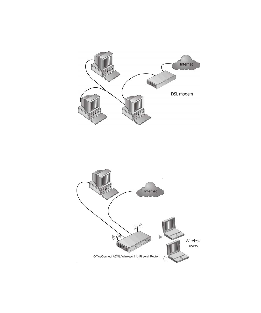
Figure 1
only one computer is connected to the Internet. This computer must
always be powered on for the other computers on the network to access
the Internet.
shows an example network without a Router. In this network,
Page 12
10 CHAPTER 1: INTRODUCING THE ROUTER
Figure 1 Example Network Without a Router
When you use the Router in your network (Figure 2), it becomes your
connection to the Internet. Connections can be made directly to the
Router, or to an OfficeConnect Switch or Hub, expanding the number of
computers you can have in your network.
Figure 2 Example Network Using a Firewall Router
Page 13

Router Advantages The advantages of the Router include:
■ Shared Internet connection for both wired and wireless computers
■ High speed 802.11g wireless networking
■ No need for a dedicated, “always on” computer serving as your
Internet connection
■ Cross-platform operation for compatibility with Windows, Unix and
Macintosh computers
■ Easy-to-use, Web-based setup and configuration
■ Provides centralization of all network address settings (DHCP)
■ Acts as a Virtual server to enable remote access to Web, FTP, and other
services on your network
■ Security — Firewall protection against Internet hacker attacks and
encryption to protect wireless network traffic
Package Contents The Router kit includes the following items:
Router Advantages 11
■ One OfficeConnect ADSL Wireless 11g Firewall Router
■ One power adapter for use with the Router
■ Four rubber feet
■ One Telephone Cable
■ One CD-ROM containing this User Guide
■ Installation Guide
■ One Support and Safety Information Sheet
■ One Warranty Flyer
If any of these items are missing or damaged, please contact your retailer.
Page 14
12 CHAPTER 1: INTRODUCING THE ROUTER
Minimum System and Component Requirements
Your Router requires that the computer(s) and components in your
network be configured with at least the following:
■ A computer with an operating system that supports TCP/IP
networking protocols (for example Windows 98/NT/Me/2000/XP, Unix,
Mac OS 8.5 or higher).
■ An Ethernet 10 Mbps or 10/100 Mbps NIC for each computer to be
connected to the four-port switch on your Router.
■ An 802.11b or 802.11g wireless NIC.
■ An active ADSL subscription and connection.
■ A Web browser that supports JavaScript, such as Netscape 4.7 or
higher, Internet Explorer 5.0 or higher, or Mozilla 1.2.1 or higher.
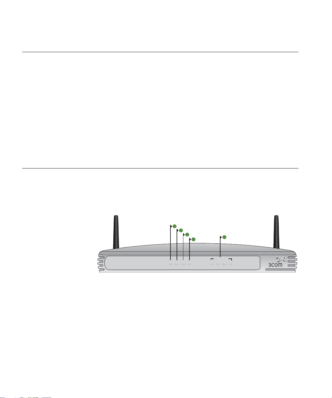
Front Panel The front panel of the Router contains a series of indicator lights (LEDs)
that help describe the state of various networking and connection
operations.
Figure 3 Router - Front Panel
1
2
3
4
5
3CRWDR100A-72
OfficeConnect ADSL Wireless 11g Firewall Router
Power SYNC Online WLAN 1 2 3 4
LAN Status
Green = 100M, Yellow = 10M, Flash = Activity
1Power LED
Green
Indicates that the Router is powered on.
2SYNC LED
Green
If the LED is on it indicates that DSL connection is present. This LED
flashes during configuration at power up.
Page 15
Rear Panel 13
3Online LED
Green
If this LED is on, your username/password has been authenticated
successfully with your ISP.
4 Wireless LAN (WLAN) Status LED
Green
If the LED is on it indicates that wireless networking is enabled. If the LED
is flashing, the link is OK and data is being transmitted or received. If the
LED is off, the Wireless LAN has been disabled in the Router, or there is a
problem. Refer to Chapter 6
“Troubleshooting”.
5 LAN Status LEDs
Green
If the LED is on, the link between the port and the next piece of network
equipment is OK. If the LED is flashing, the link is OK and data is being
transmitted or received. If the LED is off, nothing is connected, or the
connected device is switched off, or there is a problem with the
connection (refer to Chapter 6
“Troubleshooting”). The port will
automatically adjust to the correct speed and duplex.
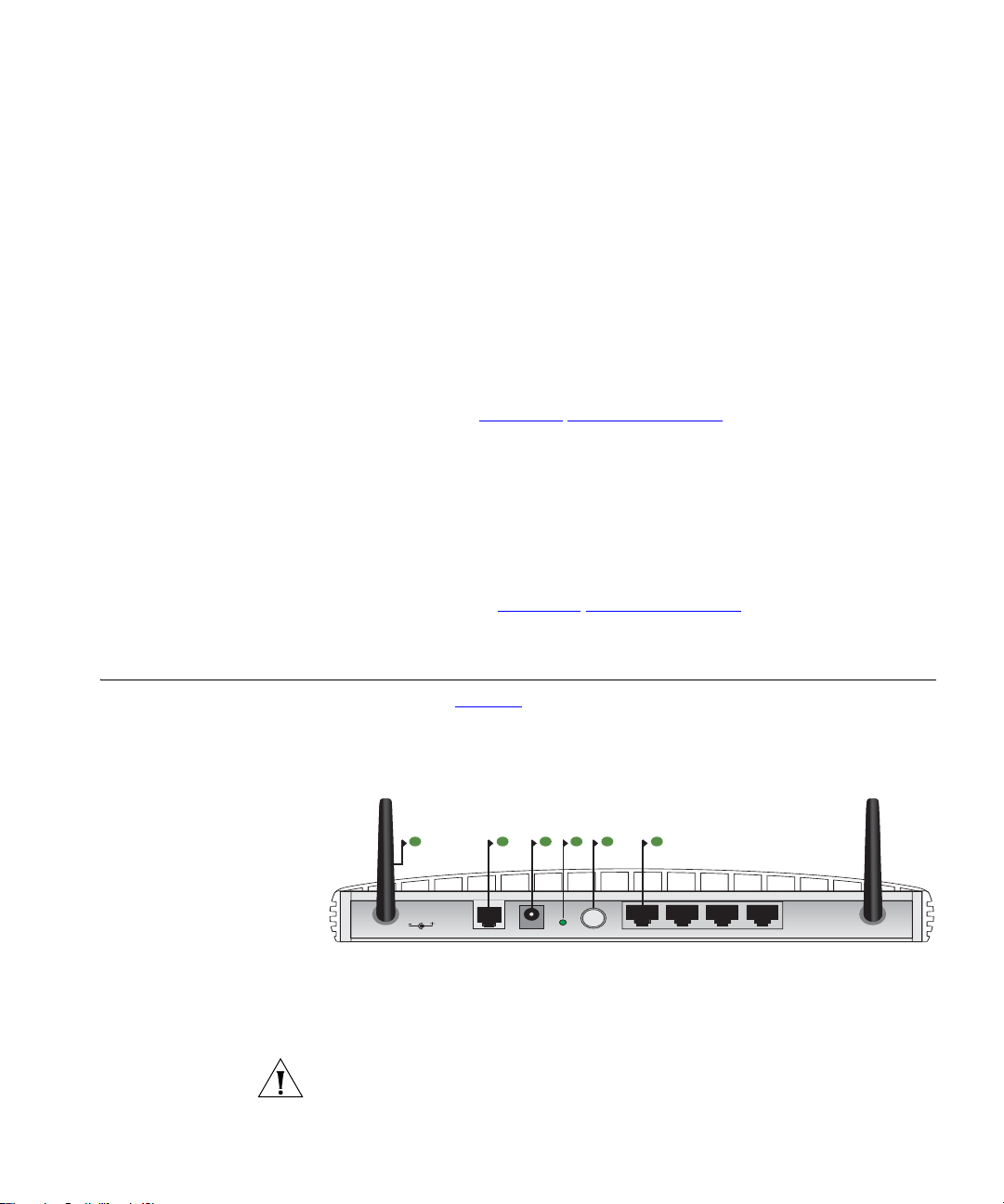
Rear Panel The rear panel (Figure 4) of the Router contains four LAN ports, one ADSL
port, a reset button, a power switch, and a power adapter socket.
Figure 4 Router - Rear Panel
7 98 11106
12 VDC
1A MAX
6 Wireless Antennae
The antennae on the product should be placed in a ‘V’ position when
initially installed.
CAUTION: Do not force the antennae beyond their mechanical stops.
Rotating the antennae further may cause damage.
ADSL ResetPower LAN4 LAN3 LAN2 LAN1
Page 16

14 CHAPTER 1: INTRODUCING THE ROUTER
7ADSL Port
Using the RJ11 cable provided, you should connect your Router to the
telephone socket via a splitter.
8 Power Adapter Socket
Only use the power adapter that is supplied with this Router. Do not use
any other adapter.
9 Reset Button
If you want to reset your Router to factory default settings, and cannot
access the web management interface (for example, due to a lost
password), then you may use this button. Refer to “Forgotten Password
and Reset to Factory Defaults” on page 84 for further details.
10 Power Switch
Push this switch to the “in” position to turn the unit on. In the “out”
position, the unit is off.
11 Ethernet Ports
Using suitable RJ45 cables, you can connect your Router to a computer,
or to any other piece of equipment that has an Ethernet connection (for
example, a hub or a switch). These ports have an automatic MDI/MDIX
feature, which means either straight-through or a crossover cable can be
used.
Page 17

INSTALLING THE ROUTER
2
Introduction This chapter will guide you through a basic installation of the Router,
including:
■ Connecting the Router to the Internet.
■ Connecting the Router to your network.
■ Setting up your computers for networking with the Router.
Safety Information Please note the following:
Positioning the Router
WARNING: Please read the “Safety Information”
before you start.
VORSICHT: Bitte lesen Sie den Abschnitt “Wichtige Sicherheitshinweise”
sorgfältig durch, bevor Sie das Gerät einschalten.
AVERTISSEMENT: Veuillez lire attentivement la section “Consignes
importantes de sécurité” avant de mettre en route.
You should place the Router in a location that:
■ is conveniently located for connection to the telephone socket.
■ is centrally located to the wireless computers that will connect to the
Router. A suitable location might be on top of a high shelf or similar
furniture to optimize wireless connections to computers in both
horizontal and vertical directions, allowing wider coverage.
■ allows convenient connection to the computers that will be connected
to the four LAN ports on the rear panel, if desired.
■ allows easy viewing of the front panel LED indicator lights, and access
to the rear panel connectors, if necessary.
section in Appendix C
Page 18

16 CHAPTER 2: INSTALLING THE ROUTER
When positioning your Router, ensure:
■ It is out of direct sunlight and away from sources of heat.
■ Cabling is away from power lines, fluorescent lighting fixtures, and
sources of electrical noise such as radios, transmitters and broadband
amplifiers.
■ Water or moisture cannot enter the case of the unit.
■ Air flow around the unit and through the vents in the side of the case
is not restricted. 3Com recommends you provide a minimum of
25 mm (1 in.) clearance.
Using the Rubber
Powering Up the Router
Connecting the Router
Use the four self-adhesive rubber feet to prevent your Router from
Feet
moving around on your desk or when stacking with flat top units. Only
stick the feet to the marked areas at each corner of the underside of your
Router.
To power up the Router:
1 Plug the power adapter into the power adapter socket located on the
back panel of the Router.
2 Plug the power adapter into a standard electrical wall socket.
3 Press the power button located on the back of the Router.
The first step for installing your Router is to physically connect it to the
telephone socket and then connect it to a computer in order to be able to
access the Internet. See Figure 5
:
Page 19
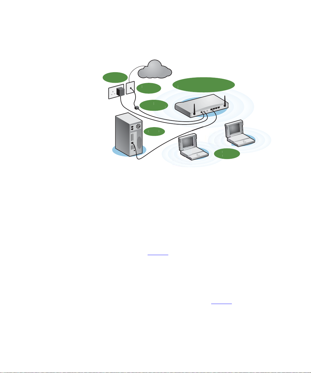
Figure 5 Connecting the Router
ock
C
ess
Users
r
Connecting the Router 17
Power
Supply Unit
Internet
Telephone
Socket
Splitter/
Microfilter Bl
Your P
3Com OfficeConnect
DSL Wireless 11g Firewall Route
Wirel
1 Run the provided telephone cable from the wall jack providing ADSL
service to the ADSL port on your ADSL Router. When inserting an ADSL
RJ-11 plug, be sure the tab on the plug clicks into position to ensure that
it is properly seated. If you are using splitterless ADSL service, add
low-pass filters between the ADSL wall jack and your telephones. (These
filters pass voice signals through but filter data signals out.)
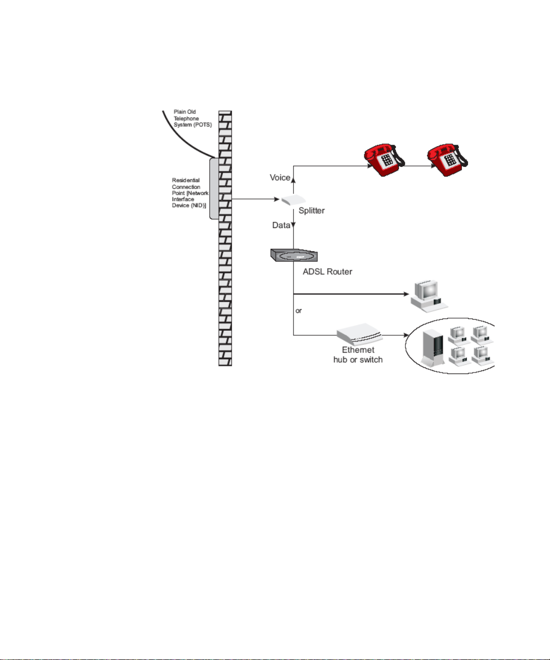
2 Then:
■ If you are using a full-rate (G.dmt) connection, your service provider
will attach the outside ADSL line to a data/voice splitter. In this case
you can connect your phones and computer directly to the splitter as
shown below (Figure 6
):
or
■ If you are using a splitterless (G.lite) connection, then your service
provider will attach the outside ADSL line directly to your phone
system. In this case you can connect your phones and computer
directly to the incoming ADSL line, but you will have to add low-pass
filters to your phones as shown below (Figure 7
)
Page 20
18 CHAPTER 2: INSTALLING THE ROUTER
Figure 6 Installing with a splitter
Page 21
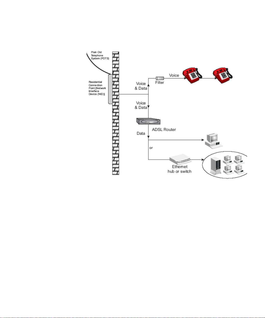
Figure 7 Installing without a splitter
Connecting the Router 19
You have now completed the hardware installation of your Router. Next
you need to set up your computers so that they can make use of the
Router to communicate with the Internet.
3Com recommends that you perform the initial Router configuration
from a computer that is directly connected to one of the LAN ports.
If you configure the Router from a wireless computer, note that you may
lose contact with the Router if you change the wireless configuration.
To communicate wirelessly with your Router, your wireless NIC should be
set as follows:
■ Encryption — none
■ SSID — 3Com
■ Channel — 11
Page 22

20 CHAPTER 2: INSTALLING THE ROUTER
Page 23

3
Obtaining an IP Address Automatically
Windows 2000 If you are using a Windows 2000-based computer, use the following
SETTING UP YOUR COMPUTERS
The Router has the ability to dynamically allocate network addresses to
the computers on your network, using DHCP. However, your computers
need to be configured correctly for this to take place. To change the
configuration of your computers to allow this, follow the instructions in
this chapter.
procedure to change your TCP/IP settings:
1 From the Windows Start Menu, select Settings > Control Panel.
2 Double click on Network and Dial-Up Connections.
3 Double click on Local Area Connection.
4 Click on Properties.
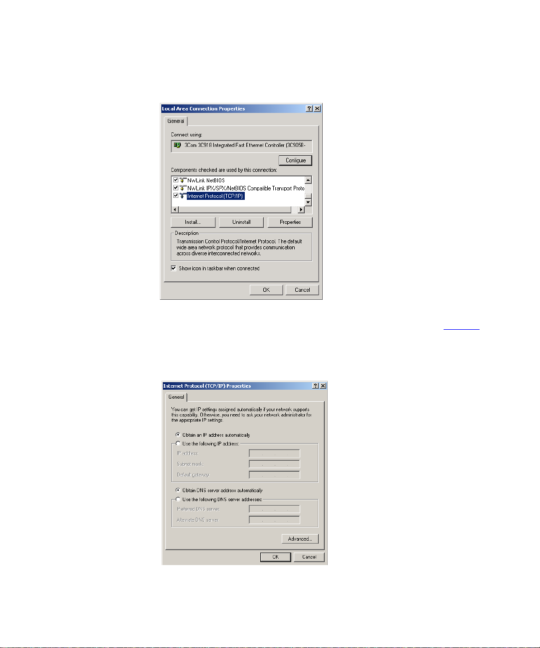
5 A screen similar to Figure 8
TCP/IP and click on Properties.
should be displayed. Select Internet Protocol
Page 24
22 CHAPTER 3: SETTING UP YOUR COMPUTERS
Figure 8 Local Area Properties Screen
6 Ensure that the options Obtain an IP Address automatically, and Obtain
DNS server address automatically are both selected as shown in Figure 9
Click OK.
.
Figure 9 Internet Protocol (TCP/IP) Properties Screen
7 Restart your computer.
Page 25

Windows XP
Windows 98/ME
Obtaining an IP Address Automatically 23
1 From the Windows Start menu, select Control Panel.
2 Click on Network and Internet Connections.
3 Click on the Network Connections icon.
4 Double click on LAN or High Speed Connection icon. A screen titled Local
Area Connection Status will appear.
5 Select Internet Protocol TCP/IP and click on Properties.
6 Ensure that the options Obtain an IP Address automatically, and Obtain
DNS servers automatically are both selected. Click OK.
7 Restart your computer.
1 From the Windows Start Menu, select Settings > Control Panel.
2 Double click on Network. Select the TCP/IP item for your network card
and click on Properties.
3 In the TCP/IP dialog, select the IP Address tab, and ensure that Obtain IP
address automatically is selected. Click OK.
Macintosh If you are using a Macintosh computer, use the following procedure to
change your TCP/IP settings:
1 From the desktop, select Apple Menu, Control Panels, and TCP/IP.
2 In the TCP/IP control panel, set Connect Via: to Ethernet.
3 In the TCP/IP control panel, set Configure: to Using DHCP Server.
4 Close the TCP/IP dialog box, and save your changes.
5 Restart your computer.
Page 26

24 CHAPTER 3: SETTING UP YOUR COMPUTERS
Disabling PPPoE and PPTP Client Software
If you have PPPoE client software installed on your computer, you will
need to disable it. To do this:
1 From the Windows Start menu, select Settings > Control Panel.
2 Double click on Internet Options.
3 Select the Connections Tab. A screen similar to Figure 10
displayed.
4 Select the Never Dial a Connection option.
Figure 10 Internet Properties Screen
should be
Disabling Web Proxy
You may want to remove the PPPoE client software from your computer
to free resources, as it is not required for use with the Router.
Ensure that you do not have a web proxy enabled on your computer.
Go to the Control Panel and click on Internet Options. Select the
Connections tab and click LAN Settings at the bottom. Make sure that
the Use Proxy Server option is unchecked.
Page 27
4
RUNNING THE SETUP WIZARD
Accessing the Setup Wizard
The Router setup program is Web-based, which means that it is accessed
through your Web browser (Netscape Navigator 4.7 or higher, Internet
Explorer 5.0 or higher, or Mozilla 1.2.1 or higher).
To use the Setup Wizard:
1 Ensure that you have at least one computer connected to the Router.
Refer to Chapter 2
2 Launch your Web browser on the computer.
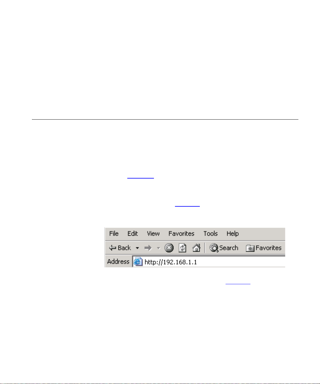
3 Enter the following URL in the location or address field of your browser:
http://192.168.1.1 (Figure 11
Figure 11 Web Browser Location Field (Factory Default)
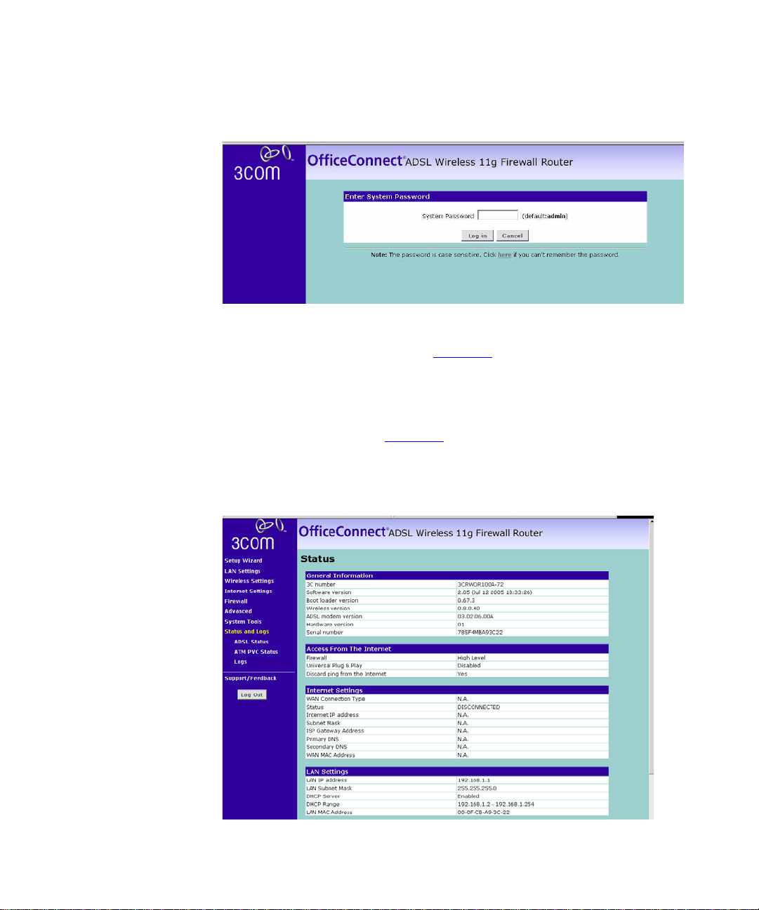
4 To log in as an administrator, enter the password (the default password is
admin) in the Password field and click Log in (Figure 12
for details on how to do this.
). The Login screen displays.
).
Page 28
26 CHAPTER 4: RUNNING THE SETUP WIZARD
Figure 12 Router Login Screen
5 When you have logged in either:
■ The Status screen will appear (Figure 13). Select Setup Wizard from
the menu.
or
■ If your Router has not been configured before, the Wizard will launch
automatically (refer to Figure 14
).
6 You will be guided step by step through a basic setup procedure.
Figure 13 Status Screen
Page 29
Accessing the Setup Wizard 27
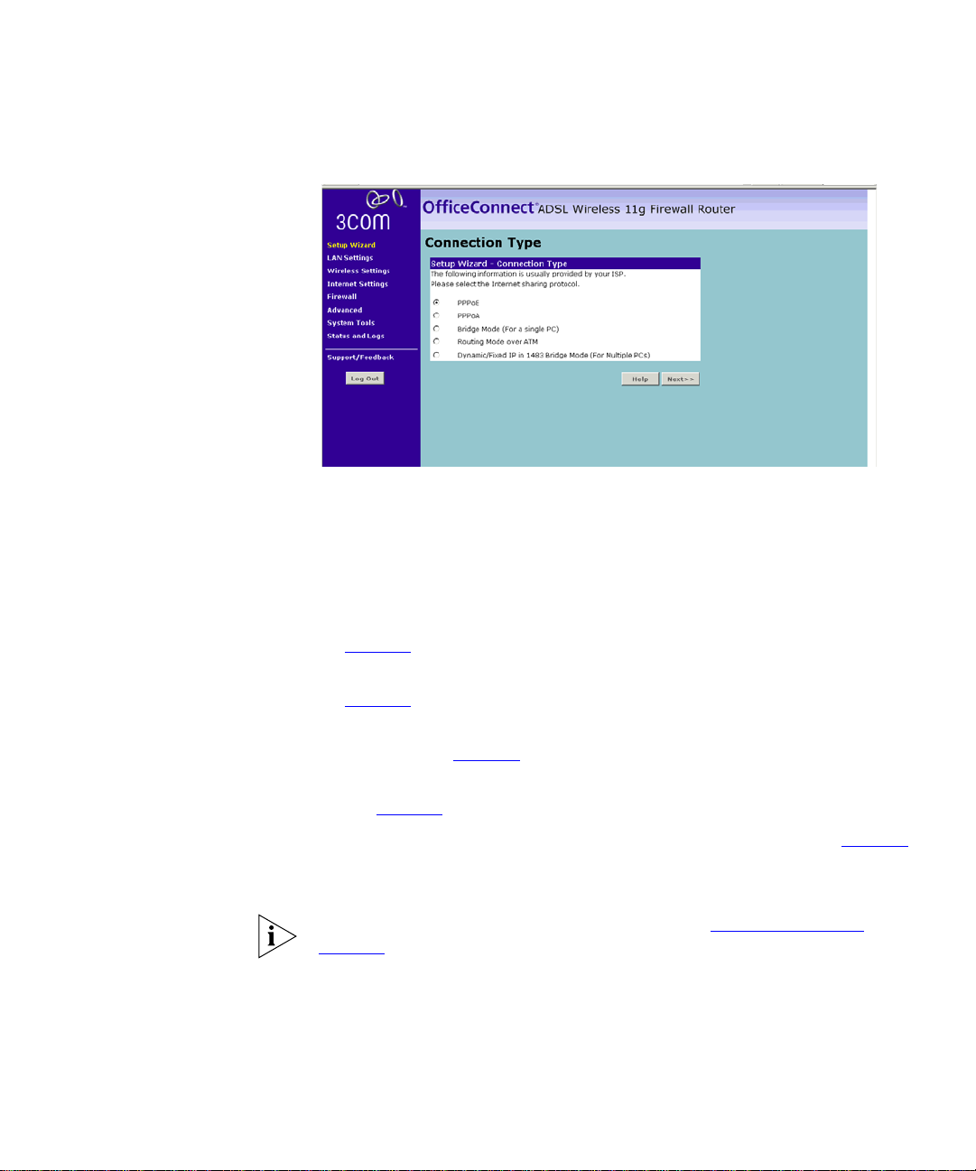
Setup Wizard -
Connection Type
Figure 14 Connection Type Screen
The Connection Type screen allows you to set up the Router for the type
of Internet connection you have. Before setting up your connection type,
have your account information from your ISP ready.
Select a DSL mode from the following:
■ PPPoE — PPP over Ethernet, providing routing for multiple PCs, see
page 28
■ PPPoA — PPP over ATM, providing routing for multiple PCs, see
page 29
■ Bridge Mode (for a single PC) — RFC1483 Bridged Mode, for single
PCs only, see page 31
■ Routing Mode over ATM — RFC1483 Routed Mode, for multiple PCs,
see page 32
■ Dynamic/Fixed IP in 1483 Bridge Mode (for multiple PCs), see page 33
and click Next.
For further information on selecting a mode see “Internet Settings”
page 46
.
on
Page 30
28 CHAPTER 4: RUNNING THE SETUP WIZARD
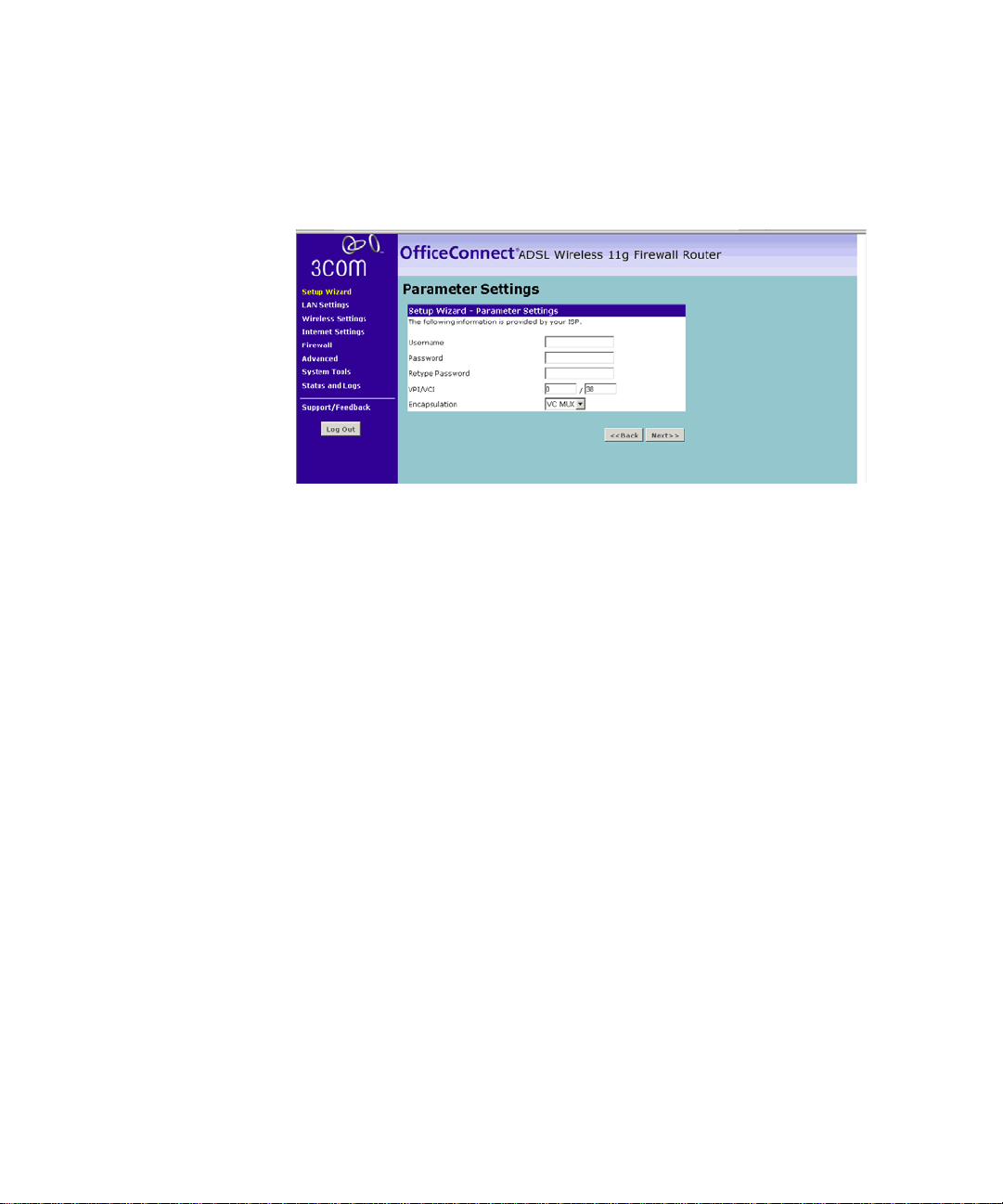
PPPoE Mode
Figure 15 PPPoE Screen
To set up the router for use with a PPP over Ethernet (PPPoE) connection,
use the following procedure:
1 Enter your PPP over Ethernet user name in the Username text box.
2 Enter your PPP over Ethernet password in the Password text box.
3 Re-type your PPP over Ethernet password in the Retype Password text
box.
4 Enter your VPI and VCI information in the VPI/VCI text boxes.
5 Select the encapsulation type (LLC or VC MUX) in the Encapsulation
drop-down list. This information will have been provided to you by your
ISP.
6 Check all of your settings, and then click Next. The Wireless Settings
screen is displayed.
Page 31

Accessing the Setup Wizard 29
Figure 16 Wireless Settings Screen
7 Set the Wireless Channel you want to use from the Channel drop-down
list.
8 Specify the SSID to be used by your Wireless Network in the SSID field. If
there are other wireless networks in your area, you should give your
wireless network a unique name.
PPPoA Mode
Figure 17 PPPoA Screen
To set up the router for use with a PPP over ATM (PPPoA) connection, use
the following procedure:
1 Enter your PPP over ATM user name in the Username text box.
2 Enter your PPP over ATM password in the Password text box.
3 Re-type your PPP over ATM password in the Retype Password text box.
4 Enter your VPI and VCI information in the VPI/VCI text boxes.
Page 32

30 CHAPTER 4: RUNNING THE SETUP WIZARD
5 Select the encapsulation type (LLC or VC MUX) in the Encapsulation
drop-down list. This information will have been provided to you by your
ISP.
6 Check all of your settings, and then click Next. The Wireless Settings
screen is displayed.
Figure 18 Wireless Settings Screen
7 Set the Wireless Channel you want to use from the Channel drop-down
list.
8 Specify the SSID to be used by your Wireless Network in the SSID field. If
there are other wireless networks in your area, you should give your
wireless network a unique name.
Page 33

Accessing the Setup Wizard 31
Bridge Mode (for a single PC) (RFC 1483 Bridged Mode)
To set up the Router for use with an RFC1483 bridged connection:
Figure 19 Bridged Mode Configuration Screen
1 Enter your VPI and VCI information in the VPI/VCI text boxes.
2 Select the encapsulation type (LLC or VC MUX) in the Encapsulation
drop-down list. This information will have been provided to you by your
ISP.
3 Check all of your settings, and then click Next. The Wireless Settings
screen is displayed.
Figure 20 Wireless Settings Screen
4 Set the Wireless Channel you want to use from the Channel drop-down
list.
5 Specify the SSID to be used by your Wireless Network in the SSID field. If
there are other wireless networks in your area, you should give your
wireless network a unique name.
Page 34

32 CHAPTER 4: RUNNING THE SETUP WIZARD
Routing Mode over ATM (RFC 1483 Routed Mode)
To set up the Router for use with an RFC1483 routed connection:
Figure 21 Routing Mode Screen
1 Enter your Internet IP address in the WAN IP text box.
2 Enter the subnet mask in the Subnet Mask text box.
3 Enter the default router in the Default Gateway text box.
4 Enter the DNS address in the DNS text box.
5 Enter your VPI and VCI information in the VPI/VCI text boxes.
6 Select the encapsulation type (LLC or VC MUX) in the Encapsulation
drop-down list. This information will have been provided to you by your
ISP.
7 Check all of your settings, and then click Next.The Wireless Settings
screen is displayed.
Figure 22 Wireless Settings Screen
Page 35

Accessing the Setup Wizard 33
8 Set the Wireless Channel you want to use from the Channel drop-down
list.
9 Specify the SSID to be used by your Wireless Network in the SSID field. If
there are other wireless networks in your area, you should give your
wireless network a unique name.
Dynamic/Fixed IP in 1483 Bridge Mode (For Multiple PCs)
For bridge mode to work, you need to assign an IP address to the Router.
You can either configure the Router to obtain an IP address automatically
from a DHCP server or assign a fixed or static IP address to it.
Figure 23 Dynamic/Fixed IP for Bridge Mode Screen
To obtain an IP address automatically from a DHCP server:
Check the Get WAN IP By DCHP field, and then click Next. The Wireless
Settings screen is displayed.
To assign a fixed IP address:
1 Enter your Internet IP address in the WAN IP text box.
2 Enter the subnet mask in the Subnet Mask text box.
3 Enter the default router in the Default Gateway text box.
4 Enter the DNS address in the DNS text box.
5 Enter your VPI and VCI information in the VPI/VCI text boxes.
6 Select the encapsulation type (LLC or VC MUX) in the Encapsulation
drop-down list. This information will have been provided to you by your
ISP.
7 Check all of your settings, and then click Next. The Wireless Settings
screen is displayed.
Page 36

34 CHAPTER 4: RUNNING THE SETUP WIZARD
Figure 24 Wireless Settings Screen
8 Set the Wireless Channel you want to use from the Channel drop-down
list.
9 Specify the SSID to be used by your Wireless Network in the SSID field. If
there are other wireless networks in your area, you should give your
wireless network a unique name.
Configuration Summary
Figure 25 Configuration Summary Screen
When you complete the Setup Wizard, a configuration summary will
display. Verify the configuration information of the Router and then click
Apply to save your settings. 3Com recommends that you print this page
for your records.
Your Router is now configured and ready for use.
See Chapter 5
for a detailed description of the Router configuration.
Page 37

5
CONFIGURING THE ROUTER
Navigating Through the Router Configuration Pages
Main Menu At the left side of all screens is a main menu, as shown in Figure 26
Status Screen The Status screen allows you to view a summary of the Router
Status Figure 26 Status Screen
This chapter describes all the screens available through the Router
configuration pages, and is provided as a reference. To get to the
configuration pages, browse to the Router by entering the URL in the
location bar of your browser. The default URL is http://192.168.1.1
but if you changed the Router LAN IP address during initial configuration,
use the new IP address instead. When you have browsed to the Router,
log in using your system password (default password is admin).
page 35
appear in the main part of the screen.
configuration, including the current Router status.
. When you click on a topic from the main menu, that page will
on
Page 38

36 CHAPTER 5: CONFIGURING THE ROUTER
LAN Setup Your Router is equipped with a DHCP server that will automatically assign
IP addresses to each computer on your network. The factory default
settings for the DHCP server will work in most any application. If you
need to make changes to the settings, you can do so.
The changes that you can make are:
■ Change the Internal IP address of the Router. The default is
192.168.1.1
■ Change the Subnet Mask. The default is 255.255.255.0
■ Enable/Disable the DHCP Server Function. Default is ON (Enabled)
■ Specify the Starting and Ending IP Pool Address. Default is Starting: 2 /
Ending: 254
■ Specify the IP address Lease Time. Default is Half day
■ Specify a local Domain Name. Default is NONE
To make changes, click LAN Settings on the main menu.
The Router will also provide you with a list of all client computers
connected to the network.
Page 39

LAN Setup 37
LAN Settings The LAN Settings screen is used to specify the LAN IP address of your
Router, and to configure the DHCP server.
Figure 27 LAN Settings Screen
1 Select LAN Settings and then specify the Router IP Address and Subnet
Mask in the appropriate fields. The default IP address of the Router is
192.168.1.1.
2 If you want to use the Router as a DHCP Server, click in the On check
option.
3 If you need to, you can change the range of addresses given out by the
Router by changing the IP Pool Start Address and IP Pool End Address
fields.
4 Specify the DHCP Lease time by selecting the required value from the
Lease Time drop down list. The lease time is the length of time the DHCP
server will reserve the IP address for each computer
5 Specify the Local Domain Name for your network.
This step is optional.
6 Check all of your settings, and then click Apply.
Page 40

38 CHAPTER 5: CONFIGURING THE ROUTER
DHCP Clients List
The DHCP Clients List provides details on the devices that have received IP
addresses from the Router. The list is only created when the Router is set
up as a DHCP server. For each device that is connected to the LAN the
following information is displayed:
■ IP address — The Internet Protocol (IP) address issued to the client
machine.
■ Host Name — The client machine’s host name, if configured.
■ MAC Address — The Media Access Control (MAC) address of the
client’s network card.
■ Client Type — Whether the client is connected to the Router by wired
or wireless connection.
As you connect more devices, the client list will grow to a maximum
number of 253 clients.
From this section of the screen, you can do the following:
■ In the table, check the Fix text box to permanently fix the IP address.
■ In the table, click Release to release the displayed IP address.
■ Click New to allocate an IP address to a MAC address. If you click
New, a screen similar to that shown in Figure 28
will be displayed.
Enter the required details and click Apply to save your settings.
Figure 28 Editing DHCP Clients List Screen
The DHCP server will give out addresses to both wired and wireless
clients.
Page 41

Wireless Settings 39
Wireless Settings From these pages, you can configure the settings for wireless
connections.
Figure 29 Wireless Settings Screen
This screen allows you to enable or disable the wireless section of your
LAN. When disabled, no wireless PCs can gain access to either the
Internet or other PCs on your Wired or Wireless LAN through this Router.
Select the required setting, and press Apply.
Configuring Wireless Click Configuration on the left-hand menu, the Wireless Configuration
Screen displays.
Figure 30 Wireless Configuration Screen
Page 42

40 CHAPTER 5: CONFIGURING THE ROUTER
To enable Wireless function:
1 Select the Wireless Channel you want to use from the Channel
drop-down list.
2 Specify the SSID to be used by your Wireless Network in the SSID field. If
there are other wireless networks in your area, you should give your
wireless network a unique name.
3 Enable or disable SSID Broadcast.
A feature of many wireless network adapters is that a computer's SSID
can be set to ANY, which means it looks randomly for any existing
wireless network. The available networks are then displayed in a site
survey, and your computer can select a network. By clicking disable, you
can block this random search, and set the computer's SSID to a specific
network (for example, WLAN). This increases network security. If you
decide to enable SSID Broadcast, ensure that you know the name of your
network first.
4 In the Wireless Mode drop down list, select whether your router will
operate in 11b mode only, 11g mode only, or mixed 11b and 11g.
5 Click Apply.
Encryption This feature prevents any non-authorized party from reading or changing
your data over the wireless network.
Figure 31 Encryption Screen
From this screen, you can select the wireless security mode that you want
to use. There are five selections:
■ Disabled (see page 41)
Page 43

Wireless Settings 41
■ WPA-PSK (no Server) (see page 41)
■ 128-bit WEP (see page 42)
■ 64-bit WEP (see page 43)
■ WPA (with RADIUS Server) (see page 44)
Select the required value from the drop down list, and press Apply.
Disabled
In this mode, wireless transmissions will not be encrypted, and will be
visible to everyone. However, when setting up or debugging wireless
networks, it is often useful to use this security mode.
WPA-PSK (no server)
WPA (WiFi Protected Access) provides dynamic key changes and
constitutes the best security solution. In a wireless network where not all
devices support WPA, WEP (Wired Equivalent Privacy) should be used.
Figure 32 WPA-PSK (no server) Screen
To enable WPA-PSK:
1 Enter the pre-shared key in the Pre-shared Key (PSK) field. The pre-shared
key is a password, in the form of a word, phrase or series of letters and
numbers. The key must be between 8 and 63 characters long and can
include spaces and symbols.
Note that each client that connects to the network must use the same
key.
Page 44

42 CHAPTER 5: CONFIGURING THE ROUTER
2 Optionally, check the Hide PSK check box, if you want the key that you
enter to be shown on the screen as a series of asterisks (*).
3 Click Apply.
128-bit WEP
WEP is the basic mechanism to transmit your data securely over the
wireless network. Matching encryption keys must be setup on your
Router and wireless client devices to use WEP.
Figure 33 128-bit WEP Screen
To enable 128-bit WEP:
1 You can enter the 128-bit WEP key manually:
■ enter your WEP key as 13 pairs of hex digits (0-9, A-F).
Or you can generate the 128-bit WEP key automatically:
■ enter a memorable passphrase in the Passphrase box, and then
click Generate to generate the hex keys from the passphrase.
The WEP keys on each device on the wireless network must be identical.
In 128-bit WEP mode, only one WEP key (key 1) can be specified.
2 Click Apply.
Page 45

Wireless Settings 43
64-bit WEP
WEP is the basic mechanism to transmit your data securely over the
wireless network. Matching encryption keys must be setup on your
Router and wireless client devices to use WEP.
Figure 34 64-bit WEP Screen
To enable 64-bit WEP:
1 Manually enter the key:
■ enter the WEP key as 5 pairs of hex digits (0-9, A-F).
Automatically generate the key:
■ enter a memorable passphrase in the Passphrase box, and then click
Generate to generate the hex keys from the passphrase.
For 64-bit WEP, you can enter up to four keys, in the fields Key 1 to Key 4.
The radio button on the left hand side selects the key that is used in
transmitting data.
Note that all four WEP keys on each device in the wireless network must
be identical.
2 Click Apply.
Page 46

44 CHAPTER 5: CONFIGURING THE ROUTER
WPA (with RADIUS Server)
WPA (WiFi Protected Access) provides dynamic key changes and
constitutes the best security solution. On a wireless network where not all
devices support WPA, WEP (Wired Equivalent Privacy) should be used.
Wireless Protected Access using a server to distribute keys to the clients,
and this function requires that a Radius server is running on the network.
Figure 35 WPA (with RADIUS Server) Screen
To enable WPA with Radius server:
1 Enter the IP address of the RADIUS server on your network into the
RADIUS Server field.
2 Enter the port that the RADIUS server is operating on in the RADIUS Port
field.
3 Enter the key for the RADIUS server in the RADIUS Key field.
4 By default, the WPA keys are changed every hour, but if you want to
change this you can do so by specifying the required time in the Re-key
Interval field, in minutes.
5 Click Apply.
Page 47

Wireless Settings 45
Wireless WDS Settings
The Router supports WDS (Wireless Distribution System). WDS enables
one or more Access Points to rebroadcast received signals to extend
range and reach, though this can affect the overall throughput of data.
Figure 36 Wireless WDS Settings Screen
To enable wireless repeating:
1 Check the Enable WDS check box.
2 Enter the MAC address(es) of one or more access points in the AP MAC
Address table.
3 Click Apply.
To refresh the list of available access points, click Rescan Wireless
Networking.
Page 48

46 CHAPTER 5: CONFIGURING THE ROUTER
Internet Settings From these pages, you can configure the settings for your DSL
connection.
Connection Type The Internet Settings screen is used to configure the parameters for your
DSL connection. The information necessary to complete these screens
should be obtained from your ISP. Check with your ISP as for what type of
connection you should choose.
Figure 37 Internet Settings Screen
There are six options available for the DSL connection mode:
■ PPPoE — PPP over Ethernet, providing routing for multiple PCs (see
page 47
■ PPPoA — PPP over ATM, providing routing for multiple PCs (see
page 49
■ Bridge Mode — RFC1483 Bridged Mode, for single PCs only (see
page 51
■ Routing Mode over ATM — RFC1483 Routed Mode, for multiple PCs
(see page 52
■ Dynamic/Fixed IP in 1483 Bridge Mode (for multiple PCs) (see page 53)
■ Disable — To disable the Internet connection function (see page 55)
)
)
)
)
Click Edit to set the detail settings.
Page 49

Internet Settings 47
PPPoE
PPP over Ethernet, providing routing for multiple PCs. To configure this
page correctly, you should obtain the information on this page from your
ISP.
Figure 38 PPPoE Settings Screen
1 Select PPPoE from the Protocol drop-down menu.
2 Then enter the IP address and Subnet Mask information provided by your
ISP into the IP address and Subnet Mask fields.
3 Enter the VPI and VCI parameters provided to you by your ISP in the VPI
and VCI fields.
4 Select the encapsulation type (LLC or VC MUX) in the Encapsulation field.
This information will have been provided to you by your ISP.
5 Select the type of Quality of Service (CBR, UBR or VBR) in the QoS field.
■ CBR (constant bit rate): the CBR service class is intended for
real-time applications, for example, those requiring tightly
constrained delay and delay variation, such as voice and video
applications. The consistent availability of a fixed quantity of
bandwidth is considered appropriate for CBR service.
■ UBR (unspecified bit rate): the UBR service class is intended for
delay-tolerant or non-real-time applications, for example, those
which do not require tightly constrained delay and delay variation,
such as traditional computer communications applications. The
UBR service may be considered as "best effort service".
Page 50

48 CHAPTER 5: CONFIGURING THE ROUTER
■ VBR (variable bit rate): QoS class defined by the ATM Forum for
ATM networks. VBR is subdivided into a real time (RT) class and
non-real time (NRT) class. VBR (RT) is used for connections in which
there is a fixed timing relationship between samples. VBR (NRT) is
used for connections in which there is no fixed timing relationship
between samples, but that still need a guaranteed QoS. Compare
with ABR, CBR, and UBR.
6 Enter the PCR/SCR/MBS values.
7 Select the connection type from the Connect Type drop-down menu.
■ Always Connected means that Internet connection to your ISP is
always on.
■ Auto - Triggered by Traffic means your Router will automatically
connect to your ISP every time a PC needs to access the Internet.
■ Manual - Start in Disconnected means that after re-booting the
Router, the Internet connection will need to be re-established
manually by the user.
■ Manual - Start in Connected means that after re-booting the
Router, it will automatically establish connection to your ISP.
■ Manual - Start in Last State means that after re-booting the Router,
the Internet connection will stay in the previous condition before
the reboot.
8 If you want your Router to automatically disconnect from the Internet
after a period of inactivity, specify a time in the Idle Time (Minutes) field.
Enter a value of 0 to disable this timeout.
9 Enter the User Name assigned to you by your ISP in the User Name field.
And enter the password assigned to you by your ISP in the Password field.
Re-enter your password in the Confirm Password field.
10 Enter the MTU value supplied by your ISP. If you do not know this, leave it
at the default value.
11 Click Apply.
Page 51

Internet Settings 49
PPPoA
PPP over ATM, this is a popular choice among European DSL providers. To
configure this page correctly, you should obtain the information on this
page from your ISP.
Figure 39 PPPoA Settings Screen
1 Select PPPoA from the Protocol drop-down menu.
2 Enter the VPI and VCI parameters provided to you by your ISP in the VPI
and VCI fields.
3 Select the encapsulation type (LLC or VC MUX) in the Encapsulation Type
field. This information is provided to you by your ISP.
4 Select the type of Quality of Service (CBR, UBR or VBR) in the QoS field.
■ CBR (constant bit rate): the CBR service class is intended for
real-time applications, for example, those requiring tightly
constrained delay and delay variation, such as voice and video
applications. The consistent availability of a fixed quantity of
bandwidth is considered appropriate for CBR service.
■ UBR (unspecified bit rate): the UBR service class is intended for
delay-tolerant or non-real-time applications, for example, those
which do not require tightly constrained delay and delay variation,
such as traditional computer communications applications. The
UBR service may be considered as "best effort service".
■ VBR (variable bit rate): QoS class defined by the ATM Forum for
ATM networks. VBR is subdivided into a real time (RT) class and
Page 52

50 CHAPTER 5: CONFIGURING THE ROUTER
non-real time (NRT) class. VBR (RT) is used for connections in which
there is a fixed timing relationship between samples. VBR (NRT) is
used for connections in which there is no fixed timing relationship
between samples, but that still need a guaranteed QoS. Compare
with ABR, CBR, and UBR.
5 Enter the PCR/SCR/MBS values.
6 IP assigned by ISP:
■ If your ISP assigns your IP address dynamically then select Yes in the
IP assigned by ISP field and proceed to step 7.
■ If your ISP has assigned you a fixed or static IP address, select No in
the IP assigned by ISP field.
Then enter the IP address and Subnet Mask information provided
by your ISP into the IP address and Subnet Mask fields.
7 Select the connection type from the Connect Type drop-down menu.
■ Always Connected means that Internet connection to your ISP is
always on.
■ Auto - Triggered by Traffic means your Router will automatically
connect to your ISP every time a PC needs to access the Internet.
■ Manual - Start in Disconnected means that after re-booting the
Router, the Internet connection will need to be re-established
manually by the user.
■ Manual - Start in Connected means that after re-booting the
Router, it will automatically establish connection to your ISP.
■ Manual - Start in Last State means that after re-booting the Router,
the Internet connection will stay in the previous condition before
the reboot.
8 If you want your Router to automatically disconnect from the Internet
after a period of inactivity, specify a time in the Idle Time (Minutes) field.
Enter a value of 0 to disable this timeout.
9 Enter the User Name assigned to you by your ISP in the User Name field.
Enter the password assigned to you by your ISP in the Password field.
Re-enter your password in the Confirm Password field.
10 Enter the MTU value supplied by your ISP. If you do not know this, leave it
at the default value.
11 Click Apply.
Page 53

Internet Settings 51
Bridge Mode (For a Single PC) (RFC 1483 Bridged Mode)
If the ISP limits some specific computers to access Internet, that means
only the traffic to/from these computers will be forwarded and the other
will be filtered. In this case, bridge modem is used to connect to the ISP.
The ISP will generally give one Internet account and limit only one
computer to access the Internet. Check with your ISP to determine if this
mode is used for your DSL connection. To configure this page correctly,
you should also obtain the information on this page from your ISP.
Figure 40 Bridge Mode (For Single PC) Screen
After clicking Edit on the ATM PVC page, the ATM Interface page
appears.
1 Select Bridge Mode from the Protocol drop-down menu.
2 Enter the VPI and VCI parameters provided to you by your ISP in the VPI
and VCI fields.
3 Select the encapsulation type (LLC or VC MUX) in the Encapsulation Type
field. This information will have been provided to you by your ISP.
4 Select the type of Quality of Service that you want from the QoS Class
drop-down menu.
■ CBR (constant bit rate): the CBR service class is intended for
real-time applications, for example, those requiring tightly
constrained delay and delay variation, such as voice and video
applications. The consistent availability of a fixed quantity of
bandwidth is considered appropriate for CBR service.
■ UBR (unspecified bit rate): the UBR service class is intended for
delay-tolerant or non-real-time applications, for example, those
which do not require tightly constrained delay and delay variation,
Page 54

52 CHAPTER 5: CONFIGURING THE ROUTER
such as traditional computer communications applications. The
UBR service may be considered as "best effort service".
■ VBR (variable bit rate): QoS class defined by the ATM Forum for
ATM networks. VBR is subdivided into a real time (RT) class and
non-real time (NRT) class. VBR (RT) is used for connections in which
there is a fixed timing relationship between samples. VBR (NRT) is
used for connections in which there is no fixed timing relationship
between samples, but that still need a guaranteed QoS. Compare
with ABR, CBR, and UBR.
5 Enter the PCR/SCR/MBS values.
6 Click Apply.
Routing Mode over ATM (RFC 1483 Routed Mode)
This mode is commonly used with either dynamic or static IP addressing.
In this mode the WAN ADSL port will be configured with an IP address
provided by the ISP. To configure this page correctly, you should obtain
the information on this page from your ISP.
Figure 41 Routing Mode over ATM Screen
After clicking Edit on the ATM PVC page, the ATM Interface page
appears.
1 Select Routing Mode over ATM from the Protocol drop-down menu.
2 Enter the IP address, Subnet Mask and Default Gateway information
provided by your ISP into the IP address, Subnet Mask and ISP Default
Gateway fields.
3 Enter the VPI and VCI parameters provided to you by your ISP in the VPI
and VCI fields.
Page 55

Internet Settings 53
4 Select the encapsulation type (LLC or VC MUX) in the Encapsulation field.
This information will have been provided to you by your ISP.
5 Select the type of Quality of Service that you want from the QoS Class
drop-down menu.
■ CBR (constant bit rate): the CBR service class is intended for
real-time applications, for example, those requiring tightly
constrained delay and delay variation, such as voice and video
applications. The consistent availability of a fixed quantity of
bandwidth is considered appropriate for CBR service.
■ UBR (unspecified bit rate): the UBR service class is intended for
delay-tolerant or non-real-time applications, for example, those
which do not require tightly constrained delay and delay variation,
such as traditional computer communications applications. The
UBR service may be considered as "best effort service".
■ VBR (variable bit rate): QoS class defined by the ATM Forum for
ATM networks. VBR is subdivided into a real time (RT) class and
non-real time (NRT) class. VBR (RT) is used for connections in which
there is a fixed timing relationship between samples. VBR (NRT) is
used for connections in which there is no fixed timing relationship
between samples, but that still need a guaranteed QoS. Compare
with ABR, CBR, and UBR.
6 Enter the PCR/SCR/MBS values.
7 If your ISP uses DHCP to automatically assign IP addresses, check the
DHCP Client box.
8 Click Apply.
Dynamic/Fixed IP in 1483 Bridge Mode (For Multiple PCs)
Your ISP uses fixed/dynamic IP to provide the Internet connection. To
configure this function correctly, you should obtain the information on
this page from your ISP.
Page 56

54 CHAPTER 5: CONFIGURING THE ROUTER
Figure 42 Dynamic/Fixed IP for Bridge Mode Screen
After clicking Edit on the ATM PVC page, the ATM Interface page
appears.
1 Select Dynamic/Fixed IP for Bridge Mode from the Protocol drop-down
menu.
2 Enter the IP address, Subnet Mask and Default Gateway information
provided by your ISP into the IP address, Subnet Mask and ISP Default
Gateway fields.
3 Enter the VPI and VCI parameters provided to you by your ISP in the VPI
and VCI fields.
4 Select the encapsulation type (LLC or VC MUX) in the Encapsulation field.
This information will have been provided to you by your ISP.
5 Select the type of Quality of Service that you want from the QoS Class
drop-down menu.
■ CBR (constant bit rate): the CBR service class is intended for
real-time applications, for example, those requiring tightly
constrained delay and delay variation, such as voice and video
applications. The consistent availability of a fixed quantity of
bandwidth is considered appropriate for CBR service.
■ UBR (unspecified bit rate): the UBR service class is intended for
delay-tolerant or non-real-time applications, for example, those
which do not require tightly constrained delay and delay variation,
such as traditional computer communications applications. The
UBR service may be considered as "best effort service".
■ VBR (variable bit rate): QoS class defined by the ATM Forum for
ATM networks. VBR is subdivided into a real time (RT) class and
Page 57

Internet Settings 55
non-real time (NRT) class. VBR (RT) is used for connections in which
there is a fixed timing relationship between samples. VBR (NRT) is
used for connections in which there is no fixed timing relationship
between samples, but that still need a guaranteed QoS. Compare
with ABR, CBR, and UBR.
6 Enter the PCR/SCR/MBS values.
7 If your ISP uses DHCP to automatically assign IP addresses, check the
DHCP Client box.
8 Click Apply.
Disable
Selecting this option means that you do not want your Router to connect
to the Internet.
Figure 43 Disable Internet Connection Screen
DNS Domain Name Service (or Server), an Internet service that translates
domain names into IP addresses. Because domain names are alphabetic,
they're easier to remember. The Internet however, is really based on IP
addresses. Every time you use a domain name, a DNS service must
translate the name into the corresponding IP address. For example, the
domain name www.example.com might translate to 198.105.232.4.
Check with your ISP for information on this page.
Page 58

56 CHAPTER 5: CONFIGURING THE ROUTER
Figure 44 DNS Screen
If the DNS information is automatically provided by your ISP every time
you connect to it, check the Automatic from ISP box.
If your ISP provided you with specific DNS addresses to use, enter them
into the appropriate fields on this screen and click Apply.
Many ISPs do not require you to enter this information into the Router. If
you are using a Static IP connection type, you may need to enter a
specific DNS address and secondary DNS address for your connection to
work properly. If your connection type is Dynamic, PPPoA or PPPoE, it is
likely that you do not have to enter a DNS address.
Hostname & MAC To configure the Hostname and MAC Address information for your
Router, select Internet Settings, then from the sub-menu select Hostname
& MAC. The Hostname and MAC Address screen displays.
Figure 45 Hostname and MAC Address Screen
Page 59

Firewall 57
Some ISPs require a host name. If your ISP has this requirement, enter the
host name in the Host Name field.
1 Three different ways to configure this page:
■ If your ISP requires an assigned MAC address, enter the values for a
WAN MAC address
or
■ If the computer you are now using is the one that was previously
connected directly to the cable modem, select Clone
or
■ To reset the MAC Address to the default, select Reset MAC.
2 Click Apply to save the settings.
Firewall From these pages, you can configure settings for the firewall.
Your Router is equipped with a firewall that will protect your network
from a wide array of common hacker attacks including Ping of Death
(PoD) and Denial of Service (DoS) attacks. You can turn the firewall
function off if needed. Turning off the firewall protection will not leave
your network completely vulnerable to hacker attacks, but 3Com
recommends that you leave the firewall enabled whenever possible.
Figure 46 Firewall Screen
Page 60

58 CHAPTER 5: CONFIGURING THE ROUTER
To enable the firewall function:
1 Select the level of protection (High Level, Medium Level, Low Level, or
Disable) that you desire from the Firewall Enable/Disable drop-down
menu.
2 Click Apply.
Special Applications Special Applications let you choose specific ports to be open for specific
applications to work properly with the Network Address Translation (NAT)
feature of the Router.
Figure 47 Special Applications Screen
A list of popular applications has been included to choose from. Select
your application from the Popular Applications drop-down list. Then
select the row that you want to copy the settings to from the Copy To
drop down list, and click Copy To. The settings will be transferred to the
row you specified. Click Apply to save the setting for that application.
If your application is not listed, you will need to check with the
application vendor to determine which ports need to be configured. You
can manually input this port information into the Router.
Page 61

Firewall 59
To manually enter the port information:
1 Specify the trigger port (the one used by the application when it is
initialized) in the Trigger Port column, and specify whether the trigger is
TCP or UDP.
2 Specify the Public Ports used by the application, that will need to be
opened up in the firewall for the application to work properly. Also
specify whether these ports are TCP or UDP.
3 Click Apply.
Virtual Servers The Virtual servers feature allows you to route external (Internet) calls for
services such as a web server (port 80), FTP server (Port 21), or other
applications through your Router to your internal network. Since your
internal computers are protected by a firewall, machines from the
Internet cannot get to them because they cannot be 'seen'.
If you need to configure the Virtual Server function for a specific
application, you will need to contact the application vendor to find out
which port settings you need.
The maximum number of virtual servers that can be configured is 20.
Figure 48 Virtual Servers Screen
To configure your virtual servers:
1 Click Add, or Edit if you want to edit an existing record.
2 Enter the IP address in the space provided for the internal machine.
Page 62

60 CHAPTER 5: CONFIGURING THE ROUTER
3 Enter the port type (TCP, UDP, or both TCP and UDP).
4 Specify the public port that will be seen by clients on the Internet, and the
LAN port which the traffic will be routed to.
5 You can enable or disable each Virtual Server entry by checking or
unchecking the appropriate Enable check box.
6 Click Apply to save the changes for each Virtual Server entry.
Client IP Filters The Router can be configured to restrict access to the Internet, e-mail or
other network services at specific days and times. Restriction can be set
for a single computer, a range of computers, or multiple computers.
Access Control
Access Control allows users to define the traffic type permitted or
not-permitted to the Internet.
Figure 49 Access Control Screen
This screen allows you to enable or disable all Access Control rules. Select
the appropriate Enable Filtering Function option, and click Apply to save
the settings.
To edit or delete specific existing Access Control rules, click on Edit or
Delete for the appropriate access control rule.
Page 63

To configure new access control to specific Internet services:
1 Click on Add PC.
Firewall 61
A screen similar to Figure 50
Figure 50 Add PC Screen
will appear.
2 Enter a description for the filter you are defining in the Client PC
Description field.
3 Enter the IP address or IP address range into the Client PC IP Address
fields.
4 Select the services to be blocked. A list of popular services is given on this
screen, to block a particular service place a check in the appropriate
Blocking check box.
If the service to be restricted is not listed on the screen, you can enter a
custom range of ports at the bottom of the page, under User Defined
Blocked Ports.
5 If you want the restriction to only apply at certain times, select the
schedule rule to apply from the Schedule Rule drop-down list.
Note that Schedule Rules are defined on the Schedule Rule page (see
page 64
).
6 Click OK to add the settings.
Page 64

62 CHAPTER 5: CONFIGURING THE ROUTER
URL Filter
To configure the URL filter feature, use the table on the URL Filter page to
specify the Web sites (www.somesite.com) and/or keywords you want to
filter on your network.
For example, entering a keyword of xxx would block access to any URL
that contains the string xxx.
Figure 51 URL Filter Screen
To complete this configuration, you will need to create or modify an
access rule in the Access Control section (see “Access Control”
page 60
From the Access Control Add PC screen, (Figure 50
).
) check the option:
on
Enable URL Filter, and Enable Content Filter, to filter out the Web sites
and keywords specified in the URL Filter page, and Content Filter page.
Page 65

Firewall 63
Content Filter
You can use the list on the Content Filter page to specify the type of
content that you want to filter out.
The Router comes with a 14-day free trial of the 3Com Content Filter
Service (3CSBCFS). To activate the 14-day free trial of the service, you
must first register your Router at www.3com.com. To continue using the
service after the trial period, you must purchase the 12-month
subscription license.
Figure 52 Content Filter Screen
To configure the Content Filter feature:
1 Select the server that you want to use from the Content Filter Server
drop-down menu. If the server you want to use is not listed, enter the
server address manually.
2 Define the time in the Server Timeout field (the default value is 3000ms).
If the Content Filter Server does not respond within this time period, the
Router will use the default content filter rule. The default rule is either
Allow or Deny None of the above (Uncategorized URL). You can configure
this rule at the bottom of the Content Filter page.
3 If you are not sure about your subscription status, click CHECK in
Subscription Filtering Status to find out if you have a current, valid
subscription.
Page 66

64 CHAPTER 5: CONFIGURING THE ROUTER
4 A list of categories is listed under Core Categories and Productivity
Categories. You can define what content should be viewed/blocked using
the Allow/Deny option. The Deny option is used to filter out the content
that contains the specific subject matter. Content with a specific subject
matter will not be filtered out if the Allow option is checked.
5 Click Apply for the changes to take effect.
Schedule Rule
The Router can be configured to restrict access to the Internet, e-mail or
other network services at specific days and times. These schedule rules
are used by the rules defined on the Access Control section of this screen
(see “Access Control”
Figure 53 Schedule Rule Screen
on page 60).
To add a schedule rule:
1 Click Add Rule.
A screen similar to Figure 54
will appear.
Page 67

Firewall 65
Figure 54 Add Schedule Rule Screen
2 Enter a name and comment for the schedule rule in the Name and
Comment fields.
3 Specify the schedule rules for the required days and times - note that all
times should be in 24 hour format.
MAC Address
Filtering
4 Click Apply.
The MAC Address Filter is a powerful security feature that allows you to
specify which computers are allowed on the wireless network. Any
wireless computers attempting to access the network that are not
specified in the filter list will be denied access.
Figure 55 MAC Address Filtering Screen
Page 68

66 CHAPTER 5: CONFIGURING THE ROUTER
To enable the MAC Address Filtering feature:
1 Click Enable for the Enable MAC Address Filtering option.
2 In the Access Rule for registered MAC address option, select Allow or
Deny to determine the access rights for the list of addresses defined in
the MAC Address Filtering List.
3 To add entries to the MAC Address Filtering List:
■ Enter the MAC address of each client on your network to allow
network access
or
■ Copy the MAC address by selecting the name of the computer from
the DHCP Clients List, and then in the MAC Address Filtering List click
Copy To.
4 Click Apply to save the settings.
DMZ If you have a client PC that cannot run an Internet application properly
from behind the firewall, you can open the client up to unrestricted
two-way Internet access. This may be necessary if the NAT feature is
causing problems with an application such as a game or video
conferencing application.
Figure 56 DMZ Screen
Use this feature on a temporary basis. The computer in the DMZ is not
protected from hacker attacks.
Page 69

Firewall 67
To put a computer in the DMZ, enter the last digits of its LAN IP address in
the Static IP field. Put the IP address (if known) that will be accessing the
DMZ PC into the Public IP field, so that only the computer on the Internet
at this address can access this PC without firewall protection. If the IP
address is not known, or if more than one PC on the Internet will need to
access this PC, then set the Public IP to 0.0.0.0.
Click Apply.
Page 70

68 CHAPTER 5: CONFIGURING THE ROUTER
Advanced From the Advanced screen, you can configure:
■ NAT (Network Address Translation)
■ Universal Plug and Play
■ WAN Ping Blocking
■ Remote Admin
Three sub-menu items can also be configures in this page:
■ Routing
■ DDNS
■ SNMP
Figure 57 Advanced Screen
NAT
■ NAT — Before you enable NAT (Network Address Translation), make
sure you have changed the administrator password. NAT is the
method by which the router shares the single IP address assigned by
your ISP with the computers on your network.
This function should only be disabled by advanced users, and if your
ISP assigns you multiple IP addresses or you need NAT disabled for an
advanced system configuration. If you have a single IP address and
Page 71

Advanced 69
you turn NAT off, the computers on your network will not be able to
access the Internet. Other problems may also occur.
■ IPSEC NAT-T Pass-through — NAT-T (NAT Traversal) is an Internet Draft
proposed to IETF in order to help the problems associated with passing
IPsec traffic through NAT Routers. For NAT-T to work, both ends of the
connection need to support this function.
Ensure that you select NAT-T only if it is needed as it will reduce
LAN-WAN throughput. The ADSL Wireless 11g Firewall Router
supports NAT-T draft 2 implementation.
Universal Plug and Play
Universal Plug and Play is a technology that offers seamless operation of
voice messaging, video messaging, games, and other applications that
are Universal Plug and Play compliant. Some applications require the
Router's firewall to be configured in a specific way to operate properly.
This usually requires opening TCP and UDP ports and in some instances
setting trigger ports. An application that is Universal Plug and Play
compliant has the ability to communicate with the Router, basically
"telling" the Router which way it needs the firewall configured. The
Router ships with the Universal Plug and Play feature disabled. If you are
using any applications that are Universal Plug and Play compliant, and
want to take advantage of the Universal Plug and Play features, you can
enable this feature. Simply select On in the Universal Plug and Play
section of the Utilities page. Click Apply to save the change.
WAN Ping Blocking
Computer hackers use what is known as "Pinging" to find potential
victims on the Internet. By pinging a specific IP address and receiving a
response from the IP address, a hacker can determine that something of
interest might be there.
The Router can be set up so it will not respond to an ICMP Ping from the
outside. This heightens the level of security of your Router.
To turn off the ping response, select Block ICMP Ping and click Apply; the
router will not respond to an ICMP ping from the Internet.
Remote Administration
Before you enable this function, ensure that you have set the
Administration Password.
Page 72

70 CHAPTER 5: CONFIGURING THE ROUTER
Remote Administration allows you to make changes to your Router’s
settings from anywhere on the Internet. You can choose to either:
■ Click the check box to enable any PC on the network to remotely
manage your Router.
■ Enter one specific IP address that can remotely manage your router.
This is more secure, as only the specified IP address will be able to
manage the Router.
Routing Three tabs are presented in the Routing screen:
■ Routing
■ RIP (Routing Information Protocol) — RIP allows the network
administrator to set up routing information on one RIP-enabled device
and send that information to all RIP-enabled devices on the network
■ Routing table
Routing
Figure 58 Routing Parameter Screen
The Routing parameter screen shows a list of current static route entries.
For each entry, the following information is displayed:
■ Index — the index of the entry.
■ Network Address — the network address of the route.
■ Subnet Mask — the subnet mask of the route.
A network address of 0.0.0.0 and a subnet mask of 0.0.0.0 indicates the
default route.
Page 73

Advanced 71
■ Gateway — the router used to route data to the network specified by
the network address.
To add a static route entry to the table, click Add and on the screen that
appears type in the network address, subnet mask and router. To change
an entry, click Edit and to delete an entry, click Delete. After you have
finished making changes to the table, click Apply.
RIP Parameters
Figure 59 RIP Parameter Screen
You can set up RIP independently on both LAN and WAN interfaces.
1 Select the RIP Mode Enable option.
2 Select the appropriate option to enable or disable Auto Summary. Auto
Summarization sends simplified routing data to other RIP-enabled devices
rather than full routing data.
3 Select the Operation Mode:
■ Disabled — RIP is not enabled for the WAN or LAN interface.
■ Enabled — RIP is enabled for the WAN or LAN interface. The router
will transmit RIP update information to other RIP-enabled devices.
■ Silent — RIP is enabled, however the router only receives RIP update
messages, it will not transmit any messages itself.
4 In the Version field, select RIPv1 or RIPv2.
Page 74

72 CHAPTER 5: CONFIGURING THE ROUTER
3Com recommends that you only use RIPv1 if there is an existing
RIP-enabled device on your network that does not support RIPv2. In all
other cases, you should use RIPv2.
5 Use the Poison Reverse drop-down list to enable or disable Poison Reverse
on the router. Enabling Poison Reverse on your Router allows it to
indicate to other RIP-enabled devices that they have both routes that
point to each other, preventing data loops.
6 Use the Authentication Required field to choose one of three modes of
authentication:
■ None — Switches off authentication on the specified interface.
■ Password — An unencrypted text password that needs to be set on all
RIP-enabled devices connected to this router. RIP information is not
shared between devices whose passwords do not match.
7 In the Authentication Code field, enter the password that is required if
the Password option has been selected.
8 Click Apply.
Routing Table
The Routing Table screen displays details for the default routing used by
your Router and any routing created using Static Routing or RIP.
Figure 60 Routing Table Screen
Page 75

Advanced 73
DDNS The Router provides a list of dynamic DNS providers for you to choose
from. Dynamic Domain Name Server (DDNS) enables you to map a static
domain name to a dynamic IP address. The Router supports two DDNS
providers: TZO.com and DYNDNS. Before you set up DDNS, you must
obtain an account, password and static domain name from your DDNS
provider. DDNS is disabled by default.
Figure 61 Dynamic Domain Server (DDNS) Screen
To set up Dynamic DNS:
1 Select the Dynamic DNS Enable option.
2 Select a DDNS Service Provider from the drop-down list.
TZO.com
If you select TZO.com:
1 In the Domain Name text box, enter the domain name.
2 In the E-mail text box, enter the account name.
3 In the Key text box, enter the account password.
4 Click Apply to make this service active.
DynDNS
If you select DynDNS.org:
1 In the Domain Name text box, enter the domain name.
2 In the Account text box, enter the account name.
3 In the Password text box, enter the account password.
4 Click Apply to make this service active.
Page 76

74 CHAPTER 5: CONFIGURING THE ROUTER
SNMP SNMP (Simple Network Management Protocol) allows remote
management of your router by a PC that has an SNMP management
agent installed.
SNMP Community
Figure 62 SNMP Screen
To Configure SNMP:
1 In the Community column, enter the name of the SNMP communication
channel. Your SNMP management agent needs to be configured with this
name so that it can communicate with your router.
2 In the Access column, select Read to allow the management agent to
collect data (for example, bandwidth usage) from your router. Select
Write to allow the management agent to change the configuration of
your router.
3 Check the appropriate Valid check box to enable the communication
channel.
Page 77

System Tools 75
SNMP Trap
You can configure your router to send status messages to the SNMP
management agent if a problem occurs on the network. To configure
traps:
1 In the IP Address field, enter the IP address of the PC to which you want
your router to send status messages.
2 In the Community field, enter the name of the SNMP communication
channel to which you want your router to send status messages.
3 Set the Version field to match the version of trap messaging that your
SNMP management agent supports. The router supports V1 and V2c trap
messaging.
System Tools These pages lets you manage different parameters of the router and
perform certain administrative functions.
Restart Router Sometimes it may be necessary to restart (or reboot) the Router.
Restarting the Router will not delete any of your configuration settings.
Figure 63 Restart Router Screen
Click Restart to restart the Router.
Page 78

76 CHAPTER 5: CONFIGURING THE ROUTER
Reset to Factory
Default
Backup/Restore
Settings
Figure 64 Reset to Factory Default Screen
Using this option will reset all of the settings in the Router to the factory
(default) settings. It is recommended that you backup your settings
before you restore all of the defaults. To restore the factory default
settings, click Reset.
Figure 65 Backup/Restore Settings Screen
You can save your current configuration by clicking Save in Backup
Settings. Saving your configuration will allow you to restore it later if your
settings are lost or changed. It is recommended that you backup your
current configuration before performing a firmware update.
The Restore Settings option will allow you to restore a previously saved
configuration. Please select the configuration file using the Browse
button and click Restore.
Page 79

System Tools 77
Upgrade From time to time 3Com may release new versions of the Router’s
firmware. Firmware updates contain improvements and fixes to problems
that may have existed.
Figure 66 Upgrade Screen
Please download the firmware file to your PC first, and then click Browse
and select the firmware file. Click Upgrade to upload the firmware to the
Router.
Admin Password The Router ships with a default password of admin. 3Com recommends
that you change the password for added security. Keep your password in
a safe place as you will need this password to log into the router in the
future. It is also recommended that you set a password if you plan to use
the Remote management feature of this Router.
Figure 67 Admin Password Screen
Page 80

78 CHAPTER 5: CONFIGURING THE ROUTER
To change the password:
1 Enter the current password into the Current Password field.
2 Enter the new password into the New Password and Confirm new
Password fields.
3 Click Apply.
The login timeout option allows you to set the period of time that you
can be logged into the Router's setup interface. The timer starts when
there is no activity. For example, you have made some changes in the
setup interface, then left your computer alone without clicking "Logout".
Assuming the timeout is set to 5 minutes, then 5 minutes after you leave,
the login session will expire. You will have to login to the router again to
make any more changes. The login timeout option is for security
purposes and the default is set to 5 minutes. As a note, only one
computer can be logged into the Router's web management interface at
one time.
Time and Time Zone You can set the time settings for the Router in this page.
Figure 68 Time and Time Zone Screen
The Router keeps time by connecting to a Simple Network Time Protocol
(SNTP) server. This allows the Router to synchronize the system clock to
the Internet. The synchronized clock in the Router is used to record the
security log and control client filtering. Select the time zone that you
reside in. If you reside in an area that observes Daylight Saving, then place
Page 81

System Tools 79
a checkmark in the box next to Enable Daylight Saving. The system clock
may not update immediately. Allow at least 15 minutes for the router to
contact the time servers on the Internet and get a response. You cannot
set the clock yourself.
You can specify which SNTP servers the Router will use to update it’s
system clock, although doing this should only be necessary if you are
experiencing difficulty.
Syslog Server Using third party syslog software, this Syslog Server tool will automatically
download the Router log to the specified server IP address.
Figure 69 Syslog Server Screen
1 Check Enable to use this function.
2 Enter the server IP address in the Server LAN IP Address field.
Page 82

80 CHAPTER 5: CONFIGURING THE ROUTER
Status and Logs You can use the Status Screen to view version numbers for your router’s
software and hardware and check the status of connections to WAN,
LAN and WLAN interfaces.
Status
ADSL Status
Figure 70 Status Screen
This screen shows Router status and statistics.
Figure 71 ADSL Status Screen
This screen shows ADSL modem status and statistics.
Page 83

ATM PVC Status Figure 72 ATM PVC Status Screen
This screen shows ATM PVC status and statistics.
■ Click Disconnect to disconnect from your ISP.
■ Click Connect to connect to your ISP.
Status and Logs 81
Logs
Figure 73 Logs Screen
This screen shows any attempts that have been made to gain access to
your network as well as the system activities.
■ Click Refresh to update the display.
■ Click Clear to clear the log (note that all current entries will be erased).
■ Click Save to save the log to disk in a text file. When prompted for a
location to save the file to, specify a filename and location, and then
click OK.
Page 84

82 CHAPTER 5: CONFIGURING THE ROUTER
Support/Feedback You can use the Support/Feedback screen to obtain support and help.
Support
Figure 74 Support Screen
This screen shows support information.
Feedback To provide feedback to 3Com, please click Provide Feedback, and this will
connect you to 3Com Web site.
Figure 75 Feedback Screen
This screen shows feedback information.
Page 85

6
TROUBLESHOOTING
Basic Connection Checks
Browsing to the Router Configuration Screens
■ Check that the Router is connected to your computers and to the
telephone line, and that all the equipment is powered on. Check that
the LAN Status and SYNC LEDs on the Router are illuminated, and that
any corresponding LEDs on the NIC are also illuminated.
■ Ensure that the computers have completed their start-up procedure
and are ready for use. Some network interfaces may not be correctly
initialized until the start-up procedure has completed.
■ If the link status LED does not illuminate for a port that is connected,
check that you do not have a faulty cable. Try a different cable.
If you have connected your Router and computers together but cannot
browse to the Router configuration screens, check the following:
■ Confirm that the physical connection between your computer and the
Router is OK, and that the LAN Status LEDs on the Router and
network adapter are illuminated and indicating the same speed
(10Mbps or 100Mbps). Some NICs do not have status LEDs, in which
case a diagnostic program may be available that can give you this
information.
■ Ensure that you have configured your computer as described in
Chapter 3
to ensure that your computer receives an IP address.
. Restart your computer while it is connected to the Router
■ When entering the address of the Router into your web browser,
ensure that you use the full URL including the http:// prefix (e.g.
http://192.168.1.1).
■ Ensure that you do not have a Web proxy enabled on your computer.
Go to the Control Panel and click on Internet Options. Select the
Connections tab and click on the LAN Settings button at the bottom.
Make sure that the Proxy Server option is unchecked.
Page 86

84 CHAPTER 6: TROUBLESHOOTING
■ If you cannot browse to the Router, use the winipcfg utility in
Windows 95/98/ME to verify that your computer has received the
correct address information from the Router. From the Start menu,
choose Run and then enter winipcfg. Check that the computer has
an IP address of the form 192.168.1.xxx (where xxx is in the range
2-254), the subnet mask is 255.255.255.0, and the default Router is
192.168.1.1 (the address of the Router). If these are not correct, use
the Release and Renew functions to obtain a new IP address from the
Router. Under Windows 2000 and Windows XP, use the ipconfig
command-line utility to perform the same functions.
Connecting to the Internet
Forgotten Password and Reset to Factory Defaults
If you can browse to the Router configuration screens but cannot access
sites on the Internet, check the following:
■ Confirm that the physical connection between the Router and the
telephone line is OK, and that the DSL LED on the Router is
illuminated.
■ Ensure that you have entered the correct information into the Router
configuration screens as required by your Internet Service Provider. Use
the Internet Settings screen to verify this.
■ Check that the PPPoE or PPPoA user name and password are correct.
■ Ensure that your computers are not configured to use a Web proxy.
On Windows computers, this can be found under Control Panel >
Internet Options > Connections.
If you can browse to the Router configuration screen but cannot log on
because you do not know or have forgotten the password, follow the
steps below to reset the Router to its factory default configuration.
CAUTION: All your configuration changes will be lost, and you will need
to run the configuration wizard again before you can re-establish your
Router connection to the Internet. Also, other computer users will lose
their network connections whilst this process is taking place, so choose a
time when this would be convenient.
1 Power off the Router.
2 Disconnect all your computers and the telephone line from the Router.
3 Re-apply power to the Router, and wait for it to finish booting up.
Page 87

Wireless Networking 85
4 Press and hold the Reset button on the rear panel (see “Rear Panel” on
page 13
) for 5 seconds.
5 The Router will restart, and when the start-up sequence has completed,
browse to:
http://192.168.1.1
and run the configuration wizard. You may need to restart your computer
before you attempt this.
6 When the configuration wizard has completed, you may reconnect your
network as it was before.
Wireless Networking
■ Ensure that you have an 802.11b or 802.11g wireless adapter for
each wireless computer, and that it is correctly installed and
configured. Verify that each Wireless computer has either Windows
95 or higher or MAC OS 8.5 or higher.
■ Verify that your wireless computers are configured to work in
Infrastructure mode and not Ad Hoc mode. The Router contains an
Access Point that is designed to operate in Infrastructure mode. Ad
Hoc mode is not supported by the Router.
■ If you have a wired and a wireless NIC in the same computer, ensure
that the wired NIC is disabled.
■ Check the status of the WLAN LED, it should be lit if wireless is
enabled and will flash when there is wireless activity. If not lit go to
“Wireless Settings”
■ Ensure that the TCP/IP settings for all devices are correct.
■ Ensure that the Wireless Clients are using the same SSID or Service
on page 39 and enable wireless networking.
Area Name as the Router. The SSID is case-sensitive
■ Ensure that the encryption method and level that you use on your
clients are the same as those configured on the Router. The Router
cannot simultaneously support WPA and WEP encryption.
■ Ensure that you have the Wireless computer enabled in the list of
allowed MAC addresses if you are using MAC Address Filtering on the
Router.
■ If you are having difficulty connecting or are operating at a low speed
try changing the antenna positions on the rear of the Router. For more
effective coverage you can try reorientating your antennae. Place one
antenna vertically and one horizontally to improve coverage.
Page 88

86 CHAPTER 6: TROUBLESHOOTING
■ Sources of interference: The 2.4Ghz ISM band is used for 802.11b and
■ Most wireless computer Adapters will scan the channels for the
Additionally consider moving the wireless computer closer to the
Router to confirm that the building structure or fittings are not
adversely affecting the connectivity. If this resolves the problem
consider relocating the Wireless computer or the Router, or trying a
different channel on the Router.
802.11g. This is generally a licence free band for low power
applications, and you may have other devices at your location that
operate in this frequency band. You should take care to ensure that
there are no devices like microwave ovens for example close to the
Router or wireless computers as this could affect receiver sensitivity
and reduce the performance of your network. If you are unsure try
relocating both the wireless computers and the Router to establish
whether this problem exists.
wireless Router. If a wireless computer has not located the Router then
try initiating a search manually if the client software supports this
feature or manually set the channel on your wireless computer to
correspond to the Router channel number. Please refer to your
Wireless computer adapter documentation and vendor to do this.
■ Speed of connection: The 802.11b and 802.11g standards will
automatically choose the best speed depending on the quality of your
connection. As the signal quality weakens then the speed falls back to
a lower speed. The speeds supported by 802.11g are 54 Mbps,
48 Mbps, 36 Mbps, 24 Mbps, 18 Mbps, 12 Mbps, and 6 Mbps. The
speeds supported by 802.11b are 11 Mbps, 5.5 Mbps, 2 Mbps and
1 Mbps. In general the closer you are to the Router the better the
speed. If you are not achieving the speed you had anticipated then try
moving the antenna on the Router or moving the Wireless computer
closer to the Router. In an ideal network the Router should be located
in the centre of the network with Wireless computers distributed
around it. Applications are generally available with the computer
wireless card to carry out a site survey. Use this application to find the
optimal siting for your wireless computer. Consult your Computer
Card documentation and vendor for more details.
Page 89

Recovering from Corrupted Software 87
Recovering from Corrupted Software
If the system software has become corrupted, the Router will enter a
“recovery” state; DHCP is enabled, and the LAN IP address is set to
192.168.1.1. Follow the instructions below to upload a new copy of the
system software to a Router unit in this state.
Ensure that one of your computers has a copy of the new software image
file stored on its hard disk or available on CD-ROM.
The latest software is available on 3Com’s Web site at:
www.3com.com
1 Remove power from the Router and disconnect the telephone line and all
your computers, except for the one computer with the software image.
2 You will need to reconfigure this computer to obtain an IP address
automatically (see “Obtaining an IP Address Automatically”
on page 21)
3 Restart the computer, and re-apply power to the Router.
4 Using the Web browser on the computer, enter the following URL in the
location bar:
http://192.168.1.1.
This will connect you to the Recovery utility in the Router.
5 Follow the on-screen instructions. Enter the path and filename of the
software image file.
6 When the upload has completed, the Router will restart, run the self-test
and, if successful, resume normal operation.
7 Refer to the Installation Guide to reconnect your Router to the telephone
line and the computers in your network. Do not forget to reconfigure the
computer you used for the software upload.
If the Router does not resume normal operation following the upload, it
may be faulty. Contact your supplier for advice.
Page 90

88 CHAPTER 6: TROUBLESHOOTING
Frequently Asked Questions
How do I reset the Router to Factory Defaults?
See “Forgotten Password and Reset to Factory Defaults”
page 84
.
on
How many computers on the LAN does the Router support?
A maximum of 253 computers on the LAN are supported.
How many wireless clients does the Router support?
A maximum of 128 wireless clients are supported.
There are only 4 LAN ports on the Router. How are additional
computers connected?
You can expand the number of connections available on your LAN
by using hubs, switches and wireless access points connected to
the Router. 3Com wireless access points and hubs and switches
provide a simple, reliable means of expanding your network;
contact your supplier for more information, or visit:
http://www.3com.com/
Does the Router support virtual private networks (VPNs)?
The Router supports VPN passthrough, which allows VPN clients on
the LAN to communicate with VPN hosts on the Internet. It is also
possible to set up VPN hosts on your LAN that clients elsewhere on
the Internet can connect to, but this is not a recommended
configuration.
Where can I download software updates for the Router?
Updates to the Router software are posted on the 3Com support
web site, accessible by visiting:
http://www.3com.com
Page 91

A
IP ADDRESSING
The Internet Protocol Suite
Managing the Router over the Network
IP Addresses and
Subnet Masks
The Internet protocol suite consists of a well-defined set of
communications protocols and several standard application protocols.
Transmission Control Protocol/Internet Protocol (TCP/IP) is probably the
most widely known and is a combination of two of the protocols (IP and
TCP) working together. TCP/IP is an internationally adopted and
supported networking standard that provides connectivity between
equipment from many vendors over a wide variety of networking
technologies.
To manage a device over the network, the Router must be correctly
configured with the following IP information:
■ An IP address
■ A Subnet Mask
Each device on your network must have a unique IP address to operate
correctly. An IP address identifies the address of the device to which data
is being sent and the address of the destination network. IP addresses
have the format n.n.n.x where n is a decimal number between 0 and 255
and x is a number between 1 and 254 inclusive.
However, an IP Address alone is not enough to make your device operate.
In addition to the IP address, you need to set a subnet mask. All networks
are divided into smaller sub-networks and a subnet mask is a number
that enables a device to identify the sub-network to which it is
connected.
Page 92

90 APPENDIX A: IP ADDRESSING
For your network to work correctly, all devices on the network must have:
■ The same sub-network address.
■ The same subnet mask.
The only value that will be different is the specific host device number.
This value must always be unique.
An example IP address is ‘192.168.100.8’. However, the size of the
network determines the structure of this IP Address. In using the Router,
you will probably only encounter two types of IP Address and subnet
mask structures.
Typ e O ne
In a small network, the IP address of ‘192.168.100.8’ is split into two
parts:
■ Part one (‘192.168.100’) identifies the network on which the device
■ Part two (‘.8’) identifies the device within the network.
resides.
This type of IP Address operates on a subnet mask of ‘255.255.255.0’.
See Ta bl e 3
for an example about how a network with three computers
and a Router might be configured.
Tab le 3 IP Addressing and Subnet Masking
Device IP Address Subnet Mask
PC 1 192.168.100.8 255.255.255.0
PC 2 192.168.100.33 255.255.255.0
PC 3 192.168.100.188 255.255.255.0
Router 192.168.100.72 255.255.255.0
Typ e Tw o
In larger networks, where there are more devices, the IP address of
‘192.168.100.8’ is, again, split into two parts but is structured differently:
■ Part one (‘192.168’) identifies the network on which the device
resides.
■ Part two (‘.100.8’) identifies the device within the network.
Page 93

How does a Device Obtain an IP Address and Subnet Mask? 91
This type of IP Address operates on a subnet mask of ‘255.255.0.0’.
See Ta bl e 4
for an example about how a network (only four computers
represented) and a Router might be configured.
Tab le 4 IP Addressing and Subnet Masking
Device IP Address Subnet Mask
PC 1 192.168.100.8 255.255.0.0
PC 2 192.168.201.30 255.255.0.0
PC 3 192.168.113.155 255.255.0.0
PC 4 192.168.002.230 255.255.0.0
Router 192.168.002.72 255.255.0.0
How does a Device Obtain an IP Address and Subnet Mask?
There are three different ways to obtain an IP address and the subnet
mask. These are:
■ Dynamic Host Configuration Protocol (DHCP) Addressing
■ Static Addressing
■ Automatic Addressing (Auto-IP Addressing)
DHCP Addressing The Router contains a DHCP server, which allows computers on your
network to obtain an IP address and subnet mask automatically. DHCP
assigns a temporary IP address and subnet mask which gets reallocated
once you disconnect from the network.
®
DHCP will work on any client Operating System such as Windows
95,
Windows 98 or Windows NT 4.0. Also, using DHCP means that the same
IP address and subnet mask will never be duplicated for devices on the
network. DHCP is particularly useful for networks with large numbers of
users on them.
Static Addressing You must enter an IP Address and the subnet mask manually on every
device. Using a static IP and subnet mask means the address is
permanently fixed.
Auto-IP Addressing Network devices use automatic IP addressing if they are configured to
acquire an address using DHCP but are unable to contact a DHCP server.
Automatic IP addressing is a scheme where devices allocate themselves
Page 94

92 APPENDIX A: IP ADDRESSING
an IP address at random from the industry standard subnet of
169.254.x.x (with a subnet mask of 255.255.0.0). If two devices allocate
themselves the same address, the conflict is detected and one of the
devices allocates itself a new address.
Automatic IP addressing support was introduced by Microsoft in the
Windows 98 operating system and is also supported in Windows 2000.
Page 95

B
TECHNICAL SPECIFICATIONS
This section lists the technical specifications for the OfficeConnect ADSL
Wireless 11g Firewall Router.
OfficeConnect ADSL Wireless 11g Firewall Router
Interfaces
DSL connection
LAN connection — four 10Mbps/100Mbps dual speed Ethernet ports
(10BASE-T/100BASE-TX)
WLAN Interfaces
Standard IEEE 802.11g, Direct Sequence Spread Spectrum (DSSS)
Transmission rate: 54Mbps, automatic fallback to 48, 36, 24, 18, 12, or
6Mbps
Maximum channels: 14
Range up to 304.8m (1000ft)
Frequency: (US/Canada/Europe) 2.400-2.4835 GHz
Sensitivity: 6, 12, 18, 24, 36, 48 Mbps: -85 dBm;
54 Mbps -66 dBm typical
Modulation: CCK, BPSK, QPSK, OFDM
Encryption: 40/64 bit WEP, 128 bit WEP, WPA
Maximum clients: 128
O/P Power: 18dBm
Standard IEEE 802.11b, Direct Sequence Spread Spectrum (DSSS)
Transmission rate: 11bps, automatic fallback to 5.5, 2, or 1 Mbps
Maximum channels: 14
Range up to 304.8m (1000ft)
Frequency: (US/Canada/Europe) 2.400-2.4835 GHz
Sensitivity: 1, 2, 5.5 Mbps: -85 dBm; 11 Mbps -82 dBm typical
Modulation: CCK, BPSK, QPSK
Encryption: 40/64 bit WEP, 128 bit WEP, WPA
Page 96

94 APPENDIX B: TECHNICAL SPECIFICATIONS
Maximum clients: 128
O/P Power 16dBm
Operating Temperature
0 °C to 40 °C (32 °F to 105 °F)
Power
8VA, 25 BThU/hr
Humidity
0% to 90% (non-condensing) humidity
Dimensions
■ Width = 220 mm (8.7 in.)
■ Depth = 133 mm (5.2 in.)
■ Height = 38 mm (1.5 in.)
Weight
Approximately 550 g (1.1 lbs)
Standards Functional: ISO 8802/3
IEEE 802.3
IEEE 802.11b, 802.11g
Safety: EN 60950
EMC: EN 55022 Class B
EN 55024
FCC Part 15 Class B*
ETSI EN 301 489–17
Radio ETS 300 328 (2.4 GHz ISM band wide band transmission
systems.
Environmental: EN 60068 (IEC 68)
*See “Regulatory Notices”
for conditions of operation.
Page 97

OfficeConnect ADSL Wireless 11g Firewall Router 95
System Requirements Operating Systems
The Router will support the following Operating Systems:
■ Windows 95/98
■ Windows NT 4.0
■ Windows ME
■ Windows 2000
■ Windows XP
■ Mac OS 8.5 or higher
■ Unix
Ethernet Performance The Router complies to the IEEE 802.3i, u and x specifications.
Cable Specifications The Router supports the following cable types and maximum lengths:
■ Category 3 (Ethernet) or Category 5 (Fast Ethernet or Dual Speed
Ethernet) Twisted Pair — shielded and unshielded cable types.
■ Maximum cable length of 100m (327.86 ft).
Page 98

96 APPENDIX B: TECHNICAL SPECIFICATIONS
Page 99

C
Important Safety
Information
SAFETY INFORMATION
WARNING: Warnings contain directions that you must follow for your
personal safety. Follow all directions carefully.
You must read the following safety information carefully before you
install or remove the unit:
WARNING: The Router generates and uses radio frequency (rf) energy. In
some environments, the use of rf energy is not permitted. The user
should seek local advice on whether or not rf energy is permitted within
the area of intended use.
WARNING: Exceptional care must be taken during installation and
removal of the unit.
WARNING: To ensure compliance with international safety standards,
only use the power adapter that is supplied with the unit.
WARNING: The socket outlet must be near to the unit and easily
accessible. You can only remove power from the unit by disconnecting
the power cord from the outlet.
WARNING: This unit operates under SELV (Safety Extra Low Voltage)
conditions according to IEC 60950. The conditions are only maintained
if the equipment to which it is connected also operates under SELV
conditions.
WARNING: There are no user-replaceable fuses or user-serviceable
parts inside the Router. If you have a physical problem with the unit
that cannot be solved with problem solving actions in this guide,
contact your supplier.
WARNING: Disconnect the power adapter before moving the unit.
Page 100

98 APPENDIX C: SAFETY INFORMATION
WARNING: RJ-45 ports. These are shielded RJ-45 data sockets. They
cannot be used as telephone sockets. Only connect RJ-45 data
connectors to these sockets.
Wichtige
Sicherheitshinweise
VORSICHT: Warnhinweise enthalten Anweisungen, die Sie zu Ihrer
eigenen Sicherheit befolgen müssen. Alle Anweisungen sind sorgfältig
zu befolgen.
Sie müssen die folgenden Sicherheitsinformationen sorgfältig
durchlesen, bevor Sie das Geräts installieren oder ausbauen:
VORSICHT: Der Router erzeugt und verwendet Funkfrequenz (RF). In
manchen Umgebungen ist die Verwendung von Funkfrequenz nicht
gestattet. Erkundigen Sie sich bei den zuständigen Stellen, ob die
Verwendung von Funkfrequenz in dem Bereich, in dem der Bluetooth
Access Point eingesetzt werden soll, erlaubt ist.
VORSICHT: Bei der Installation und beim Ausbau des Geräts ist mit
höchster Vorsicht vorzugehen.
VORSICHT: Aufgrund von internationalen Sicherheitsnormen darf das
Gerät nur mit dem mitgelieferten Netzadapter verwendet werden.
VORSICHT: Die Netzsteckdose muß in der Nähe des Geräts und leicht
zugänglich sein. Die Stromversorgung des Geräts kann nur durch
Herausziehen des Gerätenetzkabels aus der Netzsteckdose
unterbrochen werden.
VORSICHT: Der Betrieb dieses Geräts erfolgt unter den
SELV-Bedingungen (Sicherheitskleinstspannung) gemäß IEC 60950.
Diese Bedingungen sind nur gegeben, wenn auch die an das Gerät
angeschlossenen Geräte unter SELV-Bedingungen betrieben werden.
 Loading...