

Page 1

11 Mbps Wireless LAN
Workgroup Bridge
User Guide
Quickly and cost-effectively create Wi-Fi certified workgroups
Version 1
http://www.3com.com/
http://support.3com.com/registration/frontpg.pl/
Published December, 2001
Version 1.0.3
Page 2

3Com Corporation
5400 Bayfront Plaza
Santa Clara, California
95052-8145
Copyright © 2001 3Com Corporation. All rights reserved. No part of this documentation may be reproduced
in any form or by any means or used to make any derivative work (such as translation, transformation, or
adaptation) without written permission from 3Com Corporation.
3Com Corporation reserves the right to revise this documentation and to make changes in content from time
to time without obligation on the part of 3Com Corporation to provide notification of such revision or change.
3Com Corporation provides this documentation without warranty, term, or condition of any kind, either
implied or expressed, including, but not limited to, the implied warranties, terms or conditions of
merchantability, satisfactory quality, and fitness for a particular purpose. 3Com may make improvements or
changes in the product(s) and/or the program(s) described in this documentation at any time.
If there is any software on removable media described in this documentation, it is furnished under a license
agreement included with the product as a separate document, in the hard copy documentation, or on the
removable media in a directory file named LICENSE.TXT or !LICENSE.TXT. If you are unable to locate a copy,
please contact 3Com and a copy will be provided to you.
UNITED STATES GOVERNMENT LEGEND
If you are a United States government agency, then this documentation and the software described herein
are provided to you subject to the following:
All technical data and computer software are commercial in nature and developed solely at private expense.
Software is delivered as “Commercial Computer Software” as defined in DFARS 252.227-7014 (June 1995)
or as a “commercial item” as defined in FAR 2.101(a) and as such is provided with only such rights as are
provided in 3Com’s standard commercial license for the Software. Technical data is provided with limited
rights only as provided in DFAR 252.227-7015 (Nov 1995) or FAR 52.227-14 (June 1987), whichever is
applicable. Y ou agree not to remove or deface any portion of any legend provided on any licensed program
or documentation contained in, or delivered to you in conjunction with, this User Guide.
Unless otherwise indicated, 3Com registered trademarks are register ed in the United States and may or may
not be registered in other countries.
3Com and NBX are registered trademarks and the 3Com logo is a trademark of 3Com Corporation.
Microsoft and Windows are registered trademarks of Microsoft Corporation.
All other company and product names may be trademarks of the respective companies with which they
are associated.
EXPORT RESTRICTIONS: This product or software contains encryption code which may not be exported or
transferred from the US or Canada without an approved US Department of Commerce export license.
Page 3

C
ONTENTS
NTRODUCTION
1
I
Infrastructure and Ad Hoc Operating Modes 5
Example Configurations 5
Wireless Network for the Office or Classroom 5
Converged Connections in the Office 6
Workgroup Ad Hoc Networks 6
Product Registration and Support 6
2
I
NSTALLING
Before You Begin 7
Where should I Place the Bridge? 7
Do I Need to Configure the Bridge? 7
Connecting the Bridge 8
About the Client List 8
Hub Connection 9
3Com NBX Telephone Set Connection 9
Printer Connection 10
Computer Connection 10
Checking the LED Indicators 10
Summary of Configuration Steps 11
Installing the Infrastructure Device Manager 11
C
3
ONFIGURING
Locating a Wireless Device 13
Entering, Clearing, and Applying System Configuration Settings 14
Changing System Properties 14
Setting IP Network Properties 15
Refreshing the Client List 15
Setting Wireless Network Properties 16
Setting Advanced Performance Properties 16
Setting up an Ad Hoc Network 17
Changing Security Settings 18
No Security (Open System) 18
40-bit Shared Key (Wi-Fi) 18
128-bit Shared Key 18
128-bit Dynamic Security Link 19
Setting up the Wireless Network Login 19
Resetting the Bridge 19
THE
W
W
ORKGROUP
ORKGROUP
B
B
RIDGES
RIDGE
Page 4

Restoring a Bridge to Factory Defaults 19
Upgrading the System 19
Locating Upgrade Files 20
Installing an Upgrade 20
Changing the Administration Password 20
Backing up a Configuration 20
Restoring a Configuration 21
Viewing System Status 21
Interoperating with Third-Party Equipment 21
ROUBLESHOOTING
T
4
Disconnecting the Bridge 24
Uninstalling the Infrastructure Device Manager 24
Uninstalling Configuration Help Files 24
Upgrading Bridge Firmware 24
NDEX
I
EGULATORY
R
OMPLIANCE
C
NFORMATION
I
Page 5
1
I
NTRODUCTION
3Com wireless technology has all the benefits of a local area network (LAN)
without the restraints and expense of network wiring. 3Com 11 Mbps Wireless
LAN products provide easy, affordable, flexible ways to extend wireless networks
to more users.
This guide shows how you can use the 3Com 11 Mbps Wireless LAN Workgroup
Bridge in your office or classroom to connect groups of wired Ethernet client
devices to your wireless LAN.
Infrastructure and Ad Hoc Operating Modes
Example
Configurations
Wireless Network for
the Office or Classroom
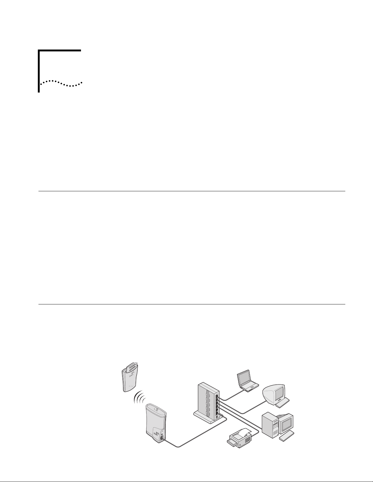
Operating in infrastructure mode and connected to an Ethernet hub, a single
workgroup bridge can combine up to four client devices—such as computers with
network adapters, printers, and 3Com NBX
workgroup . The workgroup associates with the wired network through a wireless
LAN access point such as the 3Com 11 Mbps Wireless LAN Access Point 6000.
Infrastructure configurations extend your wireless LAN to devices that would
otherwise have to be connected to the wired network.
Operating in
at close range without an access point, allowing their workgroups to
communicate. You may wish to set up an ad hoc network, for example, if a group
is working away from the office, or if a group in the office needs to share files
apart from the wired LAN.
The following examples illustrate ways you can use the wireless workgroup bridge
to configure Ethernet client devices into workgroups. (Details for setting up
specific configurations are in “Installing the Workgroup Bridge” on page 7.)
Y ou can connect several computers, including those with non-Windows operating
systems, and printers, as shown below.
ad hoc mode, two or more bridges can associate among themselves
®
telephone sets—into a multiclient
Page 6
HAPTER
C
NTRODUCTION
1: I
6
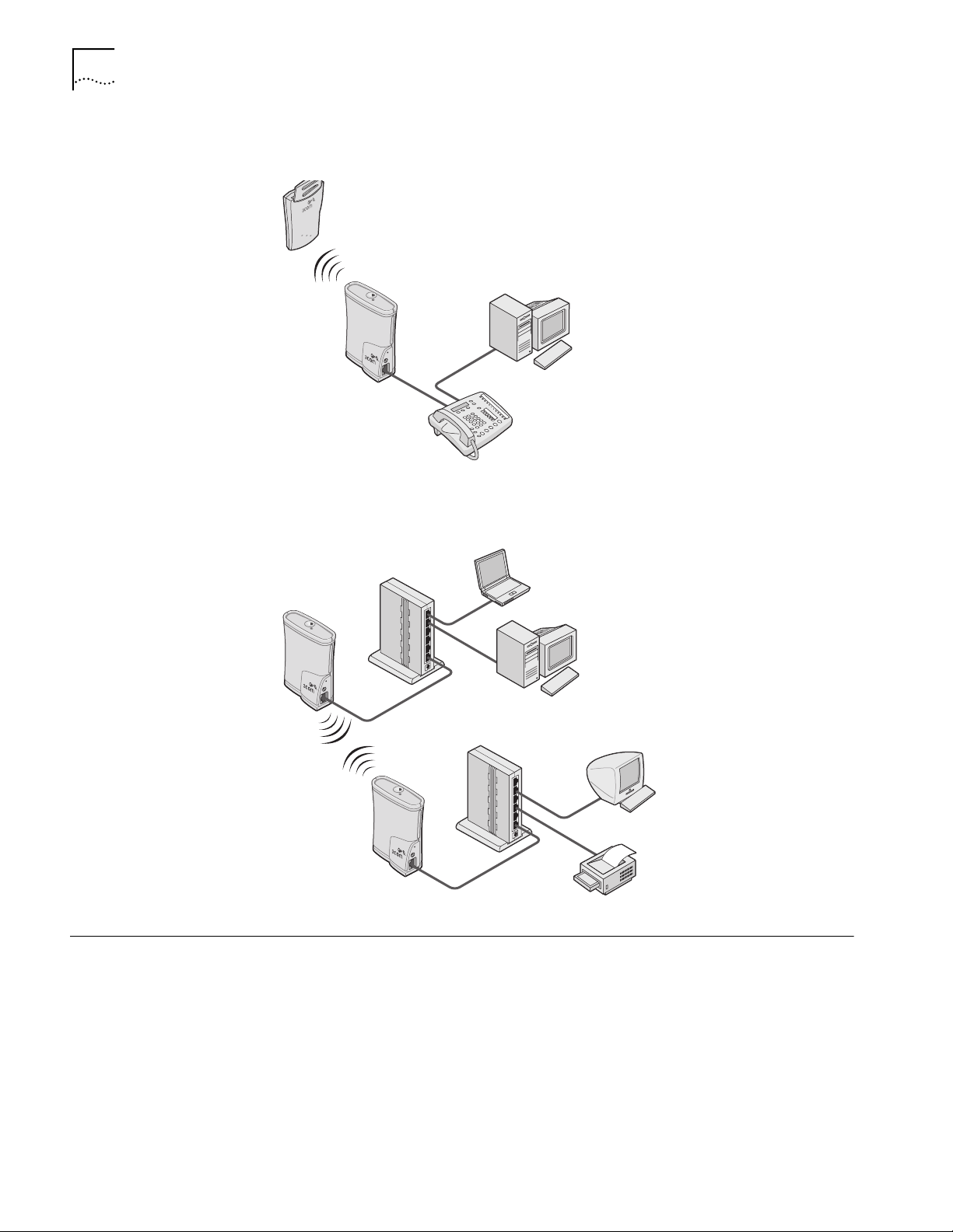
Converged Connections
in the Office
Workgroup Ad Hoc
Networks
Y ou can pr ovide converged voice and data services by connecting the bridge and a
computer to a 3Com NBX
®
telephone set as shown below.
Y ou can pr ovide flexible wireless network association for small gr oups in areas that
cannot be wired as shown below.
Product Registration and Support
To register your product with 3Com, go to the following Web page:
http://support.3com.com/registration/frontpg.pl
For support information, log on to the 3Com Web site at http://www .3com.com
and navigate to the product support page.
Page 7

2
Before You Begin
I
NSTALLING
Make sure that you have the following items, which are included with the
3Com 11 Mbps Wireless LAN Workgroup Bridge:
Power supply and power cord.
■
■
Standard Category 5 unshielded twisted pair (UTP) Ethernet cable.
To connect the bridge to a hub that does not have an uplink (MDIX) port, you
need an Ethernet crossover cable (not supplied).
Before you connect the bridge, decide where to place it and whether you need to
configure it.
To configure the bridge, you need a computer running one of the following
operating systems and one of the following browsers:
THE
W
ORKGROUP
B
RIDGE
Where should I Place the
Bridge?
Do I Need to Configure
the Bridge?
Operating Systems
Windows XP
Windows 2000 Internet Explorer 5.0 or later
Windows NT 4.0
Windows Me
Windows 98
Windows 95
You should place the bridge in a dry, clean location near the hub, telephone,
computer, or printer that will be connected to the bridge. The location must have
a power source and be within 300 feet (100 meters) of a Wi-Fi compliant wireless
LAN access point. The location should be away from transformers, heavy-duty
motors, fluorescent lights, microwave ovens, refrigerators, or other equipment
that could cause radio signal interference.
If your network has a DHCP server and no special security requirements, you can
use the workgroup bridge just as it is shipped from the factory. If your network is
more complex, you will want to organize devices so that you can manage the
wireless LAN easily and keep it secure. The following table shows the workgroup
bridge configuration factory defaults.
Property
Device Name
Device Location None
Browsers
Netscape 4.7 or later
Default Setting
3ComWWB
Page 8

HAPTER
C
2: I
NSTALLING
THE
ORKGROUP
W
B
RIDGE
8
Property
Help File Location Local Drive
Help File Path c:\Program Files\3Com\Management Help
IP Network Setting Obtain IP address automatically
IP Address Obtained automatically
Subnet Mask Obtained automatically
Gateway IP Address Obtained automatically
Clear Channel Select Off
Channel Uses access point channel.
Wireless LAN Service Area Attach to any WLAN Service Area automatically
Network Mode Access Point (infrastructure)
Access Point Privacy Mode Off
Network Traffic Accelerator Off (Wi-Fi interoperable)
Data Preamble Long (Wi-Fi interoperable)
Security Setting No Security (Open System)
Administration Password None
TFTP Server IP Address None (Uses TFTP port 69.)
Default Setting
If the configuration that was set at the factory does not meet your network
requirements, or if you want to customize settings, see “Summary of
Configuration Steps” on page 11 before connecting the bridge.
If the factory defaults meet your requirements, you can connect the bridge as
described in the following topics:
■
“Hub Connection” on page 9
“3Com NBX Telephone Set Connection” on page 9
■
■
“Computer Connection” on page 10
■
“Printer Connection” on page 10.
Connecting the Bridge
The workgroup bridge supports up to four specific Ethernet devices. It uses a
client list of MAC addresses to keep track of specific devices that have
been connected.
About the Client List Each time a new device is connected to the bridge, either directly or through a
hub, that device’s MAC address is added to the client list. After four different
devices have been connected, the client list is full, and you must refresh it before
the next new device can associate with the network through the bridge. To refr esh
Page 9
Connecting the Bridge 9
the list, you must access the bridge’s configuration management system. Details
on this procedure are in “Refreshing the Client List” on page 15.
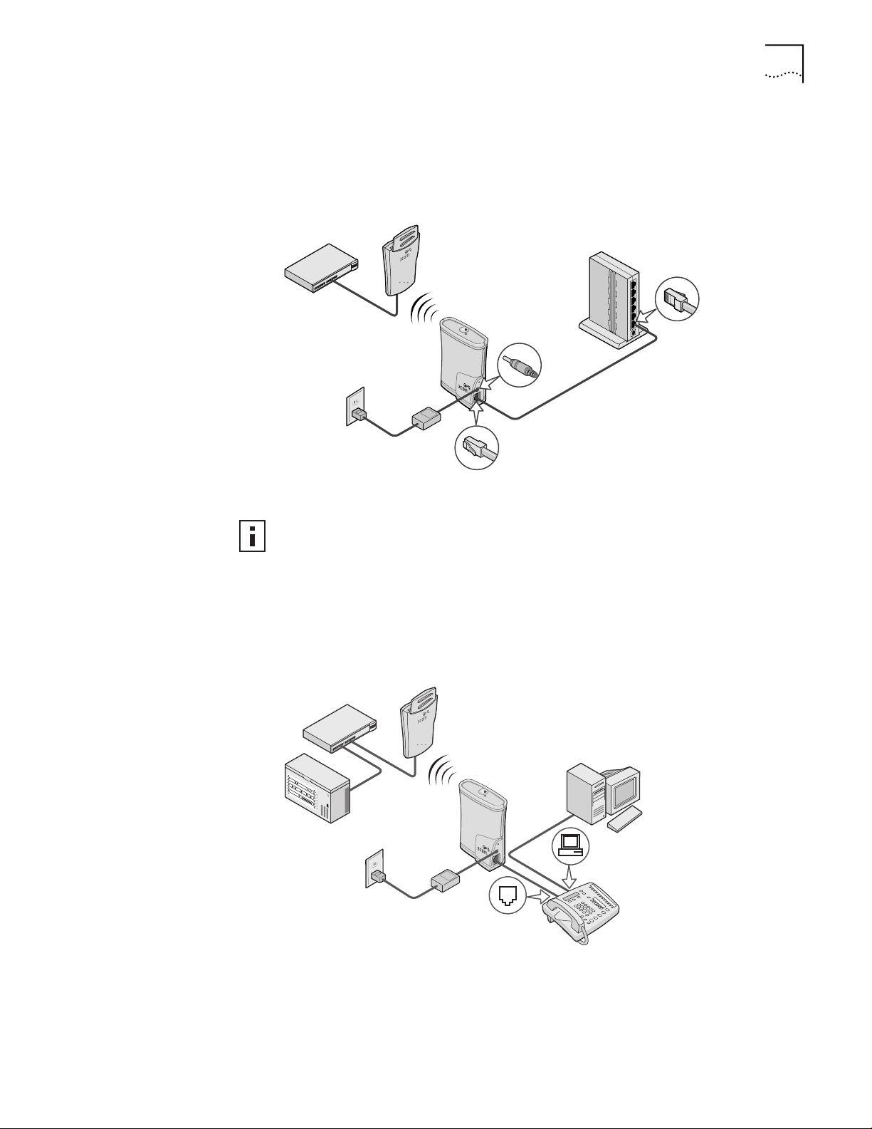
Hub Connection You can supply network connections for up to four devices, such as computers
and printers, by connecting the bridge to an Ethernet hub, as shown below.
Uplink port
3Com NBX
Telephone Set
Connection
Make sure that the workgroup bridge Ethernet cable is plugged into the hub
uplink (MDIX) port. If your hub does not have an uplink port, you must use an
Ethernet crossover cable (not provided), which can be connected in any port.
You can provide converged voice and data services in an office cubicle that is not
wired for Ethernet by connecting the bridge to a 3Com NBX telephone set as
shown below. The NBX server is connected to the same switch or router to which
the access point is connected.
Page 10

10
HAPTER
C
2: I
NSTALLING
THE
ORKGROUP
W
B
RIDGE
Printer Connection You can connect the bridge directly to a printer as shown below. Used this way,
the workgroup bridge allows you to place a printer in an area that is not wired
for Ethernet.
Computer Connection Y ou can connect the bridge dir ectly to a computer as shown below. Used this way,
the workgroup bridge can convert a desktop computer to a wireless computer.
This connection also allows you to configure a bridge before connecting it to
another device.
Checking the LED Indicators
When the bridge is connected to power, two LEDs indicate activity as described
below.
LED Indicator
Wireless
association
Ethernet
connection
Location Description
On the top of
the bridge
■
On—Unit is receiving power.
Off—Unit is not receiving power.
■
■
Blinking—The unit is transmitting or receiving. Faster
blinking indicates faster transmission speed.
At the RJ45
Ethernet
connector
■
On—Unit is receiving power.
Off—The unit is not receiving power.
■
■
Blinking—Wired LAN traffic is detected. Faster blinking
indicates heavier traffic.
Page 11

Summary of Configuration Steps 11
1
2
Summary of
Configuration Steps
Installing the Infrastructure Device Manager
The default configuration settings are shown in “Do I Need to Configure the
Bridge?” on page 7. To change these settings, follow these steps:
Install the 3Com Wireless Infrastructure Device Manager on a computer as
described in “Installing the Infrastructure Device Manager” on page 11.
The first time you configure the workgroup bridge, it is recommended that you
connect it directly to the computer where the device manager is installed.
Once the bridge has been configured to associate with the wireless network, you
can change its configuration at any time from any location on the network.
3 Launch the device manager and select the bridge as described in “Locating a
Wireless Device” on page 13.
4 Use the 3Com 11 Mbps Wireless LAN Workgroup Bridge Configuration
Management System to change and save the settings. For details, see
“Configuring Workgroup Bridges” on page 13.
5 After you save the configuration, disconnect the bridge from the computer and
connect it in its permanent place in the network.
For details on various ways to connect the bridge, see “Connecting the Bridge” on
page 8.
The 3Com installation CD contains the 3Com Wireless Infrastructure Device
Manager, a tool that helps you select 3Com wireless LAN devices and launch their
configuration management systems. The device manager must be installed on a
computer that has an Ethernet adapter and is running one of the Windows
operating systems and Web browsers listed in “Before You Begin” on page 7.
Follow these steps to install the device manager on your computer:
1 Turn on the computer.
2 Put the 3Com CD in the CD-ROM drive.
The setup menu appears. If it does not appear, you can start the setup menu from
the Windows Start menu. For example: Start/Run/D:setup.exe.
3 In the menu, click Install the Tools and Documentation.
4 In the next screen, click Install the Administration Tool.
5 Follow the instructions on the screens to complete the installation.
Optionally, you can install documentation before you reboot. You must r eboot the
computer before you can launch the tool.
6 To launch the tool from the Windows Start menu. Select Start/Programs/3Com
Wireless Infrastructure Device Manager/3Com Wireless Infrastructure
Device Manager
For details on using the tool, see “Locating a Wireless Device” on page 13.
Page 12

12 CHAPTER 2: INSTALLING THE WORKGROUP BRIDGE
Page 13

3
CONFIGURING WORKGROUP BRIDGES
If the workgroup bridge configuration that was set at the factory does not meet
your network requirements, or if you want to customize the settings, you can use
these tools to change the configuration:
3Com Wireless Infrastructure Device Manager—Helps you locate 3Com
wireless LAN devices on the network, select a device and view its properties,
and launch the device’s configuration management system. The device
manager must be installed on a computer that has an Ethernet adapter and is
running one of the Windows operating systems and Web browsers listed in
“Before You Begin” on page 7.
■ 3Com 11 Mbps Wireless LAN Workgroup Bridge Configuration
Management System—Resides on the 3Com workgroup bridge and lets you
configure that bridge through your Web browser.
Locating a Wireless Device
Make sure that the 3Com Wireless Infrastructure Device Manager is installed. The
device to be configured must be either connected directly to the computer or
associating with the wireless network, and it must connected to power. If you
have more than one device connected, make a note of the MAC address of the
device you want to select so that you can identify it in the device manager.
1 To launch the device manager, select Start/Programs/3Com Wireless Infrastructure
Device Manager/3Com Wireless Infrastructure Device Manager.
If you have more than one network adapter installed on your computer, you may
be prompted to choose a network adapter. Choose the appropriate adapter and
click OK.
The Wireless Network Tree appears in the 3Com Wireless Infrastructure Device
Manager window. The tree lists all WLAN service areas on the network and
expands to show the 3Com wireless LAN devices that are associated to each
service area. Devices in a different subnet than your computer are identified with
exclamation points (!). You can refresh this display by clicking Refresh. You should
refresh the display, for example, after you change a device IP address.
2 In the Wireless Network Tree, select the device you want to configure.
If more than one wireless LAN device appears in the tree and you ar e not sure that
you have selected the right one, click Properties and check the MAC address to
verify that it is the one you want.
3 Click Configure.
If the selected device is on the same subnet as your computer, the Configuration
Management System main page appears in your Web browser.
If the selected device is on a different subnet, the device manager helps you to
assign an IP address on the same subnet as your computer. You may accept the
address offered or enter an address and click Next. The next window prompts for
Page 14

14 CHAPTER 3: CONFIGURING WORKGROUP BRIDGES
an administrative password to allow the new IP address to be set. If this is the first
time the device is being configured, leave the password field blank and click Next.
The Configuration Management System main page appears in your Web browser.
The following table describes the functions of the buttons in the 3Com Wireless
Infrastructure Device Manager window.
Button Description
Properties Displays the following properties of the selected device: Device Name, Device
Configure Launches the Configuration Management System for the selected device. If
Refresh Scans the network and displays the connected 3Com 11 Mbps Wireless
Choose NIC If your computer has more than one network interface card installed, allows
Close Closes the device manager window and ends the session.
Help Launches the device manager help page in your browser.
Type, ESSID, IP Address, Subnet Mask, and MAC Address.
the selected device is on a different subnet, you are prompted to assign an
address on the same subnet as your computer.
LAN devices.
you to choose which card you want to use.
Entering, Clearing,
and Applying System
Configuration
Settings
Changing System Properties
Some pages in the configuration have three buttons: Enter, Clear all Changes, and
Apply all Changes. Here is how to use these buttons:
■ Enter stores settings temporarily in the device cache memory, but does not
apply them permanently in the device nonvolatile memory. You can use Enter
to save changes while you are configuring, but you cannot see the changes on
the System Summary Page until after you click Apply all Changes. You can use
Enter when you are making changes on multiple configuration pages, but you
do not want the changes to take effect until after all have been set.
■ Clear all Changes returns the settings in the device cache memory to the values
they had before you last clicked Apply all Changes.
■ Apply all Changes stores the settings permanently in the device nonvolatile
memory . After you click Apply all Changes, the new configuration settings take
effect and you can see the changes on the System Summary page.
If you forget to Enter or Apply all Changes before moving to a new configuration
page, your changes to the current page are lost. If you forget to Apply all
Changes before closing the browser, your changes are lost.
Under System Configuration, click System Properties. The System Properties page
displays the properties of the selected device. You can change properties by
entering values in the fields and clicking the radio buttons (see the following
table). When you are finished, click
Enter or Apply all Changes.
The following table describes the properties.
Property Description Default Value
Device Name This name appears in the System Summary
window. You can change the default name to
one of your choice.
3ComWWB
Page 15

Setting IP Network Properties 15
Property Description Default Value
Device Location Optionally, you can enter the location of the
device.
Help File Location ■ Web Server: Help files are located on the
network at the specified Help File Path.
■ Local Drive: Help files are located on the
client at the specified Help File Path.
Help File Path The location of the Configuration
Management System help files on the web
server or on the local drive.
If you want to have access to help when you
click the ? in the configuration pages, you must
install the help from the 3Com CD in the
default location on the local computer. If you
install the help in a different location on the
local disk or on a web server, you must set the
Help File Path to the correct location.
None
Local Drive
c:\Program Files\3Com\
Management Help
Setting IP Network Properties
Under System Configuration, click IP Network. The IP Network Properties page
appears, where you can change the settings shown in the table below.
If you change the IP address and click Apply all Changes, you cannot continue to
configure the device using the old IP address. Therefore, you should click Enter if
want to continue configuring this device after you make this change. Otherwise,
you must do the following:
1 Close your browser.
2 Return to the 3Com Wireless Infrastructure Device Manager and click Refresh.
3 Select the device and click Configure to start a new configuration session.
Setting Description
IP Network Setting This setting allows you to change the IP address of the device.
To let the device get an IP address automatically from a DHCP server,
click Obtain an IP address automatically and click Enter.
To specify an IP address, click Specify an IP address, enter the IP address
parameters in the spaces provided, and click Enter.
IP Address
Subnet Mask
Gateway IP Address
Parameters for use when you click Specify an IP address. Enter the
parameters in the spaces provided, and click Enter.
Refreshing the Client List
The workgroup bridge supports up to four specific clients (for example, computers
and printers) and keeps track of the clients with a list of their MAC addresses.
After the client limit is reached, you must refresh the client list to allow a new
client to associate with the network. For example, in a hub configuration with four
clients connected, if you disconnect a desktop computer and connect a new
laptop in its place, you must refresh the client list to establish network association
for the laptop. Follow these steps:
1 Disconnect a client by unplugging its Ethernet cable from the hub or the bridge.
2 Use the 3Com Wireless Infrastructure Device Manager to select the workgroup
bridge and launch its configuration management system.
Page 16

16 CHAPTER 3: CONFIGURING WORKGROUP BRIDGES
3 Under System Configuration, click IP Network. The IP Network Properties page
appears. Click Refresh Client List.
4 Connect the new client by plugging its Ethernet cable into the hub or the bridge.
Setting Wireless Network Properties
Under System Configuration, click Wireless Network Properties. The Wireless
Network Properties page appears, where you can select radio channel settings and
advanced performance settings. When you are finished, click
Enter or Apply all
Changes.
■ Network Mode—Click Access Point (Infrastructure) to associate with an
access point. Click Ad-hoc (Peer-to-Peer) to associate in ad hoc mode.
■ Wireless LAN Service Area—Click Attach to any WLAN Service Area (ESSID)
automatically to allow the bridge to associate with any access point that is also
set to use any ESSID. In this mode, the bridge detects access points set for any
ESSID and uses the ESSID of the access point with the best signal strength. This
mode is not available when the network mode is Ad-hoc (Peer-to-Peer).
Click Specify the Wireless LAN Service Area and type the WLAN service area
name to allow the bridge to associate only with access points with the same
service area. You must specify the WLAN service area when the network mode
is Ad-hoc (Peer-to-Peer).
To maintain wireless association, the WLAN service area on a bridge and the
access point with which it is associated must match exactly. Therefore, if you
change the access point WLAN service area, make sure to change the bridge
WLAN service area also.
■ Clear Channel Select—When the network mode is Access Point
(Infrastructure), this option is enabled automatically and cannot be changed.
When this option is enabled, the device scans the primary channels to
determine the traffic on those channels and chooses the channel with the least
number of packets.
Setting Advanced Performance Properties
To allow the device to find a channel automatically, click On (automatically
select the best channel).
To select a specific channel, click Off (specify the channel) and choose a
channel from the Channel list. This option can be used only when the network
mode is Ad-hoc (Peer-to-Peer).
■ Access Point Privacy Mode—This mode only applies when the network
mode is Access Point (Infrastructure) and should only be used when access
points are set with privacy enabled. Click On to associate with access points set
with privacy mode enabled. Click Off to associate with access points set with
privacy mode disabled. When privacy mode is on, you must specify a Wireless
LAN Service Area, which must match the access point service area exactly.
When the network mode is Access Point (Infrastructure) the advanced
performance properties are set automatically to match the access point. When the
mode is Ad-Hoc (Peer-to-Peer) you may specify these properties.
Under System Configuration, click Wireless Network Properties. On the Wireless
Network Properties page, click the link to go to advanced wireless network
configuration. The Advanced Wireless Network page appears, where you can
Page 17

Setting up an Ad Hoc Network 17
change the settings shown below. When you are finished, click Enter or Apply all
Changes.
■ Network Traffic Accelerator—To increase performance, click On (Enhanced
performance). If you experience problems when equipment other than 3Com
11 Mbps Wireless LAN equipment is being used, click Off (Wi-Fi Interoperable).
■ Data Preamble—To increase performance, click Short (Enhanced
performance). When equipment that does not support short preamble is also
being used, click Long (Wi-Fi Interoperable).
Setting up an Ad Hoc Network
Operating in ad hoc mode, two or more bridges can associate among themselves
at close range without an access point, allowing their workgroups to
communicate. You may wish to set up an ad hoc network, for example, if a group
is working away from the office, or if a group in the office needs to share files
apart from the wired LAN.
Follow these steps to set up an ad hoc network with two workgroup bridges.
To ensure correct operation, the settings on the two bridges must match exactly.
1 Use the 3Com Wireless Infrastructure Device Manager to select the first
workgroup bridge and launch its configuration management system.
2 Under System Configuration, click Wireless Network.
3 In the Wireless Network page:
a Locate the Network Mode field and click Ad-hoc (Peer-to-Peer).
b The Wireless LAN Service Area defaults to Any ESSID and Clear Channel Select
defaults to On (automatically select the best channel. Optionally, you can
specify the Wireless LAN Service Area and the Channel as described in “Setting
Wireless Network Properties” on page 16.
c Click
Enter or Apply all Changes.
d Click To go to advanced wireless network configuration.
4 In the Advanced Wireless Network page:
a Set the Data Preamble.
To increase performance, click Short (Enhanced performance). When
equipment that does not support short preamble is also being used, click Long
(Wi-Fi Interoperable).
b Click
Enter or Apply all Changes.
5 Security settings default to No Security (Open System). Optionally, you can set
40-bit Shared Keys security as described in “40-bit Shared Key (Wi-Fi)” on
page 18. (You cannot use 128-bit security options in ad hoc mode.)
6 When you are finished, click Apply all Changes.
7 End the browser session.
8 Repeat the procedure with the second workgroup bridge. Make sure you
configure bridge settings to match exactly. When you are finished, click Apply all
Changes and end the browser session.
Page 18

18 CHAPTER 3: CONFIGURING WORKGROUP BRIDGES
9 Connect the Ethernet devices to the bridges. If you use hubs, make sure that the
workgroup bridges are connected through the hub uplink ports.
Changing Security Settings
Under System Configuration, click Security Settings. The Security Settings page
appears, where you can select the type of security to be used on the bridge. The
bridge can be configured to support one type of security at a time. You can
change the settings by clicking the radio buttons and entering values in the fields.
When you are finished, click
Enter or Apply all Changes.
The following sections describe the settings. To maintain wireless association, the
settings on clients and the access points they associate with (or other members of
an ad hoc network) must match exactly.
If you are configuring through a wireless association (not on the wired LAN) and
you reconfigure both the WLAN service area and the security settings, be sure to
click Enter to save changes temporarily until you are finished. Then click Apply all
Changes. If you apply one set of changes and not the other, the bridge may lose
association with one access point before it is configured to associate with another.
No Security (Open
System)
No encryption is used. The network communications could be intercepted by
unintended recipients.
40-bit Shared Key (Wi-Fi) This option encrypts the wireless transmissions to protect data, but still allows
communication among compatible wireless LAN clients and access points from
third-party manufacturers that are Wi-Fi certified.
This type of security requires you to set up encryption in one of the following
ways:
■ String—For use only with other 3Com 11 Mbps wireless LAN devices, an
encryption string is a case-sensitive string of characters between 6 and 30
characters long. To enter the string, click Enter a string to generate shared keys.
Then type any combination of letters and numbers in the space provided and
click
Enter or Apply all Changes.
■ Shared keys—Hexadecimal keys are sequences of hexadecimal digits arranged
into four keys. A hexadecimal digit may be a letter from A to F or a number
from 0 to 9. This type of encryption is compatible with equipment from other
manufacturers that use Wi-Fi certified 40-bit encryption. T o enter the keys, click
Specify shared keys and which to use. Then click To specify and select the
shared keys. In the shared keys window, enter all the keys in the provided
spaces, then click a radio button in the Selected Key column to specify which
key to use and click
Enter or Apply all Changes.
128-bit Shared Key This option can be used with other 3Com 11 Mbps Wireless LAN devices and with
equipment from certain manufacturers that also support 128-bit shared key
encryption. It provides a higher level of security than the 40-bit Shared Key (Wi-Fi)
option and uses a more complicated type of encryption. This type of security
requires you to set up encryption using a string or shared keys as described in
“40-bit Shared Key (Wi-Fi)” on page 18.
Page 19

Resetting the Bridge 19
128-bit Dynamic Security
Link
Setting up the Wireless
Network Login
This option can only be used with other 3Com 11 Mbps Wireless LAN devices. It is
the highest level of security, requiring a user name and password to access the
wireless LAN. The user name and password set up on the bridge must match those
set up on the access point. Each network session creates a unique, one-time
encryption code.
If you choose this type of security, you must also set up a login as described in
“Setting up the Wireless Network Login”.
If you configure a bridge for 128-bit Dynamic Security Link, you must also set up a
login user name and password, which must match a listing in the access point
access control list.
In the Security Settings page, click 128-bit Dynamic Security Link. Then click the
link to modify the wireless network login. In the Wireless Network Login page,
enter a login name and password, and confirm the password in the spaces
provided. When you are finished, click Save.
Resetting the Bridge If the bridge stops responding correctly, you can perform a reset, which disrupts
the network association temporarily, but does not affect the bridge configuration
settings. To reset the bridge, under Tools, click Reset Wireless Workgroup Bridge.
In the next page, click Reset.
Restoring a Bridge to Factory Defaults
You can restore bridge settings to the defaults that were set at the factory
as follows:
1 Under Tools, click Restore Factory Defaults.
2 Click Restore.
You can also restore the bridge factory settings by inserting a pointed object (such
as the end of a paper clip that you have unbent) into the reset hole on the front
near the RJ-45 connector and holding for five seconds.
If the bridge was using an IP address setting other than the default, restoring the
factory defaults will change the IP address. If you want to continue configuring the
bridge, do the following:
1 Close your browser.
2 Return to the 3Com Wireless Infrastructure Device Manager and click Refresh.
3 Select the device and click Configure to start a new configuration session.
Upgrading the System You can download firmware updates or updates of the configuration
management system from the 3Com Web site and install those updates on
the bridge.
The upgrade uses the 3Com customer support Trivial File Transfer Protocol (TFTP)
server. The workgroup bridge acts as a TFTP client to receive the download.
To avoid problems that could occur if a wireless association were interrupted
during the upgrade, it is recommended that you perform the upgrade from a
Page 20

20 CHAPTER 3: CONFIGURING WORKGROUP BRIDGES
computer that is wired to the LAN and has access to the device you want to
upgrade.
If you upgrade both the firmware and the configuration management system,
be sure to upgrade the Web server file system first.
Locating Upgrade Files To locate upgrade files:
1 Log on to the 3Com Web site at http://www.3com.com.
2 Navigate to the product support page.
3 Navigate to the software download page and locate the files you want
to download.
4 Read the instructions on the download page, and make a note of the file names
and the IP address of the 3Com TFTP server.
Installing an Upgrade After you obtain the upgrade file names and TFTP server IP address, perform the
following steps on a computer that is wired to the network and has access to the
device you want to upgrade:
Changing the Administration Password
1 Use the 3Com Wireless Infrastructure Device Manager to select the device and
launch its configuration management system.
2 Under Tools, click Upgrade System.
3 Select the item to upgrade:
To upgrade the configuration management system, click Configuration
Management System.
To upgrade firmware, click Wireless Workgroup Bridge Firmware.
4 Verify that the file name displayed is the same as the name you got from the
3Com Web site. If it is not the same, delete it and enter the name you got from
the Web site.
5 Enter the IP address of the 3Com TFTP server.
6 Click Upgrade.
The first time you launch the Configuration Management System on the device or
after you reset a device to factory defaults, you are prompted to set an
administrative password. Although a password is not required, 3Com
recommends that you set a password to protect against unauthorized access.
After you set the password, you must enter a user name and password each time
you launch the configuration for the device.
Backing up a
Configuration
Under Tools, click Change Administration Password. The Change Administration
Password page appears, where you can change the administration password for
the device. Enter the current password and new password in the spaces provided
and click Save.
As part of system maintenance, you should save and back up the configurations of
individual bridges in case you need to reload them in the future. The backup saves
Page 21

Restoring a Configuration 21
all the parameters of the selected bridge in a file on your computer . The file can be
used later to restore the configuration on this or another bridge.
1 Set the bridge parameters in the System Configuration pages.
2 Under Tools, click Backup Wireless Workgroup Bridge.
3 In the next page, click Backup Now.
4 Specify a name and location for the backup, and click OK.
Restoring a
Configuration
Viewing System Status
If you have stored a backup configuration on your computer, you can restore the
configuration as follows:
1 Under Tools, click Restore Wireless Workgroup Bridge.
2 In the next page, click Browse and select the backup file to upload to the access
point.
3 Click Restore.
The configuration is restored and activated on the bridge. This operation may
cause the bridge to reboot.
If the bridge was using an IP address setting other than the backup, restoring the
configuration will change the IP address. If you want to continue configuring the
bridge, do the following:
1 Close your browser.
2 Return to the 3Com Wireless Infrastructure Device Manager and click Refresh.
3 Select the device and click Configure to start a new configuration session.
Under System Status, you can view the following information:
■ Click Connection Status to see the data rate and signal strength at which the
bridge is associating with the access point. Signal strength values range from
0 (no signal) to 5 (excellent signal quality).
Interoperating with Third-Party Equipment
■ Click System Summary to see information about the bridge.
■ Click Refresh to update the information.
Because 3Com 11 Mbps Wireless LAN equipment complies with IEEE 802.11
standards, it can interoperate with third-party equipment that also complies with
the standards. However, some third party equipment may not support 3Com
enhanced performance features. You may need to turn off the Network Traffic
Accelerator and Data Preamble transmission properties to support this equipment
on the network.
Page 22

22 CHAPTER 3: CONFIGURING WORKGROUP BRIDGES
Page 23

4
TROUBLESHOOTING
If you have difficulty with the 3Com 11 Mbps Wireless LAN Workgroup Bridge, try
the solutions in the following table.
Symptom Solutions
Four devices have been
connected to the bridge, either
simultaneously or sequentially.
After connecting another
device, the new device cannot
associate with the network.
After you change the IP
address, after you restore a
backup configuration, or after
you reset the bridge to factory
defaults, the Configuration
Management System stops
responding and you cannot
continue configuring the
bridge.
The bridge cannot associate
with an access point.
The Wireless Network Tree
does not appear in the 3Com
Wireless Infrastructure Device
Manager window.
The workgroup bridge supports up to four specific clients (for
example, computers and printers) and keeps track of them
using a client list of MAC addresses. After the client limit is
reached, you must refresh the client list to allow a new client
to associate. For example, in a hub configuration with four
clients connected, if you disconnect a desktop computer and
connect a laptop in its place, you must refresh the client list
to establish network association.
1 Disconnect a client by unplugging its Ethernet cable from
the hub.
2 Use the 3Com Wireless Infrastructure Device Manager to
select the workgroup bridge and launch its configuration
management system.
3 Under System Configuration, click IP Network. The IP
Network Properties page appears. Click Refresh Client List.
4 Connect the new client by plugging its Ethernet cable into
the hub.
If you change the IP address and click Apply all Changes, you
cannot continue to configure the device using the old IP
address. Therefore, you should click Enter if want to continue
configuring this device after you make this change. Similarly,
after you restore a backup configuration or reset the bridge
to factory defaults, the IP address setting may be changed.
To recover from this situation and continue configuring the
bridge:
1 Close your browser.
2 Return to the 3Com Wireless Infrastructure Device
Manager and click Refresh.
3 Select the device and click Configure to start a new
configuration session.
■ Make sure the security settings on the bridge match those
on the access point.
■ Check the privacy mode set on the access point and make
sure the bridge setting matches. Launch the bridge
configuration management system. Under System
Configuration, click Wireless Network. Click Access Point
Privacy Mode On or Off.
Verify that you are using the correct network adapter. In the
device manager window, click Choose NIC. Select the
network adapter for the network you want to scan, and click
OK.
Page 24

24 CHAPTER 4: TROUBLESHOOTING
Disconnecting the Bridge
Symptom Solutions
Two workgroup bridges cannot
communicate in ad hoc mode.
128-bit security settings do not
work in ad hoc mode.
You are running Windows 95
or Windows NT. After you
connect the workgroup bridge,
your computer cannot obtain a
valid IP address.
To ensure correct operation in ad hoc mode, the settings on
the two bridges must match exactly. Make sure that the
Wireless LAN Service Area, channel selections, Data Preamble
setting, and security setting are the same on both bridges.
128-bit security settings are not supported in ad hoc mode.
Use 40-bit Shared Keys setting instead.
The workgroup bridge configuration settings may not be
compatible with the network. If they are not, and your
Windows 95 or Windows NT computer is set up to obtain its
IP address from a DHCP server, the workgroup bridge is
unable to associate with the network to obtain the IP
address. To work around this problem, set a static IP address
on your computer. Then set the workgroup bridge
configuration to match the network. When the bridge is able
to associate, reset your computer to obtain its IP address from
the DHCP server.
CAUTION: Disconnecting the bridge ends the network association. To avoid
possible data loss, exit all networking applications on connected devices before
you disconnect the bridge.
Uninstalling the Infrastructure Device Manager
Uninstalling
Configuration Help
Files
Upgrading Bridge Firmware
1 Unplug the workgroup bridge Ethernet cable from the hub or other device.
2 Unplug the workgroup bridge power cord.
Use the standard operating system procedure for r emoving programs. Under most
Windows operating systems, from the Start menu select Settings and then select
Control Panel. In the Control Panel, double click Add/Remove Programs and follow
the prompts to remove the program.
???what is the procedure? do we need a procedure??
Firmware is the software that is installed on the bridge at the factory. Some problems
can be solved by installing a new version of the firmware (upgrading firmware).
For details on how download a firmware update from the 3Com customer support
Web site and install it on your bridge, see “Upgrading the System” on page 19.
Page 25

INDEX
Numbers
128-bit Dynamic Security Link 19
128-bit Shared Key 18
40-bit Shared Key (Wi-Fi) security 18
A
access point
IP address
changing 15
refreshing after changing 13
LEDs 10
viewing the wireless network
tree
access point privacy mode 16
ad hoc network 5, 17
adapter, choosing 14
administration password, changing 20
B
backing up configurations 20
bridge
changing properties
configuring 13
maintaining configurations 20
password 20
restoring factory defaults 19
user name 20
C
changing passwords
administration
choosing a NIC 14
client list 8
client list, refreshing 15, 23
configuration
maintenance for bridges
Configuration Management System 13
D
Dynamic Security Link 19
E
encryption
settings
string 18
15
13
14
20
20
18
G
guidelines, security 18
H
hexadecimal keys 18
I
infrastructure 5
installation
bridge
firmware
interoperating with third-party
equipment
IP address 8, 13
specifying 15
7
bridge
19, 24
21
K
keys 18
L
LED
access point
10
N
network 5
ad hoc 5, 17
traffic settings 16, 17
Network Mode 16, 17
NIC, choosing 14
No Security 18
O
open system 18
P
password 20
changing administrator 20
performance settings 16, 17
Privacy Mode 16
product registration 6
S
security
128-bit Dynamic Security Link
128-bit Shared Key 18
40-bit Shared Key (Wi-Fi) 18
guidelines 18
no security 18
security settings 18
settings
radio channel
shared keys 18
16, 17
T
third-party interoperability 21
troubleshooting 23
bridge 24
bridge firmware 19
U
upgrading
bridge firmware
user name, on bridge management
tool
20
19, 24
W
warranty, registration 6
wireless 5
network tree 13
Wireless Network Properties 16, 17
19
F
firmware upgrade 19, 24
bridge 19, 24
R
refreshing the client list 8, 15, 23
registration 6
restoring settings to factory defaults 19
Page 26

Page 27

REGULATORY COMPLIANCE INFORMATION
FCC RADIO-FREQUENCY
E
XPOSURE NOTICE
FCC PART 15 NOTICE
(A
PPLICABLE TO USE WITHIN
THE USA)
MANUFACTURER’S
D
ECLARATION OF
C
ONFORMITY
This device generates and radiates radio-frequency energy. In order to comply with FCC radio-frequency radiation exposure
guidelines for an uncontrolled environment, this equipment has to be installed and operated while maintaining a minimum
body to antenna distance of 20 cm.
This product does not contain any user serviceable components. Any unauthorized product changes or modifications will
invalidate 3Com’s warranty and all applicable regulatory certifications and approvals.
This device complies with part 15 of the FCC Rules. Operation is subject to the following two conditions: (1) This device may
not cause harmful interference, and (2) this device must accept any interference received, including interference that may cause
undesired operation.
WARNING: This equipment has been tested and found to comply with the limits for a Class B digital device, pursuant to Part
15 of the FCC Rules. These limits are designed to provide reasonable protection against harmful interference in a residential
installation. This equipment generates, uses and can radiate radio frequency energy and, if not installed and used in accordance
with the instructions, may cause harmful interference to radio communications. However, there is no guarantee that
interference will not occur in a particular installation. If this equipment does cause harmful interference to radio or television
reception, which can be determined by turning the equipment off and on, the user is encouraged to try to correct the
interference by one or more of the following measures:
■ Reorient or relocate the receiving antenna.
■ Increase the separation between the equipment and receiver.
■ Connect the equipment into an outlet on a circuit different from the one which the receiver is connected to.
■ Consult the dealer or an experienced radio/TV technician for help.
The user may find the following booklet prepared by the Federal Communications Commission helpful:
The Interference Handbook
This booklet is available from the U.S. Government Printing Office, Washington, D.C. 20402. Stock No. 004-000-00345-4.
3Com Corporation
5400 Bayfront Plaza
P.O. Box 58145
Santa Clara, CA 95054-8145
(408) 326-5000
Declares that the product:
Date: 25 October 2001
Brand Name: 3Com Corporation
Model Number: WL-308
Equipment Type: Wireless LAN Workgroup Bridge
Complies with Part 15 of the FCC rules. Operation is subject to the following two conditions: (1) this device may not cause
harmful interference, and (2) this device must accept any interference received, including interference that may cause
undesired operation.
INDUSTRY CANADA NOTICE
(A
PPLICABLE TO USE WITHIN
C
ANADA)
AVIS DE CONFORMITÉ À LA
R
ÉGLEMENTATION
D’INDUSTRIE CANADA
3Com Corporation WL-308
Tested to Comply
With FCC Standards
FOR HOME OR OFFICE USE
This Class B digital apparatus complies with Canadian ICES-003.
To prevent radio interference to the licensed service, this device is intended to be operated indoors and away from windows to
provide maximum shielding. Equipment (or its transmit antenna) that is installed outdoors is subject to licensing.
Cet appareil numérique de la classe B est conform à la norme NMB-003 du Canada.
Pour empêcher que cet appareil cause du brouillage au service faisant l'objet d'une licence, cet appareil doit être utilisé à
l'intérieur seulement et devrait être placé loin des fenêtres afin de fournir un écran de blindage maximal.
Page 28

EUROPEAN COMMUNITY - CE
N
OTICE
Marking by the symbol:
indicates compliance of this equipment to the R&TTE Directive 1999/5/EC. Such marking is indicative that this equipment meets
or exceeds the following technical standards:
■ EN 300 328-2 - Electromagnetic compatibility and Radio spectrum Matters (ERM); Wideband Transmission systems; data
transmission equipment operating in the 2,4 GHz ISM band and using spread spectrum modulation techniques
■ ETS 300 826 - Electromagnetic compatibility and Radio spectrum Matters (ERM); ElectroMagnetic Compatibility (EMC)
standard for 2,4 GHz wideband transmission systems and HIgh PErformance Radio Local Area Network (HIPERLAN)
equipment
■ EN 60950 - Safety of information technology equipment, including electrical business equipment.
SAFETY COMPLIANCE NOTICE This device has been tested and certified according to the following safety standards and is intended for use only in Information
Technology Equipment which has been tested and certified to these or other equivalent standards:
■ UL Standard 1950 / CSA C22.2 No. 950
■ IEC 60950
■ EN 60950
Published December, 2001
User Guide Version 1.0.3
 Loading...