

Page 1

11 Mbps Wireless LAN
Access Point 8000
User Guide
Version 1.1
http://www.3com.com/
http://support.3com.com/registration/frontpg.pl/
Published April, 2002
Version 1.1.2
Page 2

3Com Corporation
5400 Bayfront Plaza
Santa Clara, California
95052-8145
Copyright © 2002 3Com Corporation. All rights reserved. No part of this documentation may be
reproduced in any form or by any means or used to make any derivative work (such as translation,
transformation, or adaptation) without written permission from 3Com Corporation.
3Com Corporation reserves the right to revise this documentation and to make changes in content from time
to time without obligation on the part of 3Com Corporation to provide notification of such revision or change.
3Com Corporation provides this documentation without warranty, term, or condition of any kind, either
implied or expressed, including, but not limited to, the implied warranties, terms or conditions of
merchantability, satisfactory quality, and fitness for a particular purpose. 3Com may make improvements or
changes in the product(s) and/or the program(s) described in this documentation at any time.
If there is any software on removable media described in this documentation, it is furnished under a license
agreement included with the product as a separate document, in the hard copy documentation, or on the
removable media in a directory file named LICENSE.TXT or !LICENSE.TXT. If you are unable to locate a copy,
please contact 3Com and a copy will be provided to you.
UNITED STATES GOVERNMENT LEGEND
If you are a United States government agency, then this documentation and the software described herein
are provided to you subject to the following:
All technical data and computer software are commercial in nature and developed solely at private expense.
Software is delivered as “Commercial Computer Software” as defined in DFARS 252.227-7014 (June 1995)
or as a “commercial item” as defined in FAR 2.101(a) and as such is provided with only such rights as are
provided in 3Com’s standard commercial license for the Software. Technical data is provided with limited
rights only as provided in DFAR 252.227-7015 (Nov 1995) or FAR 52.227-14 (June 1987), whichever is
applicable. Y ou agree not to remove or deface any portion of any legend provided on any licensed program
or documentation contained in, or delivered to you in conjunction with, this User Guide.
Unless otherwise indicated, 3Com registered trademarks are register ed in the United States and may or may
not be registered in other countries.
3Com and the 3Com logo are registered trademarks and AirConnect is a trademark of 3Com Corporation.
Wi-Fi is a trademark of the Wireless Ethernet Compatibility Alliance.
All other company and product names may be trademarks of the respective companies with which they
are associated.
EXPORT RESTRICTIONS: This product contains Encryption and may require US and/or Local Government
authorization prior to export or import to another country.
Page 3

C
ONTENTS
1
NTRODUCTION
I
Wireless and Wired Networks 1
Access Point 8000 Feature Summary 1
Installation Overview 2
NSTALLING
I
2
Before You Begin 5
Deciding Where to Place Equipment 5
Connecting the Standard Antenna 6
Placing the Access Point 6
Mounting on a Wall 7
Mounting on a Ceiling 8
Connecting Power 9
Connecting to an Ethernet Network 10
Checking the LEDs 10
Selecting A Different Antenna 11
Omnidirectional Antenna 11
Ceiling Mount Omnidirectional Antenna 12
Ceiling Mount Hallway Antenna 12
Directional Panel Antenna 13
Connecting an Optional Antenna 13
Installing Software Utilities 14
3
CCESS
A
Upper-Layer Authentication 17
EAP-MD5 17
EAP-TLS 17
3Com Serial Authentication 18
Additional Security Configuration Options 18
802.1x RADIUS Support 19
Using the Wireless 802.1x Agent 19
Authentication and Login 19
802.1x Client Properties 20
P
THE
OINT
CCESS
A
ECURITY
S
P
OINT
C
4
ONFIGURING
Installing the Device Manager 23
Launching a Wireless Device Configuration 24
THE
A
CCESS
P
OINT
8000
Page 4

Using the Configuration Management System 25
Changing Access Point Properties 26
Setting Network Properties 26
Setting Data Transmission Properties 27
Setting Advanced Data Transmission Properties 28
Setting up Security 29
Security Settings 29
Access Point Encryption Settings 30
Setting up a User Access List 30
Setting up a MAC Address Access List 31
Defining RADIUS Servers 31
Configuring for SNMP Management 31
Defining a TFTP Server 32
Setting up a System Log 32
Upgrading the System 32
Changing the Administration Password 33
Restoring Factory Defaults 33
Resetting the Access Point 33
Backing up Configurations 33
Restoring Configurations 33
Viewing Statistics 34
Viewing System Status 35
ONDUCTING
C
5
Before You Begin 37
Choosing Trial Locations 37
Environmental Requirements 37
Electrical Requirements 38
Summary of the Survey Procedure 38
Using the Site Survey Tool 39
Setting up Equipment 39
Launching the Tool 39
Configuring the Survey 39
Running the Tests 39
Interpreting Test Results 40
Site Survey Menus 41
6
ROUBLESHOOTING
T
T
A
ECHNICAL
Online Technical Services 45
World Wide Web Site 45
3Com Knowledgebase Web Services 45
3Com FTP Site 45
Support from Your Network Supplier 46
Support from 3Com 46
A
S
UPPORT
S
ITE
URVEY
S
Page 5

Returning Products for Repair 48
EGULATORY
R
NDEX
I
OMPLIANCE
C
NFORMATION
I
Page 6

Page 7

1
I
NTRODUCTION
The 3Com wireless product family lets you set up a local area network (LAN)
without the restraints of network cabling. If your office already has an Ethernet
LAN, the 3Com 11 Mbps Wireless LAN Access Point 8000 can extend the network
without additional cabling. The access point security features extend the security
of installed wired networks to include all wireless components.
The type of network you configure depends on the size of your office and whether
you require a connection to a wired LAN. A simple configuration consists of an
access point and several clients. The clients can associate with the wireless
network anywhere within the coverage area of the access point.
Wireless and Wired Networks
Access Point 8000 Feature Summary
For more complex requirements, you can configure several access points as
separate networks at the same site. The access points use different network
identifiers called wireless LAN service areas (WLAN service areas) or Extended
Service Set Identities (ESSID). Client computers can roam within the coverage areas
of access points in the same segment with the same WLAN service areas.
An access point can be connected to a wired LAN by an Ethernet cable acting as a
bridge between the wired and wireless networks. In this configuration, the access
point provides the link between the wired network and wireless clients. Clients
can move freely throughout the service area of the access point and remain
associated with the larger network, allowing client access to the full range of
network services.
For complete wireless coverage, several access points can be connected to an
existing LAN. Wireless clients can roam freely between differ ent access points with
the same WLAN service areas and remain associated with the larger network.
Clear channel select
Power over Ethernet Powered over the Ethernet cable to reduce the number of cables
Access point discovery Clients and network administrators can discover access points and
Rate control Rate Control options available in the access point to select
Transmit power control Adjustable power level from minimum to maximum to extend
Roaming within segments Allows client to roam between access points within the same
When initializing, automatically scans the frequency spectrum and
selects the channel with the least interference.
and simplify installation.
ESSIDs within the same network segment. The network
administrator can also discover, manage, and upgrade access
points across routers by means of the 3Com Network Supervisor
(3NS).
Optional, Required, or Not Used.
transmission range.
segment.
Page 8

HAPTER
C
NTRODUCTION
1: I
2
1
2
3
4
User support
DHCP support Uses DHCP to obtain a leased IP address and network
SNMP and MIB interfaces SNMP, HP OpenView, and 3Com Network Supervisor (3NS).
Authentication features Supports RADIUS authentication between the wireless client and
802.1x Support Port-based network access control utilizes the physical
Encryption Supports 40-bit and 128-bit shared encryption, and 128-bit
Management tools Web server in the access point supports device configuration and
Privacy Mode Broadcasting of ESSID can be disabled.
Client-to-client blocking Prevents communication among associated clients, providing client
Supports up to 256 simultaneous users, regardless of mode of
operation.
configuration information from a server. If the network has no
DHCP server, the access point’s internal DHCP server assigns IP
addresses to wireless clients in a stand-alone wireless network.
the RADIUS servers, in conjunction with the IEEE 802.1x. For Serial
Authentication, requires the 3Com 3CRWE62092A wireless LAN
PC card upgraded with the latest firmware.
Supports client authentication by MAC address list on access point
or on RADIUS server.
characteristics of the switched LAN infrastructures to authenticate
devices attached to a LAN port, and prevent access to that port in
cases where the authentication process fails.
dynamic encryption key. Compatible with Cisco and Agere/Lucent
access points and clients. Also supports 3Com Dynamic Security
Link 128-bit dynamic encryption key.
management through your web browser. Access point software
tools run under Windows 98, 98 SE, Me, 2000, and XP; Windows
NT 4.0 with Service Pack 6 or higher;. The 3Com Network
Supervisor discovers and displays a map of all Wireless Clients
within a segment. Built-in Web server simplifies firmware
upgrades. Web-based interface is compatible with Internet
Explorer 5.0 or greater and Netscape Communicator 6.0 or
greater.
privacy in public access situations.
Installation Overview
Choose the best place for the installation (flat surface, wall, or acoustical ceiling).
Look for a location away from equipment that might cause radio interference. The
site should be elevated and centrally located relative to the users on your wireless
network.
Make sure that you are familiar with the following items and have them available
where required for your installation:
■
Access point
■
3Com Integrated Power-over-Ethernet power supply and power cord
■
Standard category 5 straight-through (8-wire) Ethernet cable
■
Mounting hardware (for wall- or ceiling-mount installations)
It may be useful for you to conduct a site survey before permanently installing the
access point. See “Conducting a Site Survey” on page 37.
Install the access point following the steps outlined in “Installing the Access Point”
on page 5.
For information on improving the signal between the access point and a wireless
client, see “Selecting A Different Antenna” on page 11.
Page 9

5
6
7
8
Installation Overview 3
After hardware installation is complete, install the access point tools, utilities, and
user guide from the installation CD. See “Installing Software Utilities” on page 14.
To set up a wireless client to authenticate through the access point to your RADIUS
server, refer to “Using the Wireless 802.1x Agent” on page 19.
To set access point security or configure the wireless network, refer to
“Configuring the Access Point 8000” on page 23.
Review the system settings and ensure they are suitable for your site.
Page 10

Page 11

2
Before You Begin
I
NSTALLING
The following items are required for installation:
■
3Com Integrated Power-over-Ethernet power supply and power cord.
■
Standard category 5 straight (8-wire) Ethernet cable for connecting the access
point to the power supply. This length of cable must reach from the access
point to the power supply.
If you plan to connect the access point to a wired network, you will need an
additional length of Ethernet cable.
■
If you plan to mount the access point on a wall:
■
Mounting template
■
Wall mount hardware kit
■
If you plan to mount the access point to the T-rail grid of an acoustical ceiling:
THE
A
CCESS
P
OINT
Deciding Where to Place Equipment
■
Mounting bracket
■
Two #6 panhead screws
For advanced installations, we recommend that you conduct a site survey before
permanently installing the access point. A site survey tool is provided on the
3Com CD. To conduct the survey, you must also use the administrator utilities to
set up a wireless client. See “Conducting a Site Survey” on page 37.
Only professional network personnel should install the access point, cables, and
antennas.
Select a clean, dry location that provides good reception. The site should not be
close to transformers, heavy-duty motors, fluorescent lights, microwave ovens,
refrigerators and other electrical equipment.
The power supply must be located near a power source. If you are connecting the
access point to a wired network, the location must provide an Ethernet
connection. You will need to run an Ethernet cable from the power supply to the
access point.
An access point provides coverage at distances of up to 1000 feet. Signal loss can
occur if metal, concrete, brick, walls, or floors block transmission. If your office has
these kinds of obstructions, you may need to add additional access points to
improve coverage.
If you plan to use one of the available optional antennas instead of the standard
detachable antennas, review “Selecting A Different Antenna” on page 11 before
Page 12

HAPTER
C
2: I
NSTALLING
THE
CCESS
A
P
OINT
selecting the final location and be sure to allow for routing the antenna cable as
required.
Do not install the access point in wet or dusty areas without protection. Make sure
the temperature ranges between –20˚ C to 55˚ C (–4˚ F to 131˚ F).
6
1
2
3
4
Connecting the Standard Antenna
Placing the Access Point
The access point is supplied with standard detachable antennas. These should be
attached before the access point is installed.
Carefully unpack the standard detachable antennas.
Screw an antenna into each of the sockets in the access point housing.
Hand-tighten the antennas.
Position the antennas so they turn out and away from the access point at a
45-degree angle.
As a rule, the initial orientation of the antennas should be perpendicular to the
floor. After network startup, you may need to adjust the antennas to fine-tune
coverage in your area.
Depending on the coverage required for your site, you may want to replace the
standard detachable antennas with one of the external antennas available for use
with the access point. See “Selecting A Different Antenna” on page 11.
The access point can be placed on a flat surface such as a table or desktop or it
can be mounted on a wall or to the T-rail grid of an acoustical ceiling. If you
choose a flat surface, select one that is clear of obstructions and provides good
reception. Place the access point and adjust the antenna so that the arms point up
and away from the access point at a 45˚ angle.
Page 13
Placing the Access Point 7
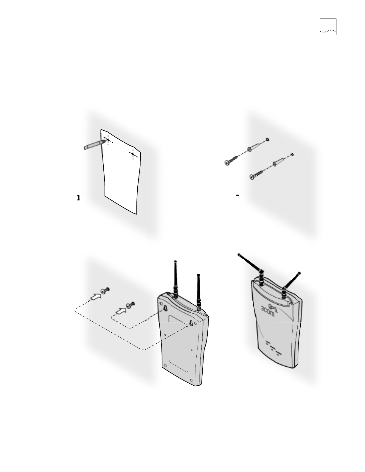
Mounting on a Wall To mount an access point on a wall, follow the instructions on the mounting
template supplied in the box and refer to the following illustration. Preferably,
mount the access point near the ceiling above any obstructions that could block
transmission. Position the antenna so that the arms point out and away from the
access point at a 45˚ angle
Page 14
8 CHAPTER 2: INSTALLING THE ACCESS POINT
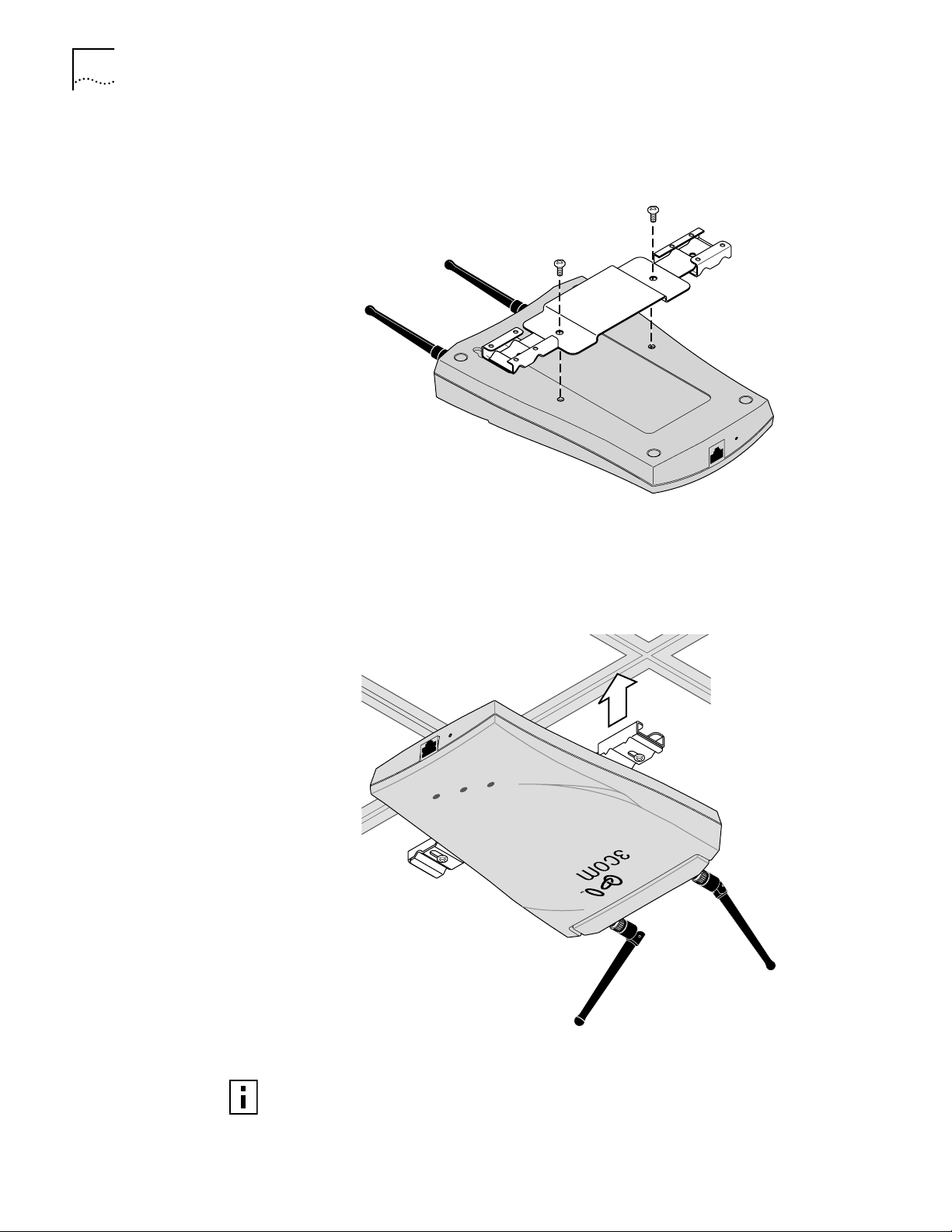
Mounting on a Ceiling To mount an access point to the T-rail grid of an acoustical ceiling, you must first
attach the mounting bracket to the access point as shown.
R
ESET
T
O
P
O
W
E
R
SU
P
P
L
Y
Align the T-rail grips with the ceiling T-rail, adjusting them so they grip the T-rail
snugly. Tighten the screws on the T-rail grip. Position the antenna so that the arms
point down and away from the access point at a 45˚ angle.
R
E
SET
TO P
O
W
E
R
SUP
P
LY
POWER
WIRELE
E
THER
SS
NE
T
NOTE: After installation, there may be some play in the fit of the T-rail grips on the
T-rail. This is likely due to the size of the T-rails but should not prevent a secure
grip.
Page 15
Connecting Power 9
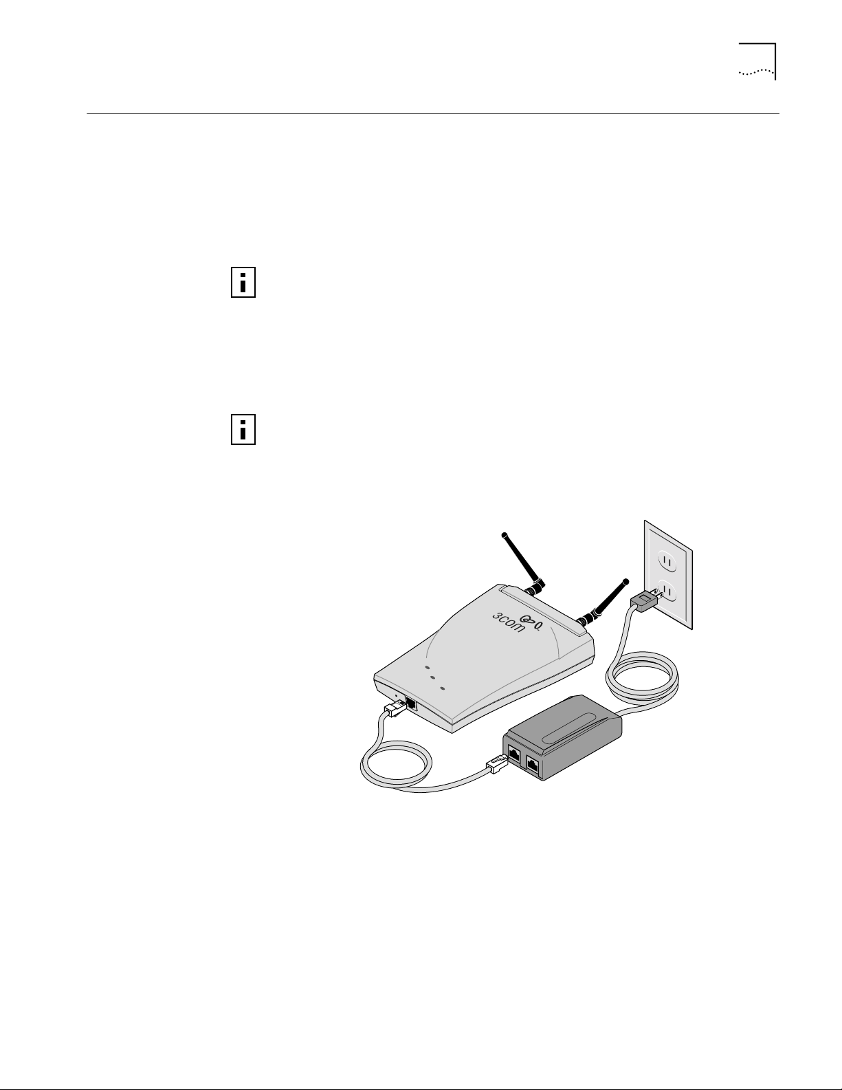
Connecting Power The access point is powered by the 3Com Integrated Power-over-Ethernet power
supply , which pr ovides power over a standard category 5 straight (8-wire) Ethernet
cable. This eliminates the need to run standard power directly to the access point.
The power supply can be located at any point between the access point and the
LAN access port (if you plan to connect to a wired LAN), wherever a convenient
power outlet exists.LEDs light.
The access point is IEEE 802.3af compliant. Before connecting the access point
to your own power-over-Ethernet hub or switch, ensure that your equipment
also complies with the IEEE 802.3af standard.
When you connect the power make sure you connect the cable to the port labeled
To Access Point on the power supply. When the access point receives power, the
LEDs light.
If you supply your own Ethernet cable for connecting power, be sure that it is
standard category 5 straight-through (8-wire) cable that has not been altered in
any way. Use of nonstandard cable could damage the access point.
P
O
W
E
R
WI
R
E
L
E
S
S
E
TH
E
RN
E
R
E
S
E
T
T
T
O
P
O
W
E
R
S
U
P
P
L
Y
T
O
A
C
C
E
S
S
P
O
I
N
T
T
O
H
UB
/
S
W
I
T
C
H
Page 16
10 CHAPTER 2: INSTALLING THE ACCESS POINT
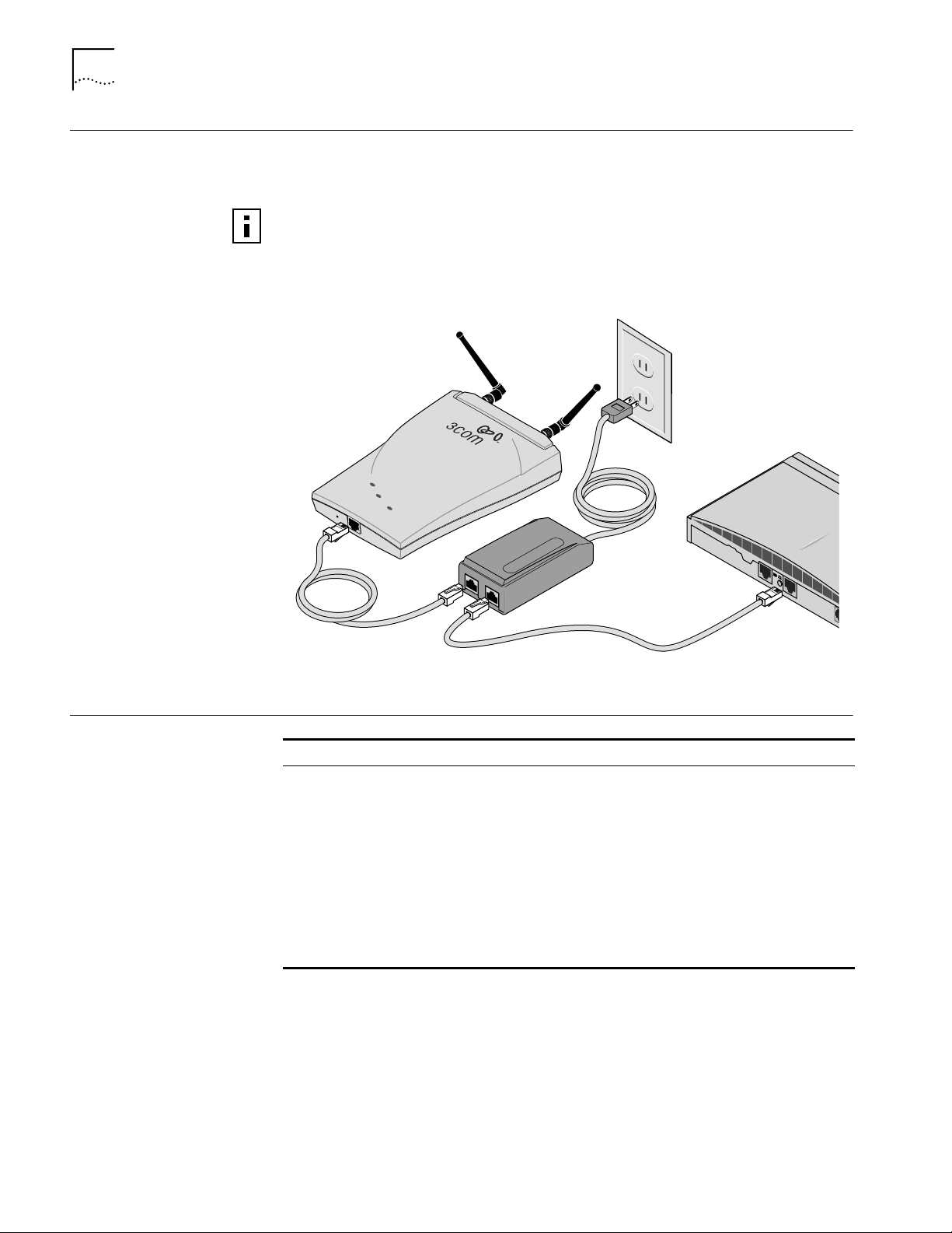
Connecting to an Ethernet Network
Use a standard Ethernet cable to connect the access point to an Ethernet network,
as shown below.
To avoid damaging other components connected to the network, make sure
that the Ethernet cable connected to the LAN port is plugged into the To
Hub/Switch port on the power supply (not the To Access Point port).
P
O
W
E
R
W
I
R
EL
E
S
S
E
T
H
E
RN
E
R
E
S
E
T
T
T
O
P
O
W
E
R
S
U
P
P
L
Y
TO
A
C
C
E
S
S
P
O
I
NT
T
O
H
UB
/
S
WI
T
C
H
E
th
e
rn
e
t
Checking the LEDs
LED Description
Power ■ On—Access point has power.
■ Off—Access point is not receiving power.
Wireless ■ Blinking—The access point is operating. The blink speed ranges from
approximately once every 2.5 seconds to approximately 10 times per
second, depending on the signal strength and transmission speed.
■ Off—The access point is not receiving power.
Ethernet ■ Blinking—Wired LAN traffic is detected. Faster blinking indicates
heavier traffic.
■ Off—There is no wired LAN connection or the access point is not
receiving power.
Page 17

Selecting A Different Antenna 11
Selecting A Different Antenna
Model number 3CWE490 3CWE492 3CWE497 3CWE498
Design and type Omnidirectional
Frequency Range 2.400-2.4835 GHz 2300-2500 Mhz 2300-2500 Mhz 2300-2500 Mhz
Gain 4 dBi 2.5 dBi 4 dBi 8 dBi
VSWR across band < 1.5:1 < 1.35:1 < 1.5:1 < 1.5:1
Distance (coverage)* 2100 feet 1800 feet 2100 feet 3600 feet
Effective Radiated Power
(ERP) @ different power
transmission settings**
Temperature range -40°C to +80°C -40°C to +80°C -40°C to +71°C -40°C to +80°C
Dimensions (inches) 10” (height) 4.25 (diameter) 2.6 x 1.8 x 0.2 5.1 x 4.7 x 1.5
Weight 5.34 oz. 8 oz. 2 oz. 8 oz.
Cable A six-foot accessory cable (model 3CWE480) is required for each of these optional antennas. It
The standard detachable portable antenna supplied with the access point is a
multi-purpose antenna suitable for a variety of environments, including office
LANs, physical plants, and factory floors. If your site has special requirements that
might be served by different types of antenna, four optional antenna models are
available, as shown below:
(fiberglass)
High: 159 mW
Medium: 50 mW
Low: 13 mW
provides the transition from the SMA connector on the access point to the N-type connector
on the antenna. A 20-foot cable (model 3CWE481) is also available.
* Coverage varies depending on building construction.
** See “Setting Data Transmission Properties” on page 27 for information on selecting power
transmission levels.
Ceiling-mount
omnidirectional
High: 112 mW
Medium: 36 mW
Low: 9 mW
Ceiling-mount
hallway
High: 159 mW
Medium: 50 mW
Low: 13 mW
Directional Panel
(indoor/outdoor)
High: 398 mW
Medium: 126 mW
Low: 32 mW
You can order any of the optional antennas by model number from the 3Com
Web site.
Omnidirectional Antenna
The fiberglass omnidirectional
antenna (model number 3CWE490)
is designed for use in harsh indoor
environments. It can be centrally
located on the ceiling to provide
uniform coverage over a wide area.
This antenna features a built-in
matching network that eliminates
the need for a ground plane.
This antenna can be mounted on
the ceiling by means of a standard
ceiling-mount bracket. Before
installing, ensure that access is
available for cable routing.
This antenna does not have an electrical connection between the mask mount and
the coaxial cable shield. However, adding a lightning arrestor will correct this
situation by grounding the outer shield as recommended. Some arrestor designs
provide over -voltage pr otection for the signal sent down the cable. If you use such
Page 18

12 CHAPTER 2: INSTALLING THE ACCESS POINT
a design, be sure that it can pass signals used in the 2.5 GHz signal range. Many
inexpensive units are available with F connectors, but these are typically designed
for cable TV-UHF applications and may degrade the signals in the band used by
the access point.
Ceiling Mount Omnidirectional Antenna
The ceiling-mount omnidirectional
antenna (model number 3CWE492)
is designed to cover large, open
areas. It should be located at or near
the center of the ceiling of a large,
open area (such as an open office
space divided into cubicles) to
provide uniform coverage in all
directions.
It is mounted by means of a single-hole stud mount, and so can be fixed easily to
drop ceiling tiles or to a solid ceiling surface where cable routing access is
available.
This antenna does not have an electrical connection between the mask mount and
the coaxial cable shield. However, adding a lightning arrestor will correct this
situation by grounding the outer shield as recommended. Some arrestor designs
provide over -voltage pr otection for the signal sent down the cable. If you use such
a design, be sure that it can pass signals used in the 2.5 GHz signal range. Many
inexpensive units are available with F connectors, but these are typically designed
for cable TV-UHF applications and may degrade the signals in the band used by
the access point.
Ceiling Mount Hallway Antenna
The ceiling-mount hallway antenna
(model number 3CWE497) has a
bidirectional design that makes it
ideal for use in long corridors. Its
small size means it can provide
extended WLAN coverage with
minimum visibility.
This model includes a bracket for
quick installation on standard
one-inch ceiling rails. In addition,
mounting holes allow for installation
to any flat surface with screws.
Page 19

Selecting A Different Antenna 13
Directional Panel Antenna
The ceiling, wall, and corner-mount
flat-panel directional antenna
(model 3CWE498) provides stable
coverage both indoors and
outdoors.
The panel can be mounted virtually
anywhere and in any orientation.
The flat-panel directional antenna
operates with a gain of 8 dBi.
Depending on the country where
the access point is being installed,
there may be transmit power
restrictions:
■ When using this antenna in the United States, Canada, Mexico, Argentina,
Brazil, Taiwan, Malaysia, New Zealand, Colombia, India, and Peru, no
transmission power restrictions apply.
Connecting an Optional
Antenna
■ In all other countries, transmit power is limited to 100 mW. You must manually
select Low or Medium power from the Data Transmission Properties page of
the configuration management system. See “Setting Data Transmission
Properties” on page 27 for information on manually selecting transmission
levels.
To ensure the physical safety of anyone near the antenna and to prevent damage
to the access point, follow the building codes for antenna installations in your
area. Also, when connecting the optional antenna to the access point, remember
to use only the A-side connector on the access point.
While aligning the antenna, you may want to use the Site Survey tool (preferably
installed on a mobile PC that can be used at the antenna site) to adjust the
Page 20

14 CHAPTER 2: INSTALLING THE ACCESS POINT
antenna to achieve the maximum possible received signal strength. See “Using the
Site Survey Tool” on page 39 for more information.
1 Position the antenna so that there are minimal
"A" side
obstacles between it and any client with which
it will communicate. While maintaining a direct
line of sight between the antenna and a client
is not strictly necessary, such an arrangement
helps to ensure a strong signal. Ensure that
access is available for routing the antenna cable
from the antenna to the access point.
2 If they are installed, remove both arms of the
the standard detachable antenna.
3 Connect one end of the optional antenna cable
to the antenna and secure the antenna in place.
4 Connect the free end of the antenna cable to
the A side connection on the access point.
5 Make certain that the antennas and antenna
masts are appropriately grounded to prevent
injury or damage from lightning strikes.
6 Go to Data Transmission Properties and change
the Radio Antenna settings to Diversity Off. See “Setting Data Transmission
Properties” on page 27.
7 If required in your country or at your site, go to Data Transmission Properties and
change the power transmission settings. See “Setting Data Transmission
Properties” on page 27.
Installing Software Utilities
The 3Com Administrator Utilities CD includes tools and utilities to help you set up
and administer the wireless components of your network. Software tools and
utilities are presented as Tools and Utilities options on the main menu of the CD
and include:
■ Install the Utility Software and Documentation. This option installs the
Wireless Infrastructure Device Manager Tool which you can use to monitor
access points and select devices for administrative changes. It also installs the
Site Survey Tool and product documentation in other languages as translations
become available.
■ Install 3Com TFTP 3CDaemon Server Tool. A TFTP server is required for
firmware upgrades and for backing up and restoring access point configuration
files. This option launches the 3CDaemon installation, which is a resident TFTP
server. You do not have to select this option if you already have a TFTP server
set up. The 3CDaemon server tool can also act as a system log (syslog) server
for the access point.
■ Install 3Com 802.1x Agent. This option installs the Wireless Authentication
Agent for 802.1x support. If you will be using the access point in conjunction
with a RADIUS authentication server, you must install this agent on each
wireless client PC in the network. On systems running Windows XP this agent
is not required because 802.1x support is built into the operating system.
Page 21

Installing Software Utilities 15
■ Install the 3Com Network Supervisor. The 3Com Network Supervisor v. 3.5
(3NS) graphically discovers, maps, and displays network links and IP devices,
including 3Com wireless access points. It is not required for access point
management. It is included for sites that require centralized network
management and are not already using an SNMP-based tool. 3NS maps devices
and connections so you can easily monitor stress levels, set thresholds and
alerts, view network events, generate reports in user-defined formats, and
launch device configuration tools. For use with the Access Point 8000, it should
be installed in conjunction with the 3Com Network Supervisor Advanced
Package v 1.0.
■ Install the 3Com Network Supervisor Advanced Package v 1.0. This is a
supplementary upgrade package that lets the 3Com Network Supervisor
manage additional 3Com equipment. You should install the service pack only
after installing the 3Com Network Supervisor.
■ Install Adobe Acrobat Reader. For users who do not already have Acrobat
Reader 5.0 for viewing the PDF documentation, a current version is included on
the CD.
■ Install Internet Explorer 5.5. A copy of Internet Explorer is included on the
CD in case you are running an older browser. You must have Internet Explorer
5.0 or greater or Netscape 6.0 or greater in order to use the Configuration
Management System. We recommend that you make this the default browser
on the workstation you will use for system configuration and management.
To install a tool from the CD:
1 Turn on the computer and put the 3Com CD in the CD-ROM drive.
2 The setup menu should appear when the CD autostarts. If no menu appears, you
can run the startup program from the Windows Start menu: Start / Run /
d:setup.exe.
3 From the CD startup menu, select Tools and Utilities.
4 Select the item you want to install and follow the instructions on the screen.
Page 22

Page 23

3
ACCESS POINT SECURITY
The advanced security features of the Access Point 8000 address the two primary
aspects of wireless networking security: network authentication and transmission
encryption. The access point provides standardized methods for authentication
and encryption, but also offers innovative technology from 3Com that extends the
standards and makes wireless networking more secure.
The access point can provide a complete stand-alone security solution.
Alternatively, it can be integrated into an enterprise-class security solution,
interacting with a networked RADIUS server and 802.1x-enabled wireless clients.
Upper-Layer Authentication
The basic authentication schemes defined in the 802.11 standard are limiting
because they do not provide a way to centralize authentication information into a
central server. Upper layer authentication solves this problem. Through the use of
the Extensible Authentication Protocol (EAP), the access point supports a number
of upper layer authentication schemes, including EAP-MD5, EAP-TLS, and 3Com
Serial Authentication.
EAP-MD5 EAP-MD5 provides a simple way to centralize client network authentication
information in a RADIUS server. Under this scheme, the server does not require
certificates or other security information installed on client machines. At login, the
RADIUS server verifies the username and password provided by the user. Once the
user is authenticated, the server informs the access point of successful
authentication and data traffic from the client is allowed to pass to the wired
network. EAP-MD5 provides authentication only. It is possible to configure the
access point to use any of the 802.11 standard encryption mechanisms along with
EAP-MD5 authentication. EAP-MD5 is a one-way authentication scheme: it
authenticates the client to the server, but does not authenticate the server to the
client.
EAP-MD5 is supported by the 3Com 802.1x agent (described below) and is built
into the Windows XP operating system.
EAP-TLS EAP-TLS provides both authentication and dynamic session key distribution.This
authentication scheme provides mutual authentication between the client and
server. A unique X.509 certificate must be generated for each network user. In
addition, the certificate must be installed on all client PCs that will be used to log
onto the network. Both a client and a server certificate are exchanged as part of
authentication.
Once authenticated, the server informs the access point and data traffic from the
client is allowed to pass to the wired network. As part of authentication, the client
and TLS server derive session-specific keys based on information shared between
Page 24

18 CHAPTER 3: ACCESS POINT SECURITY
them. After successful authentication, the TLS server securely sends the session
keys to the access point and user data is allowed to pass. EAP-TLS is currently
supported only under Windows XP.
3Com Serial
Authentication
Serial Authentication, a 3Com-proprietary upper layer authentication mechanism, uses a two-phase process involving both EAP-TLS and EAP-MD5
■ In the first phase, the wireless client and the RADIUS EAP-TLS server mutually
authenticate each other. All clients can authenticate to the TLS server because
a common certificate is provided during software installation. Successful
completion of this phase establishes dynamic session keys that protect
subsequent communication between the wireless client and access point.
■ In the second phase, the server can securely use EAP-MD5 to authenticate the
user. Once authenticated, the server informs the access point and data traffic
from the client is allowed to pass to the wired network.
3Com Serial Authentication also includes optional dynamic session-key renewal,
which greatly enhances system security. Dynamic key renewal means that,
following the initial upper layer authentication, the client and the access point
periodically update the session keys used for encryption.
3Com’s Serial Authentication method provides obvious advantages. By combining
encryption key distribution and a secure network authentication, it makes use of
two complementary authentication schemes. Additionally, the client and the
access point dynamically update session keys while the network session is in
progress. Because Serial Authentication is a 3Com proprietary scheme, it must be
used with the 3Com Wireless LAN PC Card (model 3CRWE62092A) and the 3Com
Access Point 8000. Serial authentication is supported by the 3Com 802.1x agent
(described below).
Additional Security
Configuration Options
If you choose not to use an upper layer authentication scheme, 3Com’s security
solution also supports the authentication and encryption methods described
below.
Open Network. The open-network option assumes that neither authentication
nor encryption are required. No security is used.
40-bit Shared Key Encryption. This option is compatible with Wi-Fi certified
equipment from other vendors. Encryption keys must be set up on both the client
and the access point. The network administrator sets up a fixed set of encryption
keys for the wireless network and supplies users with an encryption string or a set
of hexadecimal keys. This option can be used with local access point
authentication or with EAP-MD5 RADIUS authentication.
128-bit Shared Key Encryption. This option is compatible with 128-bit shared
key from most vendors, including 3Com, Agere, and Cisco. The network
administrator sets up encryption keys for the wireless network and supplies users
with an encryption string or hexadecimal keys. Y ou must set up encryption keys on
both the client and access point. This option can be used with local access point
authentication or with EAP-MD5 RADIUS authentication.
Page 25

802.1x RADIUS Support 19
3Com 128-bit Dynamic Security Link Encryption. 3Com’s proprietary 128-bit
Dynamic Security Link is built into the access point and permits user-level
authentication. This option can be used only with local access point
authentication. Users must log in with username and password. (The access point
username and password database can support up to 1000 names.) Once the user
is authenticated, the access point dynamically creates a unique 128-encryption key
for the user for that session. Encryption keys are generated automatically and so
do not need to be supplied. To take advantage of this security setting, clients must
use a 3Com Wireless LAN PC Card (model 3CRWE62092A).
802.1x RADIUS Support
Using the Wireless
802.1x Agent
The IEEE 802.1x standard specifies a general method for the provision of
port-based network access control. It provides an architecture framework for
User-RADIUS authentication through an authenticator such as a wireless access
point or a switch. The access point supports any RADIUS implementation
compliant with RFC 2865 and following standard EAP, RFC 2284, 2716, and 2548
protocols. This includes support for port-based network access control, which
permits standard security protocols such as EAP and RADIUS to provide centralized
user identification, authentication, dynamic key management, and accounting.
(The access point supports RADIUS Accounting per RFC2866: Username, Start
time, Stop time, and Packet input/output.)
3Com does not supply RADIUS software or configuration instructions other than
what is applicable for access point configuration. Refer to your system
administrator for additional third-party software and configuration information.
The access point supports any RADIUS server that complies with RFC 2865 and
follows standard EAP, RFC 2284, 2716, and 2548.
3Com provides a software utility to allow Windows clients to authenticate to the
Access Point 8000 using either EAP-MD5 or 3Com Serial Authentication. The
802.1x agent can be used with any vendor’s PC card, but to take advantage of
3Com’s Serial Authentication, it must be used with a 3Com Wireless LAN PC Card
(model 3CRWE62092A) that has been upgraded to the latest firmware. A copy of
the agent must be installed on each client computer
Authentication and
Login
Use the 3Com CD to install the wireless 802.1x agent on systems running under,
Windows 98, Windows 98 SE, Windows ME, Windows NT 4.0 with Service Pack
6a, Windows 2000, or Windows XP. Systems running under Windows XP include
support for EAP-MD5 and EAP-TLS. On Windows XP, the 802.1x agent is only
required when using 3Com’s Serial Authentication.
Authentication is initiated by associating to the access point. Alternatively,
authentication can be manually initiated by selecting Start from the 802.1x agent
menu. At login, the agent prompts for user name and password. The user name
and password must match the name and password maintained by the RADIUS
server.
When the agent is running, a status icon in the system tray monitors the
authentication process. The appearance of this icon changes to reflect the current
state of the authentication process. If the user hovers the mouse over the icon, a
tool tip also appears to indicate the current authentication status.
Page 26

20 CHAPTER 3: ACCESS POINT SECURITY
If authentication fails, the access point will continue to block traffic from that
client. The user may also manually log off and stop the agent, which suspends the
authentication process until the client manually logs on again or intentionally
re-associates with an access point. When a computer is logged off manually, the
access point blocks traffic from the client until the client logs on again.
Note that your authentication status icon may not necessarily reflect your
connection status. The status icon cannot be updated if the authenticating access
point cannot communicate with your computer. For example, you may have left
the coverage area of a subnet maintained by the access point in your network. If
you have roamed to the coverage area of another type of access point, the status
icon will continue to reflect the status it displayed when it was last in contact with
the authenticating access point. If you are unsure of your authentication status:
■ Log off and log on again.
■ Check the adapter status to see if it is still associating with an access point.
802.1x Client Properties Use the Properties window to configure the agent for the type of authentication the client should use.
Enable network access control using IEEE 802.1X. This box must be checked if
you are using authentication with your RADIUS server. If this box is unchecked, the
remainder of the window is grayed out.
Network Adapter. Use this field to identify the network adapter to use for
connections requiring authentication. The list box lists all the network adapters
found in the computer. The highest level of security, 3Com’s Serial Authentication,
is available when the 3Com Wireless LAN PC card is installed and selected.
Authentication Method. This field lets you specify the authentication method
used for this connection. The wireless authentication agent supports two types of
authentication:
■ EAP-MD5
■ Serial Authentication
The client and the access point must have the same authentication settings. If you
switch from serial authentication to EAP-MD5, or from EAP-MD5 to serial
authentication, clients will have to re-associate to the access point. When using
serial authentication with a 3Com Wireless LAN PC card, you should configure the
card to use “no security.” This is because the 802.1x agent configures the security
on the card.
Serial Authentication Advanced Configuration. This window lets you
configure how the 802.1x agent handles certificates received from the EAP-TLS
server. The first option enables verification of authentication server certificates.
When this option is disabled, the 802.1x agent will not validate authentication
server certificates. Disabling this verification results in one-way authentication of
the client to the server, instead of the normal mutual authentication that takes
place in EAP-TLS.
Two settings affect the way the 802.1x agent verifies the authentication sever
certificate. The first option allows you to import a certificate for a trusted server.
The second option causes the 802.1x agent to prompt for user validation
Page 27

Using the Wireless 802.1x Agent 21
whenever an untrusted certificate is received. The 802.1x agent remembers the
last trusted certificate, whether imported or manually verified, and automatically
accepts that certificate.
Page 28

Page 29

4
CONFIGURING THE ACCESS POINT 8000
If the access point factory default configuration does not meet your network
requirements, or if you want to customize the configuration settings, you can use
these tools, which are included on the 3Com Access Point 8000 Installation CD, to
change the configuration.
■ 3Com Wireless Infrastructure Device Manager—As a discovery tool, the
Device Manager finds all of the 3Com wireless infrastructure devices on the
same network segment as your workstation. It starts up with a hierarchical
representation of the wireless infrastructure. You can select a device from this
display, view its properties, and open the device for configuration and
management through its configuration management system.
■ 3Com Network Supervisor (3NS) — 3Com Network Supervisor graphically
discovers, maps, and displays network links and IP devices, including 3Com
wireless access points. It maps devices and connections so you can easily
monitor stress levels, set thresholds and alerts, view network events, generate
reports in user-defined formats, and launch device configuration tools. When
your network changes, you can prompt 3Com Network Supervisor to
regenerate the appropriate part of the map to ensure that you have current
information. Automated operations, intelligent defaults, and the ability to
detect Network misconfigurations and offer optimization suggestions make
this application ideal for network managers at all levels of experience. Together
with the optional 3Com Network Supervisor Advanced Package, 3Com
Network Supervisor Version 3.5 helps businesses manage larger networks and
easily upgrade agent software in 3Com devices. For detailed information on
features and installation, refer to the Network Supervisor user guide which is
installed with the Network Supervisor software.
Installing the Device Manager
■ 3Com 11 Mbps Wireless LAN Access Point 8000 Configuration
Management System—The Configuration Management System is a set of
Web pages stored on the access point that lets you view and modify the access
point configuration settings through the Web browser on your workstation.
(You must have Internet Explorer 5.0 or later or Netscape 6.0 or later installed
as the default browser on your workstation.)
The 3Com Wireless Infrastructure Device Manager can be installed on any
Windows client or on a desktop computer wired to the LAN.
1 Turn on the computer.
2 Put the 3Com CD in the CD-ROM drive.
3 In the main screen, click Tools and Utilities.
4 In the next screen, click Install Utility Software and Documentation.
5 Follow the instructions on the screens to complete the installation.
Page 30

24 CHAPTER 4: CONFIGURING THE ACCESS POINT 8000
6 After you install the device manager, you can launch it by double-clicking the
device manager icon on your computer desktop, or, from the Windows Start
menu select Start / Programs / 3Com Wireless Infrastructure Device Manager /
3Com Wireless Infrastructure Device Manager.
Launching a Wireless
Device Configuration
Make sure that the 3Com Wireless Infrastructure Device Manager is installed. The
device to be configured must be either wired to the network, associating with the
wireless network, or connected directly to the computer, and it must be connected
to power. If more than one device using the factory default name is connected,
make a note of the MAC address of the device you want to select so that you can
identify it in the device manager.
If you do not have a DHCP server on your network, it can take up to one minute
for a device to become discoverable after it has been powered up.
1 To launch the device manager, select Start /Programs /3Com Wireless/Wireless
Infrastructure Device Manager.
If you have more than one network adapter installed on your computer, you may
be prompted to choose a network adapter. Choose the appropriate adapter and
click OK.
The Wireless Network Tree appears in the 3Com Wireless Infrastructure Device
Manager window. The tree lists all WLAN service areas on the network and
expands to show the 3Com wireless LAN devices that are associated to each
service area. Devices in a different subnet than your computer are identified with
exclamation points (!). You can refresh this display by clicking Refresh. You should
refresh the display, for example, after you change a device IP address.
2 In the Wireless Network Tree, select the device you want to configure.
If more than one wireless LAN device appears in the tree and you ar e not sure that
you have selected the right one, click Properties and check the MAC address to
verify that it is the one you want.
3 Click Configure.
■ If the selected device is on the same subnet as your computer, the
Configuration Management System main page appears in your Web browser.
(If a password is set on the device, enter it when prompted.)
■ If the selected device is on a different subnet, the Pre-IP Configuration Wizard
is activated automatically. This wizard lets you configure the IP settings for the
selected wireless device. It proposes IP address and subnet mask settings
derived from your computer’s settings, so the selected device will then reside
on the same subnet as your computer. You can accept the suggested settings
or change them as required.
The next window prompts for an administrative password to allow the new IP
address to be set. When the units are shipped from the factory, there is no
administration password and you should leave the password field blank. If an
administration password has been set for the device, enter the password and
click Next. The Configuration Management System main page appears in your
Web browser.
Page 31

Using the Configuration Management System 25
The following table describes the functions of the buttons in the 3Com Wireless
Infrastructure Device Manager window.
Button Description
Properties Displays the following properties of the selected device: Device Name, Device
Configure Launches the Configuration Management System for the selected device. If
Refresh Scans the network and displays the connected 3Com 11 Mbps Wireless
Choose NIC If your computer has more than one network interface card installed, allows
Close Closes the device manager window and ends the session.
Help Launches the device manager help page in your browser.
Type, Wireless LAN Service Area (ESSID), IP Address, Subnet Mask, and MAC
Address.
the selected device is on a different subnet, you are prompted to assign an
address on the same subnet as your computer.
LAN devices.
you to choose which card you want to use.
Using the
Configuration
Management System
From the Configuration Management System main page, you can select which
configuration page to view by clicking on the page names in the navigation tree in
the left-hand frame. The corresponding content is displayed in the main window.
Each page has a question mark icon in the upper-right corner that you can use to
display help on the contents of that page.
The Configuration Management System is password protected. If you are starting
it for the first time, it asks you to enter and confirm an administrative password. If
the device has an administrative password, the default Web browser prompts for
username and password (you need not enter the username – only the password is
required).
Any changes you make on a configuration page must be saved before you leave
that page. Otherwise, the settings will revert back to the current settings. New
settings are applied to the device as each save operation is completed.
The following table summarizes the Access Point 8000 configuration pages.
Page Group Description
System Configuration The system configuration pages are concerned with high-level
network management, including access point properties, network
properties, and data transmission properties.
Security The Security pages allow you to set up authentication and encryption,
control access, and set up access point RADIUS server parameters.
Management The Management pages let you configure the access point for use
with third-party SNMP management programs, specify the TFTP
server you will use for various administrative functions, and set up the
access point system log.
Tools Use the Tools pages to upgrade access point firmware, change the
administration password, restore factory defaults, and reset the
access point.
Statistics The Statistics pages display various categories of operational and
performance statistics associated with the access point.
Page 32

26 CHAPTER 4: CONFIGURING THE ACCESS POINT 8000
Page Group Description
System Status The System Status pages show currently associated clients, general
information about the access point, and details about wireless
configuration settings.
Changing Access Point Properties
Setting Network Properties
The Access Point Properties page displays the properties of the selected access
point. You can change properties by entering values in the fields and clicking the
radio buttons described below. When you are finished, click Save.
■ Device Name—This name appears on the device manager window.
■ Device Location—Optionally, you can enter the location of the access point.
■ Wireless LAN Service Area—To enable clients to roam among multiple
access points, the access points must have identical WLAN service areas. To
maintain wireless association, the WLAN service area on the client and the
access point with which it is associated must match exactly. If you are
associated with the access point that you are configuring and you change the
access point WLAN service area, make sure to change the client WLAN service
area also.
The Network Properties page lets you change the settings shown below.
■ Network Setting—This setting lets you change the IP address of the access
point.
To let the access point get an IP address automatically from a DHCP server, click
Obtain an IP address automatically and click Save.
To specify an IP address, click Specify an IP address, enter the IP address
parameters in the spaces provided, and click Save.
If you change the IP address, you cannot continue to configure the access point
using the old IP address. If you want to continue configuring this access point,
you must close your browser and start a new configuration session.
When you specify an IP address, the access point cannot act as a DHCP server.
Make sure that clients are using IP addresses on the same network.
■ Wireless DHCP Server—If your wired network has a DHCP server, it is
recommended that you use it. However, the access point provides a DHCP
server that can automatically assign addresses to clients in a simple, all-wireless
network.
The access point’s default IP address is 169.254.xxx.1, where xxx is the last byte
of the access point’s MAC address. When it is acting as a DHCP server, the
access point can assign up to 253 IP addresses to currently associated wireless
clients. The IP addresses range from 169.254.xxx.2 to 169.254.xxx.254.
If the access point detects that another DHCP server is available, all wireless
clients get IP addresses from that DHCP server.
If your wired LAN DHCP server goes down, the access point assigns IP
addresses after the lease periods on the previous IP addresses expire.
To let the access point act as a DHCP server when there is no other DHCP server
available, click Enable and click Save.
Page 33

Setting Data Transmission Properties 27
To turn off the access point DHCP server capability r egardless of whether or not
another DHCP server is available, click Disable and click Save.
■ Gateways—You can specify up to three additional gateway IP addresses.
These settings are optional. (Only the default gateway is required).
Setting Data Transmission Properties
The Data Transmission Properties page lets you select radio channel settings and
performance settings. This page contains a link to the Advanced Settings page,
where you can set additional data transmission properties.
■ Clear Channel Select—Lets the access point find a channel automatically.
When this option is enabled, the access point scans the primary channels to
determine the traffic on those channels and chooses the channel with the least
number of packets.
By default, the access point automatically selects the optimal channel for
wireless transmissions. The access point will select between channels 1–13. If
your network supports clients that do not acknowledge 13 channels, you will
have to manually select a channel within the reach of those clients. For
example, if you have clients that only support channels 1–11, you must
manually set the access point to use a specific channel in that range.
If France, you must manually select from channels 10–13.
To select a specific channel, click the off (Specify the channel) button and
choose a channel from the Channel list.
■ Network Traffic Accelerator—To increase performance, click On (enhanced
performance). If you experience problems when equipment other than 3Com
11 Mbps Wireless LAN equipment is being used, click Off.
■ Data Preamble—To increase performance, click Short (enhanced
performance). When equipment that does not support short preamble is also
being used, click Long.
■ Data Rate—These settings configure the data rates used for wireless
transmissions. By default, the access point selects the best data rate for the
current connection.
If “Automatically set the best data rate” is selected, the Data Rate cannot be
selected manually.
If “Manually set the data rate” is selected, the 5.5Mbps and 11Mpbs options
become active. You may not alter the settings for the 1Mbps and 2Mbps rates
since these rates must always be available to transmit certain types of wireless
traffic.
The data rates may either be Required or Optional. When the data rate is set to
Optional, the AP determines if it is appropriate to use that data rate or if the
signal strength requires a lower data rate to be used. If the data rate is set to
Required, the AP does not have the option to modulate to a lower data rate,
and may lose connection with clients that cannot support the higher data rate.
■ Beacon Period—The beacon period sets the amount of time between
beacons sent out from the AP. Normally you will not have to change this
setting, although it can be useful in extremely noisy RF environments.
■ Radio Antenna—These settings determine whether the radio will use one or
two antennas. If the user attaches an external antenna, this parameter should
Page 34

28 CHAPTER 4: CONFIGURING THE ACCESS POINT 8000
be set to Diversity Off. Generally, if the access point is using the standard
detachable antennas, this parameter should be set to Diversity On to maximize
the transmission and reception qualities of using both antennas.
■ Transmit Power—You can adjust the transmit power between these settings:
High: +18 dBm at the connector
Medium: +13 dBm at the connector
Low: +7 dBm at the connector
These settings may need to be adjusted for compatibility with different types of
external antennas that have different gains. These adjustments may be
required to be legally compliant with the communications regulations in certain
countries. For example, if you are using a high-gain antenna such as the
optional flat-panel directional antenna (model 3CWE498) in the United States,
Canada, Mexico, Argentina, Brazil, Taiwan, Malaysia, New Zealand, Colombia,
India, and Peru, no transmit power restrictions apply. If you are using it in any
other country, however, you must manually select Low or Medium power.
Setting Advanced Data Transmission Properties
The Advanced Settings page provides additional features for controlling
client access and communications among clients.
Changing the advanced settings causes the access point to reassociate
with clients, which can temporarily disrupt their network operations.
■ Load Balancing—Allows you to specify the maximum number of clients that
can associate with the access point at the same time. To specify a number, click
On, enter a number between 1 and 256, and click Save. To disable load
balancing, click Off. When load balancing is Off (the default) up to 256 clients
can associate with the access point. If you specify a small number of clients, it is
recommended that you also choose the shortest possible time in the Client List
Timeout setting.
■ Client-to-Client Blocking—When this setting is On, clients associating with
the access point are prevented from communicating with one another,
providing client privacy in public access situations. When this setting is Off,
clients associating with the access point can communicate.
■ Client List Timeout—This setting determines the length of time a client
remains in the access point’s list of associated clients after ending the
association. You can choose a timeout setting from the list. It is recommended
that you choose the shortest possible timeout setting, especially if you have
specified a small number of clients in the Load Balancing setting.
■ Broadcast WLAN Service Area Name (ESSID)—When this mode is enabled
(the default mode), the access point WLAN service area is visible to
wireless clients.
When this mode is disabled, the access point WLAN service area is invisible to
wireless clients. Clients that support association with access points in privacy
mode can associate with the access point by specifying the access point’s
Wireless LAN Service Area.
Click On to enable broadcasting. Click Off to disable broadcasting.
Page 35

Setting up Security 29
Setting up Security The Encryption page lets you select the type of security to be used on the access
point. The page is divided into Security Settings, which determine the type of
access authentication, and Access Point Encryption Settings, which determine the
type of encryption used if the access point is handling encryption. To maintain
wireless association, the encryption settings on clients and all the access points
they associate with must match exactly.
In addition to providing wireless encryption, access point security can be
integrated with upper layer authentication provided by a RADIUS server on the
wired LAN using IEEE 802.1x support.
Security Settings The following security settings are available on the Encryption page. Security
settings that use access point encryption also require you to select from the
options available under Access Point Encryption Settings, which are described in
“Access Point Encryption Settings”.
■ Access Point Local Authentication/Encryption—Disables upper-layer
authentication, so the access point handles both authentication and
encryption. It can be used with any of the encryption options described in
“Access Point Encryption Settings”.
■ RADIUS EAP-MD5 Authentication with Access Point Encryption—Enables
RADIUS authentication using MD5 (username-password) authentication. It can
be used with No Security (Open System), 40-bit Encryption Shared Key (Wi-Fi),
or 128-bit Encryption Shared Key as described in “Access Point Encryption
Settings”.
■ RADIUS Serial Authentication with Dynamic Encryption Key—Enables
mutual RADIUS authentication implementation, which allows client and
RADIUS to mutually authenticate (EAP-TLS) and perform user authentication
(EAP-MD5). You can select either 40-bit or 128-bit Dynamic Encryption.
Selecting Auto-Session Key Renew causes the access point and clients to
periodically change session keys, greatly enhancing security.
RADIUS EAP-TLS Authentication with Dynamic Encryption Key
(Windows XP only)—Enables certificate-based mutual RADIUS authentication
with 40-bit or 128-bit Dynamic Encryption. This setting is supported for clients
running under Windows XP.
■ Access Point Local MAC Authentication/Encryption—Enables client
authentication through a list of MAC addresses stored on the access point.
Only clients whose MAC addresses are on the list can associate with the access
point. This option can be used with No Security (Open System), 40-bit
Encryption Shared Key (Wi-Fi), or 128-bit Encryption Shared Key as described in
“Access Point Encryption Settings”. For details on how to set up the access list,
see “Setting up a MAC Address Access List” on page 31.
■ RADIUS MAC Authentication with Access Point Encryption—Enables
client authentication through a list of MAC addresses stored on a RADIUS
server. Only clients whose MAC addresses are on the list can associate with the
access point. This option can be used with No Security (Open System), 40-bit
Encryption Shared Key (Wi-Fi), or 128-bit Encryption Shared Key as described in
“Access Point Encryption Settings”. For details on how to create the MAC
authentication list on the RADIUS server, see RADIUS documentation.
Page 36

30 CHAPTER 4: CONFIGURING THE ACCESS POINT 8000
Access Point Encryption
Settings
The following encryption settings are available on the Encryption page. These
encryption settings are for Security settings that use access point encryption:
■ No Security (Open System)—No encryption is used. The network
communications could be intercepted by unintended recipients.
■ 40-bit Encryption Shared Key (Wi-Fi)—This option encrypts the wireless
transmissions to protect data, but still permits communication among
compatible wireless LAN clients and access points from third-party
manufacturers.
40-bit Encryption Shared Key (Wi-Fi) security requires you to set up encryption
in one of the following ways:
■ An encryption string is a string of characters between 6 and 30 characters
long. The string can be any combination of letters and numbers and is case
sensitive. The encryption string can be used only with other 3Com 11 Mbps
wireless PC Cards and Access Points.
■ Hexadecimal keys are sequences of hexadecimal digits arranged into four
keys. A hexadecimal digit may be a letter from A to F or a number from 0 to
9. This type of encryption is compatible with equipment from other
manufacturers that use Wi-Fi certified 40-bit encryption.
■ 128-bit Encryption Shared Key—This setting is compatible with 3Com
AirConnect products and products from other vendors, including Agere
and Cisco. 128-bit Encryption Shared Key security requires you to set up an
encryption string or hexadecimal keys as described for 40-bit Encryption Shared
Key (Wi-Fi).
Setting up a User
Access List
■ 128-bit Dynamic Security Link—This setting requires that you select Access
Point Local Authentication/Encryption option under Security Settings. 128-bit
Dynamic Security Link is the highest level of access point local security,
requiring a user name and password to access the wireless LAN. The user name
and password set up on the access point must match those set up on the
client. Each network session creates a unique, one-time encryption code. If you
choose this type of security, you must also set up the user access list (see
“Setting up a User Access List”). If you check the Require Windows user
authentication check box, clients will be required to enter a user name and
password every time they associate with the network. If you leave this box
unchecked, the system will authenticate clients based on the user access list
and the saved passwords on the clients.
The user access list is required only if you configure an access point for 128-bit
Dynamic Security Link on the encryption page. There must be at least one entry in
the List.
The user access list determines which users are allowed to pass data to the access
point. Through this list, you can perform high-level management of up to 1000
user accounts.
■ Adding users—To add a user, you must supply a username and password for
each new user. The username and password pairs must match the user names
and passwords of any clients trying to associate with the access point.
Page 37

Setting up a MAC Address Access List 31
■ Deleting users—To delete users, check the boxes next to the users you want
to delete and click Delete. If you click Reset, all checked boxes are cleared and
you may reselect which users to delete from the list.
■ Modify Passwords—To modify a password, select the button next to the user
name click Change. Change the password in the spaces provided and click OK.
If you click Undo, all password fields are cleared and you may type another
password.
Setting up a MAC Address Access List
Defining RADIUS
Servers
The MAC address access list is only required if you use the Access Point Local MAC
Authentication/Encryption security setting. Up to 1000 client MAC addresses can
be stored in this list. If a client’s MAC address is not on the list, that client cannot
associate with the access point.
■ Adding MAC addresses—You must supply a MAC address for each client.
■ Deleting MAC addresses—To delete MAC addresses, check the boxes next to
the addresses you want to delete and click Delete. If you click Reset, all
checked boxes are cleared and you may reselect which users to delete from
the list.
The RADIUS Server Setup page lets you define the servers to be used for RADIUS
authentication and accounting functions. These include RADIUS authentication
servers, dynamic key exchange servers, and accounting servers. If you enter an
invalid IP address for any of the servers, an error message is displayed. Once an
accounting server is set up, you can turn accounting on or off from this page. If
the servers are set up and accounting is turned off, the settings remain saved.
To set up the servers, you will need to specify a valid IP address as well as the port
and shared secret for the primary and secondary servers your network uses for
authentication, dynamic key exchange, and accounting. Secondary servers are
optional. The authentication scheme implemented at your site determines which
servers you must set up:
Configuring for SNMP
Management
■ If you are using EAP-MD5, you must set up the RADIUS authentication server
information.
■ If you are using EAP-TLS, you must set up the dynamic key exchange server
information.
■ If you are using Serial Authentication, you must set up both the RADIUS
authentication server and the dynamic key exchange server.
Configuration of the RADIUS accounting server is optional.
The SNMP Management page lets you set up the configuration for using the
access point in conjunction with third-party SNMP management programs. From
this page, you can:
■ Modify the Read Only (default “public”) or Read/Write (default “private”)
community names. Activation of either Modify button displays the
corresponding page where the community names can be set.
■ Identify one or two host machines to receive SNMP traps.
Page 38

32 CHAPTER 4: CONFIGURING THE ACCESS POINT 8000
■ Identify which traps to send to the trap host or hosts.
Defining a TFTP Server A TFTP server must be set up in order to perform firmware updates, backups, and
restores. The TFTP Setup page identifies the TFTP server that will be used. If you do
not have a TFTP server, you can install the one shipped with the access point. Use
the 3Com CD (Tools and Utilities options) to install the 3CDaemon TFTP server.
You must supply the IP address of the TFTP server computer. The default TFTP
client port number is 69, the TCP/UDP port number that is most commonly used
for TFTP, although you can change this to a different port number if required.
Setting up a
System Log
The System Log page lets you set up one or two computers for saving log files and
to enable or disable logging. Log files are not viewable through the Configuration
Management System or the access point, and so must be accessed from a host
computer running a syslog server.
By default, logging is off. If you turn on logging, you must specify at least one
host. The access point sends log information to the host using syslog through port
514 (the TCP/UDP port number that is most commonly used for syslog).
If you do not have a syslog server, you can install the one shipped with the access
point. Use the 3Com CD (Tools and Utilities options) to install the 3CDaemon
syslog server.
Upgrading the System You can download system firmware upgrade files from the 3Com Web site at
http://www.3com.com and install those upgrades on the access point. You must
have a TFTP server set up on which to store the upgrade file. This is the server
specified on the TFTP setup page.
To avoid problems that could occur if a wireless association were interrupted
during the upgrade, it is recommended that you perform the upgrade from a
computer that is wired to the LAN.
To locate an upgrade file and download it to your computer:
1 Log on to the 3Com Web site at http://www.3com.com.
2 Navigate to the product support page.
3 Navigate to the software download page and locate the file you want
to download.
4 Follow the instructions to download the file into a directory on your computer.
5 Copy or move the file to the TFTP server upload/download directory.
To install an upgrade:
1 Launch the access point configuration.
2 Under Tools, click Upgrade System.
3 In the Upgrade System page, make sure the TFTP server IP address is correct.
If you need to change the TFTP server address, click Change. In the TFTP Setup
page, enter the server address and click Save. Then under Tools, click
Upgrade System to return to the Upgrade System page.
Page 39

Changing the Administration Password 33
4 Click the Access Point Firmware check box.
5 Enter the name of the upgrade file that you downloaded earlier.
6 Click Upgrade Now.
The upgrade file is copied from the TFTP server to the access point and the access
point restarts using the new upgrade.
Changing the Administration Password
Restoring Factory Defaults
Resetting the Access Point
When you log in for the first time, the Configuration Management System asks
you to supply an administration password. Enter a password of at least 6-16
alphanumeric characters. If you choose not to use a password, be sure to check
the check box instead.
To change the administration password, under Tools click Change Administration
Password. In the Change Administration Password page, enter the current
password and the new password in the spaces provided and click Save.
You can remove an existing administrative password by selecting Change
Administration Password and leaving the new password fields blank.
The Restore Factory Defaults page allows you to erases the access point’s current
configuration and restore the factory default settings.
You can also erase the current configuration and restore the factory default
settings by pressing the end of a pin or paper clip into the Reset hole on the front
of the access point (near the RJ-45 connector) and holding it in for five seconds.
The Reset Wireless Access Point page allows you to reboot the access point
without affecting the current configuration settings. You can also reset the
hardware by disconnecting and reconnecting the power.
Backing up
Configurations
Restoring
Configurations
Access Point configurations can be saved as data files and later used to restore the
access point configuration. The Backup Configuration page lets you save access
point settings in an external file. (You must have a TFTP server set up on which to
store the backup file. This is the server specified on the TFTP setup page.)
When you back up a configuration, you must supply the name of the file that the
configuration is saved to. This file will be written to the upload/download directory
of the TFTP server. If you need to change the TFTP configuration, click the Change
button to open the TFTP Setup page.
Use Restore Configuration to restore settings from a previously saved backup file
to the current access point. If you select All Configuration Settings, the saved
configuration is restored completely.
If you select Only Template Settings, only general configuration parameters such
as WLAN service area, data transmission settings, security settings, dynamic
security link user access list, RADIUS server settings, and management setup
information are restored. Template settings would be used in common by several
access points in a network and provide an easy way to reconfigure all access
Page 40

points in a network. Template parameters do not affect nor overwrite settings
unique to individual access points, such as device name, location, IP addresses,
and administration passwords.
Viewing Statistics The statistics pages display various categories of operational and performance
statistics associated with the access point. The values do not update dynamically,
but you can update them at any time by refreshing the display.
■ RF Statistics—Displays performance data for the radio transmissions to and
from the access point. The statistics related to transmissions from the access
point are listed in the Transmitted table on the left. Statistics related to radio
signals received by the access point are listed in the Received table on the right.
The RF statistics include the following numbers:
■ unicast frames successfully transmitted and received
■ broadcast frames transmitted and received
■ multicast frames transmitted and received
■ encrypted frames transmitted and received
■ frames fragments transmitted and received
■ beacon frames transmitted and received
■ ACK frames transmitted in response to successfully received frames
■ frames transmitted with corresponding ACK frames successfully received
■ RTS frames successfully transmitted and received
■ frames for which no CTS frames were received in response to RTS frames
being sent
■ CTS frames received in response to an RTS
■ frames transmitted that did not have their corresponding ACK packets
successfully received
■ frames that were retransmitted
■ frames received with checksum error
■ duplicate frames received
■ frames received with the WEP subfield of the Frame Control field set to one
and the WEPOn value for the key mapped to the TA's MAC address;
indicates that the frame should not have been encrypted or that frame is
discarded because the receiving STA does not support the privacy option
■ frames received with the WEP subfield of the Frame Control field set to one
and the value of the ICV not matching the ICV value calculated for the
contents of the received frame
■ Ethernet Statistics—Displays performance data for the wired Ethernet traffic
to and from the access point. The statistics related to wired transmissions fr om
the access point are listed in the Transmitted table on the left. Statistics related
to Ethernet traffic received by the access point are listed in the Received table
on the right. The Ethernet statistics include the following numbers:
■ packets that higher-level protocols requested be transmitted to a
subnetwork unicast address, including those that were discarded or
not sent
Page 41

Viewing System Status 35
■ subnetwork unicast packets delivered to a higher-layer protocol
■ packets that higher-level protocols requested be transmitted to a
non-unicast (a subnetwork-broadcast or subnetwork-multicast) address,
including those that were discarded or not sent
■ non-unicast (subnetwork-broadcast or subnetwork-multicast) packets
delivered to a higher-layer protocol
■ octets transmitted out of the interface, including framing characters
■ octets received out of the interface, including framing characters
■ outbound packets that were chosen to be discarded, even though no errors
had been detected, to prevent their being transmitted; one possible reason
for discarding such a packet could be to free up buffer space
■ inbound packets that were chosen to be discarded, even though no errors
had been detected, to prevent their being deliverable to a higher-layer
protocol; one possible reason for discarding such a packet could be to free
up buffer space
■ outbound packets that could not be transmitted because of errors
■ inbound packets that contained errors preventing them from being
deliverable to a higher-layer protocol
Viewing System Status
■ packets received via the interface which were discarded because of an
unknown or unsupported protocol
■ Interface Statistics—Displays the interface statistics for the access point. The
top table displays the interface counts, showing the cumulative packets or
frames sent and received and the bytes sent and received over the Ethernet
and wireless interfaces. The bottom table displays the rates per second for each
of these parameters.
■ Channel Retry Statistics—Provides statistics for each of the radio channels
supported by the access point. For each channel, the table indicates the
number of frames sent and received, and the number of retries that have
occurred for that channel.
■ Forwarding Counts—Displays the cumulative number of packets forwarded
between the Ethernet and wireless interfaces, and the broadcast packets
transmitted from the access point. The rows represent the source, and the
columns represent the destination of the forward.
The system status pages display the following information:
■ Currently Associated Clients—Displays a list of MAC addresses of the
wireless clients currently associated with the access point.
■ System Summary—Displays information about the access point.
From the System Summary page, you can also view Wireless Details for a
one-page display of the current wireless configuration settings for the access
point.
Page 42

36 CHAPTER 4: CONFIGURING THE ACCESS POINT 8000
Page 43

CONDUCTING A SITE SURVEY
5
Setting up a basic wireless LAN can be as simple as placing a 3Com 11 Mbps
Wireless LAN access point in a central area, plugging it in, and setting up one or
more clients. However, you can be certain that you have selected the best location
if you conduct a site survey before installing an access point permanently. The
3Com Site Survey utility performs a set of tests that help you evaluate locations for
3Com access point units.
Before You Begin You need the following items to conduct a site survey:
■ 3Com 11 Mbps Wireless LAN access point, power adapter, and
mounting hardware.
■ Wireless client laptop computer with a wireless PC card and the 3Com Site
Survey tool installed. Alternatively, you can run the tests from client desktop
computers with wireless PCI cards and the 3Com Site Survey tool installed.
Choosing Trial Locations
Environmental
Requirements
■ The IP address of the access point being surveyed. You can use the device
manager tool that came with your 3Com access point or another network
management tool to find the IP address.
The Site Survey utility is designed to test one 3Com 11 Mbps Wireless LAN access
point unit at a time. The tool cannot be used with access points from
other manufacturers.
To set up the tests, you install the access point temporarily in several trial locations.
Look at your site floor plan and make a list of work areas where clients are likely to
be positioned. For example, list the office cubicles where users will be logging on
to the 3Com Wireless LAN. Then select several trial locations for the access point
and make a list of these locations. For example, you may wish to test the access
point mounted on the ceiling, on a desk, and on a wall.
Look for locations in the center of the room and away from potential transmission
barriers. Consider the following environmental and electrical factors when you
choose locations.
Look for installation locations away from transformers, heavy-duty motors,
fluorescent lights, microwave ovens, refrigerators, and other industrial equipment.
Avoid areas with excessive moisture, heat, and dust. Signal loss can occur when
metal, concrete, Interfering metal fire breaks, walls, or floors block transmission.
Doorways and passages can also affect the radio signal.
Page 44

38 CHAPTER 5: CONDUCTING A SITE SURVEY
You should also consider the following items:
■ If there any radio frequency (RF) systems already in use at the site, their signals
could interfere with the access point signals.
■ If the access point will be connecting to a wired LAN, the access point must be
installed close enough to connect to the hub with an Ethernet cable.
■ Available AC power. See “Electrical Requirements”.
Electrical Requirements The 3Com 11 Mbps Wireless LAN access point draws power over Category 5
Ethernet cabling using a power adapter. Because erratic electrical power can lead
to serious transmission problems and loss of data, 3Com recommends using one
of the following power alternatives.
■ Preferred: Isolated ground circuit with online, uninterruptable power supply
(UPS) that also acts as filter and surge suppressor
■ Good: Isolated ground circuit with surge suppressor
■ Fair: Dedicated circuit with UPS
■ Acceptable: Dedicated circuit with surge suppressor
Summary of the Survey Procedure
If you must use a nondedicated circuit, avoid using the following types of devices
on that circuit, because they can affect the reliability of the circuit:
■ Devices with components intended or known to produce heat (such as space
heaters, laser printers, heat guns, or soldering irons)
■ Single devices drawing more than 20% of the rated value of the circuit
■ Multiple devices drawing a total of more than 60% of the rated circuit value
The 3Com 11 Mbps Wireless LAN access point must be provided with power 24
hours a day. 3Com recommends that you avoid providing power to the access
point from an energy management system.
Following is a summary of the basic procedure for setting up and running the site
survey tests. For details, see the topics indicated in the steps.
■ Set up the access point in the first trial location and set up a client in the first
work area.
See “Setting up Equipment” on page 39.
■ On the client computer, launch the Site Survey tool, configure the site survey,
and run the tests from the first work area.
See “Launching the Tool” on page 39, “Configuring the Survey” on page 39,
and “Running the Tests” on page 39.
■ Move the client computer to the next work area and run the Site Survey tool
again. (Alternatively , run the Site Survey tool on the client desktop computer in
the next work area.)
Repeat this step for each work area.
■ Set up the access point in the next trial location and run the Site Survey tool
again from each of the work areas.
Repeat this step for each trial location.
Page 45

Using the Site Survey Tool 39
■ At the end of the testing, use the results from the Site Survey tool to help you
decide on the best location for the access point.
Based on the tests, the Site Survey tool lists the locations in descending order
from best to worst. For more information, see “Interpreting Test Results” on
page 40.
Using the
Site Survey Tool
If you have set up more than one access point, make sure that only the access
point you are testing is powered on, or make sure that each access point has a
unique WLAN Service Area.
Setting up Equipment Place the access point in the first test location and connect it to power.
When the access point receives power, the LEDs light.
Place the wireless client computer in the first test location and turn on the
computer. Make sure the client has the 3Com Site Survey tool installed and that it
is associating with the access point that you want to test.
Find the IP address of the access point and make a note of it. You can use the
device manager tool that came with your 3Com access point or another network
management tool to find the IP address. If the access point is configured with a
static IP address, you only need to make note of it one time. If the access point
gets its IP address from a DHCP server, you will need to find it each time you move
the access point while conducting the survey.
Launching the Tool Launch the tool from the Windows Start menu. Select Start/Programs/3Com 11
Mbps Wireless LAN Administrator Utilities/3Com Site Survey.
The 3Com 11 Mbps Wireless LAN Site Survey window and the Site Survey dialog
box appear.
Configuring the Survey In the Site Survey Configuration dialog box:
1 Enter the IP address of the test access point.
2 Select one or more tests to perform:
Ping Currently Associated AP—Finds the average round trip value (in
milliseconds) of a ping to the access point.
Throughput (UDP Test)—Finds the value (in kilobytes per second) of a
transmission between the client and the access point. This value is only
meaningful for the test; it does not reflect throughput with a network.
For the most accurate results, select both tests.
3 Click OK.
Running the Tests In the 3Com 11 Mbps Wireless LAN Site Survey window:
1 In the AP Test Location field, type the location of the access point. For example, if
you are testing the access point located on a desk, type Desk.
2 In the PC Test Location field, type the location of the wir eless client. For example, if
you are in office number 1, type Office1.
Page 46

40 CHAPTER 5: CONDUCTING A SITE SURVEY
3 From the Run menu, select Start Test.
The tests take a few moments to run. When they are finished, the results appear
in the window. For details on the information that is presented, see “Interpreting
Test Results” on page 40.
4 Optionally, save the test: From the File menu, select Save. Name the test and save
it in the location of your choice. The Site Survey tool appends the characters .ssf to
the file name.
5 Move the client to the next test location and perform the next test:
a If you previously saved the test, open it: From the File menu, select Open.
Select the saved test, and click OK.
b In the PC Test Location field, type the new location of the wireless client. For
example, if you are in office number 2, type Office2.
c From the Run menu, select Start Test.
The tests take a few moments to run. When they are finished, the results
appear in the window.
6 Repeat the tests in all of the client test locations. Specify a unique name for each
client test location.
Interpreting Test Results
7 When you are finished testing the first access point location in all of the client test
locations, place the access point in the next location, power it up, and repeat the
tests from the same client test locations. Repeat this process for all access point
locations. Make sure that you specify a new name for each access point location,
and that you use the same set of client test locations for each access point location.
At any time during the testing, you can save the current set of tests, start a new
set of tests, and print test results. For a description of the commands available in
the utility, see “Site Survey Menus” on page 41.
As you run the tests, the Site Survey utility keeps track of results and builds a list of
access point locations rated from best to least desirable. In the 3Com 11 Mbps
Wireless LAN Site Survey window you see the following information:
■ Preferred AP Test Locations—This list of access point locations appears in the
left-hand pane of the window, and is sorted fr om best to least desirable, based
on the test results in the right-hand pane.
■ AP Test Location—This column lists access point locations associated with
client test locations listed in the PC Test Location column. You can sort this list
in ascending or descending order by clicking the AP Test Location column head.
■ PC Test Location—This column lists client test locations associated with access
point locations listed in the AP Test Location column. You can sort this list in
ascending or descending order by clicking the PC Test Location column head.
■ Throughput—This column lists the throughput in kilobytes per second for
each pair of access point and client test locations. Larger numbers indicate
better throughput. You can sort this list in ascending or descending order by
clicking the Throughput column head.
■ Avg Ping RTT—This column lists the average time it takes for a ping to travel
round trip from the client to the access point, in milliseconds. Smaller numbers
Page 47

Site Survey Menus 41
indicate faster ping rates. You can sort this list in ascending or descending
order by clicking the Avg Ping RTT column head.
The Site Survey utility recommends access point locations based purely on the test
numbers. You can use the recommendations to guide your decision about access
point locations. For example, you may decide, based on factors such as where
users will most often be located or your own special knowledge about the test
results, that a location other than the most recommended is the best for your site.
Site Survey Menus The following tables describe the command menus in the 3Com 11 Mbps Wireless
LAN Site Survey window.
File
New Survey Start a new set of tests.
Open Open a set of tests that you saved previously.
Save Save the current set of tests.
Save As Save the current set of tests with a new name.
Print Print the current set of test results.
Print Preview Show a preview of how the printout will look.
Print Setup Set up the print page.
Exit Exit the Site Survey utility.
Edit
Delete Selected Items Deletes the currently selected row from the right hand pane.
Delete All From List Deletes all test results in the current survey.
View
Tool Bar Make the tool bar visible or invisible.
Status Bar Make the status bar visible or invisible.
Run
Start Tests Start the tests for the current AP Test Location and PC Test Location.
Help
Help Displays help for the site survey tool.
About Site Survey Displays information about this version of the site survey tool.
Page 48

Page 49

6
TROUBLESHOOTING
If you have difficulty with the access point, try the solutions in the following table.
Symptom Solutions
Access point does not
power up.
No operation. Verify the access point configuration.
Access point powers up, but
has no connection to the wired
network.
Access point powers up, but
does not associate with
wireless clients.
Slow or erratic performance. Try changing the wireless channel on the access point.
Running on a computer
connected to the wired LAN,
the device manager cannot
find an access point.
Make sure the Ethernet cable is plugged into the port labeled
To Access Point on the power brick.
Check for a faulty access point power supply.
Check for a failed AC power supply
Review access point firmware revisions and update firmware
if necessary.
Make sure that there are no duplicate IP addresses on the
network. Unplug the access point and ping the assigned
address to make sure that no other device responds to that
address.
Make sure that the Ethernet cable is plugged into the port
labeled To Hub/Switch on the power brick.
Verify the network wiring and topology for proper
configuration. Check that the cables used are the proper
type.
Confirm that the WLAN service area on the access point
matches that on the clients.
Verify that the clients are operating correctly.
Make sure that security settings on the access point match
those on the clients.
Make sure that the access point antennas are positioned
properly.
Check the range and move clients closer if necessary.
Check the access point antennas, connectors, and cabling for
loose connections.
Check the wired network topology and configuration
for malfunctions.
The device manager cannot discover devices across routers.
Make sure that the computer is connected on the same
segment as the access point.
Page 50

44 CHAPTER 6: TROUBLESHOOTING
Symptom Solutions
While you are configuring the
access point, the Configuration
Management System stops
responding.
After you specify an IP address
for an access point, the device
manager continues to point to
the old IP address when you
select the access point in the
Wireless Network Tree.
Your wired LAN DHCP server
malfunctions, but the access
point DHCP server fails to
assign IP addresses.
The access point stops
assigning IP addresses after you
assign it an IP address.
PC Cards other than 3Com
11 Mbps Wireless LAN PC
Cards cannot communicate
with the access point.
To maintain wireless association, the WLAN service area and
the security settings on the client and the access point must
match exactly. Therefore, if you are associated with the
access point that you are configuring and you change the
access point WLAN service area or security, make sure to
change the client WLAN service area to match.
If you change the IP address and save the change, you cannot
continue to configure the access point using the old IP
address. Therefore, if you want to continue configuring this
access point after you save this change, you must do the
following:
1 Close your browser.
2 Return to the device manager Wireless Network Tree and
click Refresh.
3 Select the access point and click Configure to start a new
configuration session.
In the Device Manager window click the Refresh button to
refresh the Wireless Network Tree. Then click the access point
in the Wireless Network Tree and click Properties. The IP
address you specified is now listed. If you want to continue
configuring the access point, click Configure.
If the Wireless DHCP Server property on the access point is
enabled, the access point assigns IP addresses after the lease
periods on the previous IP addresses expire. If you want to
force the access point to start assigning IP addresses before
the lease periods expire, reboot the access point.
Set the access point to obtain an IP address automatically. It
cannot act as a DHCP server when it has an assigned
IP address.
The cards may not support the access point’s enhanced
performance features. Try turning the Network Traffic
Accelerator off and set the Data Preamble transmission
properties to “Long”.
Page 51

A
TECHNICAL SUPPORT
3Com provides easy access to technical support information through a variety of
services. This appendix describes these services.
Information contained in this appendix is correct at time of publication. For the
most recent information, 3Com recommends that you access the 3Com
Corporation World Wide Web site.
Online Technical Services
World Wide Web Site To access the latest networking information on the 3Com Corporation World
3Com Knowledgebase
Web Services
3Com FTP Site Download drivers, patches, software, and MIBs across the Internet from the 3Com
3Com offers worldwide product support 24 hours a day, 7 days a week, through
the following online systems:
■ World Wide Web site
■ 3Com Knowledgebase Web Services
■ 3Com FTP site
Wide Web site enter this URL into your Internet browser:
http://www.3com.com/
This service provides access to online support information such as technical
documentation and software library, as well as support options that range from
technical education to maintenance and professional services.
This interactive tool contains technical product information compiled by 3Com
expert technical engineers around the globe. Located on the World Wide Web at
http://knowledgebase.3com.com, this service gives all 3Com customers and
partners complementary, round-the-clock access to technical information on most
3Com products.
public FTP site. This service is available 24 hours a day, 7 days a week.
To connect to the 3Com FTP site, enter the following information into your FTP
client:
■ Hostname: ftp.3com.com
■ Username: anonymous
■ Password: <your Internet e-mail address>
You do not need a user name and password with Web browser software such as
Netscape Navigator and Internet Explorer.
Page 52

46 APPENDIX A: TECHNICAL SUPPORT
Support from Your Network Supplier
If you require additional assistance, contact your network supplier. Many suppliers
are authorized 3Com service partners who are qualified to provide a variety of
services, including network planning, installation, hardware maintenance,
application training, and support services.
When you contact your network supplier for assistance, have the following
information ready:
■ Product model name, part number, and serial number
■ A list of system hardware and software, including revision levels
■ Diagnostic error messages
■ Details about recent configuration changes, if applicable
If you are unable to contact your network supplier, see the following section on
how to contact 3Com.
Support from 3Com If you are unable to obtain assistance from the 3Com online technical resour ces or
from your network supplier, 3Com offers technical telephone support services. To
find out more about your support options, call the 3Com technical telephone
support phone number at the location nearest you.
When you contact 3Com for assistance, have the following information ready:
■ Product model name, part number, and serial number
■ A list of system hardware and software, including revision levels
■ Diagnostic error messages
■ Details about recent configuration changes, if applicable
Here is a list of worldwide technical telephone support numbers. These numbers
are correct at the time of publication. Refer to the 3Com Web site for updated
information.
Country Telephone Number
Asia, Pacific Rim
Australia
Hong Kong
India
Indonesia
Japan
Malaysia
New Zealand
Pakistan
Philippines
P.R. of China
Singapore
S. Korea
Taiwan, R.O.C.
Thailand
Or, send a description of the problem by email to: apr_technical_support@3com.com
1 800 678 515
800 933 486
+61 2 9242 5179 or
000800 6501111
00 531 616 439
03 5783 1270
1800 801 777
0800 446 398
+61 2 9937 5083
1235 61 266 2602
10800 61 00137 or
021 6350 1590 or
00800 0638 3266
800 6161 463
02 3455 6455 or
00798 611 2230
0080 611 261
001 800 611 2000
Page 53

Support from 3Com 47
Country Telephone Number
Europe, Middle East and Africa
From anywhere in these regions, call:
Europe and South Africa
From the following countries, you may use the toll-free numbers:
Austria
Belgium
Denmark
Finland
France
Germany
Hungary
Ireland
Israel
Italy
Luxembourg
Netherlands
Norway
Poland
Portugal
South Africa
Spain
Sweden
Switzerland
U.K.
Latin America
Brazil
Mexico
Puerto Rico
Central and South America
North America 1 800 NET 3Com (1 800 638 3266)
+44 (0)1442 435529 phone
+44 (0)1442 436722 fax
0800 297468
0800 71429
800 17309
0800 113153
0800 917959
0800 1821502
06800 12813
1800 553117
1800 9453794
800 8 79489
0800 23625
0800 0227788
800 11376
00800 3111206
0800 831416
0800 995014
900 983125
020 795482
0800 55 3072
0800 966197
0800 13 3266
01 800 849CARE
800 666 5065
AT&T +800 998 2112
Enterprise Customers:
1 800 876-3266
Page 54

Returning Products
for Repair
Before you send a product directly to 3Com for repair, you must first obtain an
authorization number. Products sent to 3Com without authorization numbers will
be returned to the sender unopened, at the sender’s expense. To obtain an
authorization number, call or fax:
Country Telephone Number Fax Number
Asia, Pacific Rim +65 543 6500 +65 543 6348
Europe, South Africa, and
Middle East
Central and South America 525 201 0075
Argentina
Bolivia
Brazil
Caribbean
Chile
Colombia
Ecuador
Mexico
Paraguay
Peru
Uruguay
Venezuela
From the following countries, you may call the toll-free numbers; select option 2 and
then option 2:
Austria
Belgium
Denmark
Finland
France
Germany
Hungary
Ireland
Israel
Italy
Netherlands
Norway
Poland
Portugal
South Africa
Spain
Sweden
Switzerland
U.K.
U.S.A. and Canada 1 800 NET 3Com
+31 30 6029900 +31 30 6029999
0810 222 3266
511 241 1691
0800 133266 or
55 11 5643 2700
525 201 0004
562 240 6200
525 201 0004
525 201 0004
525 201 0004
525 201 0004
511 241 1691
525 201 0004
525 201 0004
0800 297468
0800 71429
800 17309
0800 113153
0800 917959
0800 1821502
06800 12813
1800553117
1800 9453794
800 879 489
0800 0227788
800 11376
00800 3111206
0800 831416
0800 995014
900 983125
020 795482
0800 55 3072
0800 966197
(1 800 638 3266)
Enterprise Customers:
1 800 876 3266
Page 55

REGULATORY COMPLIANCE INFORMATION
FCC RADIO-FREQUENCY
E
XPOSURE NOTICE
FCC PART 15 NOTICE
(A
PPLICABLE TO USE WITHIN
THE USA)
MANUFACTURER’S
D
ECLARATION OF
C
ONFORMITY
This device generates and radiates radio-frequency energy. In order to comply with FCC radio-frequency radiation exposure
guidelines for an uncontrolled environment, this equipment has to be installed and operated while maintaining a minimum
body to antenna distance of 2 meters.
This product does not contain any user serviceable components. Any unauthorized product changes or modifications will
invalidate 3Com’s warranty and all applicable regulatory certifications and approvals. This product must be installed by a
professional technician/installer.
This device complies with part 15 of the FCC Rules. Operation is subject to the following two conditions: (1) This device may
not cause harmful interference, and (2) this device must accept any interference received, including interference that may cause
undesired operation.
WARNING: This equipment has been tested and found to comply with the limits for a Class B digital device, pursuant to Part
15 of the FCC Rules. These limits are designed to provide reasonable protection against harmful interference in a residential
installation. This equipment generates, uses and can radiate radio frequency energy and, if not installed and used in accordance
with the instructions, may cause harmful interference to radio communications. However, there is no guarantee that
interference will not occur in a particular installation. If this equipment does cause harmful interference to radio or television
reception, which can be determined by turning the equipment off and on, the user is encouraged to try to correct the
interference by one or more of the following measures:
■ Reorient or relocate the receiving antenna.
■ Increase the separation between the equipment and receiver.
■ Connect the equipment into an outlet on a circuit different from the one which the receiver is connected to.
■ Consult the dealer or an experienced radio/TV technician for help.
The user may find the following booklet prepared by the Federal Communications Commission helpful:
The Interference Handbook
This booklet is available from the U.S. Government Printing Office, Washington, D.C. 20402. Stock No. 004-000-00345-4.
3Com Corporation
5400 Bayfront Plaza
P.O. Box 58145
Santa Clara, CA 95054-8145
(408) 326-5000
Declares that the product:
Date: 11 January 2002
Brand Name: 3Com Corporation
Model Number: WL-306
Equipment Type: Wireless LAN Access Point
Complies with Part 15 of the FCC rules. Operation is subject to the following two conditions: (1) this device may not cause
harmful interference, and (2) this device must accept any interference received, including interference that may cause
undesired operation.
INDUSTRY CANADA NOTICE
(A
PPLICABLE TO USE WITHIN
C
ANADA)
AVIS DE CONFORMITÉ À LA
R
ÉGLEMENTATION
D’INDUSTRIE CANADA
3Com Corporation WL-306
Tested to Comply
With FCC Standards
FOR HOME OR OFFICE USE
This Class B digital apparatus complies with Canadian ICES-003.
To prevent radio interference to the licensed service, this device is intended to be operated indoors and away from windows to
provide maximum shielding. Equipment (or its transmit antenna) that is installed outdoors is subject to licensing.
Cet appareil numérique de la classe B est conform à la norme NMB-003 du Canada.
Pour empêcher que cet appareil cause du brouillage au service faisant l'objet d'une licence, cet appareil doit être utilisé à
l'intérieur seulement et devrait être placé loin des fenêtres afin de fournir un écran de blindage maximal.
Page 56

EUROPEAN COMMUNITY - CE
N
OTICE
Marking by the symbol:
indicates compliance with the essential requirements of Directive 73/23/EC and the essential requirements of articles 3.1(b), 3.2
and 3.3 of Directive 1999/5/EC. Such marking is indicative that this equipment meets or exceeds the following
technical standards:
■ EN 300 328-2 - Electromagnetic compatibility and Radio spectrum Matters (ERM); Wideband Transmission systems; data
transmission equipment operating in the 2,4 GHz ISM band and using spread spectrum modulation techniques
■ ETS 300 826 - Electromagnetic compatibility and Radio spectrum Matters (ERM); ElectroMagnetic Compatibility (EMC)
standard for 2,4 GHz wideband transmission systems and HIgh PErformance Radio Local Area Network (HIPERLAN)
equipment
■ EN 60950 - Safety of information technology equipment, including electrical business equipment.
Marking by the symbol:
indicates that this product cannot be used in France.
SAFETY COMPLIANCE NOTICE This device has been tested and certified according to the following safety standards and is intended for use only in Information
Technology Equipment which has been tested and certified to these or other equivalent standards:
■ UL Standard 1950 / CSA C22.2 No. 950
■ IEC 60950
■ EN 60950
Published April, 2002
User Guide Version 1.1.2
Page 57

INDEX
Numbers
128-bit Dynamic Security Link 30
128-bit dynamic security link
encryption
128-bit Shared Encryption Key
Settings
128-bit shared key encryption 18
3CDaemon 14
3Com 128-bit dynamic security link
encryption
3Com 802.1x agent 17
3Com Knowledgebase Web Services 45
3Com Network Supervisor (3NS) 15
Advanced Package 15
3Com serial authentication 18
3Com Wireless Infrastructure Device
Manager
3Com Wireless Lan PC Card (model
3CRWE62092A)
3NS (3Com Network Supervisor) 15
40-bit Shared Key (Wi-Fi) 30
40-bit shared key encryption 18
802.11 17
802.1x 14, 17
agent 14
RADIUS support 19
802.1x agent 19
802.1x client properties 20
19
30
19
23
19
A
access control
MAC address access list
user access list 30
access point 1
features 1
installation 5
IP address 26
changing 26
troubleshooting 44
LEDs 10
reset 33
security features 17
access point properties 26
adapter, choosing 25
administration password, changing 33
administration tool 23
advanced settings 28
antenna 6, 11
antenna options 11
ceiling-mount hallway antenna 12
ceiling-mount omnidirectional
antenna
comparison data 11
connecting an optional antenna 13
fiberglass omnidirectional
antenna
12
11
31
flat-panel directional antenna 13
optional antenna 13
optional cables 11
standard detachable antenna 6
transmit power restrictions 13
authentication 17
3Com serial authentication 18
authentication schemes 17
dynamic key renewal 18
EAP-MD5 17
EAP-TLS 17
login 19
serial authentication 18
upper-layer authentication 17
authentication, MAC address 31
B
backup configuration 33
backups
configuration templates
beacon period 27
blocking client communications 28
broadcast ESSID 28
33
C
cable 5
ceiling-mount hallway antenna 12
ceiling-mount omnidirectional
antenna
change administration password 33
changing passwords
administration
user 31
channel retry counts 35
choosing a NIC 25
circuit, nondedicated 38
clear channel select 27
client list timeout 28
client-to-client blocking 28
configuration backups 33
Configuration Management System 24,
25
configuration restore 33
Configure button 25
12
33
D
data preamble 27
data rate 27
data transmission properties 27, 28
clear channel select 27
data preamble 27
network traffic accelerator 27
device
configuring
device manager 23
launching 24
DHCP server 26, 44
directional antenna 13
dynamic key renewal 18
24, 25
E
EAP-MD5 17, 31
EAP-TLS 17, 31
electrical considerations 38
encryption 29
encryption settings 29
Ethernet cable 5
Ethernet statistics 34
Extensible Authentication Protocol
(EAP)
17
F
firmware upgrade 32
access point 32
flat-panel antenna 13
forwarding counts 35
I
installation 5
access point 5
antenna 6
cable 5
ceiling mount 8
connecting to a wired network 10
firmware
access point
location for 5
power 9
required for installation 5
software utilities 15
T-rail grips 8
wall mount 7
interface statistics 35
IP address 39
refreshing after changing 24
specifying 26
troubleshooting 44
32
L
launching the device manager 24
LEDs 10
access point 10
load balancing 28
locating devices 24
Page 58

M
MAC address access list 31
MAC address, use in locating devices 24
management
SNMP management
system log 32
TFTP setup 32
31
N
network privacy mode 28
network properties 26
network supplier support 46
network traffic accelerator 27
NIC, choosing 25
nondedicated circuit,
recommendations
38
O
omnidirectional antenna 11
online technical services 45
open network 18
open system 30
P
password 31
changing administrator 33
changing user 31
power 9
connecting power 9
power, 24-hour requirement 38
Pre-IP Configuration Wizard 24
privacy mode 28
Properties button 25
R
radio antenna 27
RADIUS 17, 19
RADIUS authentication and
accounting
Refresh button 25
reset access point 33
restore configuration 33
restore factory defaults 33
returning products for repair 48
RF statistics 34
31
security options 17, 18
serial authentication 31
user access list 30
serial authentication 18, 31
server, DHCP 26
site electrical considerations 38
site survey 37
SNMP management 31
software utilities 14
802.1x agent 14, 19
documentation 14
installing 14, 15
TFTP server tool 14
statistics 34
channel retry counts 35
Ethernet statistics 34
forwarding counts 35
interface statistics 35
RF statistics 34
status 35
system status 35
syslog 32
system configuration
access point properties
data transmission properties 27, 28
network properties 26
system log 32
system status 35
26
T
technical support
3Com Knowledgebase Web
Services
network suppliers 46
product repair 48
TFTP setup 32
timeout, client list 28
tools
change administration password
reset access point 33
restore factory defaults 33
upgrade system 32
transmission properties
beacon period
data rate 27
radio antenna 27
transmit power 28
transmit power 28
troubleshooting 43
access point firmware 32
45
27
33
S
security
128-bit dynamic security link
encryption
128-bit shared key encryption 18
40-bit shared key encryption 18
authentication 17
EAP-MD5 31
EAP-TLS 31
encryption 29
MAC address access list 31
open network 18
19
U
upgrading
access point firmware
upper-layer authentication 17
user access list 30
32
W
wireless network tree 24
World Wide Web (WWW) 45
 Loading...