

Page 1

H3C WA2200 Series WLAN Access Points
Installation Manual
Hangzhou H3C Technologies Co., Ltd.
Manual Version: 6PW104-20091228
Page 2

Copyright © 2008-2009, Hangzhou H3C Technologies Co., Ltd. and its licensors
H3C Technologies Co., Ltd., a subsidiary of 3Com Corporation.
All Rights Reserved
No part of this manual may be reproduced or transmitted in any form or by any means without prior
written consent of Hangzhou H3C Technologies Co., Ltd.
Trademarks
Notice
H3C, , Aolynk, , H3Care,
SecPro, SecPoint, SecEngine, SecPath, Comware, Secware, Storware, NQA, VVG, V
, TOP G, , IRF, NetPilot, Neocean, NeoVTL,
2
G, VnG, PSPT,
XGbus, N-Bus, TiGem, InnoVision and HUASAN are trademarks of Hangzhou H3C Technologies Co.,
Ltd.
All other trademarks that may be mentioned in this manual are the property of their respective owners.
The information in this document is subject to change without notice. Every effort has been made in the
preparation of this document to ensure accuracy of the contents, but all statements, information, and
recommendations in this document do not constitute the warranty of any kind, express or implied.
Page 3
About This Manual
Organization
The H3C WA2200 Series WLAN Access Points Installation Manual is organized as follows:
Chapter Contents
1 Product Overview
2 Installation Preparations
3 Installation of Indoor APs
4 Installation of Outdoor APs
Conventions
The manual uses the following conventions:
Symbols
Convention Description
Introduces the hardware configuration, appearances, and i nterfa ces
of the WA2200 series.
Introduces the environment requirements, precautions, and tools for
the installation of the WA2200 series.
Introduces the mechanical installation, power supply connection,
and Ethernet cable connection of the indoor APs and enhance d APs.
Introduces the outdoor installation checklist, installation flowchart,
antenna installation, cable connection, and network connection of
outdoor APs.
Means reader be extremely careful. Improper operation may cause
bodily injury.
Means reader be careful. Improper operation may cause data loss or
damage to equipment.
Related Documentation
In addition to this manual, each H3C WA Series WLAN Access Points(Fat) documentation set include s
the following:
Manual Description
H3C WA Series WLAN Access Points
User Manual
H3C WA Series WLAN Access Points
Web-Based Configuration Manual
Means a complementary description.
Provides a guide to the upgrade and operation of H3C WA
series WLAN access points. It covers configurations of
interface, VLAN, IP services, IP routing, multicast,
security, system, QoS, wireless, and a command index.
Introduces the Web-based management function of the
WA Series WLAN Access Points.
Page 4

In addition to this manual, each H3C WA Series WLAN Access Points(Fit) documentation set includes
the following:
Manual Description
Provides a guide to the operation of H3C series access
controller products (including access controllers, a ccess
controller modules, and the access controller engine of
H3C WX Series Access Controllers
User Manual
unified switches). It covers configurations of CLI, VLAN,
system maintenance and debugging, WLAN, IPv4, IPv6,
port basic configurations, multicast protocols, 802.1x, AAA,
SSH, ACL, QoS, description of the acronyms used
throughout the manual, and a command index.
H3C WX Series Access Controllers
Web-Based Configuration Manual
Introduces the Web-based management function of the WX
series access controllers.
Obtaining Documentation and Technical Support
To obtain up-to-date documentation and technical support, go to http://www.h3c.com and select your
country or region. Depending on your selection, you will be redirected to either of the following websites:
At http://www.h3c.com
Documentation
Go to the following columns for different categories of product documentation:
[Products & Solutions]: Provides information about products and technologies, as well as solutions.
[Technical Support & Document > Technical Documents]: Provides several categories of product
documentation, such as installation and configuration.
[Technical Support & Document > Software Download]: Provides the documentation released with the
software version.
Technical Support
customer_service@h3c.com
http://www.h3c.com
At http://www.h3cnetworks.com
Documentation
1) Select Drivers & Downloads in the Support area.
2) Select Documentation for Type of File and select Product Category.
Technical Support
Register Your Product
Warranty and other service benefits start from the date of purchase, so it is important to register your
product quickly to ensure you get full use of the warranty and other service benefits available to you.
Warranty and other service benefits are enabled through product registration. Register your product at
http://www.h3cnetworks.com, go to Support, Product Registration. Support services are based on
accounts that you create or have authorization to access. First time users must apply for a user name
and password that provides access to a number of eSupport features including Product Registration,
Repair Services, and Service Request. If you have trouble registering your product, please contact
3Com Global Services for assistance.
Purchase Value-Added Services
To enhance response times or extend warranty benefits, contact 3Com or your authorized reseller.
Value-added services like Express
software upgrades, onsite assistance or advance hardware replacement. Experienced engineers are
SM
and GuardianSM can include 24x7 telephone technical support,
Page 5

available to manage your installation with minimal disruption to your network. Expert assessment and
implementation services are offered to fill resource gaps and ensure the success of your networking
projects. More information on 3Com maintenance and Professional Services is available at
http://www.h3cnetworks.com.
Contact your authorized reseller or 3Com for a complete list of the value-added services available in
your area.
Troubleshoot Online
You will find support tools posted on the web site at http://www.h3cnetworks.com/ under Support,
Knowledgebase. The Knowledgebase helps you troubleshoot H3C products. This query-based
interactive tool contains thousands of technical solutions.
Access Software Downloads
Software Updates are the bug fix / maintenance releases for the version of software initially purchased
with the product. In order to access these Software Updates you must first register your product on the
web site at http://www.h3cnetworks.com, go to Support, Product Registration.
First time users will need to apply for a user name and password. A link to software downloads can be
found at http://www.h3cnetworks.com, under Support, Drivers and downloads.
Software Upgrades are the software releases that follow the software version included with your
original product. In order to access upgrades and related documentation you must first purchase a
service contract from 3Com or your reseller.
Telephone Technical Support and Repair
To enable telephone support and other service benefits, you must first register your product at
http://www.h3cnetworks.com/
Warranty and other service benefits start from the date of purchase, so it is important to register your
product quickly to ensure you get full use of the warranty and other service benefits available to you.
When you contact 3Com for assistance, please have the following information ready:
z Product model name, part number, and serial number
z Proof of purchase, if you have not pre-registered your product
z A list of system hardware and software, including revision level
z Diagnostic error messages
z Details about recent configuration changes, if applicable
To send a product directly to 3Com for repair, you must first obtain a return authorization numb er (RMA).
Products sent to 3Com, without authorization numbers clearly marked on the outside of the package,
will be returned to the sender unopened, at the sender’s expense. If your product is registered and
under warranty, you can obtain an RMA number online at http://www.h3cnetworks.com under
support, Repair & Replacement Request. First time users will need to apply for a user name and
password.
Contact Us
3Com offers telephone, e-mail and internet access to technical support and repair services. To access
these services for your region, use the appropriate telephone number, URL or e-mail address.
Find a current directory of contact information posted on the web site at http://www.h3cnetworks.com
under Support, Technical Support Contact..
Documentation Feedback
You can e-mail your comments about product documentation to info@h3c.com.
We appreciate your comments.
Environmental Protection
This product has been designed to comply with the requirements on environmental protection. For the
proper storage, use and disposal of this product, national laws and regulations must be ob served.
Page 6

Table of Contents
1 Product Overview······································································································································1-1
Introduction ·············································································································································1-1
Hardware Configuration ··························································································································1-2
LEDs················································································································································1-3
Interfaces·········································································································································1-5
2 Installation Preparations···························································································································2-1
Safety Precautions ··································································································································2-1
Preparing Installation Tools ····················································································································2-1
Examining the Installation Site················································································································2-2
Installation Site Selection ················································································································2-2
Temperature and Humidity Requirements ······················································································2-2
Power Supply ··································································································································2-2
Grounding and Lightning Protection································································································2-3
3 Installation of Indoor APs·························································································································3-1
Installation Flowchart ······························································································································3-1
Determining the Installation Position·······································································································3-1
Installing the AP ······································································································································3-2
Installing the Wall-Mounting Bracket on a Wall···············································································3-2
Installing the AP on the Wall-Mounting Bracket ··············································································3-3
Locking the AP onto the Wall-Mounting Bracket (Optional) ····························································3-4
Connecting the Power Supply·················································································································3-5
Local Power Supply·························································································································3-5
Power over Ethernet························································································································3-6
Connecting the Network··························································································································3-6
4 Installation of Outdoor APs······················································································································4-1
Installation Flowchart ······························································································································4-1
Installing the AP·······························································································································4-1
Installing an Outdoor Antenna·········································································································4-7
Connecting External Cables··········································································································4-11
Powering On the AP ······················································································································4-18
Connecting the Network························································································································4-19
i
Page 7
The models listed in this manual are not applicable to all regions. Please consult the local agents for the
models applicable to your region.
1 Product Overview
Introduction
The H3C WA2200 series WLAN access points (hereinafter referred to as the WA2200 series) are
developed by Hangzhou H3C Technologies Co., Ltd. (hereinafter referred to as H3C). The WA2200
series consist of four models of access points (APs), which fall into two types according to the
application environment: indoor and outdoor. The WA2200 series can serve as fit APs to cooperate with
wireless switches or controllers or serve as fat APs to provide wireless access for WLAN users.
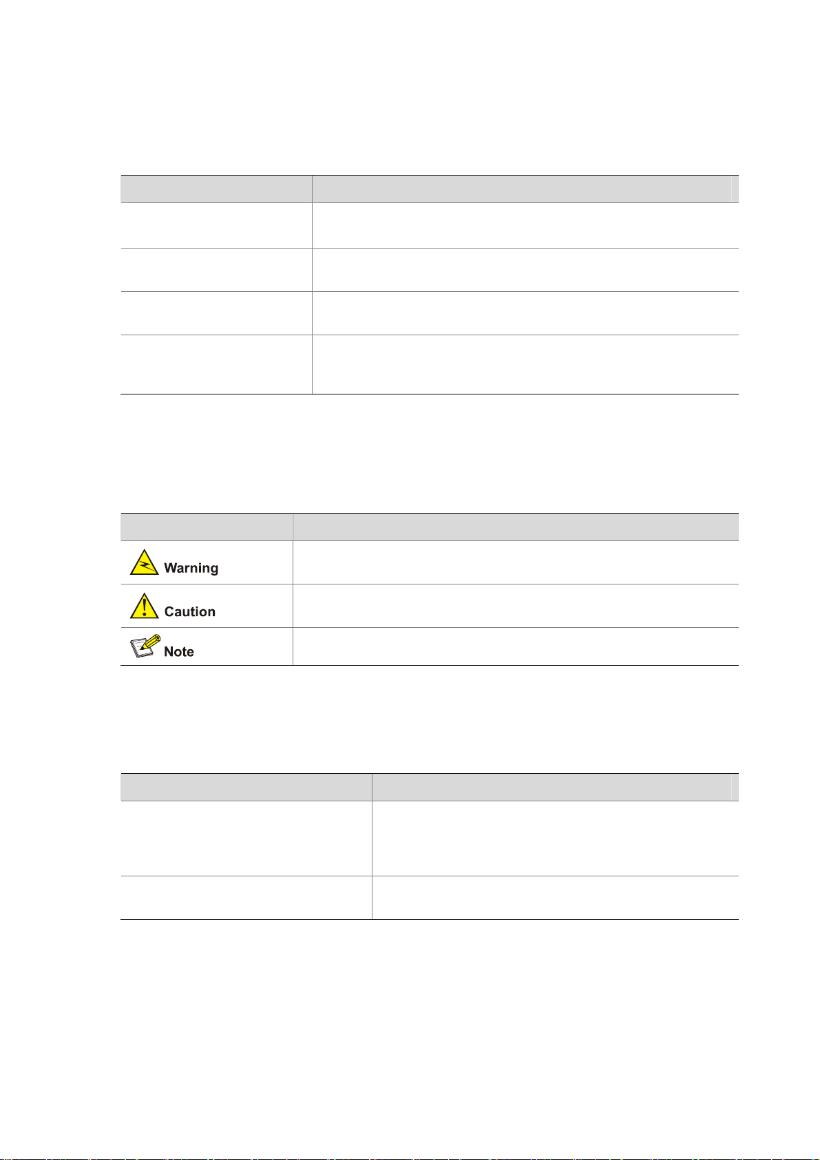
Figure 1-1 shows the typical deployment of the WA2200 series on hotspots.
Figure 1-1 Deployment of the WA2200 series on hotspots (Fat AP mode)
PC
PC
PC
PC
WA2200
WA2200
WA2200
WA2200
Auditorium
Switch
Restaurant or
tea house
Switch
Parking lot
Switch
Hall or information
desk
Switch
Core equipment
room
Switch
Radius server
Wireless
NMS
Service
database server
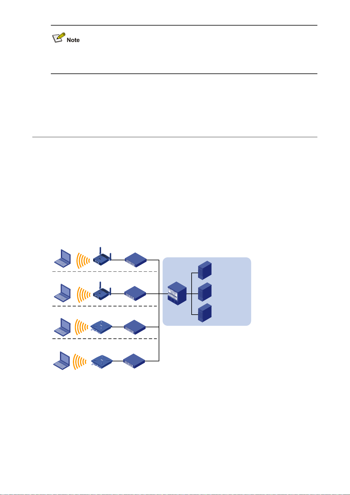
Figure 1-2 shows the appearance of the WA2200 series.
1-1
Page 8
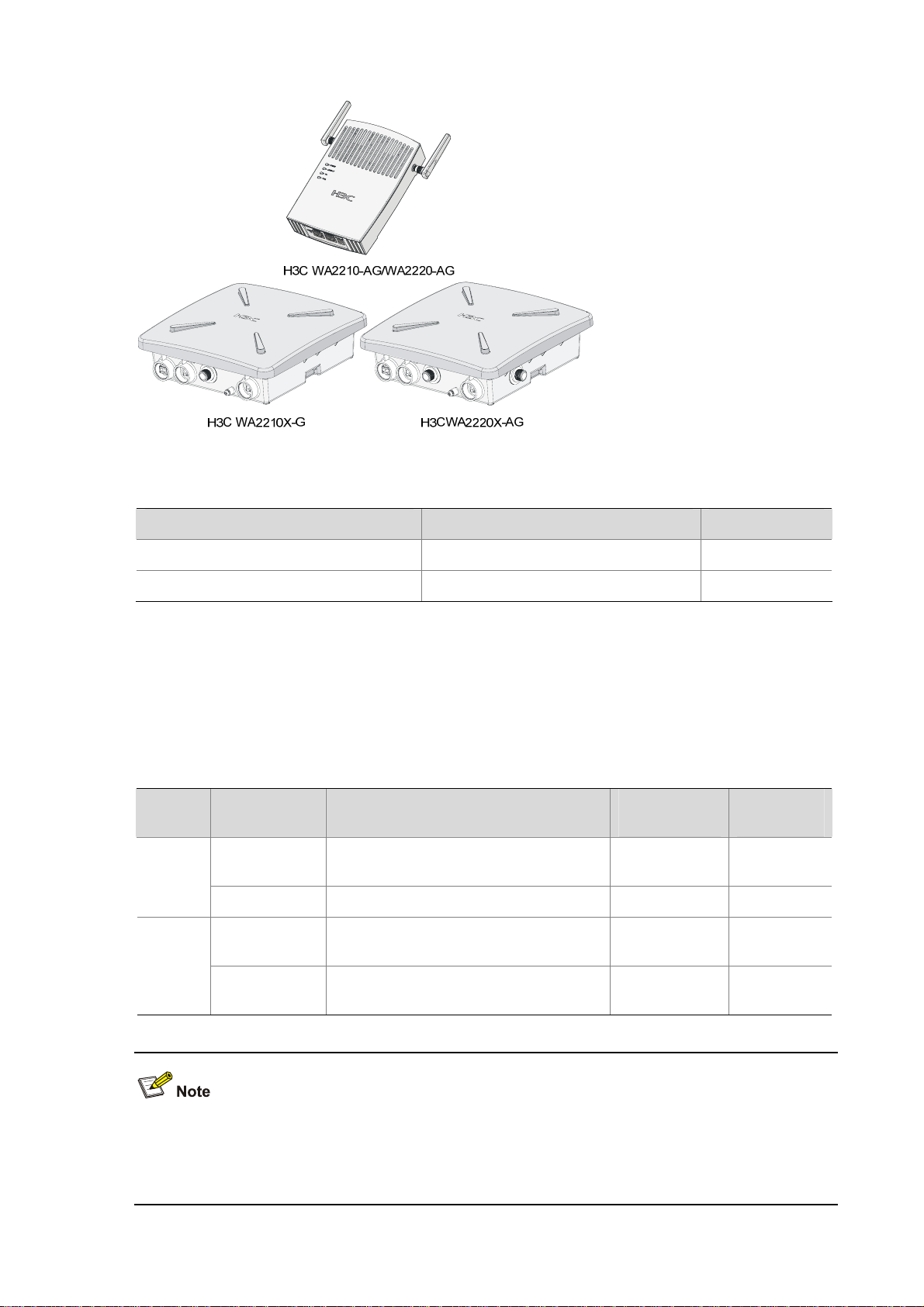
Figure 1-2 Appearance of the WA2200 series
Table 1-1 Physical dimensions of the WA2200 series
Model Physical dimensions (H×W×D) Weight
WA2210-AG/WA2220-AG, (indoor) 40×166×118 mm (1.57×6.54×4.65 in.) 0.5 kg (1.10 lb)
WA2210X-G/WA2220X-AG, (outdoor) 76×245×245 mm (2.99×9.65×9.65 in.) 2 kg (4.41 lb)
Hardware Configuration
The four models of the WA2200 series have different radio frequencies (RFs) and structures. Table 1-2
lists the protocols that each model supports as well as the chassis materials.
Table 1-2 Protocols that each model supports and the chassis material
Type Model Protocols and chassis material
IEEE802.11a or IEEE802.11b/g,
plastic
IEEE802.11b/g, waterproof cast
aluminum + plastic
IEEE802.11a + IEEE802.11b/g,
waterproof cast aluminum + plastic
Indoor
Outdoor
WA2210-AG
WA2220-AG IEEE802.11a + IEEE802.11b/g, plastic 10 W Yes
WA2210X-G
WA2220X-AG
Power
consumption
8 W Yes
8 W Yes
10 W No
802.3af PoE
support
An outdoor AP will start the internal over-cold protection function in case of a temperature lower than
–15°C, and the power consumption will increase 3 W to 5 W. In this case, you need to use an external
PoE module to supply power to the AP.
1-2
Page 9
The WA2200 series have extraordinary radio frequency (RF) performance and provide consummate
service functions. With IP66 degree of protection, the outdoor models can be directly deployed outdoors
to simplify the installation. The models of the WA2200 series are designed for application in various
environments.
This section describes the hardware configurations and functions of the WA2200 series in detail.
LEDs
The positions and identifications of LEDs on the panel vary with the models. For details about these
LEDs, see
WA2210-AG/WA2220-AG
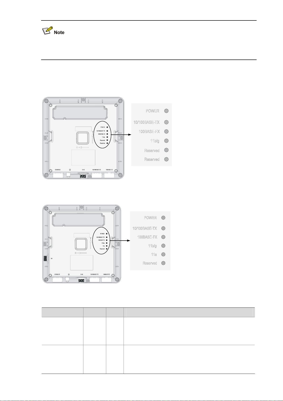
Figure 1-3 LEDs on the WA2210-AG/WA2220-AG
Table 1-3 and Table 1-4.
Table 1-3 Description of LEDs on the WA2210-AG/WA2220-AG
LED Color QTY Meaning
Displays the power supply status:
POWER Green
1
z On: The power supply is normal.
z Off/flashing: The power supply is not connected or well
connected, or works abnormally.
Displays the link status of the Ethernet interface:
LINK/ACT Green
1
z On: The link on the Ethernet interface is up.
z Off: The link on the Ethernet interface is down.
z Flashing: Data is being transmitted or received.
Displays the wireless link status:
11a Green
1
z Off: The wireless link is not initialized or the link is faulty.
z Flashing slowly: The wireless link is normal.
z Flashing quickly: Data is being transmitted or received.
Displays the wireless link status:
11b/g
Green
1
z Off: The wireless link is not initialized or the link is faulty.
z Flashing slowly: The wireless link is normal.
z Flashing quickly: Data is being transmitted or received.
1-3
Page 10
The WA2210-AG is a single-RF device. The 11a and 11b/g LEDs cannot be on or flash at the same
time.
WA2210X-G/WA2220X-AG
Figure 1-4 LEDs on the WA2210X-G
Figure 1-5 LEDs on the WA2220X-AG
Table 1-4 Description of LEDs on the WA2210X-G/WA2220X-AG
LED Color QTY Meaning
POWER Green
10/100BASE-TX Green
Displays the power supply status:
1
z On: The power supply is normal..
z Off/flashing: The power supply is not connected or well
connected or the device works abnormally.
Displays the status of the Ethernet interface:
1
z On: The link on the Ethernet interface is up.
z Off: The link on the Ethernet interface is down.
z Flashing: Data is being transmitted or received.
1-4
Page 11
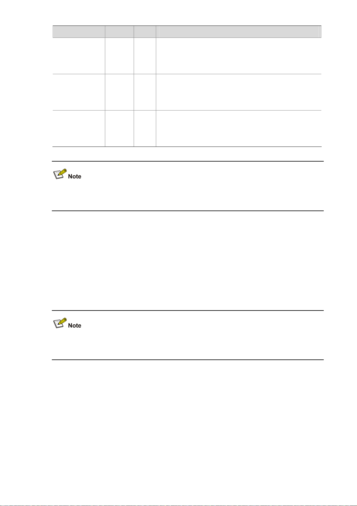
LED Color QTY Meaning
Displays the status of the optical interface:
100BASE-FX
Yellow 1
z On: The link on the optical interface is up.
z Off: The link on the optical interface is down.
z Flashing: Data is being transmitted or received.
Displays the wireless link status:
11a Green
1
z Off: The wireless link is not initialized or the link is faulty.
z Flashing slowly: The wireless link is normal.
z Flashing quickly: Data is being transmitted or received.
Displays the wireless link status:
11b/g Green
1
z Off: The wireless link is not initialized or the link is faulty.
z Flashing slowly: The wireless link is normal.
z Flashing quickly: Data is being transmitted or received.
z The WA2210X-G is a single-RF device and has no 11a LED.
z The word “reserved” means the LED is reserved for future use.
Interfaces
The interfaces provided by the WA2200 series include:
z 2.4 GHz or/and 5 GHz antenna interface(s)
z Console interface
z Ethernet interface (optical and electrical)
z Power interface for indoor models
In addition, a reset button (indoor and enhanced models), a security slot (indoor and enhanced models),
and a grounding screw (outdoor models) are provided.
Table 1-5 describes the interfaces provided by each model.
1-5
Page 12

Table 1-5 Descriptions of interfaces on WA2200 series WLAN access points
Model Interface
Antenna
interface 1
Console
interface
WA2210-AG/
WA2220-AG
Ethernet
interface
Power interface N/A
Antenna
interface 2
Ethernet optical
interface
Standards and
protocols
Description
WA2210-AG: Main antenna interface,
IEEE802.11b/g
RS/EIA-232
IEEE802.3
IEEE802.3u
IEEE802.3af
2.4/5-GHz
WA2220-AG: 2.4-GHz antenna interface
The console interface is used for device
configuration and management.
The Ethernet interface can serve as an
uplink interface of the device to access the
Internet or a MAN, and can simultaneously
serve as a PoE interface.
The power interface is used for +48 VDC
power supply to the device.
WA2210-AG: Auxiliary antenna interface,
IEEE802.11a
2.4/5-GHz
WA2220-AG: 5-GHz antenna interface
The Ethernet optical interface can serve as
IEEE802.3
SFP MSA
SFF-8472
an uplink interface to access the Internet or
a MAN. The Ethernet optical interface is
used to connect an SFP module. In practice,
either the Ethernet electrical interface or the
Ethernet optical interface is used.
WA2210X-G/
WA2220X-AG
Ethernet
electrical
interface
Antenna
interface 1
Console
interface
Antenna
interface 2
IEEE802.3
IEEE802.3u
IEEE802.3af
IEEE802.11b/g
RS/EIA-232
IEEE802.11a
The Ethernet electrical interface can serve
as an uplink interface of the device to
access the Internet or a MAN, and can
simultaneously serve as a PoE interface.
This antenna interface is used to connect a
2.4-GHz antenna or a feeder.
The console interface is used for device
configuration and management.
This antenna interface is used to connect a
5-GHz antenna or a feeder.
1-6
Page 13
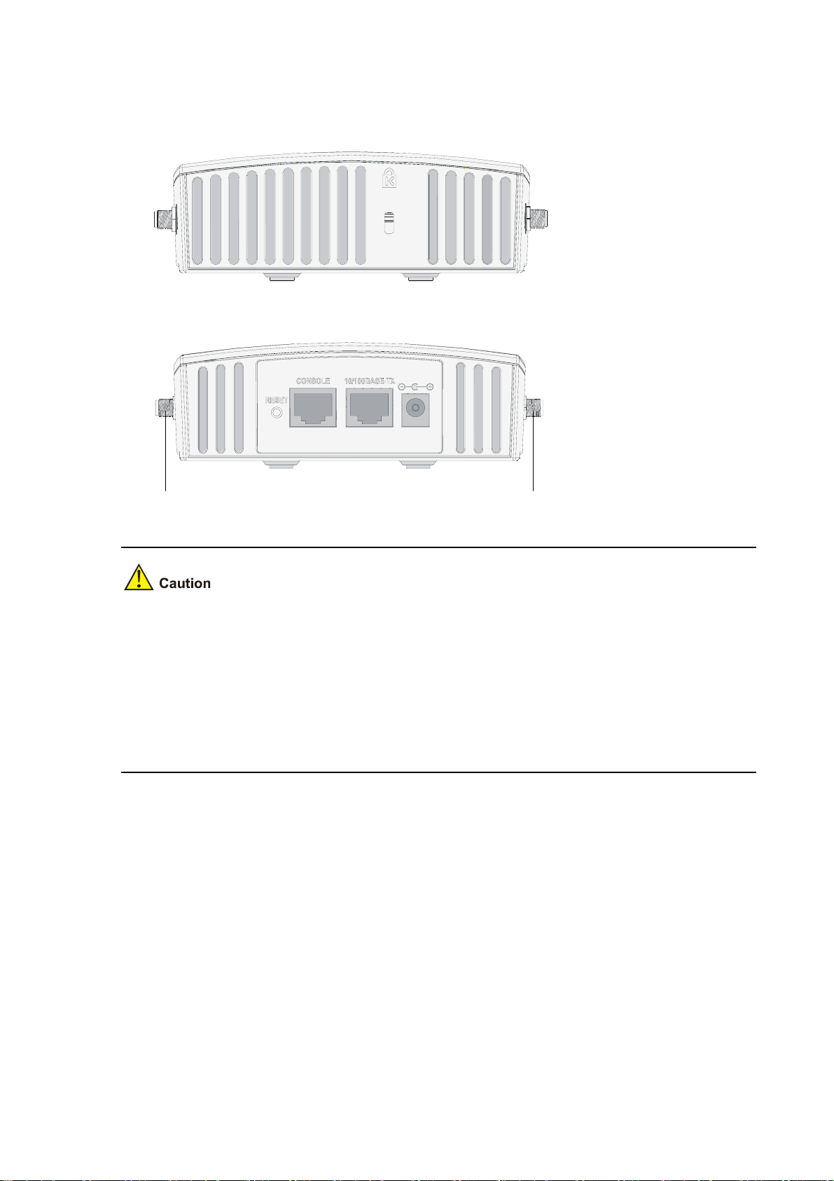
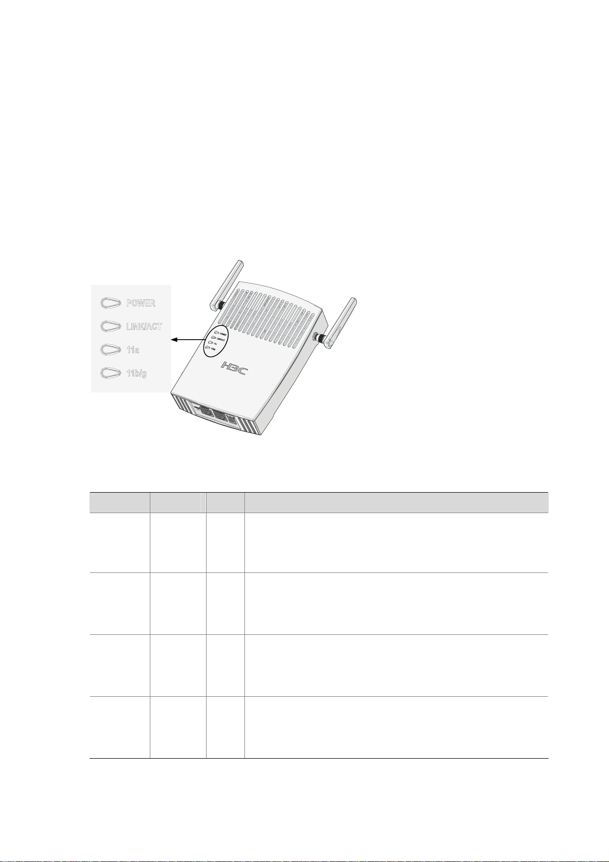
Interfaces provided by WA2210-AG/WA2220-AG
Figure 1-6 Interfaces on WA2210-AG/WA2220-AG
Top view
Bottom view
Antenna interface 1
Antenna interface 2
z WA2210-AG is a single-RF device. Viewed from the front, the antenna interface on the left
(antenna interface 1 in
(antenna interface 2 in
Figure 1-6) is the main antenna interface, while the one on the right
Figure 1-6) is the auxiliary antenna interface. When there is only one
antenna, the antenna must be installed on the main antenna interface.
z WA2220-AG is a dual-RF device. Viewed from the front, the antenna interface on the left (antenna
interface 1 in
interface 2 in
Figure 1-6) is the 2.4-GHz antenna interface, while the one on the right (antenna
Figure 1-6) is the 5-GHz antenna interface.
1-7
Page 14
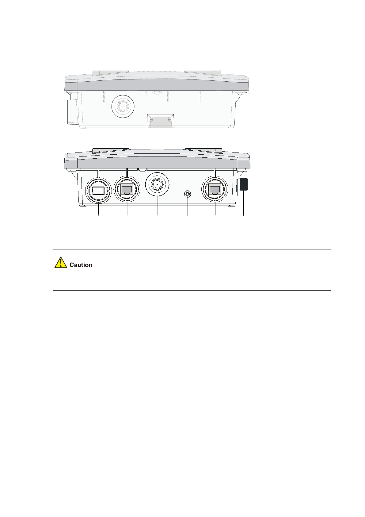
Interfaces provided by WA2210X-G/WA2220X-AG
Figure 1-7 Interfaces on WA2210X-G/WA2220X-AG
Right view(WA2220X-AG)
Bottom view(WA2210X-G/WA2220X-AG)
100BASE-FX
10/100BASE-TX
Antenna
interface1
Grounding
screw
Consol
interface
Antenna
interface2
WA2210X-G is a single-RF device and provides no 5-GHz antenna interface.
1-8
Page 15

2 Installation Preparations
This chapter describes the preparations for WA2200 installation, including preparation of installation
tools, environment examination, and unpacking & inspection.
Safety Precautions
Installation and removal of the unit and its accessories must be carried out by qualified personnel. You
must read all of the Safety Instructions supplied with your device before installation and operation.
Installation und Ausbau der Anlage und ihrer Zubehörteile müssen von qualifiziertem Personal realisiert
werden. Sie müssen vor der Installation oder Bedienung allen beiliegenden Sicherheitshinweise lesen.
负责安装和日常维护本设备的人员必须具备安全操作基本技能。在操作本设备前,请务必认真阅读和执
行产品手册规定的安全规范。
Preparing Installation Tools
When installing the AP, you may need the tools listed in Table 2-1. You should select the appropriate
tools according to the installation environment.
Table 2-1 List of installation tools
Type of tool Indoor installation Outdoor installation
1-meter-long ruler, marking pen, knife, and
General tools
Special tools
Auxiliary tools Ladder and rubber hammer
percussion drill with matching drills
Cable stripper, crimping pliers, and RJ-45
crimping pliers
2-1
Digging tool, adjustable spanner, and
vices
Cable stripper, crimping pliers, RJ-45
crimping pliers, waterproof tape, and
fiber fusion splicer
Ladder
Page 16

Table 2-1 is only for reference. If you install the AP on a desk, none of the above tools is required; if you
install the AP on top of or under eave of a building, no digging tool is required.
Examining the Installation Site
Before installation, you should examine the installation site to keep the AP under a good operational
environment. You can examine the installation site from the following two aspects:
Installation Site Selection
Keep the AP away from places that are susceptible to high temperature, dust, inflammable, explosive,
electromagnetic interference (high power radar, radio station, and transformer), unstable voltage, heavy
vibration, or loud noise. The installation site should be dry, without any leakage, dripping, or dew .The
AP should be at least 500 m (0.31 mi) away from the seaside and should not face the direction of sea
wind.
In engineering design, the site should be selected according to the network planning and technical
requirements of communications equipment, as well as the considerations such as climate, hydrology,
geology, earthquake, electric power, and transportation.
Temperature and Humidity Requirements
Table 2-2 lists the operating temperature and humidity requirements.
Table 2-2 Environment specifications
Specification Range
Operating temperature (indoor)
Operating temperature (outdoor)
Storage temperature (indoor)
Storage temperature (outdoor) –40°C to +85°C (–40°F to +185°F)
Operating humidity (noncondensing)
Power Supply
-10°C to 55°C (14°F to 131°F)
–40°C to +65°C (–40°F to +149°F)
–40°C to +70°C (–40°F to +158°F)
5% to 95%
The WA2200 series can be powered through 802.3af-compliant power over Ethernet (PoE) (except
WA2220X-AG) or an external power adaptor. For details see the
Outside China it is recommended that this unit be PoE powered. Please see the H3C/3Com product
catalogues for a range of 802.3af compatible power sources.
2-2
Table 2-3.
Page 17

Table 2-3 Power Supply
Power Source Connection Details Ordering information
H3C WA2200 series access
AC/DC Power Adapter
points can accept power from
an AC/DC power adapter. Input
specification is as follows:
+48V
, 0.52A min.
Connect the adapter’s power
If you need an AC/DC power
adapter for your H3C WA2200
series access point, you must
use the FSP025-1AD207A
adapter(part number
0231A0EQ) which is available
from H3C/3Com.
jack to the AP power interface.
H3C WA2200 series access
points (except WA2220X-AG)
Power over Ethernet (PoE,
IEEE 802.3af standard) power
source
can accept power from a PoE
power source.
No DC power adapter is
required. Connect the PoE
Please see the H3C/3Com
product catalogues for a range
of 802.3af compatible power
sources.
cable directly to the 10/100
Base-TX Ethernet connector.
Grounding and Lightning Protection
Table 2-4 Grounding and lightning protection requirements
SN Item Requirements
z The earth resistance is usually required to be less than 5 ohms, and less
than 10 ohms in an area with less than 20 thunderstorm days a year. If a
piece of angle steel is buried as the earthing conductor, the earth resistance
is required to be less than 10 ohms. In an area with a higher earth resistance,
reduce the earth resistance by using brine or resistance reducing agent
around the earthing conductor.
z The top of the earthing conductor should be at least 0.7 m (2.30 ft) away from
the ground surface. In cold areas, the earthing conductor should be buried
below the frozen soil layer.
z If a grounding strip is available, connect the yellow and green ground cable
of the AP to the grounding strip. If you need to make a grounding cable, the
cable should be with a cross-section area of at least 6 mm
length of no longer than 3 m (9.84 ft).
z If no grounding strip is available, bury a piece of angle steel/steel tube at
least 0.5 m (1.64 ft) long in the earth to serve as the earthing conductor. In
the case of a piece of angle steel, the size should be at least 50 mm × 50 mm
× 5 mm (1.97 in. × 1.97 in. × 0.20 in.); in the case of a piece of steel tube, it
must be zinc-plated and have a wall thickness of at least 3.5 mm (0.14 in.).
Weld the yellow and green ground cable of the AP onto the earthing
conductor and use anti-erosion treatment on the welding joint. The
grounding cable should be as short as possible and must not be coiled.
z Ensure that the grounding points of all the lightning arresters of the AP and
the peer device of the AP are well grounded.
1
2
Grounding
resistance
Device
protection
ground
(PGND)
2
(0.24 in2) and a
3
Grounding
lead-in
A grounding lead-in is a metal conductor connecting a grounding net and a
grounding strip. The grounding cable of the AP should be connected to the
grounding strip. The grounding lead-in must be 30 m (98.43 ft) or shorter. A
piece of zinc-coated flat steel with a cross-section area of 40 × 4 mm (1.57 ×
0.16 in) or 50 × 5 mm (1.97 × 0.20 in) is recommended. Connect the grounding
strip and the grounding lead-in of the AP through the yellow and green ground
cable with an area of 35 mm
treatment on the welding joint.
2
(1.38 in.), or weld them directly. Use anti-erosion
2-3
Page 18

SN Item Requirements
Power
4
grounding
(AC)
5
Lightning
arrester
6 Feeder
Outdoor
7
lightning
arrester
8
Network
cable
z Use a power cord with a protective earth (PE). Do not use a power cord with
only an L line and an N line.
z The neutral line of the power cord should not be connected with the PGND of
other communications equipment. The L and N lines cannot be connected
In plain areas, the protection angle of the lightning rod should be less than 45
degrees. In mountainous areas or lightning areas, the protection angle should
be less than 30 degrees. The lightning protection grounding (for example, the
grounding of the lightning rod) should be connected to the earthing conductor of
the equipment room.
z The antenna support is already prepared according to the design
requirements.
z A feeder lightning rod is already installed and grounded according to the
design requirements.
Power lightning arrester, port lightning protector, and feeder lightning arrester
are recommended for outdoor installations. The power lightning arrester and the
feeder lightning arrester should be near the AP, and the network interface
lightning arrester should be near the peer device of the AP. The network
interface lightning arrester should be installed where the network cable is just
led out of the room.
Use a shielded twisted pair cables for an AP used outdoors. Ensure that the
devices at the two ends of the cable are well grounded.
After you have completed the preparations, you can start installing the AP. The installation of indoor
models is different from that of the outdoor models. For details, refer to
3-1 and 4 “Installation of Outdoor APs” on page 4-1.
page
3 “Installation of Indoor APs” on
2-4
Page 19

3 Installation of Indoor APs
You can directly place an indoor model (including the enhanced model) on a desk. The rubber feet on
the bottom of the AP help you to place it horizontally. Or you can fix it onto a wall by using the
wall-mounting bracket. The following introduces the wall-mounting procedure of the indoor models and
enhanced model in detail.
Installation Flowchart
Figure 3-1 shows the installation flowchart of the indoor models and enhanced model.
Figure 3-1 Installation flowchart of an indoor AP
Start
Determine the
installation position
Install the AP
Connect the power
supply and network
End
Determining the Installation Position
Determine the installation position by observing the following principles:
z Leave as few obstacles (such as wall and ceiling) as possible between the AP and stations.
z Keep the AP far away from electronic devices (such as microwave oven) that may generate RF
noise.
z Install the AP in a place where it will not hinder people’s daily work and life.
z Do not install the AP in a place where water seeping, water soaking, and condensing occur.
Prevent water or moisture from entering the AP.
Ensure the intensity and structure of the ceiling meet the requirements for ceiling mounting of the AP.
You are recommended to reinforce the ceiling using boards if it is not strong enough. A padlock is
required to prevent any falloff in case of shocks.
3-1
Page 20

Installing the AP
The following describes how to install the AP on a wall.
z Installing the Wall-Mounting Bracket on a Wall
z Installing the AP on the Wall-Mounting Bracket
z Locking the AP onto the Wall-Mounting Bracket (Optional)
Installing the Wall-Mounting Bracket on a Wall
Follow these steps to install the wall-mounting bracket on a wall:
Step1 Drill holes 6 mm (0.24 in) in diameter on the wall where the AP should be mounted. The drilled holes
should correspond to those in the wall-mounting bracket. There are eight installation holes in total in the
wall-mounting bracket. You should select at least four holes for installation.
Figure 3-2 Screw hole locations and screw hole size (in mm)
49.0
44.6
22.3
49.1
150.0
49.1
75.0
62.9
104.0
Step2 Insert the pointed end of anchors into the drilled holes and tap the flat end of anchors with a rubber
hammer until they are all flush with the wall surface.
Step3 Align the holes in the wall-mounting bracket with the anchors and insert screws through the installation
holes into the anchors, as shown in
Figure 3-3.
Step4 Adjust the position of the wall-mounting bracket and tighten the screws.
3-2
Page 21

Figure 3-3 Install the wall-mounting bracket
When installing the wall-mounting bracket, position it so that the arrowhead points upward.
Installing the AP on the Wall-Mounting Bracket
Follow these steps to install the AP on the wall-mounting bracket:
Step1 Align the AP with the hooks on the wall-mounting bracket and hang the AP on the bracket (see (1) in
Figure 3-4).
Step2 Then press the AP downward to fix it (see (2) in
Figure 3-4).
3-3
Page 22

Figure 3-4 Fix the indoor AP onto the wall-mounting bracket
Expansion screw
Hock
(1)
(2)
Locking the AP onto the Wall-Mounting Bracket (Optional)
The indoor APs have a security slot on the top, which can be used to lock the AP onto the wall-mounting
bracket to prevent theft.
Follow these steps to lock the AP onto the wall-mounting bracket:
Step1 Insert the locking plate into the security slot on the top of the AP (see (1) in
Figure 3-5).
Step2 Turn the locking plate counterclockwise until the hole on the locking plate is aligned with the hole in the
wall-mounting bracket (see (2) in
Step3 Put the latch through the two holes that are aligned in step 2 (see (3) in
Figure 3-5).
Figure 3-5).
Step4 Lock the latch with a lock.
3-4
Page 23

Figure 3-5 Lock the indoor AP onto the wall-mounting bracket
The lock is user supplied.
Connecting the Power Supply
Local Power Supply
Connect the AP to the power adapter and then to the power source, as shown in Figure 3-6.
3-5
Page 24

Figure 3-6 Local power supply connection
Power interface
Power adapter
Power over Ethernet
If the uplink device of the AP is a PoE switch or the like, use an Ethernet cable to directly connect the
Ethernet interface of the AP to the PoE device.
Figure 3-7 PoE connection
z In the case of PoE, you do not need to connect the power interface to a power source. You only
need to connect one end of an Ethernet cable to the Ethernet interface of the AP and the other end
to an Ethernet interface of a PoE switch (for example, Ethernet switch).
z Identify the silkscreen on the device to avoid taking the console interface for the Ethernet interface
and vice versa.
Connecting the Network
Connect the Ethernet interface of the AP to an Ethernet interface of the switch to implement Internet or
MAN access, as shown in
Figure 3-8.
3-6
Page 25

Figure 3-8 Connect the AP to the network
Wireless station
Internet
Wired station
WA2200
Wired station
Switch
3-7
Page 26

4 Installation of Outdoor APs
The outdoor models of the WA2200 series are H3C WA2210X-G and H3C WA2220X-AG. You can
select an appropriate model according to the actual requirement. The two outdoor models are
waterproof, dustproof, and lightningproof.
Installation Flowchart
You can install your outdoor AP on a wall or a pole. As a wireless device, the installation location directly
affects the coverage and performance of wireless signals. Therefore, it is recommended that the AP be
installed by a professional.
Figure 4-1 Installation flowchart of the outdoor models
Figure 4-1 shows the installation flowchart of the outdoor models.
Start
Install the wall-mounting
bracket
wall-mounting bracket or the
Install the fixing support
on the pole
Fix the AP onto the
mounting plate
Install the outdoor
antenna
Install the RF
cable
Install the Ethernet
cable/fiber cable
Connect the power
cable (optional)
Connect the
power supply
End
Installing the AP
The following describes how to install the AP on a wall and a pole respectively.
Installing the AP on a wall
Figure 4-2 illustrates the installation flowchart of the AP on a wall.
4-1
Page 27

Figure 4-2 Installation flowchart of the AP on a wall
Start
Mark
Drill holes
Install anchors
Fix the wall-mounting bracket
Fix the AP
End
1) Mark
Step Operation
1 Put the wall-mounting bracket on the installation position against the wall.
2
Mark three expansion screw holes on the wall. For the distance (in mm) between the
expansion screw holes, see
Figure 4-3.
The wall-mounting bracket is not supplied unless ordered.
4-2
Page 28

Figure 4-3 Wall-mounting bracket structure and positions of screw holes
195.0
135.0
80.0
40.070.0
220.0
2) Drill holes
Step Operation
1 Use a percussion drill with a 6-mm (0.24-in) bit to drill holes on the three markings.
Observe the following precautions when drilling:
z Hold the drill handle with both hands, with the bit perpendicular to the wall surface, and prevent wall
damage or tilted holes.
z The hole depth should be the anchor length plus the bit length. Each hole should have the same
depth. Remove the dust from the hole before measuring the hole depth. Use a vacuum cleaner to
prevent dust from spreading around.
z If the wall surface is too solid and slippery to locate the bit, punch a notch first.
3) Install anchors
Before installation, remove dust inside and around all holes with a vacuum cleaner, and then measure
the distances between holes. If there is a large error, mark and drill holes again.
4-3
Page 29

Step Operation
1 Put an anchor into each hole vertically.
2
Tap the flat end of the anchor with a rubber hammer until the anchor is flush with the wall
surface.
4) Fix the wall-mounting bracket
Step Operation
1
Align the three holes in the wall-mounting bracket with the anchors and insert three
expansion screws through the installation holes into the anchors.
2 Adjust the position of the wall-mounting bracket and tighten the expansion screws.
5) Fix the AP
Step Operation
Method 1: Align the two installation holes in the AP with the corresponding holes in the
1
2
wall-mounting bracket and then use two screws to fix them.
Method 2: Insert a screw into each installation hole in the AP, but do not tighten them. Then
insert the screws into the corresponding holes in the wall-mounting bracket.
Tighten the screws so that the AP touches against the wall-mounting bracket, as shown in
Figure 4-4.
Figure 4-4 Install the outdoor AP on a wall
Screw M6×12
Installing the AP on a pole
The fixing support for installing the outdoor AP on a pole consists of two major components: a pair of
V-shaped brackets and a mounting plate. The outdoor AP can be fixed on a vertical or horizontal pole
4-4
Page 30

with an outer diameter of 60 to 110 mm (2.36 to 4.33 in) through the fixing support. The mounting plate
and the V-shaped bracket are fixed through the self-clinching bolt and a nut, as shown in
Figure 4-5.
Figure 4-5 Mounting plate and V-shaped bracket
You can adjust the angle of the AP as needed. Follow these steps to adjust the angle of the AP:
Step1 Follow the arrowhead shown in
Figure 4-6 to turn the V-shaped bracket with the self-clinching bolt as
the pivot to adjust the angle of the mounting plate.
Step2 Use tie-bar bolts through the guide slots and nuts (see
bracket.
Figure 4-6 Adjust the angle of the AP
Figure 4-8) to fix the mounting plat and V-shape
On the top of a building, the outdoor AP is usually installed on a pole.
Follow these steps to install the outdoor AP on a pole:
Step3 As shown in
Figure 4-7, fix the pole base onto the top surface of a building or onto a cement pier.
4-5
Page 31

Figure 4-7 Pole and pole base
Step4 Fix the mounting plate onto one V-shaped fixing bracket with a self-clinching bolt.
Step5 Fix the pair of V-shaped fixing brackets on a vertical or horizontal pole with tie-bar bolts, flat washers,
spring washers, and nuts (see
Figure 4-8 or Figure 4-9).
Figure 4-8 Install the outdoor AP on a vertical pole
4-6
Page 32

Figure 4-9 Install the outdoor AP on a horizontal pole
Step6 Fix the AP onto the mounting plate with screws (see the dashed line and arrow in
4-9).
You can first install the fixing support onto the pole and then the AP onto the mounting plate, or vice
versa.
Installing an Outdoor Antenna
There are two types of outdoor antennas: directional antenna and omni antenna. An omni antenna can
be directly installed on an outdoor AP.
Installing a directional outdoor antenna on a pole
Figure 4-8 or Figure
You should select such an installation location for the pole that the antenna direction and tilt could be
adjusted freely.
4-7
Page 33

Follow these steps to install a pole on a parapet:
Step1 Weld the lightning rod onto the tip of the pole.
Step2 Install the pole on a parapet or cement pier.
Step3 Use a 40 × 4 mm (1.57 × 0.16 in) flat steel to connect the pole to the ground grid
Step4 Use pole-mounting brackets to install the directional outdoor antenna on the pole.
The pole should be vertical to the building top surface, as shown in
Figure 4-10 and Figure 4-11.
Figure 4-10 Install a directional outdoor antenna on a parapet
Figure 4-11 Install a directional outdoor antenna on a building top surface or cement pier
Lightning rod
Pole-mounting brackets
Directional
outdoor antenna
Antenna support
(antenna pole)
Steel wire
Cement pier
Flat steel
To the grounding grid
Φ75mm
500mm
1500mm
z If there are parapets around the building top and the parapets are 1200 mm (47.24 in) high or
higher, install the antenna pole on a parapet with expansion bolts and fix the directional outdoor
antenna onto the pole with pole-mounting brackets (see the left diagram in
Figure 4-10).
4-8
Page 34

z If there are parapets around the building top and the parapet height is less than 1200 mm (47.24 in),
fix one point of the pole to the parapet with one expansion bolt and the other point to the building
top surface with another expansion bolt, and fix the directional outdoor antenna onto the pole with
pole-mounting brackets (see the right diagram in
z If there is no parapet around the building top, first use expansion bolts to secure the pole vertically
on the building top surface or cement pier, and then use pole-mounting brackets to fix the
directional outdoor antenna onto the pole, as shown in
Installing an omni outdoor antenna on a pole
When installing an omni outdoor antenna on a pole, observe the following precautions:
z The pole should be 35 to 50 mm (1.38 to 1.97 in) in diameter. Usually, a round steel with a diameter
of 50 mm (1.97 in) is adopted.
z The top of the pole should be flush with the upper clamp, as shown in Figure 4-12.
z The antenna height should meet the signal coverage requirement and the tip of the antenna should
fall within the 45° protection angle of the lightning rod.
Usually, no lightning rod is directly soldered onto an omni antenna pole (no metal object is allowed
within one meter in the horizontal direction of the omni antenna). Instead, a lightning rod is set on a
separate pole between two omni antenna poles and the lightning rod is high enough to keep the tip of
omni antennas within the protection angle.
Figure 4-10).
Figure 4-11.
Figure 4-12 Install omni antennas
45°
Lightning
protection angle
45°
Lightning rod
Omni outdoor
antenna
Clamp
Antenna pole
If the lightning rod cannot be installed on a separate pole owing to the environment limitation, the
installation method shown in
Figure 4-13 can be adopted. In this case, the lightning rod pole should be
at least one meter away from the omni antenna pole.
4-9
Page 35

Figure 4-13 Install an omni antenna under a special environment
Lightning rod
45°
Omni outdoor
antenna
>1000mm
Clamp
Angle steel
Antenna ploe
In Figure 4-13, the antenna pole is welded with two angle steels to the lightning rod pole, instead of a
cement pier.
Installing an omni antenna on the AP directly
A low-gain omni rod antenna can be directly installed on the AP. The installation procedure is as follows:
Step1 Screw a feeder lightning arrester onto the downward 2.4-GHz antenna interface.
Step2 Screw one end the plug-to-plug adaptor onto the feeder lightning arrester.
Step3 Screw the omni rod antenna onto the other end of the plug-to-plug adaptor.
Step4 Ground the feeder lightning arrester with a grounding cable. (See
Figure 4-14)
Step5 Ground the AP with a grounding cable.
4-10
Page 36

Figure 4-14 Install an omni antenna on the AP directly
z After the omni antenna is installed on the AP, the antenna should be at least one meter away from
the pole or other metal objects.
z The outdoor AP and the feeder lightning arrester are each equipped with a 3-meter-long grounding
cable. If the length is not long enough, you need to supply longer grounding cables. For the
grounding requirements, refer to section “
Connecting External Cables
z Before connecting external cables, check that all power lines are disconnected, and that there is no
dangerous voltage on the neutral (N) line.
z Protect the AP and cables against water and avoid external cable damage.
Grounding and Lightning Protection” on page 2-3.
External cables to be connected include an RF cable, Ethernet cable, fiber cable, grounding cable, and
power cord.
Connecting the RF cable
The RF cable refers to the cable between the antenna interface and the antenna. Follow these steps to
connect the RF cable:
Step1 Screw one end of the feeder lightning arrester onto the antenna interface.
4-11
Page 37

Step2 Connect one end of the RF cable to the feeder lightning arrester and the other end to the outdoor
antenna.
Step3 Wrap each joint with insulation tape first, and then with waterproof tape.
z It is recommended to install a feeder lightning arrester on each antenna interface and ground it
well.
z A finished RF cable with a fixed length can be shipped with the AP if ordered. If such an RF cable is
not long enough, you should provide a longer RF cable and an N-type RF connector and prepare
the cable at the site.
z Distinguish the stickiness of the two sides of waterproof tape. Before wrapping a cable joint, stretch
the waterproof tape so that the width is three quarters of the original one to ensure the tightness.
Connecting an Ethernet cable
Follow the steps below to connect an Ethernet cable. Otherwise, the AP may get damaged
Step1 As shown in
equipment room to the AP installation location.
Figure 4-15 Connect the Ethernet electrical interface to the uplink device
Indoor
LAN switch
Figure 4-15, Figure 4-16 and Figure 4-17, route the waterproof Ethernet cable from the
Outdoor
Antenna
RF coaxial
AP
Ethernet Cable
AC
power
Port lightning protector
Grounding cable
Power adaptor
4-12
Page 38

Figure 4-16 Connect the Ethernet optical interface to the uplink device
Figure 4-17 Exploded view of the port lightning protector (PoE)
z If the uplink device is a PoE switch, no port lightning protector or power adapter is required. It is not
recommended to provide power to the AP using a PoE switch.
z If the Ethernet optical interface serves as an uplink data interface, the Ethernet electrical interface
only serves as a PoE interface.
z There are two Ethernet interfaces on the power injector, as shown in Figure 4-17. Ensure that the
Ethernet interface on the surge side is connected to the AP.
z Whether the AP is powered by a PoE switch or the power injector, ensure that the AP has been
installed as required before power-on.
Step2 Prepare an Ethernet cable connector
4-13
Page 39

Since an Ethernet cable needs to pass through a waterproof cover for waterproof purpose (an Ethernet
cable with an RJ-45 connector is unable to pass through), you need to prepare an Ethernet cable
connector on site. Usually a category-5 or enhanced category-5 twisted pair cable is adopted.
Figure
4-18 shows an Ethernet cable connector.
Figure 4-18 Ethernet cable connector
Ethernet cables fall into straight-through Ethernet cables and crossover Ethernet cables.
z Straight-through Ethernet cable: The wires of a twisted pair cable are crimped in the same
sequence in the RJ-45 connectors at both ends. A straight-through cable is used to connect a
terminal device (such as PC or router) to a hub or LAN Switch.
z Crossover Ethernet cable: The wires of a twisted pair cable are crimped in different sequences in
the RJ-45 connectors at both ends. A crossover Ethernet cable is used to connect a terminal
device (such as PC or router) to another terminal device. You can make such a cable by yourself.
Table 4-1 RJ-45 straight-through Ethernet cable pinouts
Pin of RJ-45
connector
Signal
1 Tx+ White (orange)
2 Tx- Orange
3 Rx+ White (green)
4 — Blue
5 — White (blue)
Category-5 twisted pair
cable
Signal direction
Æ
Æ
Å
Pin of RJ-45
connector
1
2
3
— 4
— 5
6 Rx- Green
7 — White (brown)
8 — Brown
Table 4-2 RJ-45 crossover Ethernet cable pinouts
Pin of RJ-45
connector
Signal
1 Tx+ White (orange)
2 Tx- Orange
Category-5 twisted pair
cable
4-14
Å
6
— 7
— 8
Signal direction
Æ
Æ
Pin of RJ-45
connector
3
6
Page 40

Pin of RJ-45
connector
Signal
3 Rx+ White (green)
4 — Blue
5 — White (blue)
6 Rx- Green
7 — White (brown)
8 — Brown
Category-5 twisted pair
cable
Signal direction
Å
Pin of RJ-45
connector
1
— 4
— 5
Å
2
— 7
— 8
z When distinguishing or preparing these two types of Ethernet cables, you can refer to the above
tables. Since the Ethernet interface of the AP is auto-sensing, these two types of Ethernet cables
can be used for the Ethernet interface.
z Refer to Table 4-1 and Table 4-2 to arrange the wire sequence when preparing an Ethernet cable.
Otherwise, the communication quality will not be high, even if the devices at both ends can
communicate.
z The Ethernet cable should be equipped with a waterproof sheath when routed outdoors. If possible,
cable routing in waterproof tubes is recommended.
Step3 Insert the Ethernet cable connector into the Ethernet interface, as shown in
Figure 4-19 Insert the Ethernet cable connector into the Ethernet interface
Figure 4-19.
Step4 First tighten the waterproof cover and then the sealing nut.
Step5 Use waterproof tape to wrap the joint between the waterproof cover and the cable.
4-15
Page 41

Connecting an optical fiber
Be sure to follow the instructions below when connecting a fiber cable. Otherwise, the AP may get
damaged.
When connecting the AP to the remote device through a fiber cable, use an appropriate SFP module.
The SFP modules provided by H3C can be used outdoor. These SFP modules use single-mode optic
fibers and have a transmission distance of 15 km (9.32 miles).
You need to configure an SFP module and a waterproof cover when connecting the AP to an uplink
device through a fiber cable, as shown in
Figure 4-20 Connect a fiber cable
Figure 4-20.
Follow these steps to connect a fiber cable:
Step1 Insert an SFP module into the Ethernet optical interface on the AP.
Step2 Insert the LC connectors with a waterproof cover into the two optical interfaces on the SFP module.
Step3 First tighten the waterproof cover and then the sealing nut.
Step4 Use waterproof tape to wrap the joint between the waterproof cover and the fiber cable.
4-16
Page 42

The fiber cable is a 10-meter tail fiber with a waterproof cover. One end of the fiber is an LC connector
with a waterproof joint, and the other end is an SC connector, which can be connected to a fiber or
device. For users using an optical cable terminal box, you can insert the SC connector of the tail fiber to
the SC socket on the optical cable terminal box. The mark A on the SC socket is the RX end of the AP,
which should be connected to the TX end of the peer device, and the mark B is the TX end of the AP,
which should be connected to the RX end of the peer device. Optical cable terminal boxes are not
waterproof, and therefore should be installed indoors or in a waterproof chassis. For users using an
optical cable splice closure, you need to cut off the SC connector, and then wrap the fiber. Note that the
A and B marks correspond to the RX and TX ends of the AP respectively and should be connected to
the TX and RX ends of the peer device respectively when you wrap the fiber. Optical cable splice
closures are waterproof and can be buried or installed overhead.
Connecting the power cable
The WA2210X-G and WA2220X-AG AP support external PoE power supply.
z To use a PoE switch to supply power to the AP, connect the port of the switch to the
10/100BASE-TX port of the AP through an Ethernet cable.
z To supply power through a port lightning protector, connect the devices as shown in Figure 4-21.
Figure 4-21 Exploded view of the port lightning protector (PoE)
To switch
Protect port
48 VDC
port
Connect to AC power (220V)
Power adapter
To AP
Surge
PE
Step1 Insert the plug of the power adapter into the 48 VDC port of the POE-MH port lightning protector.
Step2 Connect the port of the switch to the protect port of the POE-MH port lightning protector using an
Ethernet cable.
Step3 Connect the grounding cable to the PE port of the POE-MH port lightning protector, tighten it, and make
sure that the grounding cable is well grounded.
Step4 Connect the surge port of the POE-MH port lightning protector to the 10/100BASE-TX port of the AP
using an Ethernet cable.
4-17
Page 43

z If a PoE switch is used to supply power, no port lightning protector or power adapter is required. It
is not recommended to provide power to the AP using a PoE switch over a long distance.
z To supply power to the AP through a port lightning protector, you need to connect the port lightning
protector to the switch. The switch does not need to be a PoE switch and you need to use a power
adapter to provide power to the remote AP.
z No matter whether the AP is powered by a PoE switch or by a power adapter through a port
lightning protector, ensure that the AP is installed correctly before power-on.
Powering On the AP
After all cables are correctly connected as shown in Figure 4-22, power on the AP and check the status
of the LEDs. For the description of the LED status, refer to section “
LEDs” on page 1-3.
4-18
Page 44

Figure 4-22 Connection of external cables of the AP
Outdoor antenna
Connecting the Network
In practice, the AP can be connected to the Internet or a MAN through an Ethernet interface, as shown
Figure 4-23.
in
RF cable
Outdoor antenna
Grounding cable for
feeder lightning arrester
Grounding cable
Ethernet cable
Fiber cable
4-19
Page 45

Figure 4-23 Connection between the AP and Internet (the AP works in the FAT AP mode)
A special outdoor waterproof Ethernet cable is required to connect the AP and waterproof treatment
should be made to the Ethernet cable at the outlet of the chassis.
4-20
 Loading...