

Page 1

SuperStack® II Switch
®
Management Guide
For units in the SuperStack II Switch 1100/3300 and 610/630 Family
Management Software Version 2.50
http://www.3com.com/
Part No. DUA1695-0BAA04
Published May 2000
Page 2

3Com Corporation
5400 Bayfront Plaza
Santa Clara, California
95052-8145
Copyright © 2000, 3Com Technologies. All rights reserved. No part of this documentation may be reproduced
in any form or by any means or used to make any derivative work (such as translation, transformation, or
adaptation) without written permission from 3Com Technologies.
3Com Technologies reserves the right to revise this documentation and to make changes in content from time
to time without obligation on the part of 3Com Technologies to provide notification of such revision or
change.
3Com Technologies provides this documentation without warranty, term, or condition of any kind, either
implied or expressed, including, but not limited to, the implied warranties, terms or conditions of
merchantability, satisfactory quality, and fitness for a particular purpose. 3Com may make improvements or
changes in the product(s) and/or the program(s) described in this documentation at any time.
If there is any software on removable media described in this documentation, it is furnished under a license
agreement included with the product as a separate document, in the hard copy documentation, or on the
removable media in a directory file named LICENSE.TXT or !LICENSE.TXT. If you are unable to locate a copy,
please contact 3Com and a copy will be provided to you.
UNITED STATES GOVERNMENT LEGEND
If you are a United States government agency, then this documentation and the software described herein are
provided to you subject to the following:
All technical data and computer software are commercial in nature and developed solely at private expense.
Software is delivered as “Commercial Computer Software” as defined in DFARS 252.227-7014 (June 1995) or
as a “commercial item” as defined in FAR 2.101(a) and as such is provided with only such rights as are
provided in 3Com’s standard commercial license for the Software. Technical data is provided with limited rights
only as provided in DFAR 252.227-7015 (Nov 1995) or FAR 52.227-14 (June 1987), whichever is applicable.
You agree not to remove or deface any portion of any legend provided on any licensed program or
documentation contained in, or delivered to you in conjunction with, this User Guide.
Unless otherwise indicated, 3Com registered trademarks are registered in the United States and may or may not
be registered in other countries.
3Com, the 3Com logo, Net Age, SmartAgent, SuperStack and Transcend are registered trademarks of
3Com Corporation. CoreBuilder and PACE are trademarks of 3Com Corporation. 3ComFacts is a service mark
of 3Com Corporation.
All other company and product names may be trademarks of the respective companies with which they are
associated.
ENVIRONMENTAL STATEMENTS
It is the policy of 3Com Corporation to be environmentally- friendly in all operations. To uphold our policy, we
are committed to:
• Establishing environmental performance standards that comply with national legislation and regulations.
• Conserving energy, materials and natural resources in all operations.
• Reducing the waste generated by all operations. Ensuring that all waste conforms to recognized
environmental standards. Maximizing the recyclable and reusable content of all products.
• Ensuring that all products can be recycled, reused and disposed of safely.
• Ensuring that all products are labelled according to recognized environmental standards.
• Improving our environmental record on a continual basis.
End Of Life Statement
3Com processes allow for the recovery, reclamation and safe disposal of all end- of- life electronic
components.
Regulated Materials Statement
3Com products do not contain any hazardous or ozone- depleting material.
Environmental Statement about the Documentation
The documentation for this product is printed on paper that comes from sustainable, managed forests; it is
fully biodegradable and recyclable, and is completely chlorine- free.
The varnish is environmentally-friendly, and the inks are vegetable-based with a low heavy-metal content.
Page 3

C
ONTENTS
BOUT THIS GUIDE
A
Conventions 13
Related Documentation 15
Year 2000 Compliance 15
Documentation Comments 16
Product Registration 16
I Getting Started with Management
UPERSTACK
1
S
What is Management Software? 20
Summary of Software Features 20
Software Features Explained 21
Stack Management 21
Forwarding Modes 21
Duplex Modes 22
Flow Control 23
Traffic Prioritization 23
PACE 24
Security 24
Resilient Links 25
Port Trunks 25
Broadcast Storm Control 26
Virtual LANs 26
FastIP 26
Multicast Filtering 27
Spanning Tree Protocol 27
RMON 27
Roving Analysis 28
Management 28
Default Settings 29
WITCH MANAGEMENT SOFTWARE
II S
Page 4

2
ETTING UP FOR MANAGEMENT
S
Methods of Managing a Switch 32
Setting Up Web Interface Management 33
Setting Up Through the Console Port 33
Setting Up Over the Network 34
Installing Online Help and Documentation 34
Choosing a Browser 35
Configuring the Browser 35
Setting Up Command Line Interface Management 36
Setting Up Through the Console Port 36
Setting Up Over the Network 37
Setting Up SNMP Management 37
Managing a Switch Over the Network 38
IP Addresses 38
Obtaining a Registered IP Address 38
Subnets and Using a Subnet Mask 39
Logging in as a Default User 39
II The Management Interfaces
3
ORKING WITH THE WEB INTERFACE
W
Accessing the Web Interface 44
Exiting the Web Interface 45
The Getting Started Pages 46
The Main Web Interface 48
The External Link Icons 49
The Management Icons 50
The Page Area 50
Navigating the Page Area 52
Making Changes in the Page Area 53
Configuring the Current Switch 54
Displaying the Status of the Ports 54
Displaying the Color Codes Used by the Switch Graphic 54
Displaying the Speed and Duplex Mode of Ports 55
Refreshing the Switch Graphic 55
Displaying Administration Details 56
Page 5

Setting Up IP Information 58
Configuring a Port 59
Configuring the Console Port 66
Changing the Management Settings for the Stack 67
Specifying a Descriptive Name 67
Changing Your Password 68
Specifying a Physical Location 69
Accessing the Getting Started Pages 69
Specifying the Location of the Online Help and Documentation 70
Specifying Contact Details 71
Configuring the Stack 71
Configuring the Switch Database 72
What is the Switch Database? 72
Displaying the Switch Database 73
Inserting Permanent Entries 74
Deleting Entries 75
Configuring the Advanced Stack Settings 76
Setting Up Resilient Links 79
What are Resilient Links? 79
Displaying Resilient Link Pairs 80
Creating a Resilient Link Pair 80
Deleting a Resilient Link Pair 81
Swapping the Active Port of a Resilient Link Pair 81
Setting Up Port Trunks 81
What are Port Trunks? 82
Displaying the Ports that Belong to Each Port Trunk 82
Placing Ports in a Port Trunk 82
Configuring VLANs 83
What are VLANs? 84
Defining VLAN Information 84
Editing VLAN Information 84
Deleting VLAN Information 85
Displaying the Ports that Belong to Each VLAN 85
Placing Ports in Single VLANs 85
Placing Ports in Multiple VLANs Using VLT Tagging 85
Placing Ports in Multiple VLANs Using 802.1Q Tagging 85
Setting Up Roving Analysis Ports 86
What is Roving Analysis? 87
Page 6

Defining Monitor Ports and Analysis Ports 87
Enabling the Roving Analysis System 88
Resetting All the Units in the Stack 88
What Happens During a Reset? 88
Initializing All the Units in the Stack 88
What Happens During an Initialization? 88
Upgrading Management Software 89
Displaying Statistics for the Current Switch 91
Displaying Unit Statistics 91
Interpreting the Statistics 92
Displaying Port Statistics 92
Interpreting the Statistics 94
4
ORKING WITH THE COMMAND LINE INTERFACE
W
Accessing the Interface 96
Exiting the Interface 96
How Many Users Can Access the Interface? 97
About the Interface Menus 97
Entering Commands 99
Displaying Menus 100
Obtaining Help 100
A Quick Guide to the Commands 101
Displaying and Changing Bridging/VLANs Information 105
Setting the Bridge Address Aging Time 105
Displaying Bridge Information 105
Enabling and Disabling IGMP Snooping 107
Enabling and Disabling Router Port Auto-Discovery 108
Manually Identifying a Router Port 108
Displaying all Router Ports 108
Removing a Router Port 109
Adding a Statically Configured Address to a Switch Database 110
Finding a MAC Address 110
Displaying MAC Addresses for a Port 111
Removing MAC Addresses from a Port 111
Displaying Port Information 111
Setting the Spanning Tree Path Cost 112
Enabling and Disabling Spanning Tree Fast Start 112
Page 7

Displaying Port Summary Information 113
Enabling and Disabling VLT Tagging on a Port 114
Setting the Bridge Spanning Tree Forward Delay 114
Setting the Bridge Spanning Tree Hello Timer 115
Setting the Bridge Spanning Tree Maximum Age 115
Setting the Spanning Tree Bridge Priority 115
Enabling and Disabling Spanning Tree on a Bridge 116
Adding a Port to a VLAN 116
Creating a VLAN 116
Deleting a VLAN 117
Displaying Detailed VLAN Information 117
Modifying a VLAN 118
Removing a Port from a VLAN 119
Displaying Summary VLAN Information 119
Displaying and Changing Port Information 120
Enabling and Disabling Ports 120
Specifying the Speed and Duplex Mode 121
Enabling and Disabling Auto-negotiation 121
Enabling and Disabling Flow Control 123
Displaying Port Statistics 123
Packet Size Analysis 126
Displaying Port Summary Information 126
Displaying and Changing System Feature Information 127
Setting up a Roving Analysis Port 127
Displaying the Roving Analysis Port Information 127
Removing a Roving Analysis Port 128
Starting Data Monitoring 128
Stopping Data Monitoring 129
Enabling and Disabling Broadcast Storm Control 129
Setting Up a Resilient Link 130
Displaying Resilient Link Information 130
Removing a Resilient Link 131
Swapping over Active Links 131
Adding a Port to a Trunk 131
Displaying Detailed Trunk Information 132
Removing a Port from a Trunk 132
Displaying Summary Trunk Information 133
Displaying and Changing IP-related Information 133
Page 8

Specifying IP and SLIP Information 133
Displaying IP and SLIP Information 135
Enabling and Disabling BOOTP 135
Pinging Other Devices 136
Resetting the IP Configuration 136
Displaying and Changing SNMP-related Information 137
Specifying SNMP Community Strings 137
Specifying Trap Destination Details 137
Displaying Trap Destination Details 138
Modifying Trap Destination Details 138
Removing Trap Destination Details 139
Performing an SNMP GET Command 139
Performing an SNMP GETNEXT Command 139
Performing an SNMP SET Command 140
Displaying and Changing Stack Information 141
Moving the Focus of the Command Line Interface 141
Returning the Focus to the Previous Switch Unit 142
Specifying Stack Administration Details 142
Displaying Switch Administration Details 143
Displaying Stack Summary Information 144
Configuring Intelligent Modules 146
Setting Module Configuration 146
Displaying Module Configuration 146
Enabling and Disabling the Module Interface 146
Changing Your Password 147
Specifying User Details 147
Displaying User Details 148
Modifying User Details 148
Removing User Details 149
Displaying Access Rights 149
Modifying Access Rights 150
Enabling and Disabling Remote Access 150
Resetting All the Units in the Stack 151
What Happens During a Reset? 151
Initializing All the Units in the Stack 152
What Happens During an Initialization? 152
Upgrading Management Software 153
Page 9

III Management Reference
ORT TRUNKS
5
P
What are Port Trunks? 158
Port Trunks and Your Switch 158
Placing Ports in a Port Trunk 159
Port Trunk Example 160
6
IRTUAL
V
What are VLANs? 164
Benefits of VLANs 164
VLANs and Your Switch 165
VLAN Configuration for Beginners 171
VLAN Configuration - Advanced Examples 177
LANS (VLANS)
The Default VLAN 165
Defining New VLANs 166
Untagged and Tagged VLANs 166
Placing a Port in a Single VLAN 166
Placing a Port in Multiple VLANs 166
802.1Q Tagging 166
VLT Tagging 167
Using IEEE 802.1Q Learning 167
Forwarding Traffic Containing Unknown 802.1Q Tags 168
Connecting VLANs to Other VLANs 170
Connecting to VLANs on Legacy Switch Units 170
Simple Example: Using Untagged Connections 171
Simple Example: Untagged Connections with Hubs 172
Simple Example: 802.1Q Tagged Connections 174
Using 802.1Q Tagged Connections and 802.1Q Learning 177
Connecting to a Legacy Network 178
AST
7
F
IP
What is FastIP? 182
How FastIP Works 182
An Example 183
FastIP and the Switch Database 186
Enabling FastIP 187
Page 10

8
9
ULTICAST FILTERING
M
What is a Multicast? 190
What is Multicast Filtering? 190
Multicast Filtering and Your Switch 191
IEEE 802.1p Multicast Filtering 191
Enabling 802.1p Multicast Learning 191
IGMP Multicast Filtering 192
Enabling IGMP Multicast Learning 192
Manual Filtering 192
PANNING TREE PROTOCOL
S
What is STP? 194
How STP Works 196
STP Requirements 196
STP Calculation 197
STP Configuration 197
STP Reconfiguration 197
An Example 198
STP Configurations 199
Using STP on a Network with Multiple VLANs 201
Connecting to STP Systems on Legacy Switch Units 202
Enabling STP 202
10
RMON
What is RMON? 204
The RMON Groups 204
Statistics 204
History 204
Alarms 204
Hosts 205
Hosts Top N 205
Matrix 205
Events 205
Benefits of RMON 206
RMON and Your Switch 207
The Alarm Events 208
The Default Alarm Settings 208
The Audit Log 209
Page 11

IV Problem Solving
11
ROBLEM SOLVING
P
Solving Web Interface Problems 214
Solving Command Line Interface Problems 216
Solving SNMP Management Software Problems 218
Solving Serial Web Utility Problems 219
Solving Management Software Upgrade Utility Problems 220
Solving Other Problems 221
V Appendices and Index
A
B
ERIAL WEB UTILITY
S
Introduction 227
Installing the Serial Web Utility 227
Using the Serial Web Utility 229
ANAGEMENT SOFTWARE UPGRADE UTILITY
M
Using the Upgrade Utility 231
LOSSARY
G
NDEX
I
Page 12

Page 13
A
BOUT
T
HIS
G
UIDE
Conventions
This guide provides all the information you need to manage units in the
SuperStack
software version 2.50.
The guide is intended for use by network administrators who are
responsible for installing and setting up network equipment;
consequently, it assumes a basic working knowledge of LANs (Local Area
Networks).
Throughout this guide, the term stack refers to a number of Switch units
that are managed as a single unit. However, a stack can contain a single
Switch. In the case of the 610/630 family, stackability is not supported.
If the information in the release notes that are shipped with your product
differs from the information in this guide, follow the instructions in the
release notes.
Ta bl e 1 and Tabl e 2 list conventions that are used throughout this guide.
Tab le 1
Icon Notice Type Description
®
II Switch 1100/3300 and 610/630 family with management
Notice Icons
Information note Information that describes important features or
instructions
Caution Information that alerts you to potential loss of data or
Warning Information that alerts you to potential personal injury
potential damage to an application, system, or device
Page 14

14 A
BOUT THIS GUIDE
Tab le 2
Text Conventions
Convention Description
Screen displays
This typeface represents information as it appears on the
screen.
Syntax
The word “syntax” means that you must evaluate the syntax
provided and then supply the appropriate values for the
placeholders that appear in angle brackets. Example:
To change your password, use the following syntax:
system password <password>
In this example, you must supply a password for
.
Commands
<password>
The word “command” means that you must enter the
command exactly as shown and then press Return or Enter.
Commands appear in bold. Example:
To display port information, enter the following
command:
bridge port detail
The words “enter”
and “type”
When you see the word “enter” in this guide, you must type
something, and then press Return or Enter. Do not press
Return or Enter when an instruction simply says “type.”
Keyboard key names If you must press two or more keys simultaneously, the key
names are linked with a plus sign (+). Example:
Press Ctrl+Alt+Del
Words in italics Italics are used to:
■
Emphasize a point.
■
Denote a new term at the place where it is defined in the
text.
■
Identify menu names, menu commands, and software
button names. Examples:
From the Help menu, select Contents.
Click OK.
Page 15

Related Documentation 15
Related Documentation
In addition to this guide, each document set in the Switch 1100/3300
and 610/630 family includes the following:
■
User Guide
This guide contains all the hardware and installation information for
the Switch.
■
Quick Reference Guide
This guide contains a quick summary of the hardware and software
information for the Switch
■
Quick Installation Guide
This guide contains a summary of the package contents, and a quick
summary of the installation information for the Switch.
■
Release Notes
These notes provide information about the current software release,
including new features, modifications, and known problems.
■
SuperStack II Switch Help
This help provides information about the web interface software of
the Switch. It is supplied on the SuperStack II Switch Family CD-ROM.
■
SuperStack II Switch README File
This file provides information about the current software release,
including new features, modifications, and known problems.
Year 2000 Compliance
In addition, there are other publications you may find useful:
■
Documentation accompanying the Expansion Modules.
■
Documentation accompanying the Transceiver Modules.
■
Documentation accompanying the Advanced Redundant Power
System.
For information on Year 2000 compliance and 3Com products, visit the
3Com Year 2000 Web page:
http://www.3com.com/products/yr2000.html
Page 16

16 A
BOUT THIS GUIDE
Documentation Comments
Product Registration
Your suggestions are very important to us. They will help make our
documentation more useful to you. Please e-mail comments about this
document to 3Com at:
pddtechpubs_comments@3com.com
Please include the following information when commenting:
■
Document title
■
Document part number (on the title page)
■
Page number (if appropriate)
Example:
■
SuperStack II Switch Management Guide
■
Part Number DUA1695-0BAA04
■
Page 21
You can now register your SuperStack II Switch on the 3Com web site to
receive up-to-date information on your product:
http://www.3com.com/productreg/pdd
Page 17

I
G
ETTING
M
ANAGEMENT
Chapter 1 SuperStack II Switch Management Software
Chapter 2 Setting Up for Management
S
TARTED WITH
Page 18

Page 19

S
UPERSTACK
II S
WITCH
1
M
ANAGEMENT
This chapter contains introductory information about the SuperStack® II
Switch management software and how it can be used in your network. It
covers the following topics:
■
What is Management Software?
■
Summary of Software Features
■
Software Features Explained
■
Default Settings
S
OFTWARE
Page 20

20 C
HAPTER
1: S
UPERSTACK
II S
WITCH MANAGEMENT SOFTWARE
What is Management Software?
Summary of Software Features
Your Switch contains software that allows you to change and monitor the
way it works. This
management
software is not required to get the
Switch working, but if you do use it, you may improve the efficiency of
the Switch and therefore improve the overall performance of your
network.
Ta bl e 3 describes the software features that are supported by units in the
Switch 1100/3300 and 610/630 family.
Tab le 3
Feature Switch 1100/610 Family Switch 3300 /630 Family
No. of MAC
Addresses
Supported
Stack
Management
Forwarding
Modes
Duplex Modes
Flow Control
Tra ffic
Prioritization
PACE
Security
Resilient Links
Port Trunking
Broadcast Storm
Control
Virtual LANs
(VLANs)
FastIP
Multicast Filtering
Software features
Up to 6,000 Up to 12,000
Supported for up to four
Switch units (stackability not
supported on 610/630 units)
Store and Forward, Fast
Forward, Fragment Free,
Intelligent
Half and full duplex on all
ports
Supported on all ports Supported on all ports
Supported Supported
Supported on all ports Supported on all ports
Supported on all ports Supported on all ports
Supported Supported
Support for two Port Trunks a
unit
Supported Supported
Support for up to 16 VLANs
using the IEEE 802.1Q
standard
Supported Supported
IEEE 802.1p and IGMP
filtering supported
Supported for up to four
Switch units (stackability not
supported on 610/630 units)
Store and forward
Half and full duplex on all
ports
Support for two Port Trunks a
unit
Support for up to 16 VLANs
using the IEEE 802.1Q
standard
IEEE 802.1p and IGMP
filtering supported
Page 21

Software Features Explained 21
Software Features Explained
Stack Management
Tab le 3
Feature Switch 1100/610 Family Switch 3300 /630 Family
Spanning Tree
Protocol
RMON
Roving Analysis
Management
Software features
Supported Supported
Seven groups supported:
Statistics, History, Alarms,
Hosts, Hosts Top N, Matrix,
Events
Supported Supported
Web interface, command line
interface, and SNMP
supported
Seven groups supported:
Statistics, History, Alarms,
Hosts, Hosts Top N, Matrix,
Events
Web interface, command line
interface, and SNMP
supported
Units in the Switch 1100/3300 family can be interconnected so that they
form a stack, that is, a group of devices that are managed as a single
device.
Stackability is not supported by the Switch 610/630 units.
Forwarding Modes
You can interconnect these Switch units together in two ways:
■
The matrix port on the rear of each Switch allows you to connect two
Switch units back-to-back. For this you need a Matrix Cable (part
number 3C16965).
■
The Expansion Module slot at the rear of each Switch allows you to
install a Matrix Module (part number 3C16960). The Matrix Module
provides four ports and allows you to interconnect up to four units
using Matrix Cables.
For information about stacking Switch units, refer to Chapter 2 of the
relevant Switch User Guide.
Units in the Switch 3300/630 family support Store and Forward packet
forwarding mode. In this mode, received packets are buffered entirely
before they are forwarded, which ensures that only good packets are
forwarded to their destination.
Page 22

22 C
HAPTER
1: S
UPERSTACK
II S
WITCH MANAGEMENT SOFTWARE
Units in the Switch 1100/610 family support three forwarding modes in
addition to Store and Forward:
■
Fast Forward
— Packets are forwarded as soon as the destination
address is received and processed. With Fast Forward, packets take
less time to be forwarded, but all error packets are propagated onto
the network because no time is allowed for checking.
■
Fragment Free
— Packets are forwarded when at least 512 bits of the
packet is received, which ensures that collision fragments are not
propagated through the network. With Fragment Free, packets take
less time to be forwarded, but all error packets except fragments are
propagated.
■
Intelligent
— The Switch monitors the amount of error traffic on the
network and changes the forwarding mode accordingly. If the Switch
detects less than 20 errors a second, the forwarding mode is set to
Fast Forward. If the Switch detects 20 or more errors a second, the
forwarding mode is set to Store and Forward until the number of
errors a second returns to zero.
For information about setting the forwarding mode for units in the
Switch 1100/610 family, see
on
page 76
.
“Configuring the Advanced Stack Settings”
Duplex Modes
All the ports on your Switch can be set to one of two duplex modes:
■
Half duplex
— Allows packets to be transmitted and received, but not
simultaneously. This is the default Ethernet duplex mode.
■
Full duplex
— Allows packets to be transmitted and received
simultaneously and, in effect, doubles the potential throughput of a
link. In addition, full duplex supports 100BASE-FX cable runs of up to
2km (6562ft).
To communicate effectively, both ends of a link must use the same duplex
mode. If the link uses an auto-negotiating connection, this is done
automatically. If the link uses a connection that is not auto-negotiating,
both ends must be set to half duplex or full duplex manually.
For more information about setting the duplex mode of a port, see
“Configuring a Port”
on
page 59
.
Page 23

Software Features Explained 23
Flow Control
Traffic Prioritization
All the ports on your Switch support flow control, which is a congestion
control mechanism. Congestion is caused by one or more devices sending
traffic to an already overloaded port on the Switch. Flow control prevents
packet loss and inhibits the devices from generating more packets until
the period of congestion ends.
Flow control is implemented in two ways:
■
IEEE 802.3x standard for ports operating in full duplex.
■
Intelligent Flow Management (IFM), a 3Com proprietary method of
flow control, for ports operating in half duplex. IFM should only be
enabled if the port is connected to another switch, or an endstation. If
the port is connected to a repeated segment with local traffic, IFM
should be disabled.
For information about enabling flow control on a port, see
a Port”
on
page 59
.
“Configuring
Your Switch supports IEEE 802.1p traffic prioritization, which allows data
that has been assigned a high priority to be forwarded through the
Switch without being obstructed by other data. The system works by
using the multiple traffic queues that are present in the hardware of the
Switch — high priority traffic is forwarded on a different queue from
other traffic, and it is always given preference over the other traffic.
Traffic prioritization can be useful for critical applications that require a
high Class of Service (CoS) from the network. This could include:
■
Financial applications
— Accounts departments that need
immediate access to large files and spreadsheets at the end of the
month.
■
CAD/CAM design applications
— Design departments that need
priority connections to server farms and other devices for transferring
large files.
■
Converged network applications
— Organizations with a
converged network (that is, a network that uses the same
infrastructure for voice data and traditional data) that require high
quality voice data transmission at all times.
Page 24

24 C
HAPTER
1: S
UPERSTACK
II S
WITCH MANAGEMENT SOFTWARE
If you use IEEE 802.1p traffic prioritization, we recommend that all
relevant ports on your Switch are placed in one or more Virtual LANs
(VLANs) using 802.1Q tagging. For a brief explanation of VLANs, see
on
“Virtual LANs”
page 26
802.1Q tagging, see
. For a detailed explanation of VLANs and
“Virtual LANs (VLANs)”
on
page 163
.
PACE
Security
Your Switch supports PACE (Priority Access Control Enabled) which is a
3Com proprietary feature that allows multimedia traffic to move across a
network effectively.
PACE provides two main features:
■
Implicit Class of Service
— This feature gives priority to traffic from
multimedia applications, and provides the same functionality as IEEE
802.1p traffic prioritization (see “Traffic Prioritization”
■
Interactive Access
— When two-way multimedia traffic passes over
on page 23).
an Ethernet or Fast Ethernet network, interference can occur because
access to the bandwidth is unequally allocated to traffic in one
direction. The Interactive Access feature allocates the available
bandwidth equally in both directions, therefore increasing the quality
of the multimedia traffic.
For information about enabling PACE on an individual port, see
on
“Configuring a Port”
page 59
on a whole Switch or stack, see
Settings”
on
page 76
.
. For information about enabling PACE
“Configuring the Advanced Stack
Each port on your Switch can use a security feature that guards against
unauthorized users connecting devices to your network. When security is
enabled on a port, it enters Single Address Learning Mode. In this mode,
the Switch:
■
Removes all the MAC (Ethernet) addresses stored for the port in the
Switch Database. For more information about the Switch Database,
see “What is the Switch Database?”
■
Learns the address of the first packet it receives on the port.
■
Defines the address as a permanent entry.
on page 72.
Once the first address is learned:
■
The port is disabled if a different address is seen on the port.
Page 25

Software Features Explained 25
■
No other address can be learned until security is disabled or the
address is manually removed from the database.
■
The address cannot be learned on another port until security is
disabled or the address is manually removed from the database.
Resilient Links
Port Trunks
For more information about enabling security on a port, see
a Port”
on
page 59
.
“Configuring
The resilient link feature of the Switch enables you to protect critical links
and prevent network downtime should those links fail. Setting up
resilience ensures that if a main communication link fails, a standby
duplicate link immediately and automatically takes over the task of the
main link. Each main and standby link pair is referred to as a resilient link
pair.
Resilient links are a simple method of creating redundancy that provides
you with an instant reaction to link failure. Resilient links are quick to set
up, you have full control over their configuration, and the port at the
other end of the resilient link does not have to support any resilience
feature.
For more information about resilient links, see
Links”
on
page 79
.
“Setting Up Resilient
Your Switch supports port trunks — connections that allow devices to
communicate using up to four links in parallel. Port trunks provide two
benefits:
■
They can potentially double, triple or quadruple the bandwidth of a
connection.
■
They can provide redundancy — if one link is broken, the other links
share the traffic for that link.
For more information about port trunks, see
“Port Trunks”
on
page 157
.
Page 26

26 C
HAPTER
1: S
UPERSTACK
II S
WITCH MANAGEMENT SOFTWARE
Broadcast Storm
Control
Virtual LANs
Your Switch supports Broadcast Storm Control, a system that
automatically creates an alarm for each port to monitor the level of
broadcast traffic on that port.
frames per
broadcast
second, the broadcast traffic on the port is blocked until the
traffic level drops to 1488 frames per second.
If the broadcast traffic level rises to 2976
This system
prevents the overwhelming broadcast traffic that can result from network
equipment which is faulty or configured incorrectly.
For more information about enabling Broadcast Storm Control, see
“Configuring the Advanced Stack Settings”
on
page 76
.
Your Switch provides supports for up to 16 Virtual LANs (VLANs). A VLAN
is a flexible group of devices that can be located anywhere in a network,
but they communicate as if they are on the same physical segment. With
VLANs, you can segment your network without being restricted by
physical connections — a drawback of traditional network design. As an
example, with VLANs you can segment your network according to:
■
Departmental groups
— For example, you can have one VLAN for
the Marketing department, another for the Finance department, and
another for the Development department.
■
Hierarchical groups
— For example, you can have one VLAN for
directors, another for managers, and another for general staff.
FastIP
■
Usage groups
— For example, you can have one VLAN for users of
e-mail, and another for users of multimedia.
For more information, see
“Virtual LANs (VLANs)”
on
page 163
.
Your Switch supports FastIP, a system that reduces the load on routing
devices when VLANs are implemented on your network.
Devices within different VLANs can only communicate using a routing
device; if there is a large amount of inter-VLAN traffic, the router can
become overloaded and network performance can be affected. FastIP
allows your endstations and Switch units to find secure short-cuts for
inter-VLAN traffic that bypass the routing device altogether.
For more information about FastIP, see
“FastIP”
on
page 181
.
Page 27

Software Features Explained 27
Multicast Filtering
Spanning Tree
Protocol
Your Switch supports two multicast filtering systems:
■
IEEE 802.1p, which uses the GARP Multicast Registration Protocol
(GMRP)
■
IGMP (Internet Group Management Protocol)
These systems allow the Switch to forward multicast traffic to the
endstations that are interested rather than broadcasting the traffic to the
whole network.
For more information, see
“Multicast Filtering”
on
page 189
.
Your Switch supports the Spanning Tree Protocol (STP), a bridge-based
system that makes your network more resilient to link failure and also
provides a protection from loops — one of the major causes of
broadcast storms.
STP allows you to implement parallel paths for network traffic and uses a
loop-detection process to:
■
Discover the efficiency of each path.
■
Enable the most efficient path (that is, the one that has the highest
bandwidth).
■
Disable the less efficient paths.
RMON
■
Enable one of the less efficient paths if the most efficient path fails.
For information about STP, see
“Spanning Tree Protocol”
For information about enabling STP, see
Stack Settings”
on
page 76
.
“Configuring the Advanced
page 193
on
.
Your Switch supports RMON (Remote Monitoring), a system that allows
you to monitor LANs remotely. The Switch contains RMON probe
software that continually collects statistics about the LAN segments
connected to the Switch. If you have a management workstation with an
RMON management application, the Switch can transfer these statistics
to your workstation on request or when a pre-defined threshold is
crossed.
For more information, see
“RMON”
page 203
on
.
Page 28

28 C
HAPTER
1: S
UPERSTACK
II S
WITCH MANAGEMENT SOFTWARE
Roving Analysis
Management
Your Switch supports roving analysis, a system that allows you to attach a
network analyzer to one port and use it to monitor the traffic of other
ports on the Switch. The system works by enabling you to define an
analysis port (the port that is connected to the analyzer), and a monitor
port (the port that is to be monitored). Once the pair are defined, and you
enable the system, the Switch takes all the traffic going in and out of the
monitor port and copies it to the analysis port.
Roving analysis is used when you need the functions of a network
analyzer, but do not want to change the physical characteristics of the
monitored segment by attaching an analyzer to that segment.
For information about setting up roving analysis ports, see
Roving Analysis Ports”
on
page 86
.
“Setting Up
Your Switch can be managed using three methods:
■
Web interface management
— The Switch has an internal set of
web pages that allow you to manage it using any Java-enabled Web
browser. You can access the web interface using:
A management workstation connected over the network
■
A management workstation connected to the console port of the
■
Switch, running the Serial Line Internet Protocol (SLIP)
■
Command line interface management
— The Switch has a command
line interface that allows you to perform limited management. You
can access the command line interface using:
A terminal or terminal emulator connected over the network
■
using Telnet
A terminal or terminal emulator connected to the console port of
■
the Switch
■
SNMP management
— You can manage the Switch using any
network management application running the Simple Network
Management Protocol (SNMP), such 3Com Transcend
®
Enterprise
Manager software.
For information about setting up your Switch for management, see
“Setting Up for Management”
on
page 31
.
Page 29

Default Settings 29
Default Settings
Ta bl e 4 shows the default settings of units in the Switch 1100/3300 and
610/630 family. If you initialize one of these Switch units, it is returned to
these defaults.
Tab le 4
Port Status
Port Speed
Forwarding
Mode
Duplex Mode
Flow Control
PACE
Security
Broadcast
Storm Control
BOOTP
Virtual LANs
(VLANs)
FastIP
Multicast
Filtering
Spanning Tree
Protocol
RMON Alarm
(broadcast
bandwidth
used)
Default Settings
Switch 1100/610 Family Switch 3300/630 Family
Enabled Enabled
10BASE-T/
100BASE-TX ports are
auto-negotiated.
Intelligent Store-and-forward
All fixed 10BASE-T and
10BASE-T/100BASE-TX ports are
auto-negotiated.
Enabled in half duplex,
auto-negotiated in full duplex
Disabled Disabled
Disabled Disabled
Enabled Enabled
Enabled Enabled
All ports belong to the
untagged Default VLAN
(VLAN 1) only; 802.1Q learning
is disabled
Disabled Disabled
802.1p and IGMP filtering are
both disabled
Disabled Disabled
Enabled:
High threshold: 2976 broadcast
frames per second — Notify and
filter
Low threshold: 1488 broadcast
frames per second — Notify and
unfilter
10BASE-T/100BASE-TX ports are
auto-negotiated; 1000BASE-T
and 1000BASE-SX ports are
permanently fixed at 1000Mbps
All fixed 10BASE-T/100BASE-TX
ports are auto-negotiated; all
fixed 100BASE-FX ports are half
duplex; all 1000BASE-T and
!000BASE-SX ports are
permanently set to full duplex.
Enabled in half duplex,
auto-negotiated in full duplex
All ports belong to the
untagged Default VLAN
(VLAN 1) only; 802.1Q learning
is disabled
802.1p and IGMP filtering are
both disabled
Enabled:
High threshold: 2976 broadcast
frames per second — Notify and
filter
Low threshold: 1488 broadcast
frames per second — Notify and
unfilter
Page 30

30 C
HAPTER
1: S
UPERSTACK
II S
WITCH MANAGEMENT SOFTWARE
Tab le 4
Default Settings
RMON Alarm
(errors over
1min)
Switch 1100/610 Family Switch 3300/630 Family
Enabled:
High threshold: 20 errors per
second — Notify
Low threshold: 1 error per
second — No action
Enabled:
High threshold: 20 errors per
second — Notify
Low threshold: 1 error per
second — No action
Page 31

2
S
ETTING
This chapter explains the various ways of managing a Switch, and details
the steps required before you can configure a Switch to suit the needs of
your network. It covers the following topics:
■
Methods of Managing a Switch
■
Setting Up Web Interface Management
■
Setting Up Command Line Interface Management
■
Setting Up SNMP Management
■
Managing a Switch Over the Network
■
Logging in as a Default User
UP
FOR
M
ANAGEMENT
Page 32

32 C
HAPTER
2: S
ETTING UP FOR MANAGEMENT
Methods of Managing a Switch
You can manage a Switch using one of the following methods:
■
Web interface management
pages that allow you to manage the Switch using a Java
— Each Switch has an internal set of web
®
-enabled
Web browser.
■
Command line interface management
— Each Switch has a command
line interface that allows you to manage the Switch.
■
SNMP management
— You can manage a Switch using any Network
Manager running the Simple Network Management Protocol (SNMP),
such as 3Com Transcend
®
Enterprise Manager software.
For maximum manageability, we recommend that you use 3Com
Transcend Enterprise Manager software.
Figure 1
Figure 1
shows each of these management methods.
Management methods
Page 33

Setting Up Web Interface Management 33
Setting Up Web Interface Management
Setting Up Through
the Console Port
You can access the web interface using:
■
A management workstation connected to the console port of a
Switch, running the Serial Line Internet Protocol (SLIP).
■
A management workstation connected to a Switch over an IP
network.
While multiple users can access the web interface at any one time, too
many users may result in a slow response time for the web pages and the
error message “document contains no data”. We therefore recommend
that you allow only three users access to the interface at any one time.
To manage a Switch using the web interface through the console
port:
You must connect the management workstation to the console port
1
directly using a standard null modem cable. The console port of the
Switch has a male 9-pin d-type connector. You can find a pin-out diagram
for the cable in your Switch User Guide.
To connect the cable:
Attach the female connector on the cable to the male connector on
a
the console port of the Switch.
Tighten the retaining screws on the cable to prevent it from being
b
loosened.
Connect the other end of the cable to your management workstation.
c
The management workstation must be running the Serial Line Interface
2
Protocol (SLIP), and the SLIP parameters (address and subnet mask) of the
Switch need to be configured correctly. To do this, you must install,
configure and run the Serial Web Utility described in “Serial Web Utility”
on page 227
Install the online help and online documentation for the web interface, if
3
.
required. For more information, see “Installing Online Help and
Documentation” on page 34.
Access the web interface using the correct user name and password.
4
Default user names and passwords are described in “Logging in as a
Default User” on page 39.
Page 34

34 C
HAPTER
2: S
ETTING UP FOR MANAGEMENT
Setting Up Over the
Network
Installing Online Help
and Documentation
To manage a Switch using the web interface over an IP network:
You must set up the Switch with IP information. To do this:
1
Access the web interface of the Switch through the console port. See
a
“Setting Up Through the Console Port”
Use the Getting Started pages or IP Setup page to enter suitable IP
b
on page 33.
information for the Switch.
For more information about IP, see “Managing a Switch Over the
Network” on page 38. For more information about the Getting
Started pages, see “The Getting Started Pages”
on page 46. For more
information about the IP Setup page, see “Setting Up IP Information”
on page 58
You must have an IP stack correctly installed on your management
2
.
workstation. You can check this by trying to browse the World Wide
Web; if you can browse, an IP stack is installed.
Your management workstation must be connected to the Switch using a
3
port that is in VLAN 1 (the Default VLAN). By default, all ports on the
Switch are in VLAN 1. For more information about VLANs, see “Virtual
LANs (VLANs)” on page 163.
The CD-ROM supplied with your Switch contains online help and online
documentation that can be used with the web interface:
■
The online help system provides information for units in the Switch
family, and is in HTML (HyperText Markup Language) format.
■
The online documentation comprises:
This Management Guide
■
User Guides of all units in the Switch family
■
All the online documentation is in HTML and PDF (Portable Document
Format).
To set up the online help and documentation:
Decide where the files are to be stored:
1
■
On a local drive of your management workstation (recommended)
■
On the CD-ROM, inserted into the CD-ROM drive of your
management workstation
■
On a network server
Page 35

Setting Up Web Interface Management 35
■
On the CD-ROM, inserted into the CD-ROM drive of a networked
CD-ROM server
■
On a Web server
If several users are using the web interface, we recommend that you copy
the files onto a server, or insert the CD-ROM into a networked CD-ROM
server.
If the files are to be accessed from the CD-ROM, insert the CD-ROM into
2
the relevant CD-ROM drive.
If the files are to be accessed from a local drive or server, copy the files
3
from the CD-ROM to the relevant directory:
■
The help files are stored in the
help files are accessed using the
■
The documentation files are stored in the
directory on the CD-ROM. The
/help
index.htm
file.
directory on the
/docs
CD-ROM. All versions of the documentation are accessed using the
index.htm
We recommend that you copy the
file.
/help
and the
/docs
directory as
a whole to maintain the structure of the files.
Choosing a Browser
Configuring the
Browser
CAUTION:
When entering file paths and URLs, ensure that you use /
characters rather than \ characters to define drives and directories. The
web interface only understands UNIX file path conventions.
To display the web interface correctly, you must use a Web browser that
supports:
■
Java
■
Frames
■
HTML 3.2
Suitable Web browsers are:
■
Netscape Navigator Version 3.xx and 4.xx
■
Microsoft Internet Explorer Version 3.0 or above
At the time of writing, we have not tested Netscape Navigator Version
5.0 fully with the web interface. Please refer to the Release Notes for any
further information.
For an optimal display of the web interface, we recommend that you
configure your Web browser to use the
font by default.
12pt
Times 12pt
or
Times New Roman
Page 36

36 C
HAPTER
2: S
ETTING UP FOR MANAGEMENT
Setting Up Command Line Interface Management
Setting Up Through
the Console Port
You can access the command line interface using:
■
A terminal or terminal emulator connected to the console port of a
Switch directly, or through a modem
■
A terminal or terminal emulator connected to a Switch over an IP
network using Telnet
To manage a Switch using the command line interface through the
console port:
You must connect the terminal or terminal emulator to the console port
1
correctly. If you are connecting directly to the console port, you need a
standard null modem cable. If you are connecting to the console port
using a modem, you need a standard modem cable. The console port of
the Switch has a male 9-pin d-type connector. You can find pin-out
diagrams for both cables in your Switch User Guide.
To connect the cable:
Attach the female connector on the cable to the male connector on
a
the console port of the Switch.
Tighten the retaining screws on the cable to prevent it from being
b
loosened.
Connect the other end of the cable to your terminal, terminal
c
emulator, or modem.
The terminal, terminal emulator, or modem must use the same settings as
2
the console port:
■
8 data bits
■
no parity
■
1 stop bit
To configure the settings of the terminal, terminal emulator, or modem,
see the documentation that accompanies it. If the Switch containing the
console port has auto-configuration enabled (default), the line speed
(baud) is detected automatically. The Switch can auto-detect a maximum
line speed of 19,200 baud.
Access the command line interface using the correct user name and
3
password. Default user names and passwords are described in “Logging
in as a Default User” on page 39.
Page 37

Setting Up SNMP Management 37
Setting Up Over the
Network
To manage a Switch using the command line interface over a network
using Telnet:
You must set up the Switch with IP information. To do this:
1
Access the command line interface of the Switch through the console
a
port. See “Setting Up Through the Console Port”
b
Use the
ip interface define
command to enter suitable IP
on page 36.
information for the Switch.
For more information about IP, see “Managing a Switch Over the
Network” on page 38. For more information about the ip
interface define
command, see “Specifying IP and SLIP
Information” on page 133.
If you are using a terminal emulator, you must have an IP stack correctly
2
installed on the terminal emulator.
Your terminal or terminal emulator must be connected to the Switch
3
using a port that is in VLAN 1 (the Default VLAN). By default, all ports on
the Switch are in VLAN 1. For more information about VLANs, see
“Virtual LANs (VLANs)”
To open the Telnet session, you must specify the IP address of the Switch.
4
on page 163.
Check the documentation supplied with the Telnet facility if you are
unsure how to do this.
Setting Up SNMP Management
Any network management application running the Simple Network
Management Protocol (SNMP) can manage a Switch if:
■
The correct MIBs (Management Information Bases) are installed on the
management workstation
■
The management workstation is connected to the Switch using a port
in VLAN 1 (the Default VLAN). By default, all ports on the Switch are in
VLAN 1. For more information about VLANs, see “Virtual LANs
(VLANs)” on page 163.
For information about using an SNMP network management application
to manage a Switch, see the documentation supplied with the software.
To manage your Switch using an SNMP network management
application, you need to specify SNMP community strings for the users
defined on the Switch. You can do this using the command line interface
— see
“Specifying SNMP Community Strings”
on
page 137
.
Page 38

38 C
HAPTER
2: S
ETTING UP FOR MANAGEMENT
Managing a Switch Over the Network
IP Addresses
When managing a Switch over the network, the Switch must be correctly
configured with the following IP information:
■
An IP address — for more information, see “IP Addresses” on
page 38
■
A subnet mask — for more information, see “Subnets and Using a
.
Subnet Mask” on page 39.
If you are uncertain about what IP addresses to assign your equipment,
contact your network administrator.
To operate correctly, each device on your network (for example a hub or
management station) must have a unique IP address (if one is
configured). IP addresses have the format
n.n.n.n
where n is a decimal
number between 0 and 255. An example IP address is ‘192.168.100.8’.
The IP address can be split into two parts:
■
The first part (‘192.168’ in the example) identifies the network on
which the device resides.
■
The second part (‘100.8’ in the example) identifies the device within
the network.
If your network is internal to your organization only, you may use any
arbitrary IP address. We suggest you use addresses in the series
192.168.100.X (where X is a number between 1 and 254) with a subnet
mask 255.255.255.0. Use the default SLIP address of 192.168.101.1 with
a subnet mask of 255.255.255.0.
These suggested IP addresses are part of a group of IP addresses that have
been set aside specially for use “in house” only.
CAUTION:
If your network has a connection to the external IP network, you
must apply for a registered IP address. This system ensures that every IP
address used is unique; if you do not have a registered IP address, you may
be using an identical address to someone else and your network will not
operate correctly.
Obtaining a Registered IP Address
InterNIC Registration Services is the organization responsible for
supplying registered IP addresses. The following contact information is
correct at time of publication:
Page 39

Logging in as a Default User 39
Subnets and Using a
Subnet Mask
World Wide Web site:
http://www.internic.net
You can divide your IP network into sub-networks or subnets. Support for
subnets is important because the number of bits assigned to the device
part of an IP address limits the number of devices that may be addressed
on any given network. For example, a Class C address is restricted to 254
devices.
If you have a small network (less than 254 devices), you may decide not
to have subnets.
A subnet mask is used to divide the device part of the IP address into two
further parts:
The first part identifies the subnet number.
■
The second part identifies the device on that subnet.
■
The bits of the subnet mask are set to 1 if the device is to treat the
corresponding bit in the IP address as part of the original network
number or as part of the subnet number. These bits in the mask are set to
0 if the device is to treat the bit as part of the device number.
If you are unsure about what mask to use, we suggest that you use a
general mask, 255.255.0.0, which corresponds to the example address
used in the previous sections.
Logging in as a Default User
If you manage a Switch using the web interface or the command line
interface, you need to log on with a valid user name and password. The
Switch has four default user names, and each user name has a different
password and level of access. These default user names are listed in
Ta bl e 5
Tab le 5
.
Default Users
User
Name
monitor monitor monitor — the user can view, but not change all
manager manager manager — the user can access and change the operational
Default
Password Access Level
manageable parameters
parameters but not special/security features
Page 40

40 C
HAPTER
2: S
ETTING UP FOR MANAGEMENT
Tab le 5
User
Name
security security security — the user can access and change all manageable
admin (no
CAUTION:
Default Users
Default
Password Access Level
parameters
security — the user can access and change all manageable
password)
parameters
To protect your Switch from unauthorized access, you must
change all default passwords as soon as possible.
Page 41

II
T
Chapter 3 Working With the Web Interface
Chapter 4 Working With the Command Line Interface
HE
M
ANAGEMENT INTERFACES
Page 42

Page 43

W
ORKING
W
ITH THE
W
EB
3
I
NTERFACE
This chapter describes how to access and use the web interface. It covers
the following topics:
■
Accessing the Web Interface
■
The Getting Started Pages
■
The Main Web Interface
■
Configuring the Current Switch
■
Changing the Management Settings for the Stack
■
Configuring the Stack
■
Displaying Statistics for the Current Switch
Throughout this chapter, the term stack refers to a number of Switch
units that are managed as a single unit. However, a stack can contain a
single Switch.
Page 44

44 C
HAPTER
3: W
ORKING WITH THE WEB INTERFACE
Accessing the Web Interface
You can access the web interface through the console port or over the
network.
To access the web interface
through the console port
, you must install,
configure and run the Serial Web Utility described in “Serial Web Utility”
on page 227
. Note that the Serial Web Utility is only required if you want
to access the web interface through the console port; it is not required for
access over the network.
To access the web interface
Ensure that your network is correctly set up for management using the
1
over the network
, take the following steps:
web interface. For more information, see “Setting Up Web Interface
Management” on page 33.
Open your Web browser.
2
In the Location field of the browser, enter the URL of the stack. This must
3
be in the format:
http://
where
nnn.nnn.nnn.nnn/
nnn.nnn.nnn.nnn
is the IP address of the stack.
When the browser has located the stack, a user name and password
dialog is displayed as shown in Figure 2
Figure 2
User name and password dialog
.
If the user name and password dialog is not displayed, see
Interface Problems”
on
page 214
.
“Solving Web
Page 45

Accessing the Web Interface 45
Enter your user name and password:
4
■
If you have been assigned a user name and password, enter those
details.
■
If you are accessing the web interface for the first time, enter a default
user name and password to match your access requirements. The
defaults are described in “Logging in as a Default User”
on page 39. If
you are setting up the stack for management, we suggest that you log
on as
(which has no default password).
admin
To prevent unauthorized configuration of the stack, we recommend that
you change the default passwords as soon as possible. To do this using
the web interface, you need to log in as each default user and then
follow the steps described in “Changing Your Password”
on page 68.
If you forget your password while logged out of the web interface, see
“Solving Web Interface Problems”
page 214
on
.
Once you have entered a correct user name and password, one of two
events occur:
■
If you are accessing the web interface for the first time, a set of
Getting Started pages are displayed. These are described in “The
Getting Started Pages” on page 46.
■
If you have accessed the web interface before, the main web interface
is displayed. For information about the interface, see “The Main Web
Interface” on page 48.
Exiting the Web
Interface
If you are unable to access the web interface, see “Solving Web Interface
Problems” on page 214.
CAUTION:
While multiple users can access the web interface at any one
time, too many users may result in a slow response time for the web
pages and the error message “document contains no data”. We therefore
recommend that you allow only three users to access the interface at any
one time.
While you are managing the stack, you can display other web pages
using your browser, and then simply use the Back button to reload the
web management pages. You do not need to re-enter your username
and password.
You can exit the web interface at any time; to do this, close your Web
browser. For security reasons, you should always close your Web browser
after a management session.
Page 46

46 C
HAPTER
3: W
ORKING WITH THE WEB INTERFACE
The Getting Started Pages
When you access the web interface for the first time or after a
power-off/on cycle, a set of Getting Started pages are displayed. The first
Getting Started page, Getting Started - Introduction is shown in Figure 3
Figure 3
The Getting Started - Introduction page
.
The Getting Started pages allow you to enter basic setup information for
the stack. As you go through the pages, you are asked to enter:
A descriptive name for the stack.
1
Whether you want to allocate IP information for the stack, or whether
2
you want a BOOTP server (if you have one) to allocate the information
automatically.
If you choose to allocate IP information yourself, you are prompted to
enter the following information:
■
An IP address for the stack. For more information about IP addresses,
see “Managing a Switch Over the Network”
■
A subnet mask for the stack. For more information about subnet
masks, see “Subnets and Using a Subnet Mask”
■
An IP address for the default router, if one exists on your network.
on page 38.
on page 39.
If you choose to allocate IP information using a BOOTP server, no prompts
are displayed.
Page 47

The Getting Started Pages 47
The URL or file path of the online help and online documentation for the
3
stack.
■
If the files are installed on your management workstation, on the
CD-ROM, or on a network server, you must begin the file path with
file://
■
If the files are stored on a Web server, you must begin the URL with
http://
If you do not know where the online help and online documentation is
stored, see “Installing Online Help and Documentation”
A new password for the current user (enter the existing password if you
4
on page 34.
want to leave the password unchanged).
Once you have completed the Getting Started pages, the main web
interface is displayed. For information about the interface, see “The Main
Web Interface” on page 48.
The Getting Started pages are available from the main web interface at
any time. For more information, see
Settings for the Stack”
on
page 67
“Changing the Management
.
Page 48
48 C
HAPTER
3: W
ORKING WITH THE WEB INTERFACE
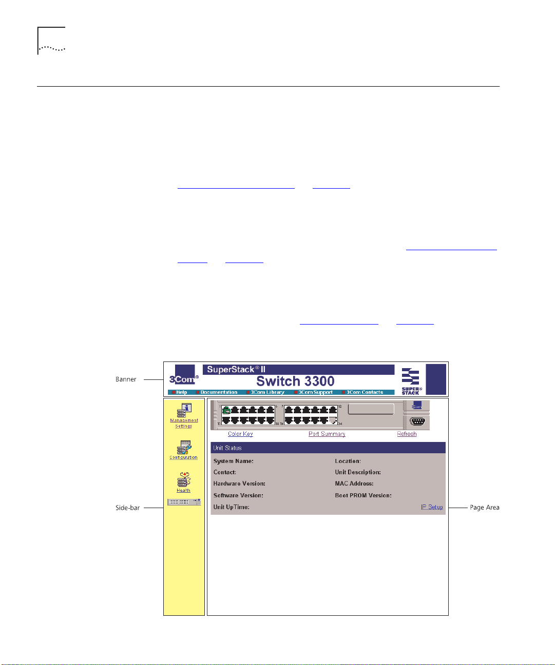
The Main Web Interface
The main web interface is made up of three areas:
■
The Banner
This is always displayed at the top of the browser window. It displays
the name of the current Switch in the stack, and contains several
External Link icons that allow you to access information outside of the
web interface. For more information about the External Links, see
“The External Link Icons”
■
The Side-bar
on page 49.
This is always displayed down the left side of the browser window. It
contains Management Icons that allow you to display web pages in
the page area (below). For more information, see “The Management
Icons” on page 50.
■
The Page Area
This is always displayed in the center of the browser window. It
contains the various web pages that allow you to manage the stack.
For more information, see “The Page Area”
Figure 4
Parts of the main web interface
on page 50.
Page 49

The Main Web Interface 49
The External Link
Icons
The banner of the main web interface contains several External Link icons
that allow you to access information outside of the interface; these are
shown in Ta b le 6
Tab le 6
External Link Icon Action
External Link icons and their actions
.
If your management workstation has access to the World
Wide Web, clicking the 3Com icon displays the home page of
the 3Com World Wide Web site in a second browser window.
If you have set up the online help, clicking the Help icon
displays the help for the web interface in a second browser
window.
For information about setting up the online help, see
“Installing Online Help and Documentation”
page 34
If you have set up the online documentation, clicking the
Documentation icon allows you to access the User Guides and
Management Guide for the stack in a second browser
window.
For information about setting up the online documentation,
see
page 34
.
“Installing Online Help and Documentation”
.
on
on
If your management workstation has access to the World
Wide Web, clicking the 3Com Library icon displays the Online
Library of the 3Com World Wide Web site in a second
browser window.
If your management workstation has access to the World
Wide Web, clicking the 3Com Support icon displays support
information from the 3Com World Wide Web site in a second
browser window.
If your management workstation has access to the World
Wide Web, clicking the 3Com Contacts icon displays contact
information from the 3Com World Wide Web site in a second
browser window.
Page 50

50 C
HAPTER
3: W
ORKING WITH THE WEB INTERFACE
The Management
Icons
The side-bar of the main web interface contains several Management
Icons that allow you to display web pages in the page area; these are
shown in Ta b le 7
Tab le 7
Management Icon Action
Management Icons and their actions
.
Management Settings — Click on this icon to display the
Management Settings pages for the stack.
Configuration — Click on this icon to display the
Configuration pages for the stack.
Health — Click on this icon to display the Health pages for
the current Switch unit in the stack.
Unit — Click on this icon to display the Unit pages for the
current Switch unit in the stack. To display the Unit pages for
a specific unit in a stack, click on that unit in the Unit icon.
The Page Area
For an overview of the pages accessed using these icons, see “The Page
Area” on page 50.
The page area of the main web interface contains web pages that allow
you to manage the stack. The web pages are grouped into four
categories:
■
Unit Pages
— These pages allow you to configure the current Switch
in the stack and the ports on that Switch:
Switch Graphic
■
— This page contains a graphic of the Switch that
allows you to display the status of the ports. It is always displayed
above the other Unit pages.
Color Key
■
— This page allows you to display the color-coding
information used by the Switch Graphic page.
Port Summary
■
— This page allows you to display the speed and
duplex mode of the ports shown in the graphic on the Switch
Graphic page.
Page 51

The Main Web Interface 51
■
Unit Status
— This page allows you to display the general
administration details of the Switch.
■
IP Setup
— This page allows you to set up IP information for the
Switch.
■
Port Setup
— This page allows you to configure individual ports
on the Switch.
■
Console Port Configuration
— This page allows you to configure
the console port of the Switch.
For more information, see “Configuring the Current Switch”
page 54
■
Management Settings Pages
.
— These pages allow you to change
the management settings for the stack:
■
System Name
— This page allows you to specify a descriptive
name for the stack.
■
Password Setting
— This page allows you to change your
password.
■
Location
— This page allows you to specify the physical location
of the stack.
■
Getting Started
— This page allows you to access the Getting
Started pages for the stack.
on
■
Documentation
— This page allows you to specify the location of
the online help and documentation for the stack.
■
Contact
— This page allows you to specify the details of a person
to contact about the stack.
For more information, see “Changing the Management Settings for
the Stack” on page 67.
■
Configuration Pages
— These pages allow you to configure the
stack as a whole:
■
VLAN Setup
— This page allows you to configure VLANs for the
stack.
■
Switch Database
— This page allows you to configure the Switch
Database of the stack.
■
Software Upgrade
— This page allows you to upgrade the
management software of the Switch units in the stack.
Page 52

52 C
HAPTER
3: W
ORKING WITH THE WEB INTERFACE
■
Roving Analysis Setup
— This page allows you to set up roving
analysis ports for the stack.
■
Resilient Links
— This page allows you to set up resilient links for
the stack.
■
— This page allows you to reset the Switch units in the
Reset
stack.
■
Port Trunks Setup
— This page allows you to set up port trunks
for the stack.
■
Initialize
— This page allows you to initialize the Switch units in
the stack.
■
Advanced Stack Setup
— This page allows you to configure the
advanced settings of the stack.
For more information, see “Configuring the Stack”
■
Health Pages
— These pages allow you to display statistics for the
on page 71.
current Switch in the stack:
■
Unit Graph
— This page allows you to display a range of statistics
for all the ports on the Switch.
■
Port Graph
— This page allows you to display a range of statistics
for a specific port on the Switch.
For more information, see “Displaying Statistics for the Current
Switch” on page 91.
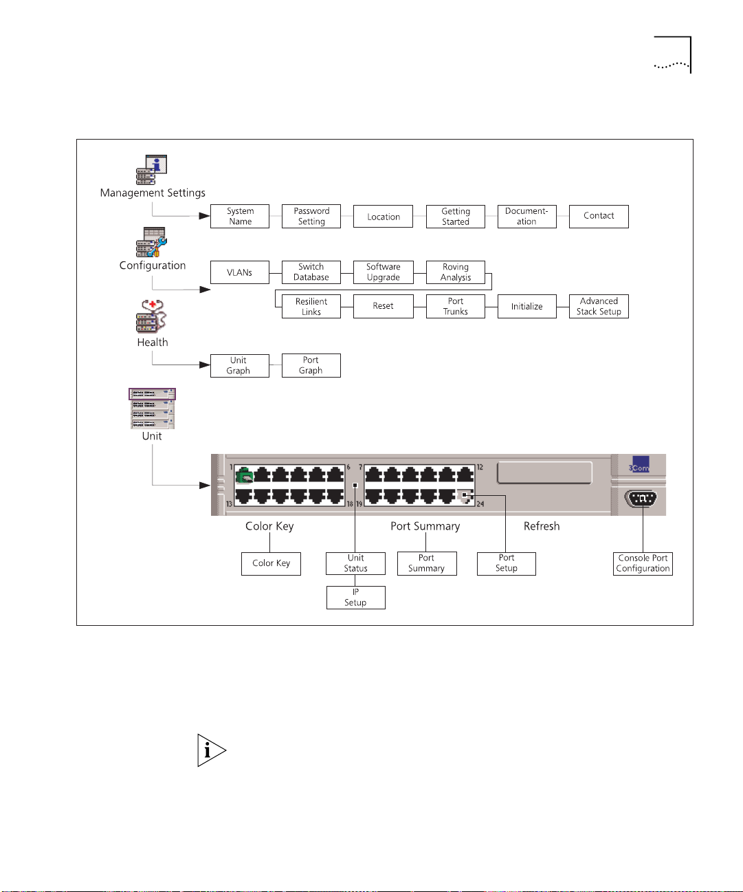
Navigating the Page Area
To access the first page of each category, click on the relevant
Management Icon on the side-bar; to access the remaining pages in the
category, click on the underlined hotlinks that are displayed at the top of
each page.
There are four exceptions to the navigation system. The Color Key page,
Port Summary page, Port Setup page and Console Port Configuration
page are accessed from the Switch Graphic page.
Figure 5
shows you how to access each of the web pages.
Page 53
The Main Web Interface 53
Figure 5
Web interface map
Making Changes in the Page Area
If you change any setting on a page in the page area, you
Apply
button at the bottom right of the page to make the change to the
stack. The change is only made when you click the
Apply
must
button.
click the
If you make changes on a page but do not wish to apply them, click the
Back button in your Web browser to exit the page.
Page 54

54 C
HAPTER
3: W
ORKING WITH THE WEB INTERFACE
Configuring the Current Switch
Displaying the Status
of the Ports
You can configure the current Switch and the ports on that Switch using
the Unit Pages. These pages allow you to:
■
Display the status of the ports on the Switch
■
Display the general administration details of the Switch
■
Set up IP information for the Switch
■
Configure individual ports on the Switch
■
Configure the console port of the Switch
You can display the status of ports on the Switch using the Switch
Graphic page.
To access the page:
■
Click the
displayed, containing a graphic of the Switch similar to Figure 6
Unit
icon on the side-bar. The Switch Graphic page is
. Note
that this page is always displayed above the other Unit pages.
Figure 6
The Switch graphic
Displaying the Color Codes Used by the Switch Graphic
The Switch graphic indicates the status of a port using color-coding:
■
Green — Enabled, connected
■
Black — Enabled, disconnected
■
Gray (with connection) — Disabled, connected
■
Gray (without connection) — Disabled, disconnected
You can display the color-coding information using the Color Key page.
To access the page, click the
Color Key
hotlink under the Switch graphic.
Page 55

Configuring the Current Switch 55
Displaying the Speed and Duplex Mode of Ports
You can display the speed and duplex mode of ports in the Switch
graphic using the Port Summary page.
To access the page:
■
Click the
Summary
Summary page is displayed as shown in Figure 7
hotlink under the Switch graphic. The Port
.
Figure 7
The Port Summary page
If you have an Expansion Module fitted to your Switch, the Expansion
Module port numbers follow on sequentially from the number of fixed
ports.
Refreshing the Switch Graphic
The Switch graphic does not update itself automatically — if you make a
change to the status of a port, you need to click the
Refresh
hotlink
positioned under the Switch graphic. If, after clicking Refresh, the Switch
graphic does not update, you may need to make a small change to your
Web browser; for more information, see “Solving Web Interface
Problems” on page 214.
Page 56
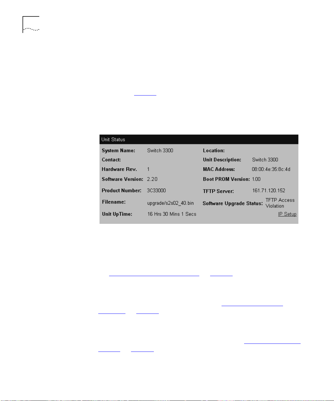
56 C
HAPTER
3: W
ORKING WITH THE WEB INTERFACE
Displaying
Administration
Details
You can display general administration details about the Switch using the
Unit Status page.
To access the page:
■
Click the
shown in Figure 8
Unit
icon on the side-bar. The Unit Status page is displayed as
. Some fields are only displayed after a software
upgrade failure. These fields display information about the software
upgrade.
Figure 8
The Unit Status page
The Unit Status page contains the following elements:
System Name
Displays the name given to the Switch during the Getting Started
procedure. For information about assigning a new name for the Switch,
see “Specifying a Descriptive Name”
on page 67.
Location
Displays the physical location of the Switch. For information about
assigning a new location for the Switch, see “Specifying a Physical
Location” on page 69.
Contact
Displays the details of a person to contact about the Switch. For
information about assigning new contact details, see “Specifying Contact
Details” on page 71.
Unit Description
Displays the product name of the Switch.
Page 57

Configuring the Current Switch 57
Hardware Rev
Displays the version number of the Switch hardware.
MAC Address
Displays the MAC (Ethernet) address assigned to the Switch.
Software Version
Displays the version number of the management software currently
installed on the Switch. For information about how to upgrade the
management software, see “Upgrading Management Software”
page 89
.
on
Boot PROM Version
Displays the version of Boot PROM software installed on the Switch.
Product Number
Displays the 3Com product number of the unit.
TFTP Server (optionally displayed)
Displays the IP address of the last TFTP server used to upgrade the unit’s
management software.
Filename (optionally displayed)
Displays the name of the management software file that was used during
the last software upgrade attempt.
Software Upgrade Status (optionally displayed)
Displays the reason for a software upgrade failure.
Unit Uptime
Displays the time that has elapsed since the Switch was last reset,
initialized or powered-up.
Page 58
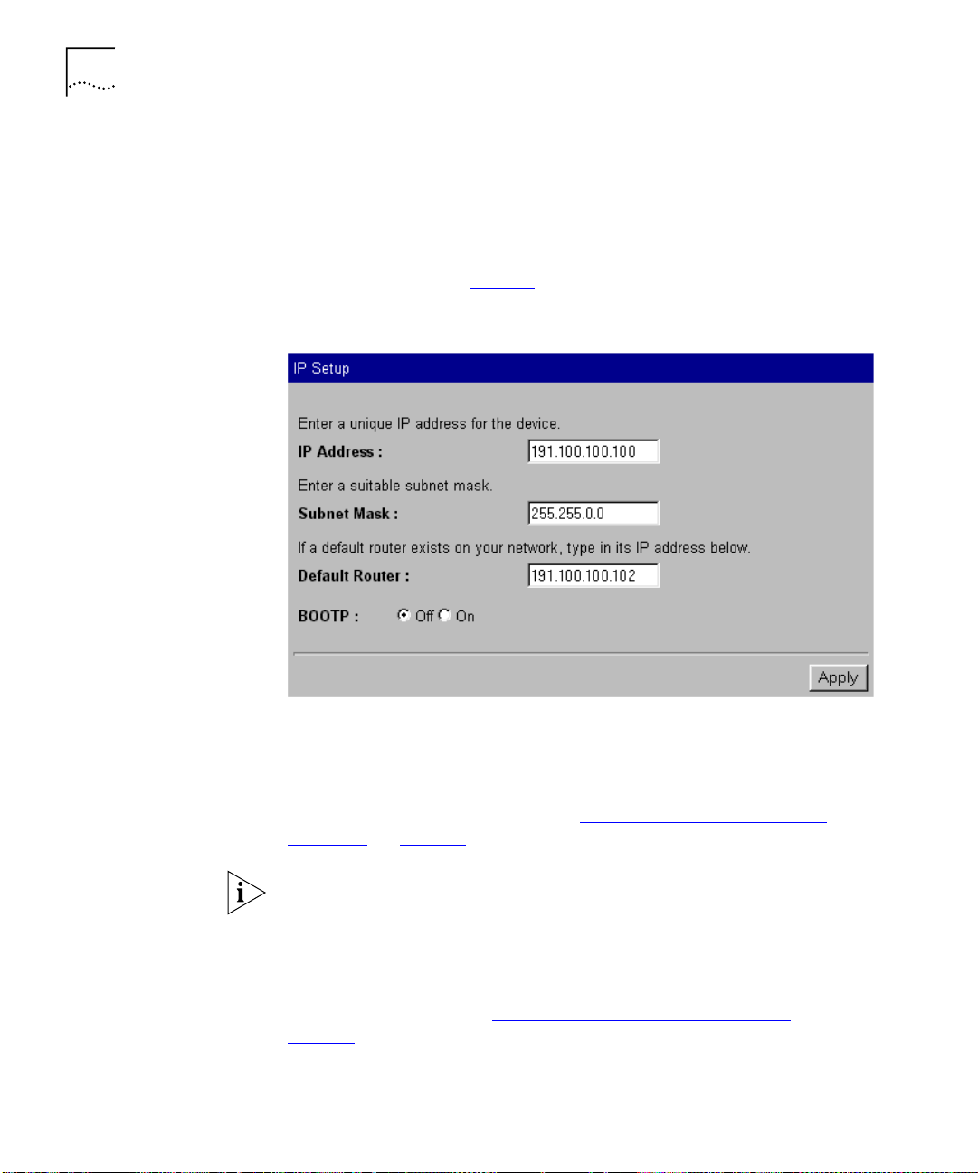
58 C
HAPTER
3: W
ORKING WITH THE WEB INTERFACE
Setting Up IP
Information
You can set up the IP information for the Switch using the IP Setup page.
To access the page:
Click the
1
Click the
2
displayed as shown in Figure 9
Figure 9
Unit
icon on the side-bar. The Unit Status page is displayed.
IP Setup
hotlink on the Unit Status page. The IP Setup page is
.
The IP Setup page
The IP Setup page contains the following elements:
IP Address
Allows you to enter a unique IP address for the Switch. For more
information about IP addresses, see “Managing a Switch Over the
Network” on page 38.
If you change the IP address of the Switch, you can no longer access the
web interface unless you enter the new IP address in the Location field of
your browser.
Subnet Mask
Allows you to enter a subnet mask for the Switch. For more information
about subnet masks, see “Subnets and Using a Subnet Mask”
page 39
.
on
Page 59

Configuring the Current Switch 59
Default Router
If your network contains one or more routers, this field allows you to
enter the IP address of the default router. For more information about IP
addresses, see “Managing a Switch Over the Network”
BOOTP
On / Off
on page 38.
If you have a BOOTP server on your network, these radio buttons allow
you to specify whether the server allocates IP information for the Switch
automatically.
For BOOTP to work correctly, the Switch must have the IP address 0.0.0.0.
If the Switch has another IP address, you must change the address to
0.0.0.0 and then reset the Switch.
The Switch only requests IP information from the BOOTP server 12 times.
If the Switch has not received the information by the 12th time, you must
reset the Switch and start again.
After BOOTP is enabled, you need to power cycle the unit before BOOTP
starts operating
Configuring a Port
You can configure individual ports on the Switch using the Port Setup
page.
To access the page:
Click the
1
Click the relevant port on the Switch graphic. The Port Setup page is
2
displayed as shown in Figure 10
icon on the side-bar.
Unit
or Figure 11.
Page 60

60 C
HAPTER
3: W
ORKING WITH THE WEB INTERFACE
Figure 10
Figure 11
The Port Setup page with auto-negotiation enabled
The Port Setup page with auto-negotiation disabled
Page 61

Configuring the Current Switch 61
The Port Setup page contains the following elements:
Port
Displays the number of the selected port.
Link State
Enabled
/ Disabled
Displays the state of the link connected to the port.
Media Type
Displays the media type of the link connected to the port.
Port Speed
Displays the current speed and duplex mode of the port. FC indicates that
flow control is enabled.
Auto-negotiation
Enabled
/ Disabled
Allows you to specify whether auto-negotiation is enabled for twisted
pair ports:
■
If auto-negotiation is enabled on a 10BASE-T/100BASE-TX port, the
speed and duplex mode of the link is automatically detected and set
accordingly. (See the note below headed Switch 610 and
Switch 1100.)
■
If auto-negotiation is enabled on a 10BASE-T port, the duplex mode
of the link is automatically detected and set accordingly.
■
If auto-negotiation is disabled, the speed and duplex mode of the port
is set using the Speed/Duplex listbox.
CAUTION:
The duplex mode of a link is not detected if the port on the
other end of the link is not auto-negotiating. In this case, the Switch port
is set to operate in half duplex:
■
If you want the link to operate in full duplex, set the Switch port to
operate in full duplex using the Speed/Duplex listbox.
■
If you want the link to operate in half duplex, set the port on the other
end of the link to half duplex.
Fiber ports and Transceiver Module ports are not auto-negotiating. If the
port is one of these ports, the Auto-negotiation listbox is set to
Disabled
and you cannot change it.
With auto-negotiation enabled, the Speed/Duplex listbox and Full Duplex
Flow Control listbox display
Auto
and cannot be set manually.
Page 62

62 C
HAPTER
3: W
ORKING WITH THE WEB INTERFACE
Switch 610 and Switch 1100 only
. The 10BASE-T/100BASE-TX ports on
the Switch 1100 cannot auto-negotiate IEEE802.3x flow control. Follow
the instructions below to enable flow control on the Switch 1100
10BASE-T/100BASETX ports.
To enable flow control on the Switch 1100 10BASE-T/100BASE-TX ports:
From the Port Setup page, set the Auto-Negotiation listbox to disabled.
1
Apply
Click
2
Set the FD Flow Control listbox to
3
Configure the port to the desired speed and full duplex operation.
4
Click
5
Speed/Duplex
Apply
.
Enabled
.
.
100Mbps FD / 100Mbps HD / 10Mbps FD / 10Mbps HD /
Auto
If the port does not support auto-negotiation, or if auto-negotiation is
disabled, this listbox allows you to:
■
Specify the speed and duplex mode of 10BASE-T/100BASE-TX ports
(HD indicates half duplex, FD indicates full duplex).
■
Specify the duplex mode of 10BASE-T and 100BASE-FX ports.
If auto-negotiation is enabled, the listbox displays
Auto
and you cannot
change the speed or duplex mode of the port manually.
CAUTION:
To communicate without errors, both ends of a link must use
the same duplex mode.
Enabled / Disabled / Auto
FD Flow Control
If auto-negotiation is disabled, this listbox allows you to enable or disable
the IEEE 802.3x flow control that can be used when the port is operating
in full duplex. If auto-negotiation is enabled, the listbox displays
Auto
,
and you cannot change the flow control setting for the port manually.
Flow control prevents any packet loss that may occur on congested ports.
For IEEE 802.3x flow control to operate correctly, it must be enabled at
both ends of the link.
Page 63

Configuring the Current Switch 63
HD Flow Control
Enabled
/ Disabled
Allows you to enable or disable the Intelligent Flow Management flow
control that can be used when the port is operating in half duplex. Flow
control prevents any packet loss that may occur on congested ports.
The Half Duplex Flow Control listbox should be disabled if the port is
connected to multiple devices using a hub. If it is enabled, local traffic
between those multiple devices is inhibited.
802.1p Multicast Learning
Stack Default
/ Disabled
Allows you to specify whether the port uses IEEE 802.1p multicast
filtering (GMRP) to filter and forward multicasts automatically:
■
Stack Default
— The port takes the 802.1p multicast learning setting
from the Advanced Stack Setup page. For more information, see
“Configuring the Advanced Stack Settings”
■
Disabled
— The port does not use IEEE 802.1p multicast filtering. Use
on page 76.
this setting if the device at the other end of the link does not support
IEEE 802.1p.
For more information about IEEE 802.1p multicast filtering, see
“Multicast Filtering”
on page 189.
Untagged VLAN
Allows you to specify a single VLAN to which the port belongs. For more
information about VLANs, see “Virtual LANs (VLANs)”
on page 163.
If you want to move a port from the Default VLAN (VLAN 1) to another
VLAN, that VLAN must have information defined for it. If you select a
VLAN in the Untagged VLAN listbox that does not have information
defined for it (that is, one that has the description
then click the
Apply
button, the Create VLAN page is displayed allowing
Unassigned
) and you
you to enter information for that VLAN. Once you have entered the VLAN
information, the Port Setup page is re-displayed and the port is placed in
the VLAN. For information about the Create VLAN page, see
VLAN Information”
on
page 84
.
“Defining
If the port at the other end of the link supports VLT or 802.1Q tagging,
you can specify that the port belongs to multiple VLANs. To specify that
the port belongs to multiple VLANs using VLT tagging, set the VLT
Tagging listbox to
VLANs using 802.1Q tagging, see
page 166
.
Enable
. To specify that the port belongs to multiple
“Placing a Port in Multiple VLANs”
on
Page 64

64 C
HAPTER
3: W
ORKING WITH THE WEB INTERFACE
FWD Unknown VLAN Tags
Enabled / Disabled
/ Auto
Allows you to specify whether the port forwards traffic that uses
unknown IEEE 802.1Q tags. If 802.1Q VLAN learning is disabled, you can
specify:
■
Enabled
— Use this setting if the port is connected to a switch that
supports IEEE 802.1Q VLANs.
■
Disabled
— Use this setting if the port is connected to an endstation,
hub, bridge, router, or a switch that does not support IEEE 802.1Q
VLANs.
If 802.1Q VLAN learning is enabled, you can specify:
■
Auto
— Use this setting if you want the Switch to automatically
organize the forwarding of traffic containing unknown tags.
■
Enabled
— Use this setting if the port is connected to a switch that
supports IEEE 802.1Q VLANs, and you want to override the automatic
organization of traffic containing unknown tags.
For more information about forwarding VLAN traffic that uses unknown
tags, see “Forwarding Traffic Containing Unknown 802.1Q Tags”
page 168
Port State
.
Enabled
/ Disabled
on
Allows you to enable or disable the port (that is, turn the port on or off).
Security
Enabled
/ Disabled
Allows you to specify whether the port uses security to guard against
unauthorized users connecting devices to your network. When security is
enabled on a port, it enters Single Address Learning Mode. In this mode,
the Switch:
■
Removes all the MAC (Ethernet) addresses stored for the port in the
Switch Database.
■
Learns the address of the first packet it receives on the port.
■
Defines the address as a permanent entry.
Once the first address is learned:
■
The port is disabled if a different address is seen on the port.
■
No other address can be learned until security is disabled or the
address is manually removed from the database.
■
The address cannot be learned on another port until security is
disabled or the address is manually removed from the database.
Page 65

Configuring the Current Switch 65
You cannot enable security on a port that is part of a resilient link, or a
port that is part of a port trunk. For more information, see
Resilient Links”
on
page 79
“Port Trunks”
and
on
page 157
“Setting Up
.
PACE
Stack Default
/ Enabled / Disabled
Allows you to specify whether the port uses PACE (Priority Access Control
Enabled) to support multimedia traffic:
■
Stack Default
— The port takes the PACE setting from the Advanced
Stack Setup page. For more information, see “Configuring the
Advanced Stack Settings” on page 76.
■
Enabled
■
— Use this setting if the port is connected to:
A switch, bridge or router that does not support PACE, or has PACE
disabled
An endstation that has PACE enabled
■
■
Disabled
■
■
■
VLT Tagging
— Use this setting if the port is connected to:
A hub
A switch, bridge or router that has PACE enabled
An endstation that does not support PACE, or has PACE disabled
Enabled / Disabled
Allows you specify whether the port uses VLT (Virtual LAN Trunk) tagging.
By specifying that the ports at both ends of a link use VLT tagging, you
can create a VLT tagged link that carries traffic for all of the VLANs
defined on your Switch. For more information about VLT tagging, see
“Placing a Port in Multiple VLANs”
on page 166.
VLT tagging can only be used on links to legacy 3Com devices.
A port cannot use VLT tagging if:
■
It uses 802.1Q tagging — for more information about 802.1Q
tagging, see
■
It is the main or standby port of a resilient link, and the other port
“Placing a Port in Multiple VLANs”
on
page 166
.
does not use VLT tagging — for more information about resilient links,
“Setting Up Resilient Links”
see
■
It belongs to a port trunk — for more information about port trunks,
“Port Trunks”
see
on
page 157
on
.
page 79
.
You cannot disable VLT tagging if the port is part of a resilient link pair.
Page 66

66 C
HAPTER
3: W
ORKING WITH THE WEB INTERFACE
Configuring the
Console Port
802.1Q VLAN Learning
Stack Default
/ Disabled
Allows you to specify whether the port uses IEEE 802.1Q learning (GVRP)
to place ports in VLANs automatically:
■
Stack Default
— The port takes the 802.1Q VLAN learning setting
from the Advanced Stack Setup page. For more information, see
“Configuring the Advanced Stack Settings”
■
Disable
— The port does not use IEEE 802.Q learning. Use this setting
on page 76.
if the device at the other end of the link does not support IEEE
802.1Q.
If 802.1Q VLAN learning is enabled, the settings of the FWD Unknown
Tag listbox change — see the FWD Unknown Tag listbox description on
page 64
for more information.
For more information about IEEE 802.1Q VLAN learning, see “Using IEEE
802.1Q Learning” on page 167.
By default, the console port is configured for direct connection to a
terminal. You only need to change this configuration if you are
connecting a modem to the port. You can configure the console port of
the Switch using the Console Port Configuration page.
To access the page:
Click the
1
Click the console port on the Switch graphic. The Console Port
2
Configuration page is displayed as shown in Figure 12
Figure 12
Unit
icon on the side-bar.
The Console Port Configuration page
.
Page 67

Changing the Management Settings for the Stack 67
The Console Port Configuration page contains the following elements:
Changing the Management Settings for the Stack
Console connection
Termina l
/ Modem
Allows you to specify the device that you are connecting to the console
port.
Port Speed
AutoConfig
/ 1200 / 2400 / 4800 / 9600 / 19200
Allows you to specify the line speed (baud) of the console port. If you
select
AutoConfig
, the line speed of the port is automatically set to the
line speed of the terminal or modem.
For the AutoConfig system to work, you need to reset the Switch.
/ Hardware RTS/CTS
Flow Control
None
Allows you to specify the serial line flow control option suitable for your
terminal or modem. See the documentation accompanying your terminal
or modem if you are unsure of the correct setting.
You can change the management settings for the stack using the
Management Settings Pages. These pages allow you to:
■
Specify a descriptive name for the stack.
■
Change your password.
■
Specify the physical location of the stack.
Specifying a
Descriptive Name
■
Access the Getting Started pages for the stack.
■
Specify the location of the online help and documentation for the
stack.
■
Specify the details of a person to contact about the stack.
You can specify a descriptive name for the stack using the System Name
page.
To access the page:
Click the
1
Click the
2
Management Settings
System Name
shown in Figure 13
hotlink. The System Name page is displayed as
.
icon on the side-bar.
Page 68

68 C
HAPTER
3: W
ORKING WITH THE WEB INTERFACE
Changing Your
Password
Figure 13
The System Name page
The Name field allows you to enter a descriptive name for the stack. The
name can be up to 20 characters long.
You can change the password for your user using the Password Setting
page.
To access the page:
Click the
1
Click the
2
displayed as shown in Figure 14
Figure 14
Management Settings
Password Setting
The Password Setting page
hotlink. The Password Setting page is
icon on the side-bar.
.
Page 69

Changing the Management Settings for the Stack 69
The Password Setting page contains the following elements:
New Password
Allows you to enter a new password for your user. The password can be
up to 10 characters long.
Passwords must only contain alpha-numeric characters.
Confirm Password
Allows you to re-enter the new password. The password does not change
unless you enter it in this field.
Specifying a Physical
Location
Accessing the Getting
Started Pages
You can specify the physical location of the stack using the Location
page.
To access the page:
Click the
1
Click the
2
Figure 15
Figure 15
Management Settings
Location
hotlink. The Location page is displayed as shown in
.
The Location page
icon on the side-bar.
The Getting Started pages allow you to enter basic setup information for
the stack.
To access the Getting Started pages:
Click the
1
Click the
2
Management Settings
Getting Started
icon on the side-bar.
hotlink. The first Getting Started page, Getting
Started - Introduction, is displayed.
For information about using the Getting Started pages, see “The Getting
Started Pages” on page 46.
Page 70

70 C
HAPTER
3: W
ORKING WITH THE WEB INTERFACE
Specifying the
Location of the
Online Help and
Documentation
You can specify the location of the online help and documentation for
the stack using the Documentation page.
To access the page:
Click the
1
Click the
2
as shown in Figure 16
Figure 16
Management Settings
Documentation
hotlink. The Documentation page is displayed
.
The Documentation page
icon on the side-bar.
The Documentation page contains the following elements:
Help
Allows you to specify the URL or file path of the online help for the stack.
If the files are installed on your management workstation, on the
CD-ROM, or on a network server, you must begin the file path with
file://
with
“Installing Online Help and Documentation”
. If the files are stored on a Web server, you must begin the URL
http://
. If you do not know where the online help is stored, see
on page 34.
Documentation
Allows you to specify the URL or file path of the online documentation for
the stack. If the files are installed on your management workstation, on
the CD-ROM, or on a network server, you must begin the file path with
file://
with
stored, see “Installing Online Help and Documentation”
. If the files are stored on a Web server, you must begin the URL
http://
. If you do not know where the online documentation is
on page 34.
Page 71

Configuring the Stack 71
Specifying Contact
Details
Configuring the Stack
You can specify the details of a person to contact about the stack using
the Contact page.
To access the Contact page:
Click the
1
Click the
2
Figure 17
Figure 17
Management Settings
Contact
hotlink. The Contact page is displayed as shown in
.
The Contact page
icon on the side-bar.
You can configure the stack using the Configuration pages. These pages
allow you to:
■
Configure the Switch Database of the stack
■
Configure the advanced settings of the stack
■
Set up resilient links for the stack
■
Set up port trunks for the stack
■
Configure VLANs for the stack
■
Set up roving analysis ports for the stack
■
Reset the Switch units in the stack
■
Initialize the Switch units in the stack
■
Upgrade the management software of the Switch units in the stack
If an existing stack with STAP enabled is powered-up with a new unit that
has STAP disabled, the setting of the new unit may override the whole
stack. A similar issue may also be encountered with the broadcast storm
control setting. The recommended procedure to overcome this problem is
to either (i) configure the new unit appropriately before adding it to the
stack or (ii) reconfigure the stack appropriately immediately after power-up.
Page 72

72 C
HAPTER
3: W
ORKING WITH THE WEB INTERFACE
Configuring the
Switch Database
You can configure the Switch Database of the stack using the Switch
Database page.
To access the page:
Click the
1
Click the
2
as shown in Figure 18
Configuration
icon on the side-bar.
Switch Database
.
hotlink. The Switch Database page is displayed
What is the Switch Database?
The Switch Database is used by the stack to determine if a packet should
be forwarded, and which port should transmit the packet if it is to be
forwarded. The database contains a list of entries, each containing three
items:
■
The MAC (Ethernet) address information from each endstation that
sends packets to the stack.
■
The port in the stack that receives packets from that endstation.
■
The Local ID of the VLAN to which the endstation belongs.
The number of addresses that the database can hold depends on the
number of Switch units in the stack. Each unit in the Switch 1100 family
provides support for 6,000 addresses, and each unit in the Switch 3300
family provides support for 12,000 addresses.
Figure 18
The Switch Database page
Page 73

Databases entries can have three states:
Configuring the Stack 73
■
Learned
— The stack has placed the entry into the Switch Database
when a packet was received from an endstation:
Learned entries are removed (aged out) from the Switch Database
■
if the stack does not receive packets from that endstation within a
certain period of time (the
ageing time
). This prevents the Switch
Database from becoming full with obsolete entries by ensuring
that when an endstation is removed from the network, its entry is
also removed from the database. For information about setting the
ageing time, see “Configuring the Advanced Stack Settings”
page 76
Learned entries are also removed from the Switch Database if the
■
.
stack is reset or powered-down.
■
Non-ageing learned
— If the ageing time is set to 0 seconds, all
learned entries in the Switch Database become non-ageing learned
entries. This means that they do not age, but they are still removed
from the database if the stack is reset or powered-down. For
information about setting the ageing time, see “Configuring the
Advanced Stack Settings” on page 76.
■
Permanent
— The entry has been placed into the Switch Database
using the Switch Database page. Permanent entries are not removed
from the Switch Database unless they are removed using the Switch
Database page or the stack is initialized.
on
Displaying the Switch Database
The Display Database Entries table on the Switch Database page displays
the Switch Database entries for the stack:
■
Unit
1 / 2 / 3 / 4
Displays the Switch unit in the stack that contains the port for the
entry.
■
Port
Displays the port for the entry.
■
VLAN
1 ... 16
Displays the local ID of the VLAN for the entry.
■
MAC Address
Displays the MAC (Ethernet) address for the entry.
■
Status
Learned / Permanent
Displays the state of the entry.
Page 74

74 C
HAPTER
3: W
ORKING WITH THE WEB INTERFACE
To display a subset of the entries for the
From the
1
Port Filter
listbox, select a port that has submitted the relevant
current
unit:
entries or All Ports.
From the
2
VLAN Filter
listbox, select the local ID of a VLAN associated with
the relevant entries.
3
In the
field, enter the first few characters of the MAC
Enter MAC Address
(Ethernet) address for the relevant entries.
From the
4
Click the
5
If there are more than 100 entries in the table, click the
6
Select Action Type
Apply
button. The subset of entries is displayed.
listbox, select Search.
Next Page
to display the next 100 entries.
To search for entries in the next VLAN, select Search Next from the
7
Action Type
listbox.
If you search for a specific MAC address, and the address is not in the
database, the Display Database Entries table displays the message
Database
.
To display the entire list of entries for all units in the stack:
From the
1
Select Action Type
listbox, select Display All.
button
Select
Not in
Click the
2
If there are more than 100 entries in the table, click the
3
Apply
button. The entire list of entries is displayed.
Next Page
button
to display the next 100 entries.
Inserting Permanent Entries
The Switch Database page allows you to insert permanent entries for the
current unit into the Switch Database.
To insert a permanent entry:
From the
1
From the
2
In the
3
Port Filter
VLAN Filter
listbox, select a port for the entry.
listbox, select the local ID of a VLAN for the entry.
Enter MAC Address
field, enter the MAC (Ethernet) address for the
entry.
From the
4
Click the
5
Select Action Type
Apply
button. The Display Database Entries table displays the
listbox, select Insert.
new entry.
Page 75

Configuring the Stack 75
The Display Database Entries table is not automatically updated with the
new entry. To update the table:
From the
a
Click the
b
Select Action Type
Apply
button.
listbox, select Display All.
When inserting a permanent entry, two error messages can be displayed
Status
in the
■
You can only insert an entry for one port at a time; if you select All
Ports in the
■
If you enter a MAC address that has an invalid format, the message
Bad Address
column of the Display Database Entries table:
Port Filter
listbox, the message
Port Needed
is displayed.
is displayed.
Deleting Entries
The Switch Database page allows you to delete entries from the Switch
Database.
To delete an entry:
1
In the
Enter MAC Address
field, enter the MAC (Ethernet) address for the
entry.
From the
2
Click the
3
Select Action Type
button. The Display Database Entries table displays the
Apply
entry with the message
listbox, select Delete.
Deleted
. If the entry contained a multicast
address, and the address is still stored against other ports or VLANs, the
table displays
Deleted on Port
.
The Display Database Entries table is not automatically updated with the
deletion. To update the table:
From the
a
Click the
b
Select Action Type
Apply
button.
listbox, select Display All.
You cannot delete entries that have been added by the multicast filtering
systems; if you try to delete one of these entries, the Display Database
Entries table displays the message
information about multicast filtering, see
page 189
.
Cannot Delete (Multicast)
“Multicast Filtering”
. For more
on
Page 76

76 C
HAPTER
3: W
ORKING WITH THE WEB INTERFACE
Configuring the
Advanced Stack
Settings
You can configure the advanced settings of the stack using the Advanced
Stack Setup page.
To access the page:
Click the
1
Click the
2
is displayed as shown in Figure 19
Figure 19
Configuration
Advanced Stack Setup
icon on the side-bar.
hotlink. The Advanced Stack Setup page
.
The Advanced Stack Setup page
The Advanced Stack Setup page contains the following elements:
Enabled / Disabled
PACE
Allows you to specify whether the ports in the stack use PACE (Priority
Access Control Enabled) to support multimedia traffic. For information on
specifying whether individual ports use PACE, see “Configuring a Port”
on page 59
Forwarding Mode
.
Fast Forward / Fragment Free / Store and Forward /
Intelligent
Allows you to set the forwarding mode for units in the stack that belong
to the Switch 1100/610 family:
■
Fast Forward
— Packets are forwarded as soon as the destination
address is received and processed. With Fast Forward, packets take a
very short time to be forwarded, but all error packets are propagated
onto the network because no time is allowed for checking.
■
Fragment Free
— Packets are forwarded when at least 512 bits of the
packet is received, which ensures that collision fragments are not
propagated through the network. With Fragment Free, packets take a
Page 77

Configuring the Stack 77
short time to be forwarded, but all error packets except fragments are
propagated.
■
Store and Forward
— Received packets are buffered entirely before
they are forwarded, which ensures that only good packets are
forwarded to their destination. With Store and Forward, packets take
slightly longer to be forwarded than with Fast Forward and Fragment
Free, but no errors are propagated.
■
Intelligent
— The stack monitors the amount of error traffic on the
network and changes the forwarding mode accordingly. Normally, the
stack is in Fast Forward mode. If the stack detects an error rate of
greater than 20 errored frames per second, the forwarding mode is
set to Store and Forward. It will return to Fast Forward mode once the
error rate drops to 1 errored frame per second.
Units in the Switch 3300/630 family only support the Store and Forward
forwarding mode. If the stack is set to another forwarding mode, these
units use the Store and Forward forwarding mode.
Spanning Tree
Enabled / Disabled
Allows you to specify whether the stack uses the Spanning Tree Protocol
(STP). Using STP makes your network more resilient to link failure and also
provides a protection from loops — one of the major causes of broadcast
storms; for more information, see “Spanning Tree Protocol”
page 193
CAUTION:
.
If you enable STP, the stack takes several seconds to configure
on
itself. During this time, you cannot communicate with the stack.
You cannot enable STP if you have set up resilient links on any Switch
units in your stack. For more information about resilient links, see
“Setting Up Resilient Links”
Broadcast Storm Control
page 79
on
Enabled
.
/ Disabled
Allows you to specify whether the stack uses Broadcast Storm Control. If
Broadcast Storm Control is enabled, the stack automatically creates an
alarm for each port to monitor the level of broadcast traffic on that port.
If the broadcast traffic level rises to 2976 frames per second, the
broadcast traffic on the port is blocked until the broadcast traffic level
drops to 1488 frames per second.
Page 78

78 C
HAPTER
3: W
ORKING WITH THE WEB INTERFACE
Ageing Time (Secs)
Allows you to specify the ageing time (in seconds) for all learned entries
in the Switch Database of the stack; the default time is 1800 seconds (30
minutes). If you specify an ageing time of 0, the ageing process is
disabled and the learned entries become non-ageing learned entries. For
more information about the Switch Database, see “What is the Switch
Database?” on page 72.
60 ... 1000000
0 /
FastIP
Enabled
Disabled
/
Allows you to specify whether the stack uses FastIP to reduce the load on
routing devices when there is a large amount of inter-VLAN traffic on
your network. FastIP requires your stacks to support IEEE 802.1Q
learning; consequently, if you set the FastIP listbox to enabled, the
802.1Q VLAN Learning listbox is also set to enabled. For more
information about FastIP, see “FastIP”
CAUTION:
If you change the setting of the FastIP listbox, the stack needs
on page 181.
to be reset before the change comes into effect.
Enabled / Disabled
802.1Q VLAN Learning
Allows you to specify whether the ports in the stack use IEEE 802.1Q
learning (GVRP) to place ports in VLANs automatically. For more
information about IEEE 802.1Q VLAN learning, see “Using IEEE 802.1Q
Learning” on page 167.
Enabled / Disabled
802.1p Multicast Learning
Allows you to specify whether the ports in the stack use IEEE 802.1p
multicast filtering (GMRP) to filter and forward multicasts automatically.
For more information about IEEE 802.1p multicast filtering, see “IEEE
802.1p Multicast Filtering” on page 191.
Enabled / Disabled
IGMP Multicast Learning
Allows you to specify whether the ports in the stack use IGMP multicast
filtering to filter and forward multicasts automatically. For more
information about IGMP multicast filtering, see “IGMP Multicast
Filtering” on page 192.
Page 79
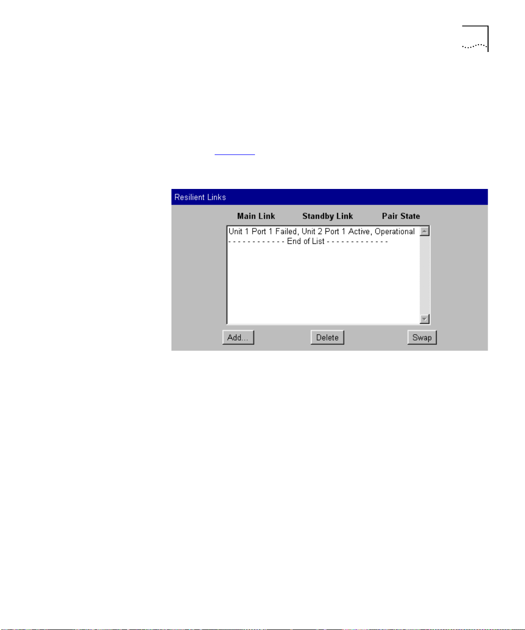
Configuring the Stack 79
Setting Up Resilient
Links
You can set up resilient links for the stack using the Resilient Links page.
To access the page:
Click the
1
Click the
2
Configuration
Resilient Links
shown in Figure 20
Figure 20
The Resilient Links page
icon on the side-bar.
hotlink. The Resilient Links page is displayed as
.
What are Resilient Links?
The Resilient Link feature enables you to protect critical links and prevent
network downtime if those links fail. A resilient link is comprised of a
resilient link pair
containing a main link and a standby link. If the main
link fails, the standby link immediately and automatically takes over the
task of the main link.
The resilient link pair is defined by specifying a main port and a standby
port at one end of the link.
During normal operation, the main port is enabled and the standby port
is disabled. If the main link fails, the main port is disabled and the standby
port is enabled. If the main link becomes operational, you can then
re-enable the main port and disable the standby port again.
When setting up resilient links, note the following:
■
Resilient link pairs cannot be set up if the stack uses the Spanning Tree
Protocol (STP).
Page 80

80 C
HAPTER
3: W
ORKING WITH THE WEB INTERFACE
■
Resilient link pairs can only be set up using fiber or twisted pair ports.
The main and standby ports in the same pair, however, can use any
combination of these media.
■
A resilient link pair must only be defined at one end of the link.
■
A resilient link pair must only be set up if:
The ports belong to the same VLANs.
■
The ports use the same VLAN tagging system (802.1Q tagging or
■
VLT tagging).
The ports have the same IEEE 802.1Q VLAN learning setting.
■
The ports have the same IEEE 802.1p multicast learning setting.
■
Neither of the ports are secure ports (have security enabled).
■
Neither of the ports are part of a port trunk.
■
Neither of the ports belong to another resilient link pair.
■
■
The port state of ports in a resilient link pair cannot be changed unless
a link failure occurs.
Displaying Resilient Link Pairs
The Resilient Links page displays the resilient link pairs that are set up for
the stack:
■
Main Link
Unit 1 Port 1 / Unit 1 Port 2 / ...
Displays the port in the stack that is the main port of the resilient link
pair, and the state of the link on that port.
■
Standby Link
Unit 1 Port 1 / Unit 1 Port 2 / ...
Displays the port in the stack that is the standby port of the resilient
link pair, and the state of the link on that port.
■
Pair State
Operational / Not Operational
Displays whether the resilient link pair is operational or not. When the
pair is operational, either the main port or the standby port can
forward traffic.
Creating a Resilient Link Pair
The Resilient Links page allows you to create a resilient link pair. To do
this:
Click the
1
Select the Switch units that are to contain the main port and standby port
2
Add...
button. The first Add Resilient Links page is displayed.
of the resilient link pair.
Page 81

Configuring the Stack 81
Click the
3
From the
4
Click the
5
From the
6
button.
Next...
Main Link
Next...
field, select the main port of the resilient link pair.
button.
Standby Link
field, select the standby port of the resilient link
pair.
Click the
7
button. The Resilient Links page is displayed showing the
Next...
new resilient link pair.
Deleting a Resilient Link Pair
The Resilient Links page allows you to delete a resilient link pair. To do
this:
Click the resilient link pair.
1
Click the
2
Delete
button.
Swapping the Active Port of a Resilient Link Pair
The Resilient Links page allows you to swap the active (or enabled) port of
a resilient link pair. To do this:
Click the resilient link pair.
1
Click the
2
Swap
button.
Setting Up Port
Trunks
You can set up port trunks for the stack using the Port Trunk Setup page.
To access the page:
Click the
1
Click the
2
Configuration
Port Trunks
shown in Figure 21
icon on the side-bar.
hotlink. The Port Trunks Setup page is displayed as
.
Page 82

82 C
HAPTER
3: W
ORKING WITH THE WEB INTERFACE
Figure 21
The Port Trunk Setup page
What are Port Trunks?
Port trunks are connections that allow devices to communicate using up
to four links in parallel. Port trunks provide two benefits:
■
They can potentially double, triple or quadruple the bandwidth of a
connection.
■
They can provide redundancy — if one link is broken, the other links
share the traffic for that link.
For more information, see “Port Trunks”
on page 157.
Displaying the Ports that Belong to Each Port Trunk
The Port Trunks Setup page allows you to display the ports that belong to
each port trunk. To do this:
From the
1
Click the
2
are available to be placed in the port trunk. The
Port Trunks Available
Select
button. The
listbox, select a port trunk.
Available Ports
listbox displays the ports that
Trunk Members
listbox
displays the ports that belong to the port trunk.
Placing Ports in a Port Trunk
The Port Trunks Setup page allows you to place ports in port trunks. To do
this:
From the
1
Click the
2
Port Trunks Available
Select
button.
listbox, select a port trunk.
Page 83

Configuring the Stack 83
Configuring VLANs
Click a port in the
3
Click the
4
Add >>
port is displayed in the
Available Ports
button. The port is assigned to the port trunk, and the
Trunk Mem be rs
listbox.
listbox.
There are several conditions that need to be satisfied before a port can be
placed in a port trunk. See
To place a port back in the
Trunk Members
listbox and click the
“Port Trunks and Your Switch”
Available Ports
listbox, click the port in the
<< Remove
(primary) port cannot be placed back in the
button. The first
Available Ports
page 158
on
listbox until
the other ports are placed back.
You can configure VLANs for the stack using the VLAN Setup page.
To access the page:
Click the
1
Click the
2
Figure 22
Figure 22
Configuration
hotlink. The VLAN Setup page is displayed as shown in
VLANs
.
The VLAN Setup page
icon on the side-bar.
.
Page 84

84 C
HAPTER
3: W
ORKING WITH THE WEB INTERFACE
What are VLANs?
A VLAN is a flexible group of devices that can be located anywhere in a
network, but they communicate as if they are on the same physical
segment. With VLANs, you can segment your network without being
restricted by physical connections — a drawback of traditional network
design. For more information about VLANs, see “Virtual LANs (VLANs)”
on page 163
Defining VLAN Information
The VLAN Setup page allows you to define the required information
about VLANs. To do this:
.
Click the
1
In the
2
Create...
VLAN Name
button. The Create VLAN page is displayed.
field, enter a descriptive name for the VLAN (for
example, Marketing or Management). The name can be up to 32
characters long.
3
In the
field, enter a unique 802.1Q ID for the VLAN. The
802.1Q VLAN ID
802.1Q ID is used to identify the VLAN if you use 802.1Q tagging across
your network, and can be any number between 2 and 4094. You only
need to enter an ID in the 802.1Q VLAN ID field if you intend to use
802.1Q tagging on your network.
4
In the
listbox, enter a local ID for the VLAN. The local ID is used to
Local ID
identify the VLAN within the stack, and can be any number between 2
and 16 (VLAN 1, the Default VLAN, is already created and cannot be
deleted). The Local ID corresponds to the VLAN IDs used in legacy 3Com
devices.
5
Click
. The VLAN information is defined, and the VLAN Setup page
Apply
is displayed showing the port membership for the new VLAN.
Editing VLAN Information
The VLAN Setup page allows you to edit any VLAN information. To do
this:
From the
1
VLANs Available
listbox, select a VLAN.
Click the
2
Click the
3
Edit the required information.
4
Click
5
Select
button.
Edit...
button. The Edit VLAN page is displayed.
Apply
. The VLAN information is edited, and the VLAN Setup page is
displayed.
Page 85

Configuring the Stack 85
You cannot edit the 802.1Q VLAN ID if ports are already assigned to the
VLAN.
Deleting VLAN Information
The VLAN Setup page allows you to delete any VLAN information that
you define in the Create VLAN page. To do this:
From the
1
Click the
2
Click the
3
VLANs Available
button.
Select
button. The VLAN is deleted, and the VLAN Setup page
Delete
listbox, select a VLAN.
displays the port membership of the Default VLAN.
You cannot delete the information for a VLAN if ports are assigned to
that VLAN.
Displaying the Ports that Belong to Each VLAN
The VLAN Setup page allows you to display the ports that belong to each
VLAN. To do this:
From the
1
Click the
2
VLANs Available
button. The
Select
the stack that are available to be placed in the VLAN. The
listbox, select a VLAN.
Available Ports
listbox displays the ports in
VLAN Members
listbox displays the ports in the stack that belong to the VLAN.
Placing Ports in Single VLANs
To place a port in a single VLAN, use the Untagged VLAN listbox on the
Port Setup page; see “Configuring a Port”
on page 59.
Placing Ports in Multiple VLANs Using VLT Tagging
To place a port in multiple VLANs using VLT tagging, use the VLT Tagging
listbox on the Port Setup page; see “Configuring a Port”
on page 59.
Placing Ports in Multiple VLANs Using 802.1Q Tagging
The VLAN Setup page allows you to place a port in multiple VLANs using
802.1Q tagging. To do this:
From the
1
Click the
2
Click the relevant port in the
3
Click the
4
is displayed in the
VLANs Available
button.
Select
Add >>
button. The port is assigned to the VLAN, and the port
VLAN Members
listbox, select a VLAN.
Available Ports
listbox.
listbox.
Page 86

86 C
HAPTER
3: W
ORKING WITH THE WEB INTERFACE
To place the port in another VLAN, repeat steps 1 to 4 with that VLAN.
5
Setting Up Roving
Analysis Ports
To place a port back in the
Available Ports
VLAN Members listbox and click the
The
VLAN Members
listbox displays two types of port that do not use
listbox, click the port in the
<< Remove
button.
802.1Q tagging: untagged ports and VLT tagged ports. These ports
cannot be moved from the VLAN using the VLAN Setup page:
■
To remove an untagged port from a VLAN, change its VLAN allocation
using the
■
VLT tagged ports belong to all VLANs. To remove a VLT tagged port
Untagged VLAN
listbox on the Port Setup page.
from a VLAN, specify that the port is no longer VLT tagged using the
VLT Tagging
listbox on the Port Setup page.
You can set up roving analysis ports for the stack using the Roving
Analysis Setup page.
To access the page:
Click the
1
Click the
2
displayed as shown in Figure 23
Figure 23
Configuration
Roving Analysis
icon on the side-bar.
hotlink. The Roving Analysis Setup page is
.
The Roving Analysis Setup page
Page 87

Configuring the Stack 87
What is Roving Analysis?
Roving analysis is a system that allows you to attach a network analyzer
to one port and use it to monitor the traffic of other ports in the stack.
The system works by enabling you to define an analysis port (the port
that is connected to the analyzer), and a monitor port (the port that is to
be monitored). Once the pair are defined, and you enable the system, the
stack takes all the traffic going in and out of the monitor port and copies
it to the analysis port.
Roving analysis is used when you need the functions of a network
analyzer, but do not want to change the physical characteristics of the
monitored segment by attaching an analyzer to that segment.
Defining Monitor Ports and Analysis Ports
The Roving Analysis Setup page allows you to define monitor ports and
analysis ports.
To define a monitor port and analysis port:
Click a port in the
1
Available Monitor Ports
listbox to specify the monitor
port.
Click a port in the
2
Available Analysis Ports
listbox to specify the analysis
port.
Click
3
CAUTION:
.
Apply
The analysis port should have a higher bandwidth than the
monitor port. Otherwise, the roving analysis system cannot copy all the
traffic effectively.
If a port belongs to a port trunk, you cannot specify that it is a monitor
port or an analysis port. Consequently, it is not displayed in the
Monitor Ports
listbox or the
Available Analysis Ports
listbox.
Available
An analysis port must be in the same VLANs as the monitor port it is
copying. We therefore recommend that you manually place your analysis
ports in all the VLANs used by the stack.
Page 88

88 C
HAPTER
3: W
ORKING WITH THE WEB INTERFACE
Enabling the Roving Analysis System
The Roving Analysis Setup page allows you to enable the roving analysis
system. To do this:
Resetting All the
Units in the Stack
From the
1
Click
2
Roving Analysis State
Apply
.
listbox, select
Enabled
.
You can reset all the Switch units in the stack using the Reset page.
To access the page:
Click the
1
Click the
2
To reset the stack, select
Configuration
Reset
hotlink. The Reset page is displayed.
icon on the side-bar.
Yes
and then click
Apply
.
What Happens During a Reset?
Resetting the Switch units in the stack simulates a power-off/on cycle.
You may want to do this if you need to:
■
Remove all the Learned entries in the Switch Database (SDB).
■
Reset the statistic counters of the stack.
CAUTION:
Resetting the stack causes some of the traffic being
transmitted over the network to be lost. It also clears all Learned entries
from the Switch Database.
The stack takes about 10 seconds to reset. While the stack is resetting,
you cannot communicate with it.
Initializing All the
Units in the Stack
You can initialize all the Switch units in the stack using the Initialize page.
To access the page:
Click the
1
Click the
2
To initialize the stack, select
Configuration
Initialize
hotlink. The Initialize page is displayed.
icon on the side-bar.
Yes
and then click
Apply
.
What Happens During an Initialization?
Initializing the Switch units in the stack returns them to their default
(factory) settings. The only information that does not return to its default
Page 89

Configuring the Stack 89
setting is the IP and SLIP information, which is retained to ensure that you
can continue managing the stack. You may want to initialize the stack if it
has previously been used in a different part of your network, and its
settings are incorrect for the new environment.
Upgrading
Management
Software
CAUTION:
Use great care when initializing the stack — it removes all
configuration information, including password and security information.
CAUTION:
When initializing the stack, network loops may occur if you
have set up port trunks, resilient links, VLANs, or the Spanning Tree
Protocol. Before initializing the stack, ensure you have disconnected the
cabling for all standby or duplicate links.
The stack takes about 10 seconds to initialize. While the stack is
initializing, you cannot communicate with it.
You can upgrade the management software of all Switch units in the
stack using the Software Upgrade page.
To access the page:
Click the
1
Click the
2
Configuration
Software Upgrade
displayed as shown in Figure 24
Figure 24
The Software Upgrade page
icon on the side-bar.
hotlink. The Software Upgrade page is
.
Page 90

90 C
HAPTER
3: W
ORKING WITH THE WEB INTERFACE
To upgrade the management software:
Copy the software upgrade file into an appropriate directory on a TFTP
1
server. For information on using a TFTP Server, see the documentation
that accompanies it.
CAUTION:
You must ensure that the port connected to the TFTP server
has 802.1Q VLAN learning disabled and belongs to the Default VLAN
(VLAN 1). The server can only upgrade a stack if it is connected to the
stack by the Default VLAN.
You can download a TFTP server called 3CServer (filename: 3cs117.zip)
from 3Com’s website
http://www.3com.com
. 3CServer can be installed
and run on a Microsoft Windows® 95/98 or NT system.
Enter the name of the software upgrade file in the
2
Filename
field. The
filename format is:
s2sxx_yy.bin
where
CAUTION:
xx_yy
is the version of management software.
You must use the
s2sxx_yy.bin
format, otherwise the
upgrade fails.
Enter the IP address of the TFTP server in the
3
Click the
4
Apply
button. During the upgrade, the Power/Self Test LED
Server Address
field.
flashes green and the command line interface is locked. The units in the
stack upgrade one at a time, and each unit takes about 5 minutes; when
the upgrade is complete, the Switch units in the stack are reset.
CAUTION:
During the upgrade, do not power-down or reset any Switch
units in the stack.
Page 91

Displaying Statistics for the Current Switch 91
Displaying Statistics for the Current Switch
Displaying Unit
Statistics
You can display statistics for the current Switch in the stack using the
Health pages. These pages allow you to:
■
Display a range of statistics for all the ports on the Switch
■
Display a range of statistics for a specific port on the Switch
You can display a range of statistics for all the ports on the Switch using
the Unit Graph page.
To access the page:
Click the
1
Click the
2
icon on the side-bar.
Health
Unit Graph
hotlink. The Unit Graph page is displayed.
The graphs that can be displayed by the Unit Graph page are shown in
Figure 25
Figure 25
.
The graphs displayed by the Unit Graph page
You can choose to display graphs for
.
Errors
To display the Bandwidth Utilization graph:
From the listbox, choose
1
2
Click
Apply
.
Bandwidth Utilization
Bandwidth Utilization or Tot a l
.
Page 92

92 C
HAPTER
3: W
ORKING WITH THE WEB INTERFACE
To display the Total Errors graph:
From the listbox, choose
1
Apply
2
Click
.
Total Errors
.
If you click a port on the Bandwidth Utilization or Total Errors graph, the
graph for that port is displayed.
Interpreting the Statistics
■
The Bandwidth Utilization graph scales automatically to display the
percentage of bandwidth used on all ports of the Switch over the last
30 seconds:
A bandwidth utilization of 0–25% (green bar on the graph)
■
indicates that the ports are dealing with a light traffic load.
A bandwidth utilization of 26–85% (yellow bar on the graph)
■
indicates that the ports are dealing with a normal traffic load.
A bandwidth utilization of 86–100% (red bar on the graph)
■
indicates that the ports are dealing with a heavy traffic load. This
could be caused by a fault in your network, or an inadequate
network configuration.
■
The Total Errors graph scales automatically to display the total number
of packets with errors that have been seen on the ports of the Switch
over the last 30 seconds.
Displaying Port
Statistics
You can display a range of statistics for a specific port on the Switch using
the Port Graph page.
To access the page:
Click the
1
Click the
2
Health
icon on the side-bar.
Port Graph
hotlink. The Port Graph page is displayed.
The graphs that can be displayed by the Port Graph page are shown in
Figure 26
.
Page 93

Displaying Statistics for the Current Switch 93
Figure 26
The graphs displayed by the Port Graph page
You can choose to display graphs for
Size distribution
:
To display the Utilization graph:
1
From the first listbox, choose a port.
2
From the second listbox, choose
Click
Apply
.
3
To display the Total Errors graph:
1
From the first listbox, choose a port.
2
From the second listbox, choose
Click
Apply
.
3
Utilization, Total Errors
Utilization
Total Errors
.
.
or
Packet
Page 94

94 C
HAPTER
3: W
ORKING WITH THE WEB INTERFACE
To display the Packet Size Distribution graph:
From the first listbox, choose a port.
1
From the second listbox, choose
2
Apply
3
Click
.
Packet Size Distribution
.
Interpreting the Statistics
■
The Utilization graph scales automatically to display the percentage of
bandwidth used on the port over the last hour and last 48 hours:
A bandwidth utilization of 0–25% indicates that the port is dealing
■
with a light traffic load.
A bandwidth utilization of 26–85% indicates that the port is
■
dealing with a normal traffic load.
A bandwidth utilization of 86–100% indicates that the port is
■
dealing with a heavy traffic load. This could be caused by a fault in
your network, or an inadequate network configuration.
■
The Total Errors graph scales automatically to display the total number
of packets with errors that have been seen on the port over the last
hour and last 48 hours.
■
The Packet Size Distribution graph displays the proportion of packets
of certain sizes seen by the port over the last 30 seconds.
Page 95

W
ORKING
W
ITH THE
C
OMMAND
4
L
INE INTERFACE
This chapter describes how to access and use the command line interface.
It covers the following topics:
■
Accessing the Interface
■
About the Interface Menus
■
A Quick Guide to the Commands
■
Displaying and Changing Bridging/VLANs Information
■
Displaying and Changing Port Information
■
Displaying and Changing System Feature Information
■
Displaying and Changing IP-related Information
■
Displaying and Changing SNMP-related Information
■
Displaying and Changing Stack Information
Throughout this chapter, the term stack refers to a number of Switch
units that are managed as a single unit. However, a stack can contain a
single Switch.
Page 96

96 C
HAPTER
4: W
ORKING WITH THE COMMAND LINE INTERFACE
Accessing the Interface
To access the command line interface, take the following steps:
Set up your network for command line interface management; for more
1
information, see “Setting Up Command Line Interface Management”
page 36
. The login sequence for the command line interface begins as
soon as a relevant Switch in the stack detects a connection to its console
port, or as soon as a Telnet session is started.
If the login sequence does not begin immediately, press the [Return] key a
few times until it does begin. If the sequence still does not begin, see
on
“Solving Command Line Interface Problems”
At the login and password prompts, enter your user name and password.
2
■
If you have been assigned a user name and password, enter those
page 216
.
details.
■
If you are accessing the command line interface for the first time,
enter a default user name and password to match your access
requirements. The defaults are described in “Logging in as a Default
User” on page 39. If you are setting up the stack for management, we
suggest that you log in as
admin
(which has no default password).
If you have logged on correctly, the top-level menu of the command line
interface is displayed as described in “About the Interface Menus”
page 97
password.
. If you have not logged on correctly, the message
is displayed and the login sequence starts again.
Incorrect
on
on
Exiting the Interface
To prevent unauthorized configuration of the stack, we recommend that
you change the default passwords as soon as possible. To do this using
the command line interface, you need to log in as each default user and
then follow the steps described in “Changing Your Password”
page 147
.
on
You may experience a slow CLI response if differing community strings
are configured for units in a stack. You should ensure that all units in a
stack are configured with matching community strings.
You can exit the command line interface at any time; to do this, enter the
command
logout
from the top level of the command line interface. If
there is a period if inactivity lasting longer than 30 minutes, you exit from
the command line interface automatically. After the exit, the first key that
you press returns you to the login sequence.
Page 97

About the Interface Menus 97
How Many Users Can
Access the Interface?
About the Interface Menus
The command line interface can be accessed by several users at the same
time:
■
If the stack contains multiple Switch units, the command line interface
can be accessed through each console port in the stack at the same
time.
■
If the stack is being managed using Telnet, the command line interface
can be accessed by any number of users at the same time.
Once you access the command line interface, the Top-level menu is
displayed as shown in Figure 27
Figure 27
Top-level menu
.
The command line interface is made up of two areas:
■
The Menu Area
— Contains the current menu of commands. The
menu can contain commands to configure the stack or commands to
display other menus in the command line interface. Each command is
accompanied by a brief description of its purpose.
■
The Command Area
— Contains a
Select menu option
prompt
where you can enter the commands displayed in the menu area.
From the Top-level menu, you can access six sub-menus:
■
Bridge menu
This menu contains commands that allow you to administer the
bridging functions of the Switch, such as STP, multicast filtering, and
VLANs.
■
Ethernet menu
This menu contains commands that allow you to enable or disable the
ports in the stack, and view status information about them.
Page 98

98 C
HAPTER
4: W
ORKING WITH THE COMMAND LINE INTERFACE
■
Feature menu
This menu contains commands that allow you to configure Roving
Analysis Port, enable or disable Broadcast Storm Control, set up or
remove resilient links, and configure Trunks on the Switch.
■
IP menu
This menu contains commands that allow you to view and change
IP-related information for the stack and ping other devices in your
network. It also allows you to reset the IP configuration back to
factory defaults.
■
SNMP menu
This menu contains commands that allow you to view and change
SNMP-related information for the stack.
■
System menu
This menu contains commands that allow you to view and configure
information about the Switch units in the stack or the stack as a
whole.
Page 99

About the Interface Menus 99
Figure 28
Command line interface menu structure
Entering Commands
The command area of the command line interface contains a
menu option
prompt that allows you to enter the commands in the
menu area
Commands are not case-sensitive.
■
To enter a simple command:
At the prompt, enter the name of the command.
Select
Page 100

100 C
HAPTER
4: W
ORKING WITH THE COMMAND LINE INTERFACE
■
To enter multiple commands:
At the prompt, enter each command in succession. For example, to
display the system menu and reset the Switch units in the stack, enter:
system reset
■
To enter commands that require values:
Append the values to the name of the command. For example, to
display the system menu and change your password, enter:
system password <password>
If you do not specify values for a command that requires them, you
are prompted to enter the values. At each prompt, the default value is
displayed in brackets.
■
To enter abbreviated commands
At the prompt, enter enough characters to uniquely identify the
commands. For example, to display the system menu and then change
the password for your user, enter:
sy pa <password>
Displaying Menus
Obtaining Help
There are several ways to display the menus in the command line
interface menu structure:
■
To display sub-menus:
At the Select menu option prompt, enter the name of the menu or
menus.
■
To display parent menus:
At the Select menu option prompt, enter
■
To display the Top-level menu:
q
.
Press the [Esc] key.
You can access the command line interface help system at any time by
?
entering
at the Select menu option prompt.
 Loading...