

Page 1
SuperStack® 3 Baseline 10/100 Switch 24-Port 10BASE-T/100BASE-TX
plus 1-Port 1000BASE-T (3C16467) User Guide
DUA1646-7AAA02
I
NTRODUCTION
The SuperStack® 3 Baseline 10/100 Switch 24 Port
10BASE-T/100BASE-TX plus 1-Port 1000BASE-T is a versatile,
easy-to-use unmanaged switch. It is ideal for users who want the
high-speed performance of 10/100 switching with the added
functionality of a 1000BASE-T link but do not need sophisticated
management capabilities. The Baseline 10/100 Switch is shipped
ready for use. No configuration is necessary.
The Baseline 10/100 Switch 24 Port 10BASE-T/100BASE-TX plus
1-Port 1000BASE-T has 24 shielded RJ-45, 10/100Mbps
auto-negotiating ports and one shielded RJ-45, 1000BASE-T port
on the front panel. Each 10/100Mbps port automatically
determines the speed and duplex mode of the connected
equipment and provides a suitable switched connection. The
1000BASE-T port is a fixed speed port that operates in full duplex
mode.
The Baseline 10/100 Switch is suited for office use where it can
be free standing, or rack mounted (in a wiring closet or
equipment room).
The Baseline 10/100 Switch comes with:
One power cord
Four self-adhesive rubber pads
One mounting kit
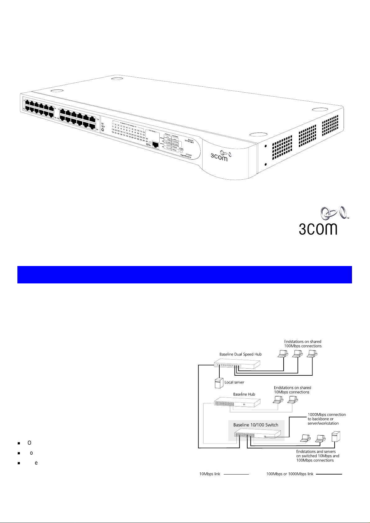
The Baseline 10/100 Switch 24 Port 10BASE-T/100BASE-TX plus
1-Port 1000BASE-T provides high performance switched
connections to 10Mbps and 100Mbps hubs, servers and
workstations that need a dedicated switched link and a switched
fixed speed 1000 Mbps port that can connect to other
1000BASE-T ports or servers/workstations.
The Switch can be powered either from the AC mains supply, or
through an optional 3Com SuperStack 3 Advanced Redundant
Power System (3C16071B). Contact your supplier for details.
1
Page 2

H
OW TO
USE
THE
B
ASELINE
10/100 S
WITCH
24-P
ORT
The nu mbers in this diagra m refe r to num bered s ect ions in t he
text.
Front Panel
1
24 RJ-45 10/100 Ports and 1 RJ-45 1000 Port
WARNING:
sockets. They cannot be used as telephone sockets. Only
connect RJ-45 data connectors to these sockets. Either
shielded or unshielded data cables with shielded or
unshielded jacks can be connected to these data sockets.
AVERTISSEMENT: Les ports RJ-45.
femelles blindées de données RJ-45. Vous ne pouvez pas
les utiliser comme prise de téléphone. Branchez uniquement des connecteurs de données RJ-45 sur ces prises
femelles. Les câbles de données blindés ou non blindés,
avec les jacks blindés ou non blindés, l’un ou l’autre, peuvent être branchés à ces prises de courant de données.
WARNUNG: RJ-45-Anschlüsse.
RJ-45-Datenbuchsen. Sie können nicht als Telefonanschlußbuchsen verwendet werden. An diesen Buchsen
dürfen nur RJ-45-Datenstecker angeschlossen werden.
Diese Datenstecker können entweder mit abgeschirmten
oder unabgeschirmten Datenkabeln mit abgeschirmten
oder unabgeschirmten Klinkensteckern verbunden werden.
10BASE-T/100BASE-TX Po rts
The Baseline 10/100 Switch 24 Port 10BASE-T/100BASE-TX plus
1-Port 1000BASE-T has 24 10/100Mbps auto-negotiating ports.
Ports 1–23 are MDIX ports. Each can be connected to a device
with an MDI port (such as a workstation) using a normal ‘straight
through’ TP (twisted pair) cable. Alternatively, you can connect to
a device with MDIX ports using ‘cross-over’ TP cab le.
Port 24 is ‘switch selectable’ MDI/MDIX us ing the MDI swit ch, as
described in 2. Using this port, you can connect to any other
device withou t the need fo r ‘cross-over’ cab le.
Ports 1 to 24 are auto-negotiating: their speed and duplex mode
(half duplex or full duplex) are automatically determined by the
capabilities of the connected device. Each port can be connected
to either a 10BASE-T or a 100BASE-TX device.
CAUTION:
duplex auto-negotiation. If the connected device does not
!
support auto-negotiation, the Switch will operate in half
duplex mode (even if the device is operating in full duplex
mode). In such a configuration, you may notice some
degradation of network performance. 3Com recommends
that you use devices that are capable of auto-negotiation
(and that you ensure that auto-negotiation is enabled, if
it is a configurable option).
1000BASE-T Port
Port 25 is a 1000BASE-T port capable of auto-negotiation with
the connected port to operate at 1000BASE-T full duplex. It
auto-senses an MDI/MDIX connection and can be used to connect
RJ-45 ports.
The Baseline 10/100 Switch supports full
These are shielded RJ-45 data
Il s’agit de prises
Dies sind abgeschirmte
to either another 1000BASE-T switch port or to a 1000BASE-T
server or workstation without additional configuration.
Connecting to a Netw ork Device
To connect a device to the Baseline 10/100 Switch 24 Port
10BASE-T/100BASE-TX plus 1-Port 1000BASE-T, use Category 5
unshielded or shielded (screened) 100 Ohm TP cable (or
Category 3 cable for a 10Mbps connection). The maximum length
of cable for each connection is 100m (328ft). Connect one end of
the cable to an RJ-45 port on the Baseline 10/100 Switch, and
the other end to the appropriate RJ-45 port on the connecting
device.
Connecting to another Switch or Hub
If you connect two Baseline 10/100 Switch 24 Port
10BASE-T/100BASE-TX plus 1-Port 1000BASE-T units
together, 3Com recommends that you use the
1000BASE-T ports on both units for the link. You must
use Category 5 cable when connecting the units.
1000BASE-T connection:
24 Port 10BASE-T/100BASE-TX plus 1-Port 1000BASE-T to
another Switch using the 1000BASE-T port, use a normal ‘straight
through’ cable and connect each end to the 1000BASE-T port on
each unit.
100BASE-TX connection:
24 Port 10BASE-T/100BASE-TX plus 1-Port 1000BASE-T to a
SuperStack 3 hub using a normal ‘straight through’ cable ,
connect any port on the Baseline 10/100 Switch 24 Port
10BASE-T/100BASE-TX plus 1-Port 1000BASE-T to the MDI/MDIX
port on the hub, as shown below. Ensure that the MDI switch on
the hub is in (MDI).
An alternative method of connecting the Baseline 10/100 Switch
to a hub using a normal ‘straight through’ cable is to connect any
MDIX port on the hub to the MDI/MDIX port on the Baseline
10/100 Switch, ensuring that its MDI Switch is set to in (MDI).
You can us e ‘cross-over’ TP cable to connect any MDIX port on
the Baseline 10/100 Switch to any MDIX port on a hub.
To connect a Baseline 10/100 Switch
To connect the Baseline 10/100 Switch
2
Page 3

2
MDI Switch
This switch affects port 24 only:
Out Port 24 is an MDIX port.
It can be connected to a device with an MDI
MDIX
MDI
3
Display Function Switch
This switch affects the Status LEDs described in 4 and 5:
4
Activity/Duplex Status LEDs
The first (top) and third row of LEDs, which are colored yellow,
show the activity or duplex status of the related ports:
When the Display Function switch is out (its normal position),
these LEDs show the activity of each port. The LED flashes
when packets are received or transmitted on the port.
When the Display Function switch is pressed in, these LEDs
show the duplex status of each port:
On The port is operating in full duplex mode.
Off Ports 1 to 24: If the link is established, the port is
operating in half duplex mode.
Port 25: No link is present.
5
Link/Speed Status LEDs
The second and fourth (bottom) row of Status LEDs, which are
colored green, show the link or speed status of the related ports:
When the Display Function switch is out (its normal position),
these LEDs show the link status of each port:
On The link has been established and the segment
attached to the port is functional.
port (such as a workstation) using a normal
‘straight through’ TP cable.
In Port 24 is an MDI port.
It can be connected to an MDIX port on a
device (such as a hub) using a normal
‘straight through’ TP cable.
Out This is the normal position of the switch.
The Status LEDs show the Activity and Link
Status of each port.
In When the switch is pressed in, the Status
LEDs show the Duplex and Speed Status of
each port. The switch returns to the out position when released. This switch does not
affect port 25.
Off The link has not been established. Either nothing is
connected to the port, or there is a problem:
■
Check that the attached device is powered on.
■
Check that the cable is the correct type and is not faulty.
If the LED is off for port 24, check the setting of the
MDI switc h. Refe r to 2. Try toggling the MDI switch.
If the port is connected to another unit’s MDI/MDIX
port, check the other unit’s MD I swit ch p os ition.
If these checks do not identify the cause of a problem, it may be that the unit or the device connected
to the por t is faulty. Contac t your sup plier for fu rther advice.
When the Display Function switch is pressed in, thes e LED s
show the speed status of each port:
On Ports 1 to 24: The port is operating at 100Mbps.
Port 25: The port is operating at 1000 Mbps
Off Port 1 to 24: If the link is present, ports 1 to 24 are
operating at 10Mbps.
Port 25: The link has not been established.
6
Power/Self Test LED
The Power/Self test LED lights green when the unit is powered on
and ready for use.
Rear Panel Conne ctions
7
Power Supply
The Baseline 10/100 Switch 24 Port 10BASE-T/100BASE-TX plus
1-Port 1000BASE-T automatically adjusts to the supply voltage.
Only use the power cord that is supplied with the unit.
8
Socket for Redundant P ower System (RPS)
Only connect a 3Com SuperStack 3 Advanced RPS (3C16070,
3C16071, 3C16071A or 3C16071B) to this socket. An
appropriate power module and cable is required. The connector
on the Baseline 10/100 Switch 24 Port 10BASE-T/100BASE-TX
plus 1-Port 1000BASE-T is a Type 2 socket. For details, follow the
installation instructions in the guides that accompany the
Advanced RPS and the power module.
9
Self-adhesive Pads
The unit is supplied with four self-adhesive rubber pads.
You do not need to apply the pads if you intend to rack
mount the unit.
If the unit is to be part of a free standing stack, apply the pads to
each marked corner area on the underside of the unit. Place the
unit on top of the lower unit, ensuring that the pads locate with
the rece sses of the lower u nit.
I
NSTALLATION
R
ECOMMENDATIONS
Positioning the Switch
When deciding where to position the Baseline 10/100 Switch 24
Port 10BASE-T/100BASE-TX plus 1-Port 1000BASE-T ensure:
It is accessible and cables can be connected easily.
Cabling is away from sources of electrical noise. These include
lift shafts, microwave ovens, and air conditioning units. Electromagnetic fields can interfere with the signals on copper
cabling and introduce errors, therefore slowing down your
network.
Water or moisture cannot enter the case of the unit.
Air flow around the unit and through the vents in the side of
the case is not restricted (3Com recommend that you provide
a minimum of 25mm (1in.) clearance).
The air is as free from dust as possible.
Temperature operating limits are not likely to be exceeded. It
is recommended that the unit is installed in a clean, air conditioned environment.
It is always good practice to wear an anti-static wrist
strap when installing network equipment, connected to a
ground point. If one is not available, try to keep in contact with a grounded rack and avoid touching the unit's
ports and connectors, if possible. Static discharge can
cause reliability problems in your equipment.
Rack Mounting or Free Standing
The unit can be mounted in a 19-inch equipment rack using the
Mounting Kit. Refer to “Mounting Kit Instructions” on page 4, or
it can be free standing. Do not place objects on top of the unit or
stack.
CAUTION: If installing the Baseline 10/100 Switch 24
Port 10BASE-T/100BASE-TX plus 1-Port 1000BASE-T in a
free standing stack of different size SuperStack 3 units,
the smaller units must be installed above the larger ones.
Do not have a free standing stack of more than six units.
3
Page 4

Power Supp ly
Power problems can be the cause of serious failures and downtime in your network. Ensure that the power input to your system
is clean and free from sags and surges to avoid unforeseen network outages. We recommend that you install power conditioning, especially in areas prone to black outs, power dips and
electrical storms.
The unit is intended to be grounded. Ensure it is connected to
earth ground during normal use. Installing proper grounding helps
to avoid damage from lightning and power surges.
Power Up
Use the following sequence to power up the Baseline 10/100
Switch 24 Port 10BASE-T/100BASE-TX plus 1-Port 1000BASE-T:
Check the network connections and cables.
Connect the power supply cable to the appropriate power
socket on the rear panel of the unit; refer to 7 or 8.
Connect the plug to the power supply outlet socket and
switch on the power supply at the socket. If you are using
the Advanced Redundant Power System, ensure it is powered on.
When the switch is powered on, the Power/Self Test LED should
first flash green, then stay lit. If it does not, refer to 6.
Spot Checks
At frequent intervals you should visually check the Baseline
10/100 Switch 24 Port 10BASE-T/100BASE-TX plus 1-Port
1000BASE-T. Regular checks can give you an early warning of a
possible failure; any problems can then be attended to when
there will be least effect on users. Check the following:
Cabling Check that all external cabling connections are
secure and that no cables are pulled taut.
Cooling fans Where possible, check that the cooling fans are
operating by listening to the unit. The fans are
fitted near to the front right hand side of the
unit (when viewed from the front).
If you experience any problems operating the Baseline 10/100 Switch 24 Port 10BASE-T/100BASE-TX plus 1-Port 1000BASE-T, refer to “Problem Solving” on page 4.
M
OUNTING
KIT I
NSTRUCTIONS
Introduction
The Baseline 10/100 Switch 24 Port 10BASE-T/100BASE-TX plus
1-Port 1000BASE-T is supplied with two mounting brackets and
four screws. These are used for rack mounting the unit. When
mounting the unit, you should take note of the guidelines given
in “Positioning the Switch” on page 3.
Rack Mount ing the U nits
The Baseline 10/100 Switch is 1U high and will fit a standard
19-inch rack.
CAUTION: Disconnect all cables from the unit before
continuing. Remove the self-adhesive pads from the
underside of unit, if already fitted.
1
Place the unit the right way up on a hard, flat surface with
the front facing towards you.
2
Locate a mounting bracket over the mounting holes on one
side of the unit.
P
ROBLEM
Refer to the information about LEDs given earlier in this guide to
see if the problem can be identified and rectified. Here are some
common problems that can occur:
Link Status LED not lit for a port that has a connection.
There is a problem with this connection. Check that:
The device being connected to is powered on and operating
correctly.
The cable is connected at both ends.
That you are using a TP cable that is:
■
‘Straight through’, to connect an MDIX port to an MDI
port.
■
‘Cross-over’, to connect an MDIX port to an MDIX port,
or an MDI port to an MDI port.
The cable is not damaged.
If the connection is to a workstation, that the workstation’s
network interface is installed and configured correctly.
S
OLVING
3
Insert the two screws supplied in the mounting kit and fully
tighten with a suitable screwdriver.
4
Repeat the two previous steps for the other side of the unit.
5
Insert the u nit int o the 19 -inc h rack a nd se cure with suita ble
screws (not provided).
6
Reconnect all cables.
at a time, waiting a few seconds between each port. If the LEDs
go off after removing a port connection, the device that was
connected to that port is introducing an excessive amount of
broadcast frames to the network (some pieces of network
equipment operate by sending out broadcast frames regularly).
Refer t o the docum enta tion t hat a ccomp anies the dev ice fo r
information on disabling the broadcast operation.
If the problem persists and the unit still does not operate
successfully, contact your supplier with the following information
before returning the unit:
Product number and serial number (printed on a label supplied with the unit)
A brief description of the fault
All Activity LEDs appear to be lit continually.
broadcast storms on the network. Remove port connections one
There may be
4
Page 5

S
AFETY INFORMATION
Please read the following safety information carefully before
installing the Baseline 10/100 Switch 24 Port 10BASE-T/100BASE-TX
plus 1-Port 1000BASE-T.
WARNING:
by qualif ied personn el only.
If installing the Switch unit in a stack with SuperStack 3 Hub units, the
Baseline 10/100 Switch 24 Port 10BASE-T/100BASE-TX plus 1-Port
1000BAS E-T unit m ust be ins talled be low the n arrower Hub u nits.
The unit must be connected to an earthed (grounded) outlet to comply
with int ernat ional sa fety sta ndards.
Do not connect the unit to an A.C. outlet (power supply) without an
earth (g round) co nnection .
The appli ance cou pler (the connecto r to the unit and not the wa ll plug)
must have a configur ation for matin g with an EN60320 /IEC320
appliance inlet.
The sock et outlet must be ne ar to the unit and ea sily acce ssible . You
can only remove pow er from th e unit by disc onnec ting the po wer cord
from the ou tlet.
This u nit op erat es under SELV (Saf ety Ex tra L ow Volt age) c ond ition s
according to IEC 60. The conditions are only maintained if the
equipme nt to wh ic h it is conn ect ed a lso ope rate s under SELV condi tion s.
Only c onn ect an Advance d Redunda nt Powe r System ( 3C1607 0,
3C16071 , 3C160 71A or 3C16 071B) or Redundant Power System
(3C565047) to the Redundant Power Syst em socket.
France and Peru onl y
This unit cannot be powered from IT
Installation and removal of the unit must be carried out
†
supplies. If you r supplies are of IT type, thi s
unit must be power ed by 230V ( 2P+T) via an is olat ion transfor me r ratio 1:1, with the
secondary conne ction poin t labelled Ne utral, conne cted directly t o earth (grou nd).
†
Impédance à la terre
Power Cord Set
This must be appro ved for the country wh ere it will be us ed. e.g.
U.S.A . an d
Canada
Denmark
Switzerland
UK
Europe
The cord set must b e UL-appr oved an d CSA ce rtified .
■
The minimum specifications for the flexible cord are:
■
No. 18 AWG
Type SV or SJ
3-conductor
The cord set must have a rated current capacity of at least
■
10A.
The atta chment plu g must be an earth -grou nding type
■
with a NEM A 5-15P (15 A, 125V) or NEMA 6- 15P (15A,
250V) conf igurat ion.
The suppl y plug mu st compl y with Sect ion 107- 2-D1,
■
Standard DK2-1a or DK2-5a.
The suppl y plug mu st compl y with SEV/A SE 1011.
■
The suppl y plug mus t co mply wit h BS1 36 3 (3- pin 13-a mp)
■
and be fitted with a 5A fuse which complies with BS1362.
The mains cord must be <HAR> or <BASEC> marked and
■
be of type HO3VVF3 GO.75 (m inimum) .
The suppl y plug mu st compl y with CEE7/ 7 (“SCHUKO”)
■
The mains cord must be <HAR> or <BASEC> marked and
■
be of type HO3VVF3 GO.75 (m inimum) .
L’
INFORMATION DE
S
ÉCURITÉ IMPORTANTE
Veuillez lire à fond l'in format ion d e la sécurité su ivant e avant
d'inst aller le Base line 10 /100 Swit ch 24 Por t 10BAS E-T/10 0BASE -TX
plus 1-Port 1000BASE-T.
AVERTISSEMENT:
être confi és à un personnel q ualifié.
Si vous entassez l’unité Switch avec les unités SuperSta ck 3 Hu b, l’unité
Baseline 10/100 Switch 24 Port 10BASE-T/100BASE-TX plus 1-Port
1000BAS E-T doit être install ée en dessous des unités Hub plus étroites.
Ne branch ez pas v otre appa reil sur une prise se cteur (a liment ation
électriqu e) lors qu'il n'y a pas de conn exion de mise à la te rre (mise à la
masse).
Vous devez ra ccorder ce gro upe à une sortie mise à la terre (mise à la
masse) afin de respecter le s normes inter nationales de sécurité.
Le coupleur d’appareil (le con necteu r du group e et non pas la prise
murale) doit resp ecter u ne config uratio n qui perm et un bra nchemen t
sur une entrée d’appareil EN 60320/IE C 320.
La pris e secteu r doit se trouver à prox imité de l’appareil et son accès
doit être facile. Vous ne p ouvez m ettre l’ap pareil ho rs circuit qu ’en
débrancha nt son co rdon él ectr ique a u niv eau de cet te pr ise.
L’appareil fonctionne à une tension extrêmement basse de sécurité qui
est conforme à la norm e IEC6 0950. Ces c onditio ns ne son t mainte nues
que si l’équipement auquel il est raccordé fonctionne dans le s mêmes
conditions.
Branchez uniquement un Advanced Redu ndant Po wer Syst em
(3C160 70, 3C16071, 3C16071A ou 3C16071B) ou un Redundant Power
System ( 3C56504 7) sur la prise femelle du Redundant Power System.
W
ICHTIGE
L’installation et la dépose de ce gro upe doive nt
S
ICHERHEITSINFORMATIONEN
France et Pérou uniquement:
Ce groupe ne peut pas être alim enté par un dispositif à impédance à la te rre . Si vo s
alimentation s sont du type impédance à la terre, ce groupe doit être alimenté par
une tension de 230 V (2 P+T ) par le b iais d’un transformateur d’isolement à rapport
1:1, avec un point secondai re de connex ion portant l’a ppellation Ne utre et avec
raccordement direct à l a t erre (ma ss e).
Cordon électrique
Il doit être agréé da ns le pays d ’utilisation.
Etats-U nis et
Canada:
Danemark:
Suisse:
Europe
■
Le cordon doit a voir reçu l’hom ologatio n des UL et un
certificat de la CSA.
■
Le cordon soupl e doit res pecter, à titre minimum, les
spécifications suivantes:
calibre 18 AW G
type SV ou SJ
à 3 conducteurs
■
Le cordon doit être en m esu re d’ac heminer un co urant
nominal d’au mo ins 10 A .
■
La prise femel le de branche ment doit êt re du type à mise à la
terre (mise à la ma ss e) et resp ect er l a con fig urat ion N EMA
5-15P (15 A, 1 25 V) ou NE MA 6-15P (15 A, 250 V).
■
La prise mâle d’alimenta tion doit respe cter la sec tion 107 -2 D1
de la norme DK2 1a ou DK2 5a.
■
La prise mâle d’alimentation doit respecter la norme SEV/ASE
1011.
■
La prise secteur doit être conforme aux normes CEE 7/7
(“SCHUKO”)
■
LE cordon sect eur doit porter la mention < HAR> ou <BA SEC>
et doit être de type HO3VVF3GO.75 (minimu m).
Bitte unb eding t vor dem Einbau en des Bas elin e 10/10 0 Switch 24
Port 1 0BA SE-T/ 100 BAS E-TX plu s 1 -Po rt 1 000B ASE -T Ei nhe it die
folgenden Sicherheitsanweisungen durchlesen.
WARNUNG:
durch Fa chperso nal erfol gen.
Wenn die B aseline 10/ 100 Swi tch 24 Po rt 10BAS E-T/100B ASE-T X plus
1-Port 1000BASE-T Einheit in einer Stapel mit anderen SuperStack 3
Hub Einheiten eingebaut werden soll, muß die Basel ine 10/10 0 Switch
24 Port 1 0BASE -T /100B ASE -TX pl us 1-P ort 1000BA SE- T Ei nheit un te r die
schmaleren Hub Einheiten eingebaut werden.
Das Gerät nicht an ein e Wechse lstromst eckdos e ansch ließen, die nicht
geerdet i st.
Das Gerät muß an eine ge erdete Ste ckdose an geschlos sen werde n, die
die int ern at ional en Sic herh eit sno rmen er füllt.
Der Gerätestecker (der Anschluß an das G erät, nicht d er
Wandsteckdosenstecker) muß eine pas sende K onfigurat ion für ei nen
Geräteeingang ge mäß EN60320/ IEC320 ha ben.
Die Install ation un d der Aus bau des Geräts da rf nur
Stromkabel
Schweiz
Europe
5
Die Netzsteckdose muß in der Nähe des Geräts und leicht zugänglich
sein. Die Stromver sorgun g des Geräts kann nur du rch Heraus ziehe n des
Gerätene tzkabel s aus d er Netzst eckdos e unterbro chen we rden.
Der Betrieb dieses Geräts erfolgt un ter den SELV-Bedingungen
(Sicherheitskleinst spannung) ge mäß IEC 60. Diese B edingungen sind nur
gegeben, wenn auc h die an d as Gerät angesc hlossenen Ge räte unter
SELV- Bedingunge n betrieb en werden.
Advanced Redundant Power Syste m (3C16070, 3C 16071,3C16 071A
Nur ein
3C16071B)
oder
Redundant Power System
. Dies muss von dem Land, in dem es be nutzt wird gepr üft werden:
Dies er St roms tecke r muß die SEV/ASE 10 11Besti mmunge n
■
einhalten.
■
Das Netzkabel muß vom Typ HO3VVF3GO.75
(Mindestanforde rung) sein und die Aufs chrift <HAR> oder
<BASEC> tragen.
■
Der Netzstecker muß die Norm CEE 7/7 e rfüllen (”SCHUKO”).
Redundant Power Syst em (3C565 047)
oder
Anschluß anschließen.
an den
Page 6

T
ECHNICAL INFORMATION
Related Standards
The SuperStack 3 Baseline 10/100 Switch 24 Port
10BASE-T/100BASE-TX plus 1-Port 1000BASE-T has been
designed to the following standards:
Functional
Safety
EMC Emissions
Immunity
Environmental
Operating Temperature
Humidity
Standard
L
IMITED
This wa rra nty app lies to cu sto mers loca ted in th e Uni ted Stat es , Au strali a , Canad a
(except Quebec), Ireland, New Zealand, U.K., and ot her Engli sh language cou ntries,
and countries for which a tr anslation int o the loca l language i s not provided.
SuperStack 3 Base line 10/100 Sw itch 24- Port 10BASE- T/100BASE- TX plus
1-Port 1000BASE-T (3C16467)
HARDWARE:
product will be free from de fects in w orkmansh ip and mate rials, under no rmal use
and service, for t he follow ing length of time from the date of pu rchase from 3Com
or its a utho rize d rese ller :
Lifetime, for as l ong as the or iginal Cust omer owns t he product (not transfera ble to
a subsequent end us er)
3Com's sole oblig ation under this express war ranty shall be , at 3Com' s option a nd
expense, to repair the defective p roduct or par t, deliver to C ustomer a n equivalent
product or part to repla ce the defec tive item, or if neither of the tw o foregoing
options is reasonably a vailabl e, 3Com may, in its sole di scretion, refund to C ustomer
the purchase price paid for the d efective pr oduct. All p roducts that are replac ed will
become the property of 3Com. Re placement products or part s may be ne w or
reconditioned. 3Com w arrants an y replaced or repa ired product or pa rt for ni nety
(90) days from shipm ent, or the re mainder of the i nitial warra nty peri od, whichever
is lon ger.
SOFTWARE:
it, except as no ted below, will perform i n substa ntial confor mance to its program
specifications, for a period of ninety (90) days from the date of purchase from 3Com
or its authorized rese ller. 3Com warrants the me dia conta ining software a gainst
failure during the wa rranty peri od. No updat es are provided, u nless specif ically
included in the Included Ser vices section. 3Com's so le obligation under this e xpress
warranty shall be , at 3Com's opt ion and e xpense, to refund the purchase price paid
by Customer for a ny defect ive software prod uct, or to replace any defe ctive med ia
with software which substantia lly confor ms to applica ble 3Com pu blished
specifications. Customer assumes responsibility for the selection of the appro priate
applications progr am and assoc iated reference ma terials. 3C om makes n o warranty
or representation that its softwa re products will mee t Customer's requirements or
work in combina tion with any ha rdware or appl ications sof tware products provided
by third parties, that the oper ation of the sof tware products will be uninterrupted or
error free, or that all defects in the software products will be correcte d. For any third
party products liste d in the 3Com s oftwa re product documen tation or spe cifications
as being compati ble, 3Com wi ll make reaso nable efforts t o provide compa tibility,
except where the non- compatibi lity is cause d by a "b ug" or defect in the thi rd
party's product or f rom use of the s oftware product not in acco rdance with 3Com 's
published specifica tions or user manua l.
THIS 3C OM PROD UCT M AY INCLUDE OR BE BUND LED WI TH ( 1) THI RD PARTY
SOFTWARE, OR (2 ) 3 COM S OFTWARE THAT IS LICE NS ED "A S IS" , TH E U SE OF
WHICH IS GOVERNED BY A SEPARATE END USER LICENSE AGREEMENT. THIS 3COM
WARRANTY DOES NOT APP LY TO SUCH THIRD PARTY SOFTWARE OR 3COM
SOFTWARE LICENSED "A S IS". FOR T HE APPLICA BLE WARRANTY, PLEASE REFER TO
THE END US ER LICEN SE AG REEM ENT GOVE RNI NG TH E USE OF SUCH SOFTWARE OR
THE ACCO MPANYING DOCUM ENTATION RELATING TO SUCH SOFTWARE.
YEAR 2000 WARRANTY:
Warranty stated above, 3Com warra nts that ea ch product sold or licensed to
Customer on an d after January 1, 1998 tha t is date se nsitive wi ll continue
performing properl y with regard to such d ate data on and af ter January 1, 2000,
provided that all ot her products us ed by Custo mer in conn ection or c ombination
with the 3Com produ ct, including ha rdware, software, and f irmware, accurat ely
exchange date dat a with the 3C om product, w ith the exce ption of those products
identified at 3Co m's Web site, http:/ /www.3com.com/products/yr 2000.html, a s not
3Com warrants to Customer that each software program licensed from
ISO 8802-3, IEEE 802.3 (Et hernet), IEEE 802.3u
(Fast Ethernet), IEEE 802.3ab (Gigabit Ethernet) IEEE 802.3x (Flow Control) IEEE 802.1D
1998 (Bridging)
UL 1950, EN 60950, CSA 22.2 #950, IEC
60950
EN 55022 Class A, FCC Part 15 Subpart B
Class A, ICES-003 Class A, VCCI Class A,
AS/NZS 3548 Class A, CNS 13438 Class A
EN 55024
0–50 °C (32–122°F)
10–95% (non-condensing)
EN 60068 (IEC 68)—various parts
W
3Com warrants to the end u ser ("Custom er") that thi s hardware
In addition to the Hardware Warranty and Software
ARRANTY
Physical
Width
Depth
Height
Weight
Mounting
440mm (17.3in.)
235mm (9 .3in.)
44mm (1.7in.) or 1U
2.6kg (5.8lb)
Free standing, or 19in. rack mounted using
the mounting kit supplied
Electrical
Power In let
AC Line Frequency
Input Voltage
Current Rating
Maximum Power
Consumption
Maximum Power
Dissipation
meeting this sta ndard. If it ap pears that a ny product th at is stated t o meet thi s
standard does not perform prope rly with regard t o such date data on and a fter
January 1, 2000, and Custo mer notifies 3Com wi thin ninety (90) days after purchase
of the product from 3C om or its authorized reseller, 3Com shall, at its op tion and
expense, provide a software up date which woul d effect the p roper perfor mance of
such product, repair such product, de liver to Cu stomer an e quivalen t product to
replace such product, or if none of the foregoing is feasibl e, refund to Customer t he
purchase price p aid for such p roduct.
Any software u pdate or r eplaced or repaired product w ill ca rry a Year 2000 Warranty
for ninety (90) days after purchase.
OBTAINING WARRANTY SERVICE:
Service Center or an Authorized 3Com Service Center within the applicable warranty
period to o btain war ranty serv ice a uthor iza tion. Dat ed proo f of pu rchase from 3Com
or its authoriz ed reseller may b e required. Products r eturned to 3 Com's Co rporate
Service Cente r must be pre-aut horized by 3 Com with a U ser Service Or der (USO)
number (or a Return Material Authorization (RMA) number or a Service Repair Order
(SRO) number, whichever was issue d) marked on the outside of the pack age, and
sent prepaid and packaged appr opriately for s afe ship ment, and it is recommende d
that they be in sured or sent by a method t hat provides for tracking of the pac kage.
Responsibility for loss or da mage doe s not trans fer to 3Co m until the returned item
is received by 3C om. The repaired or replaced item wi ll be shipped to Customer, at
3Com's expens e, not later than thirty (3 0) days afte r 3Com receives t he defectiv e
product, and 3Com w ill retain ris k of loss or damage un til the ite m is deliv ered to
Customer.
3Com shall not be responsibl e for any soft ware, firmware, i nformation, or memory
data of Custome r containe d in, stored on, or integrat ed with any products return ed
to 3Com for repa ir, whether under warranty or not .
Dead- or Defective-on-Arrival
or exhibits a de fect in m aterials or w orkmanship within the f irst forty- eight (48)
hours of instal lat ion but no later than thirt y (30) days aft er the date of p urchase , an d
this is verified by 3Com, it will be considered dead- or defective -on-arrival (DOA) and
a replacement shal l be provided pr ior to 3Com receiving the defective product, but
only if Custom er provides a purchase order num ber, credit card number, or other
method of payme nt acceptab le to 3Co m, to be used i f 3Com needs to charge
Customer for the replacement, as explained below. The replacement product will
normally be sh ipped not late r than three (3) business da ys after 3C om's verifi cation
of the DOA produc t, but may be delayed due to expor t or import pr ocedures. The
shipment of a repla cement produc t prior to 3C om receivi ng the defec tive product is
subject to loca l legal requirement s and may no t be avai lable in all locations. Whe n
such a replacement is provided an d Custome r fails to retu rn the or iginal product to
3Com within fif teen (15) da ys after s hipment o f the replacement , 3Com wi ll charge
Customer for the replacement pr oduct, at lis t price.
Shipment of a R eplacement P rior to 3C om Receiving the Defective Product
provided for five (5) years, after which time it may be available for a specified fee,
but in either case only if C ustomer provides a purchase order number, credit card
number, or other method of payme nt acceptab le to 3Co m, to be used i f 3Com
needs to charge Customer for the replacement, as explained below. 3Com will make
commercially reasonable efforts to ship the replacement product not later than five
(5) business days after receiv ing the request f or a replaceme nt, but ma y be delayed
due to product a vailability or export or i mport procedures. The shipment of a
replacement product prior to 3Com receiving the defective product is subject to local
legal requirements a nd may not be available in all locati ons. When su ch a
replacement is p rovided and Custom er fails to return th e origin al product to 3 Com
within fifteen (15) days after shipment of the replacement, 3Com will charge
Customer for the replacement, at list price. This replacement prior to 3Com receiving
IEC 320
50/60 Hz
100–240 VAC
1 Amps (maximum)
42 VA
142 BT U/hr
Customer must contact a 3Com Corporate
. In the event a p roduct comple tely fails t o function
is
6
Page 7

the defective produc t is different from t he fee-base d Advance Ha rdware
Replacement Service, which is available as a contracted service offering.
INCLUDED SERVICES:
3Com's Electronic S upport Servi ces
Knowledgebase, information on known bugs , documenta tion, release not es, and
publicly availab le software and firmware upgra des. 3Com reser ves the righ t to
modify or cancel thi s offering at any time , without adv ance notic e.
Telephone Technical Support
be provided at no additional charge for 1 2 mo nths from t he date of purchase, on a
commercially reasonable efforts bas is. Telephone support is provided b y 3Com onl y
if Customer purchase d this produc t directly from 3Com , or if Cu stomer's reseller is
unable to provide t elephone supp ort. To qualify for this telep hone techni cal
support, Custom er must registe r on the 3Com Web site at
http://support.3Com .com/inde x.htm, and sta te the date of purchase, pro duct
number, and serial number. 3Com's response to a reque st for tel ephone techni cal
support will be in the form of a return call from a 3Com r epresentativ e by close of
business the follow ing busine ss day, defined as 9 a.m. to 5 p .m., local time,
Monday through Fr iday, excluding local holidays. Please refer to the Technical
Support append ix in the Use r Guide for telephone numbers.
Software U pdate s
this product down loaded through th e 3Com Sof tware Library.
WARRANTIES EXCLUSIVE
WARRANTED ABOVE, CUST OMER'S SOLE RE MEDY FOR BRE ACH OF THAT
WARRANTY SHALL BE REPAIR, REPLACEMENT, OR REFUND OF THE PURCHASE
PRICE PAID, AT 3COM 'S O PTION . T O THE F UL L EXT ENT A LL OWED B Y LAW, THE
FOREGOIN G WARRAN TIES AND RE MEDIE S ARE EXC LUSIVE A ND AR E IN L IEU OF
ALL OTHER WARRANTIES, TERMS, OR CONDITIONS, EXPRESS OR IMPLIED, EITHER
IN FACT OR BY OPERATION OF LAW, STATUTORY OR OTHERWISE, INCLUDING
WARRANTIES, TERMS, OR CONDITIONS OF MERCHANTABILITY, FITNESS FOR A
PARTICULAR PU RPOS E, SATISFACTOR Y QUA LITY, CORRESP ONDENC E WIT H
DESCRIPT ION , AND N ON-IN FRIN GEME NT, ALL OF WHI CH ARE EXP RESSLY
DISCLAIMED. 3COM NEITHER ASSUMES NOR AUTHORIZES ANY OTHER PERSON TO
ASSUME F OR IT ANY OTHER L IABI LIT Y IN CO NNE CTION WITH THE S ALE,
INSTALLATION, MAIN TE NANCE OR U SE O F I TS PR ODUC TS.
3COM SHA LL NOT BE L IABL E UND ER TH IS WARRAN TY I F ITS T ESTING AND
EXAMINATION DISCLOSE THAT THE ALLEGED DEFECT OR MALFUNCTION IN THE
PRODUCT DOES NOT EXIST OR WAS CAUSED BY CUSTOMER'S OR ANY THIRD
PERSON'S MISUSE, NEGLECT, IMPROPER INSTALLATION OR TESTING,
, All software and firmware upgrades and the latest code for
: IF A 3COM PRODUCT DOES NOT OPERATE AS
, available at no c harge, include 3Com
, with coverage f or basic trouble shooting o nly, will
UNAUTHORIZED ATTEMPTS TO OPEN, REPAIR OR MODIFY THE PRODUCT, OR ANY
OTHER CA USE B EYOND THE RANGE O F THE INT ENDED US E, O R BY A CCIDE NT,
FIRE, LIGHTNING, POWER CUTS OR OUTAGES, OTHER HAZARDS, OR ACTS OF
GOD.
LIMITATION OF LIABILITY
EXCLUD ES F OR I TSEL F AN D IT S SUP PLI ERS A NY L IABIL ITY, WHETHE R BA SED I N
CONTRACT OR T ORT (I NCLU DING N EGLI GENCE ), FOR INC IDENTAL,
CONSEQUE NTIA L, IN DIRE CT, SPECIAL, OR PUNI TIV E DAMA GES OF AN Y KIND , OR
FOR LOSS OF REVENUE OR PROFITS, LOSS OF BUSINESS, LOSS OF INFORMATION
OR DATA, OR OTHER FINANCIAL LOSS ARISING OUT OF OR IN CONNECTION WITH
THE SALE, INSTALLATION, MAINTENANCE, USE, PERFORMANCE, FAILURE, OR
INTERRUPTION OF ITS PRODUCTS, EVEN IF 3COM OR ITS AUTHORIZED RESELLER
HAS BEEN ADVISED OF THE POSSIBILITY OF SUCH DAMAGES, AND LIMITS ITS
LIABILITY TO REPAIR, REPLACEMENT, OR REFUND OF THE PURCHASE PRICE PAID,
AT 3COM'S OP TIO N. THIS DISC LAI MER OF LI ABIL ITY FOR D AMAG ES WILL N OT BE
AFFECTED IF ANY REMEDY PROVIDED HEREIN SHALL FAIL OF ITS ESSENTIAL
PURPOSE.
DISCLAIMER:
limitation of implied warran ties or t he limitatio n of incident al or conseque ntial
damages for c erta in products s upplie d to c onsu mers, or t he l im itatio n o f li abilit y f or
personal injury, so the above lim itations and exclusio ns may be limi ted in thei r
application to you. When the implied wa rranties are n ot allowed to be excluded in
their entirety, they will be l imit ed to the duratio n of the appl icab le w ritten w arran ty.
This warranty give s you spe cific legal rights whic h may vary de pending on l ocal law.
GOVERNING LAW:
State of California, U.S.A., and by the laws of the United States, excluding their
conflicts of law s principles . The Unite d Nations Co nvention on Contracts for the
International Sale of Goo ds i s he reby e xcluded i n i ts en tirety from appli catio n to t hi s
Limited Warranty.
3Com Corporation
5400 Bayfront Plaza
P.O. B ox 5814 5
Santa Clara, CA 95052-8145
(408) 326-5000
August 2000
3Com reserves the right to modify or cancel this offering at any time, without
advance notice. T his offering i s not availa ble where prohibit ed or restric ted by law.
Some countri es, states, or provinces do not allow the exclusion or
: TO THE FULL EXTENT ALLOWED BY LAW, 3COM ALSO
This Limited Warranty shall be governed by the laws of the
R
EGULATORY
N
OTICES
FCC Statement
This equipment ha s been test ed and found to compl y with the l imits for a Class A
digital device, pur suant to pa rt 15 of t he FCC rules . These limi ts are designe d to
provide reasonable protect ion against harmful int erference wh en the equip ment is
operated in a comm ercial environ ment. This e quipment generates, us es and can
radiate radio fre quency energy and, i f not in stalle d and us ed in accordance wit h the
instructions, may cause harmful interference to radio com munications. Opera tion of
this equipment in a residential area is likely to cause harmful interference to radio
communications , in which ca se the user w ill be required t o correct the int erference
at their own expen se.
Information To The User
If this equipme nt doe s ca use i nter ference to r adio or televis ion receptio n, whi ch c an
be determined by t urning the equipme nt off and on, the user is encouraged t o try
to correct the interference by one or more of the following measures:
■
Reorient the receiving antenn a.
■
Rel ocat e th e e qui pm ent wi th res pec t t o t he re ce ive r.
■
Move the equipment away from the receiver.
■
Plug the equipment into a different outlet so that equipment and receiver are on
different branch circuits.
If necessary, the user should cons ult the dea ler or an experienced radio/televis ion
technician for ad ditional sug gestions. Th e user may f ind the fol lowing bookle t
prepared by the Federa l Communica tions Co mmission help ful:
How to Identify and Resolve Ra dio-TV Inte rference Problems
This booklet is av ailable from the U.S. Gov ernment Printing Office, Wash ington,
DC 20402, Stock No . 004-000-0 0345-4.
P
RODUCTS
The SuperStack 3 Ba selin e 10/ 100 Switch 24 Po rt 10B ASE-T/1 00BA SE-TX plu s 1-Po rt
1000BASE-T is part of the ext ensive Su perStack 3 range of 3Com pr oducts. Thi s
range includes hubs , switche s, power syst ems and othe r networki ng equipme nt,
and is continual ly being dev eloped. Conta ct your sup plier for t he latest prod uct
information and to order these pro ducts.
Product Registration
You can now register your SuperStack 3 Switch on t he 3Com w eb site t o receive
up-to-date informa tion on y our product:
http://www.support.3com.com/warrantyregistration/register.pl
Year 2000 Compliance
For information o n Year 2000 compliance and 3Com p roducts, visi t the 3Com Year
2000 Web page:
http://www.3com.com/products/yr2000.html
Feedback
Your suggestions are very important to us. They will help m ake our docume ntation
more useful to you. P lease e-mai l comment s about this document t o 3Com at :
In order to meet FCC emission s limits, this equipment mu st be use d only w ith
cables which compl y with IEE E 802.3.
CE Statement (Europe)
This product comp lies wit h the E uropea n Low Voltag e Di rective 73 /23/E EC a nd ETIC
Directive 89/336/EE C as amended by European Di rective 93/68/E EC/.
CSA Statement
This Class A d igital appar atus meets a ll requirements of the Cana dian
Interference-Causing E quipment Regulation s.
Cet appareil numér iqu e de l a cl asse A res pec te to ute s les exi gen ces du Règlement
sur le mat ériel brouil leur du Canada .
VCCI Statement
BSMI Statement
pddtechpubs_comments@3Com.com
Please include the following information when commenting: the document title,
part number (shown at the bottom of page 8), and pag e number, if appropriate.
Environmental Statement
It is the poli cy of 3Co m C orporat ion t o be e nviro nmentall y-frie ndly in al l ope rat ions.
To uphold ou r policy, we are committed to:
■
Establishing e nvironmental performan ce standards th at comply w ith national
legislation a nd regulations.
■
Conserving ene rgy, materials and natural resources in all operations.
■
Reducing the w aste genera ted by al l operations.
■
Ensuring that all waste conf orms to recognized env ironmental st andards.
■
Maximizing the recyclable and reusable content of all products.
■
Ensuring that all products ca n be recycled , reused and di sposed of safely.
■
Ensuring that all products a re labelled ac cording to recogni zed environment al
standards.
■
Improving our en vironmental record on a contin ual basis.
7
Page 8

T
ECHNICAL
. The following numbers may be used for technical support:
S
UPPORT
The following numbers may be used for technical support:
Country Telephone Number Country Telephone Number
Asia, Pacific Rim
Australia
Hong Kong
India
Indonesia
Japan
Malaysia
New Ze aland
Pakistan
Philippines
Europe
From anywhere in Europe, call: +31 (0)30 6029900 phone
Euro pe, So uth A fr ic a, an d Mid d le East :
Austria
Belgium
Denmark
Finland
France
Germany
Hungary
Ireland
Israel
Italy
Latin America
Argentina
Brazil
Chile
Colombia
North America
1 800 678 515
800 933 48 6
+61 2 9937 5085
001 800 61 00 9
0031 61 64 39
1800 801 7 77
0800 446 3 98
+61 2 9937 5085
1235 61 26 6 2 602
+31 (0)30 6054396 fax
From the following countries, you may use the toll-free numbers:
0800 297468
0800 71429
800 17309
0800 113153
0800 917959
0800 1821502
00800 12813
1800 553117
1800 9453794
1678 79489
AT&T +800 666 5065
0800 13 32 66
1230 020 0 645
98012 2127
1 800 876-3266
P.R. of China
Singapore
S. Korea
From anywhere in S. Korea:
From Seoul:
Ta iwan, R.O.C.
Thailand
Netherlands
Norway
Poland
Portugal
South Africa
Spain
Sweden
Switzerland
U.K.
Mexico
Peru
Puerto R ico
Venezuela
10800 61 00137 or
021 6350 1590
800 6161 463
00798 611 2230
(0)2 3455 6455
0080 611 261
001 800 611 2000
0800 0227788
800 11376
00800 3111206
0800 831416
0800 995014
900 983125
020 795482
0800 55 3072
0800 966197
01 800 CARE (01 800 2273)
AT&T +800 666 5065
800 666 5065
AT&T +800 666 5065
L
EGAL
© 3Com Technologies, 2000.
may be reproduced in an y form or by any means or used t o make any derivative
work (such as transl ation, tr ansformation , or adaptati on) without permission from
3Com Technologies.
3Com Technologies reserves the right t o revise this doc umentation a nd to m ake
changes in cont ent from time t o time without obligat ion on the pa rt of 3Com
Technologies to provide notif ication of s uch revision o r change.
3Com Technologies provides this document ation withou t warra nty of any kind ,
either implied or expressed, in cluding, but not limited t o, the imp lied warranti es of
merchantability and f itne ss fo r a pa rtic ular p urpose . 3Com ma y ma ke im prove ments
or changes in the product( s) and/or the program(s) des cribed in this doc umentati on
at any time .
UNITED STATES GO VERNMENT LEGENDS:
If you are a Unite d S tates gov er nme nt a gency, th en thi s d ocum ent atio n an d th e
software described he rein are provided to you subjec t to the fol lowing restric ted
rights:
For units of the D epartm ent of Defe nse:
Restricted Rights Le gend:
subject to restrictio ns as set forth i n subparagr aph (c) (1) (ii) for restri cted Rights i n
Technical Data a nd Compute r Software cla use at 48 C.F.R. 52.227-7013. 3Com
Centre, Boundary Way, Maylands Park South, H emel Hempst ead, Herts, H P2 7YU,
U.K.
N
OTICES
All rights reserve d. No part of this docum entation
Use, duplicat ion or disclosu re by the Gove rnment i s
For civilian agencie s:
Restricted Rights Le ge nd:
forth in subpar agraph (a) throug h (d) of the Co mmercial Compu ter Softwa re Restricted Rights Clause at 48 C.F.R. 52.227-19 and the limit ations set f orth in
3Com Corporation ’s standard commercial agreement for the software. Unpublished
rights reserved unde r the cop yright laws of the United S tates.
If there is any sof tware on removab le media de scribed in t his document ation, it is
furnished un der a licens e agreement inc luded with the product a s a separate
document, in the hard copy d ocumentation , or on the removable me dia in a
directory file named LICENSE.TXT. If you are unable to locate a copy, please contact
3Com and a copy w ill be p rovided to you.
Unless otherwise indicated, 3Com registered trademarks are registered in the United
States and may o r may not be registered in othe r countr ies.
3Com and SuperSt ack are registered t rademarks of 3Com Corpor ation.
Other brand and p roduct name s may be registe red trademark s or trade marks of
their respective holders.
Use, reproduction or discl osure is subj ect t o restric tions set
Part Number: DUA1 646-7AAA0 2
Published: Augus t 2000
8
 Loading...