

Page 1

3Com Router
Configuration Guide for V1.20
http://www.3com.com/
Part No. 10014303
Published January 2004
Page 2

3Com Router Configuration Guide Addendum for V1.20
2
1.1. Introduction
1.1.1. Scope
This manual provides configuration information for ne w software feat ures found in V1 .20 of the
3Com Router operating system. Use this adden dum to suppl ement configurati on informatio n found
in the 3Com Router Configuration Guide.
1.1.2. Online Resources
Download the Router 3000 Installation Gui de from:
http://support.3com.com/infodeli/tools/routers/R3000Install.pdf
Download the Router 5000 Installation Gui de from:
http://support.3com.com/infodeli/tools/routers/5000Install.pdf
Download the 3Com Router Command Reference Guide from:
http://support.3com.com/infodeli/tools/routers/3ComRouterComRef.pdf
Download the 3Com Router Configuration Guide from:
http://support.3com.com/infodeli/tools/routers/3com_configuration_guide.pdf
Download other current software updates and release notes from:
http://www.3com.com/
Page 3
Chapter 1 Configuring Class-Based Queuing
3Com Router Configuration Guide Addendum for V1.20
3
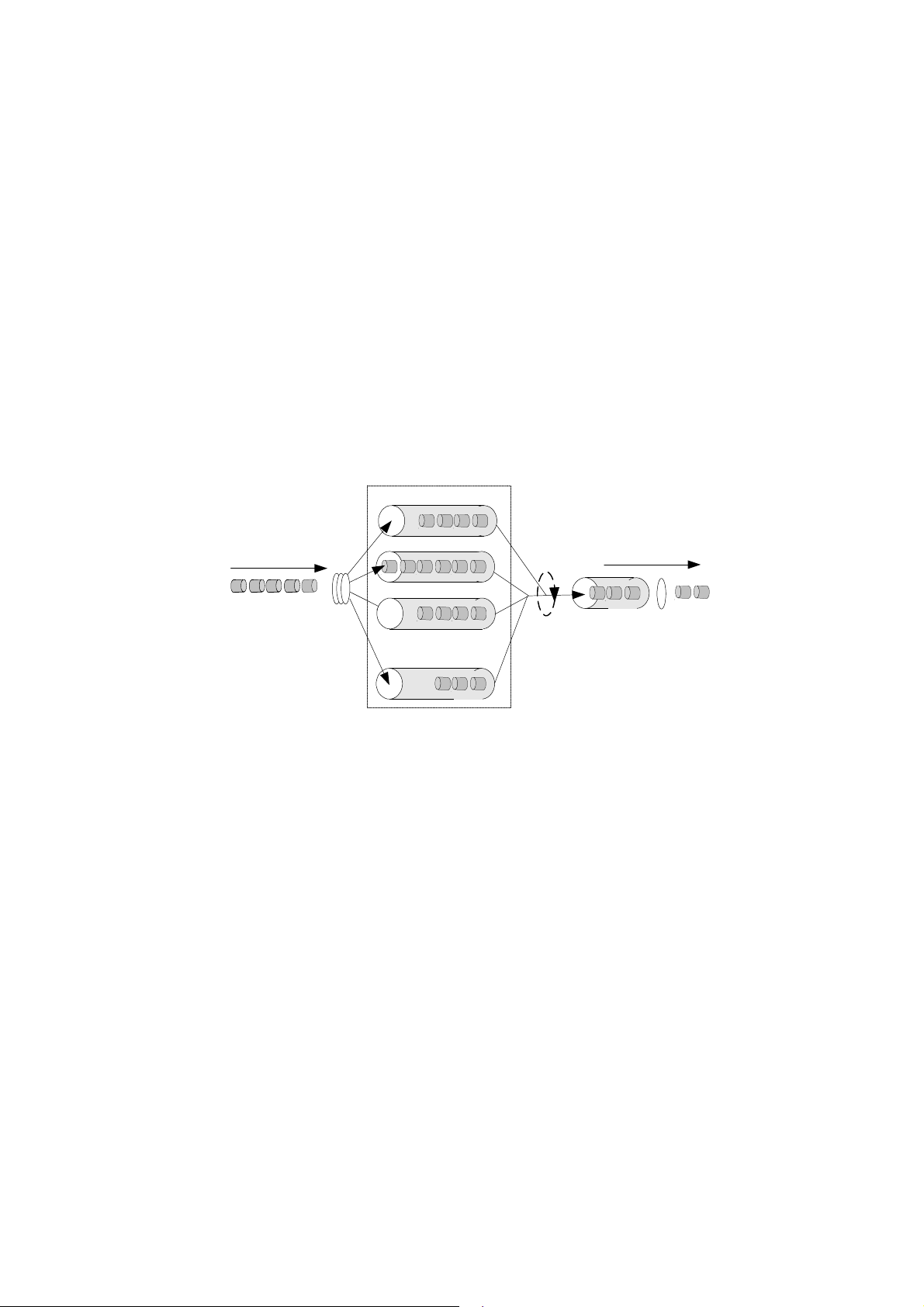
As an extension of WFQ, class based queuing (CBQ) provides users with class
definition support. CBQ assigns individual FIFO reservation queues to the classes
defined by each user to buffer data of the same class. When there is network
congestion, CBQ matches outbound packets according to the classification rule
defined by users to make them enter relevant queues. Before queue entry of packets,
the congestion avoidance mechanism (tail-drop or weighted random early detection
[WRED]) and bandwidth limit must first be checked. When packets leave the queues,
weighted fair scheduling of packets in the queues corresponding to each class should
be performed.
LLQ
IP Packets
Classifying
BQ1
BQ2
¡ ¡
BQ64
Outgoing first
Scheduling
Sent packets
Sent queue
Figure 1-1 CBQ diagram
If CBQ performs weighted fair treatment to queues of all classes, voice packets, the
delay-sensitive data flow may not be sent out in time. Therefore, PQ is introduced to
CBQ to create low latency queuing (LLQ), which provides strictly preferred sending
service for such delay-sensitive data flow as voice packets.
LLQ strictly combines PQ with CBQ. When a user defines a class, he can specify it to
accept strict priority service. The class of this type is called priority class. All packets
of the priority class enter the same priority queue. Before they enter a queue, the
bandwidth limit of each class of packets should be checked. When packets go out of
the queues, the packets in the priority queue are forwarded before packets in the
queues corresponding to other classes. But if the maximum reservation bandwidth
configured for LLQ is exceeded, the packets in other queue are sent. Weighted fair
scheduling will be performed to the packets in other queues when they are forwarded.
In order to avoid long time delay of packets in other queues, the maximum available
bandwidth can be specified for each priority class during LLQ application for traffic
Page 4

policing upon congestion. If no congestion occurs, the priority class is permitted to
3Com Router Configuration Guide Addendum for V1.20
4
use bandwidth exceeding the assigned value. In case of congestion, packets
exceeding the assigned bandwidth of the priority class will be discarded. Burst size is
also configurable under LLQ.
When the system matches packets with rules, it matches priority classes before other
classes. If there are multiple priority classes, they are matched one by one according
to configuration sequence. The same procedure is used to match packets and rules in
other classes. If there are multiple rules in a class, they are also matched one by one
according to the configuration sequence.
1.2 CBQ Configuration Tasks
CBQ (Class Based Queuing) configuration include s:
Define a class and enter the class view
Configure matching rules of a class
Define the policy and enter the policy view
Configure class in policy and enter policy-class view
Configure features of a class
Apply a policy to an interface
1.2.1 Define a Class and Enter the Class View
Defines a class and enters class view.
Perform the following configurations in the system view.
Table 1-1 Define a class and enter the class view
Operation Command
Define a Class and Enter the Class
View
Delete a class and enter class view
qos class [ logic-and | logic-or ] class-name
undo qos class [ logic-and | logic-or ] class-name
By default, a class named default-class is defined in the system. The class name
defined by the user “class-name” cannot be default-class.
By default, the defined class is logic-and and the interrelationship between matching
rules in the class view is logical AND.
1.2.2 Configure Matching Rules of a Class
1)
Define the rule for matching all packets
Perform the following configurations in class view.
Page 5

Table 1-2 Define/delete the rule matching all packets
3Com Router Configuration Guide Addendum for V1.20
5
Operation Command
Define the rule matching all packets
Delete the rule matching all packets
if-match [logic-not ] any
undo if-match [logic- not ] any
2)
Define the class matching rule
Perform the following configurations in class view.
Table 1-3 Define/delete the class matching rule
Operation Command
Define the class matching rule
Delete the class matching rule
if-match [ logic-not ] class class-name
undo if-match [ logic-not ] class class-name
Note:
This command cannot be used circularly. For example, qos class A defines the rules to match qos class
B, while qos class B cannot define a rule matching qos class A directly or indirectly.
3)
Define the ACL matching rule
Perform the following configurations in class view.
Table 1-4 Define/delete ACL matching rule
Operation Command
Define ACL matching rule
Delete ACL matching rule
if-match [ logic-not ] acl acl-number
undo if-match [ logic-not ] acl acl-number
4)
Define the MAC address matching rule
Perform the following configurations in class view.
Table 1-5 Define/delete the matching rule of a MAC address
Operation Command
Define MAC address matching rule
Delete MAC address matching rule
if-match [ logic-not ] { destination-mac | source-mac } mac-address
undo if-match [logic-not ] { destination-mac | source-mac }
mac-address
Note:
The matching rules of the destination MAC address are only meaningful for the policies in outbound
direction and the interface of Ethernet type.
Page 6

The matching rules of the source MAC address are only meaningful for the policies in inbound direction
3Com Router Configuration Guide Addendum for V1.20
6
and the interface of Ethernet type.
5)
Define the inbound interface matching rule of a class
Perform the following configurations in class view.
Table 1-6 Define/delete the inbound interface matching rule of a class
Operation Command
Define the inbound interface
matching rule of a class
Delete the inbound interface
matching rule of a class
if-match [ logic-not ] inbound-interface type number
undo if-match [ logic-not ] inbound-interface type number
}
6)
Define the DSCP matching rule
The differentiated services code point (DSCP) is a refined field from the 6 high bits of
ToS bytes in IP header by IETF DiffServ workgroup.In the solution submitted by
DiffServ, services are classified and traffic is controlled according to service
requirements at the network ingress. Simultaneously, DSCP is set. Communication
(including resource allocation, packet discard policy, etc.) is classified and served on
the basis of the grouped DSCP values
You can set classified matching rules according to DSCP values.
Perform the following configurations in class view.
Table 1-7 Define/delete DSCP matching rule
Operation Command
Define DSCP matching rule
Delete DSCP matching rule
if-match [ logic-not ] ip-dscp value [ value ] …
undo if-match [ logic-not ] ip-dscp value [ value ] …
7)
Define the IP precedence matching rule
Perform the following configurations in class view.
Table 1-8 Define/delete ip precedence matching rule
Operation Command
Define IP precedence matching rule if-match [ logic-not ] ip-precedence value [ value ] …
Delete IP precedence matching rule undo if-match [ logic-not ] ip-precedence …
Page 7

Use the corresponding command to configure the value of ip precedence during the
3Com Router Configuration Guide Addendum for V1.20
7
configuration; otherwise, the configuration of the if-match ip precedence command
will overwrite the previous configurations.
8)
Define the RTP port matching rule
Perform the following configurations in class view.
Table 1-9 Define/delete RTP port matching rule
Operation Command
Define RTP port matching rule
Delete RTP port matching rule
if-match [logic-not ] rtp start-port starting-port-number end-port
end-port-number
undo if-match [ logic-not ] rtp start-port starting-port-number
end-port end-port-number
Because the RTP priority queue (RTPQ) has a higher priority than that of CBQ, only
RTPQ will take effect if both RTPQ and the queue based on the class matching RTP
are configured at the same time.
9)
Define the protocol matching rule
Perform the following configurations in class view.
Table 1-10 Define/delete IP matching rule
Operation Command
Define IP matching rule
Delete IP matching rule
if-match [ logic-not ] protocol ip
undo if-match [ logic-not ] protocol ip
10)
Define the rule of all packets that do not satisfy the specified matching
rule.
Perform the following configurations in class view.
Table 1-11 Define/delete the rule of all packets not satisfying the specified matching rule
Operation Command
Define the rule of all packets not satisfying specified
matching rule
Delete the rule of all packets not satisfying specified
matching rule
if-match logic-not
undo if-match logic-not
criteria
criteria
Match-criteria: Matching rule of the class, including acl, any, class, destination-mac,
inbound-interface, ip-precedence, ip-dscp, protocol, rtp, source-mac.
1.2.3 Define the Policy and Enter the Policy View
Policy definition includes definition to the feature requirement for each class in the
policy, such as queue scheduling, including EF, AF, WFQ, TP, TS, and WRED.
Page 8

Perform the following configurations in the system view.
3Com Router Configuration Guide Addendum for V1.20
8
Table 1-12 Define the policy and enter the policy view
Operation Command
Define the policy and enter the policy
view
Delete the specified policy
qos policy policy-name
undo qos policy policy-name
If an interface applies this policy, this policy is not allowed to be deleted. You must
remove the application of this policy on the interface and then delete the policy with
the undo qos policy command.
1.2.4 Configure Class in Policy and Enter Policy-Class View
Perform the following configurations in the policy view.
Table 1-13 Configure class in policy and enter policy-class view
Operation Command
Configure class in policy
Remove the class configuration
qos-class class-name
undo qos-class class-name
class-name: Name of a class, of a defined class.
1.2.5 Configure Features of a Class in Policy
1)
Configure bandwidth
CBQ can set bandwidth and queuing length for each class.
Bandwidth is the minimum guarantee that the router can provide when congestion
occurs. If there is no congestion, each class can use the bandwidth larger than the
assigned one, but if there is congestion, for each class, all the packets exceeding the
assigned bandwidth will be dropped.
Queuing length is the maximum queue length of the class. When the queue is as long
as the preset length, new packets that want to enter the queue will be dropped.
Policy class configured with expedited-forwarding and bandwidth is a priority class
and will enter low latency queuing (LLQ).
Policy class configured with assured-forwarding and bandwid t h is an ordinary class.
The class that does not match any policy is called the default-class, and it can be
configured with assured-forwarding and bandwidth. After the default-class is
Page 9

configured with a maximum bandwidth, the system will assign the class an individual
3Com Router Configuration Guide Addendum for V1.20
9
queue, called the default queue.
Theoretically, each class can be configured with bandwidth of any size, but generally,
the priority classes can occupy 70% of the total bandwidth, and other ordinary classes
and the default class occupy less than 10%. It should be noted that the total
bandwidth assigned to each class and the RTP priority queue should not be larger
than the available bandwidth (the maximum bandwidth of the interface multiplied by
the percentage of the reserved bandwidth).
Please perform the following configurations in policy-class view.
Table 1-14 Configure assured-forwarding and the minimum bandwidth
Operation Command
Configure assured-forwarding for an
ordinary class or default class and
configure the minimum bandwidth for them
Delete the assured-forwarding undo af
Configure expedited-forwarding for priority
class and configure the maximum
bandwidth and CBS for it
Delete expedited-forwarding undo ef
af bandwidth { bandwidth | pct percentage }
ef bandwidth bandwidth [ cbs size ]
This function can only be applied on the outbound direction.
Note:
Priority classes must be configured with absolute bandwidth, while ordinary classes and the default class
can be configured with relative bandwidth (in percentage) or absolute bandwidth.
2)
Configure fair queue for the default class
Perform the following configurations in the policy-class view.
Table 1-15 Configure fair queue for the default class
Operation Command
Configure WFQ for the default class
Remove the configured WFQ of the default
class
wfq [ queue-number total-queue-number ]
undo wfq
Page 10

3)
3Com Router Configuration Guide Addendum for V1.20
10
Configure the maximum queue length of the class
Configure maximum queue length of the class and configure the drop type as tail
drop.
Perform the following configurations in the policy-class view.
Table 1-16 Configure the maximum queue length of the class
Operation Command
Configure the maximum queue length of the
class
Delete the configuration of maximum queue
length
queue-length queue-length
undo queue-length
This command can be used only after the af command has been configured. Execute
the undo af command then queue-length will be deleted as well.
For the default-class, this command can be used only after the af has been
configured.
4)
Configure the discarding mode of the class as random.
Perform the following configurations in the policy-class view.
Table 1-17 Configure the discarding mode of the class as random
Operation Command
Configure the discarding mode of the class
as random
Restore the default setting
wred [ ip-dscp value | ip-precedence value ]
undo wred [ ip-dscp value | ip-precedence value ]
ip-dscp indicates that the DSCP value is used to calculate the drop probability of a
packet.
Ip-precedence: Indicate that the IP precedence value is used to calculate drop
probability of a packet, which is the default setting.
This command cannot be used until the af command has been configured. In the
case of the default class, this command be used only after the af command has been
configured. The wred and queue-length commands are mutually exclusive. Other
configurations under the random drop will be deleted simultaneously when this
command is deleted. When a QoS policy including WRED is applied on an interface,
the original WRED configuration on the interface will be invalid.
The default-class can only be configured with the random discard mode based on IP
precedence.
5)
Configure exponential of average queue length calculated by WRED
Perform the following configurations in the policy-class view.
Page 11

Table 1-18 Configure exponential of average queue length calculated by WRED
3Com Router Configuration Guide Addendum for V1.20
11
Operation Command
Configure exponential of average queue
length calculated by WRED
Delete the configuration of exponential of
average queue length calculated by WRED
wred weighting-constant exponent
undo wred weighting-constant
This command can be used only after the af command has been configured and the
wred command has bee n used to enable WRED discard mode.
6)
Configure DSCP lower-limit, upper-limit and discard probability of
WRED
Perform the following configurations in the policy-class view.
Table 1-19 Configure DSCP lower-limit, upper-limit and discard probability of WRED
Operation Command
Configure DSCP lower-limit, upper-limit
and discard probability of WRED
Delete the configured DSCP lower-limit,
upper-limit and discard probability of
WRED
wred ip dscp value low-limit low-limit hjgh-limit high-limit
[ discard-probability discard-prob ]
undo wred ip-dscp value
value: DSCP value, in the range from 0 to 63, which can be any of the following
keywords: ef, af11, af12, af13, af21, af22, af23, af31, af32, af33, af41, af42, af43,
cs1, cs2, cs3, cs4, cs5 or cs7.
The discard mode based on WRED should have been enabled via the wred ip-dscp
command.
When the configuration of qos wred is deleted, the wred ip-dscp will also be
deleted.
When the af configuration is deleted, the configuration of discarding parameters will
also be deleted.
7)
Configure lower-limit, upper-limit and discarding probability of WRED
precedence
Perform the following configurations in the policy-class view.
Table 1-20 Configure lower-limit, upper-limit and discarding probability of WRED precedence
Operation Command
Configure lower-limit, upper-limit and
discard probability of WRED precedence
denominator
Delete the configuration of lower-limit,
upper-limit and discard probability of
WRED precedence denominator
wred ip-precedence value low-limit low-limit hjgh-limit high-limit
[ discard-probability discard-prob ]
undo wred ip-precedence value
Page 12

3Com Router Configuration Guide Addendum for V1.20
12
The discarding mode based on WRED must already have been enabled via the wred
ip-precedence command.
When the configuration of qos wred is deleted, the wred ip-precedence is also
deleted.
When the af configuration is deleted, the configuration of discarding parameters will
also be deleted.
8)
Enable/Disable traffic policing
Perform the following configurations in the policy-class view.
Table 1-21 Enable/Disable traffic policing for the class
Operation Command
Enable traffic policing for the class car cir rate [ cbs size ebs size ] [ conform action [ exceed action] ]
Disable traffic policing for the class undo car
In the table, action means actions taken on a data packet, including:
discard: Discard a packet.
pass: Send a packet.
remark-dscp-pass new-dscp: Set the value of new-dscp and send it. This value
ranges from 0 to 63.
remark-prec-pass new-prec: Set new IP priority new-prec and send it. This
value ranges from 0 to 7.
If TP is used in the class-policy applied on the interface, it can be applied on both
inbound and outbound interfaces.
When the class-policy including TP feature is applied on an interface, it invalidates the
original qos car command.
If this command is repeatedly configured on the same class policy, the last
configuration replaces the previous one.
The class configured with traffic policing without the application of AF or EF enters the
default queue if it passes traffic policing but encounters interface congestion.
9)
Configure traffic shaping (TS) for a class
Perform the following configurations in the policy-class view.
Table 1-22 Enable/disable TS for a class
Operation Command
Enable TS for a class gts cir rate [ cbs burst-size [ ebs size [ queue-length length ] ] ]
Disable TS for a class undo gts
Page 13

3Com Router Configuration Guide Addendum for V1.20
13
If qos gts is used in the class-policy that is applied to the interface, it can only be
applied to the outbound interface.
When the class including TS is applied to the interface, the original qos gts command
that is configured on the interface will become invalid.
If this command is repeatedly executed to configure the same class policy, the last
configuration replaces the previous one.
The class configured with TS without applying the configuration of AF or EF enters
the default queue if it passes traffic shaping but encounters interface congestion.
10)
Set DSCP value for the class to identify packets.
Perform the following configurations in the policy-class view.
Table 1-23 Set DSCP value for the class to identify packets
Operation Command
Set DSCP value for the class to identify packets remark ip-dscp value
Remove DSCP value that identifies packets
undo remark ip-dscp
11)
Set IP precedence value to identify matched packets
Perform the following configurations in the policy-class view.
Table 1-24 Set IP precedence value to identify matched packets
Operation Command
Set IP precedence value to identify matched
packets
Set IP precedence value to identify matched
packets
1.2.6 Apply a policy to an interface
The qos apply policy command applies a policy to a specific physical interface. A
policy can be used on multiple physical ports.
Perform the following configurations in class view.
Table 1-25 Associate an interface with the set policy
Operation Command
Apply an associated policy to an
interface
Delete an associated policy from an
interface
qos apply policy { inbound | outbound } policy-name
undo qos apply policy { inbound | outbound
remark ip-precedence value
undo remark ip-precedence
}
Page 14

3Com Router Configuration Guide Addendum for V1.20
14
The following is the rule for a policy to be applied in interface view .
A policy configured with various features (including remark, car, gts, af, ef, wfq,
and wred,) apply to a common physical interface and a virtual template interface
over MP.
The policy configured with TS (gts), and ef, af, wfq cannot be applied on the
interface as an inbound policy.
The sub-interface does not support ef, af, or wfq but supports TS (gts) and TP
(car). The policy configured with TS and TP can be applied on the sub-interface.
Note:
In the case of fast forwarding, CBQ is not supported.
1.2.7 Displaying and debugging CBQ
After the above configuration, execute display command in all views to display the
current class-based queue configuration, and to verify the effect of the configuration.
Table 1-26 Display and debug CBQ
Operation Command
Display class information configured on the
router
Display the configuration information of an
specified policy or a specified class in all
policies or all classes
Display the configuration information and
running status of an policy on a specified
interface
Display the configuration information and
running status of class-based queue on a
specified interface
Enable the debugging of a CBQ
display qos class [ class-name ]
display qos policy [ policy-name [ class class-name ] ]
display qos policy interface [ type number } [ inbound |
outbound ]
display qos cbq interface type umber
debugging qos cbq { af | be | ef | class } [ interface type
number ]
1.2.8 Typical CBQ Configuration Example
A typical CBQ configuration simultaneously transmits multiple service data on the
serial interface and satisfies the demand in various service flows by CBQ.
The networking diagram is shown below, wherein the bandwidth of serial0 is 64K,
PC1 sends service flow 1 to PC3, PC2 sends a service flow 2 to PC4, and there is
also a voice service flow.
Page 15
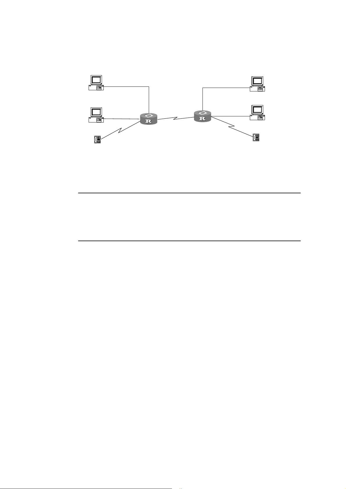
In terms of service, service flow 1 must occupy a bandwidth of 10K, service flow 2
3Com Router Configuration Guide Addendum for V1.20
15
must occupy a bandwidth of 20K, under the premise of ensuring voice service.
PC1
PC2
Tel ephone
1.1.1.1/24
10.1.1.1/24
E1
10.1.1.2/24
Router A
E0
1.1.1.2/24
s0 1.1.6.1
1.1.6.2/24
s0
E0 1.1.4.2/24
E1: 10.1.4.2/24
Router B
1.1.4.1/24
10.1.4.1/24
PC3
PC4
Tel epho ne
Figure 1-2 Networking diagram of CBQ configuration
Note:
This example only illustrates configurations corresponding to CBQ. The configurations of various
services and routes should be performed by the user independently. This example only configures CBQ
on Router A. Router B can be configured similarly.
Configure Router A:
1 Configure ACL rule.
[RouterA] acl 101
[RouterA-acl-101] rule normal permit ip source 1.1.0.0 0.0.255.255 destination
any
[RouterA] acl 102
[RouterA-acl-102] rule normal permit ip source 10.1.0.0 0.0.255.255 destination
any
2 Configure class 1:
[RouterA] qos class logic-and 1
[RouterA-qosclass-1] if-match acl 101
[RouterA-qosclass-1] quit
3 Configure class 2:
[RouterA] qos class logic-and 2
[RouterA-qosclass-2] if-match acl 102
[RouterA-qosclass-2] quit
4 Configure priority class:
[RouterA] qos class logic-and voip
Page 16

[RouterA-qosclass-voip] if-match rtp start-port 16384 end-port 32767
3Com Router Configuration Guide Addendum for V1.20
16
[RouterA-qosclass-voip] quit
5 Configure CBQ policy:
[RouterA] qos policy 1
6 Configure the bandwidth of service 1 to be 10K:
[RouterA-qospolicy-1]qos-class 1
[RouterA-qospolicy-c-1 1] af bandwidth 10
[RouterA-qospolicy-c-1 1] quit
7 Configure the bandwidth of service 2 to be 20K:
[RouterA-qospolicy-1]qos-class 2
[RouterA-qospolicy-c-1 2] af bandwidth 20
[RouterA-qospolicy-c-1 2] quit
8 Configure the voice service to be priority service:
[RouterA-qospolicy-1]qos-class voip
[RouterA-qospolicy-c-1 voip] ef bandwidth 10 cbs 1500
[RouterA-qospolicy-c-1 voip] quit
9 Apply CBQ policy 1 to Serial0:
[RouterA] interface serial 0
[RouterA-Serial0] qos apply policy outbound 1
10 Remove fast-forwarding on the interface. (The interface does not support CBQ
in the case of fast-forwarding.)
[RouterA-Serial0] undo ip fast-forwarding
Page 17
Chapter 2 Configuring TACACS+
3Com Router Configuration Guide Addendum for V1.20
17
TACACS+ is facilitated with AAA to control PPP, VPDN, and login access to routers.
CISCO ACS is the only application software that is supported.
Compared to RADIUS, TACACS+ features more reliable transmission and encryption,
and is more suitable for security control. The following table lists the primary
differences between TACACS+ and RADIUS protocols.
Table 2-1 Comparison between the TACACS+ protocol and the RADIUS protocol
TACACS+ protocol RADIUS protocol
Adopts TCP and hence can provide more reliable network
transmission.
Encrypts the entire main body of the packets except for
the standard TACACS+ header.
Supports separate authentication and authorization. For
example, you can use RADIUS for authentication but
TACACS+ for authorization.
If RADIUS is used for authentication before authorizing
with TACACS+, RADIUS is responsible for confirming
whether a user can be accepted, and TACACS+ is
responsible for the authorization.
Is well suited to security control. Is well suited to accounting.
Supports authorization before the configuration commands
on the Router can be used.
Adopts UDP.
Encrypts only the password field in the
authentication packets.
Processes authentication and authorization
together.
Does not support authorization before
configuration.
In a typical TACACS+ application, a dial-up or terminal user needs to log in the router
for operations. Working as the TACACS+ client in this case, the router sends the user
name and password to the TACACS+ server for authentication. After passing the
authentication and getting the authorization, the user can log in to the router to
perform operations, as shown in the following figure.
Terminal
Terminal user
Terminal
Terminal
Terminal user
H W TA CACS se rver
H W TA CACS se rver
H W TA CACS se rver
H W TA CACS se rver
H W TA CACS se rver
129.7.66.66
129.7.66.66
129.7.66.66
129.7.66.66
129.7.66.66
ISDN\PSTN
ISDN\PSTN
ISDN\PSTN
ISDN\PSTN
ISDN\PSTN
Router
Router
Router
Router
Router
Dial-up
Dial-up us er
Dial-up
Dial-up
Dial-up us er
HWTACACS client
HWTACACS client
HWTACACS client
HWTACACS client
HWTACACS client
H W TA CACS se rver
H W TA CACS se rver
H W TA CACS se rver
H W TA CACS se rver
H W TA CACS se rver
129.7.66.67
129.7.66.67
129.7.66.67
129.7.66.67
129.7.66.67
Figure 2-2 Networking for a typical TACACS+ application
Page 18

2.2 The Basic Message Interaction Flow of TACACS+
3Com Router Configuration Guide Addendum for V1.20
18
For example, use TACACS+ to implement AAA on a telnet user, and the basic
message interaction flow described below is used:
1) A user requests access to the router. The router(TACACS+ client) sends the
authentication start packet to the TACACS+ server upon receipt of the request.
2) The TACACS+ server sends an authentication response packet requesting the
user name. The router (TACACS+ client) asks the user for the user name upon
receipt of the response packet.
3) After receiving the user name from the user, the router (TACACS+ client) sends
the authentication packet to the TACACS+ carrying the user name.
4) The TACACS+ server sends back an authentication response packet, requesting
the login password. Upon receipt of the response packet, the router (TACACS+
client) requests the user for the login password.
5) The router (TACACS+ client) sends an authentication packet carrying the login
password to the TACACS+ server.
6) The TACACS+ server sends back the authentication response packet indicating
that the user has passed the authentication.
7) The router (TACACS+ client) sends the user authorization packet to the
TACACS+ server.
8) The TACACS+ server sends back the authorization response packet, indicating
that the user has passed the authorization.
9) Upon receipt of the response packet indicating an authorization success, the
router (TACACS+ client) pushes the configuration interface of the router to the
user.
10) The router (TACACS+ client) sends the accounting start request packet to the
TACACS+ server
11) The TACACS+ server sends back an accounting response packet, indicating that
it has received the accounting start request packet.
12) The user quits, and the router (TACACS+ client) sends the accounting stop
packet to the TACACS+ server.
13) The TACACS+ server sends back the accounting stop packet, indicating that the
accounting stop request packet has been received.
The following figure illustrates the basic message interaction flow:
Page 19

User
3Com Router Configuration Guide Addendum for V1.20
19
User
Us er l ogs in
Us er l ogs in
Re quest Us er for the u s er name
Re quest Us er for the u s er name
Us er enters the us er name
Us er enters the us er name
Re quest Us er for the password
Re quest Us er for the password
Us er enters the pas sword
Us er enters the pas sword
Us er is per m itted
Us er is per m itted
HWTACACS
HWTACACS
Client
Client
Authenti cation Start Request p a cket
Authenti cation Sta rt Request p a cket
A uthenti cation response packet,
A uthenti cation response packet,
requesting for the us er nam e
requesting for the us er nam e
A uthentication continu ance pac ket
A uthentication continu ance pac ket
carr ying the user name
carr ying the user name
A uthenti cation response packet,
A uthenti cation response packet,
requesting for the pas swor d
requesting for the pas swor d
A uthentication continu ance pac ket
A uthentication continu ance pac ket
carr y ing th e pass w or d
carr y ing th e pass w or d
A u then tication succes s packet
A u then tication succes s packet
A uthorization request pack et
A uthorization request pack et
A uthori zation success pack et
A uthori zation success pack et
A cco unting start req uest packet
A cco unting start req uest packet
Accounting start response packet
Accounting start response packet
HWTACACS
HWTACACS
Serv er
Serv er
Us er qui ts
Us er qui ts
Accounting stop p acke t
Accounting stop p acke t
A cc ounti ng sto p response packet
A cc ounti ng sto p response packet
Figure 2-3 The flow of implementing AAA for a telnet user
2.3 The TACACS+ Functions Implemented by 3Com Routers
3Com Routers support the following T ACACS+ functions:
1) AAA on login users (including console, Telnet, dumb terminal, PAD, terminal
accessing, and FTP users)
2) AAA on PPP users
3) AAA on VPDN users (L2TP is used in this case)
2.4 TACACS+ Configuration Tasks
Basic TACACS+ configuration tasks include:
Create a TACACS+ server group
Add the TACACS+ server into a TACACS+ server group
High-level T A CACS+ configuration t asks include:
Page 20

3Com Router Configuration Guide Addendum for V1.20
20
Standby/Primary server switchover interval
The shared key for the AAA negotiation between the router and TACACS+
Server
Set the timeout time waiting for a TACACS+ server to make a response
Specify a source IP address for all the TACACS+ packets to be transmitted
2.4.1 Create a TACACS+ server group
Before a TACACS+ server can be used to implement AAA, you should first create a
TACACS+ server group and put the TACACS+ server into the group. The router will
look up the group for a TACACS+ server to implement AAA. You can create a
maximum of 11 TACACS+ server groups.
Perform the following configuration in system view.
Table 2-2 Create a TACACS+ server group
Operation Command
Create a TACACS+ server group
by specifying its name
Delete a TACACS+ server group
by specifying its name
hwtacacs-server template template-name
undo hwtacacs server template template-name
By default, no server group is configured.
2.4.2 Add a TACACS+ Server into a TACACS+ Server Group
After a TACACS+ server group is created, you add TACACS+ servers into it. Each
group allows of a maximum of 5 servers.
Perform the following configuration in TACACS+ view.
Table 2-3 Add/Delete TACACS+ servers
Operation Command
Add a TACACS+ server into a
TACACS+ server group
Remove a TACACS+ server from
a TACACS+ server group
host ip ip-address
[
shared-key key-string
account-primary
undo host ip ip-address
account-primary
By default, no TACACS+ Server is specified.
[
port port-number
] [
]
]
] [
authen-primary | author-primary |
[
authen-primary | author-primary |
response-timeout time
]
Page 21

Note:
3Com Router Configuration Guide Addendum for V1.20
21
When this command is used without being configured with the parameter shared-key key-string for
negotiation, the default key configured using the shared-key command will be used.
2.4.3 Standby/Primary Server Switchover Interval
If you have specified the primary and standby servers in a TACACS+ server group,
the router regularly tests whether the primary server can work properly in the case
that the current server used to provide AAA services is a standby server. Once it finds
that the specified primary server can work normally, it switches from the current
standby server to the primary server. You can configure the interval for switching.
Perform the following configuration in TACACS+ view.
Table 2-4 Configure a standby/primary server switchover interval
Operation Command
Configure a standby/primary server switchover interval
Restore the default standby/primary server switchover
interval
timer quiet minute
undo timer quiet
s
The standby/primary server switchover interval defaults to five minutes.
2.4.4 Set a Shared Key for the AAA Negotiation Between Router and
TACACS+ Server
Setting a shared key can ensure the security of the communications between router
and TACACS+ server. By default, the system does not set a key. Therefore, you
should use this command to set a shared key in the case that a TACACS+ server is
used as the AA A server.
Perform the following configuration in system view.
Table 2-5 Set a shared key for the AAA negotiation between router and TACACS+ server
Operation Command
Configure a shared key for the AAA negotiati on with any
TACACS+ servers in a specified TACACS+ server group
Delete the shared key for the AAA negotiation with the
TACACS+ servers in a specified TACACS+ server group
shared-key key-string
undo shared-key
By default, no key is set.
Page 22

Caution:
3Com Router Configuration Guide Addendum for V1.20
22
1) The entered key must match the key used by the TACACS+ server.
2) All the leading spaces and ending spaces in a key string will be ignored. In addition, a key that
contains spaces in the middle is not supported.
2.4.5 Specify a Source IP Address for the TACACS+ Packets to be
Transmitted
You can specify a source IP address for the TACACS+ packets sent from different
interfaces on the router. In this way, the TACACS+ server will contact the router only
at that IP address.
A TACACS+ server requires the administrator to register all the TACACS+ clients. The
clients are scrutinized on the basis of their source IP address. Therefore, the different
interfaces on the same router are regarded by the TACACS+ server as different
clients. Whenever the TACACS+ server receives a packet carrying an unregistered
source IP address, it regards the packet as illegal and hence does no processing on
it.
Caution:
You must make sure that the specified source IP address is the IP address of some interface on the
router, and that the server maintains the route to that IP address. You can configure a loopback interface
on the router, specify an IP address for it, and use this address as the source IP address of the
TACACS+ packets.
Perform the following configuration in system view.
Table 2-6 Specify the source IP address for the transmitted TACACS+ packets
Operation Command
Configure the source IP address for the
transmitted TACACS+ packets
Remove the source IP address specified for
the TACACS+ packets to be transmitted
source-ip
interface-number
undo source-ip
{
ip-address
}
|
interface interface-type
By default, the source IP address is the IP address of the interface where the
TACACS+ packets are sent.
Page 23

2.5 Displaying and Debugging TACACS+
3Com Router Configuration Guide Addendum for V1.20
23
Execute the following commands in all views.
Table 2-7 Display and debug AAA and RADIUS
Operation Command
Display all the accounting details.
Display all the router-TACACS+
interaction details.
Clear all the accounting details.
Clear all the router-TACACS+
interaction details.
Enable the debugging of AAA
implemented using TACACS+
Disable the debugging of AAA
implemented using TACACS+
display hwtacacs accounting [ verbose
display hwtacacs server
[
reset hwtacacs accounting statistics
reset hwtacacs server statistics
debugging hwtacacs { authentication | authorization |
accounting
interface-name ]
} [
packet
] [
user user-name
undo debugging hwtacacs { authentication | authorization |
accounting
} [
packet
interface-name ]
2.6 Implementing AAA Using TACACS+
verbose
] [
]
]
][
interface
user user-name
][
interface
Use TACACS+ to implement AAA on PPP and login users.
Terminal user
Terminal user
192.10.1.0/24
192.10.1.0/24
TACAC S + server
TACAC S + server
10.110.1.1
10.110.1.1
TACAC S + server
TACAC S + server
10.110.1.2
10.110.1.2
Dial-up us er
Dial-up us er
ISDN\PSTN
ISDN\PSTN
168.1.1.1
168.1.1.1
E1:192.10.1.1
E1:192.10.1.1
S0:
S0:
Router
Router
Accessed network
Accessed network
E0:
E0:
10.110.1.10
10.110.1.10
Figure 2-4 Networking for the AAA implementation using TACACS+
To configure T A CACS+:
1 Create a TACACS+ server group and add TACACS+ servers into it.
[3Com] HWTACACS-server template tactemplate1
[3Com-HWTACACS-tactemplate1]host ip 10.110.1.1 authen-primary
[3Com-HWTACACS-tactemplate1]host ip 10.110.1.1 author-primary
[3Com-HWTACACS-tactemplate1]host ip 10.110.1.1 account-primary
[3Com-HWTACACS-tactemplate1]host ip 10.110.1.2
Page 24

2 Configure “mykey” as the shared key for the AAA negotiation with the
3Com Router Configuration Guide Addendum for V1.20
24
TACACS+ server.
[3Com-HWTACACS-tactemplate1]shared-key mykey
[3Com-HWTACACS-tactemplate1] quit
3 Enable AAA.
[3Com]aaa-enable
4 Implement authentication on telnet login users.
[3Com]login telnet
[3Com]aaa authentication-scheme login login-authen-list template tactemplate1
[3Com] login-method authentication-mode telnet login-authen-list
5 Implement authentication on the PPP users accessed from the interface
Serial0.
[3Com]aaa authentication-scheme ppp ppp-authen-list template tactemplate1
[3Com]interface serial 0
[3Com-Serial0] link-protocol ppp
[3Com-Serial0] ppp authentication-mode pap scheme ppp-authen-list
[3Com-serial0] quit
6 Configure a login authorization scheme.
[3Com]aaa authorization-scheme login login-author-list template tactemplate1
7 Specify an authorization scheme for login users.
[3Com]login-method authorization-mode telnet login-author-list
8 Enable PPP authorization and use the ppp-author-list authorization scheme on
Serial0.
[3Com]aaa authorization-scheme ppp ppp-author-list template tactemplate1
[3Com]interface serial 0
[3Com-Serial0]link-protocol ppp
[3Com-Serial0]ip address 168.1.1.1 255.255.255.0
[3Com-Serial0]ppp authorization-mode ppp-author-list
[3Com-serial0] quit
9 Enable login accounting and configure the accounting scheme account-list.
[3Com] aaa accounting-scheme login login-account-list template tactemplate1
10 Use the login-account-list scheme to enable accounting for telnet login users.
[3Com]login-method accounting-mode login telnet login-account-list
11 Enable accounting and use the ppp-account-list accounting scheme on Serial0.
[3Com] aaa accounting-scheme ppp ppp-account-list template tactemplate1
[3Com] interface serial 0
[3Com-Serial0] link-protocol ppp
[3Com-Serial0] ppp accounting ppp-account-list
Page 25

[3Com-serial0] quit
3Com Router Configuration Guide Addendum for V1.20
25
12 Assign an IP address to the interface Ethernet0.
[3Com]interface ethernet 0
[3Com-ethernet0]ip address 10.110.1.10 255.255.0.0
13 Assign an IP address to Ethernet1.
[3Com-ethernet0]interface ethernet 1
[3Com-ethernet0]ip address 192.10.1.1 255.255.255.0
[3Com-ethernet0]return
2.6.2 Integrating TACACS+ and RADIUS
In this example, a TACACS+ server is used for authentication and authorization for
PPP and login users, and is also used as a standby accounting server. A RADIUS
server is used for accounting, and is also used as the standby server for
authentication and authorization.
Terminal user
Terminal user
192.10.1.0/24
192.10.1.0/24
TACAC S + server
TACAC S + server
10.110.1.1
10.110.1.1
RADIUS se rver
RADIUS se rver
10.110.1.2
10.110.1.2
Dial-up us er
Dial-up us er
ISDN\PSTN
ISDN\PSTN
168.1.1.1
168.1.1.1
E1:192.10.1.1
E1:192.10.1.1
S0:
S0:
Router
Router
Accessed network
Accessed network
E0:
E0:
10.110.1.10
10.110.1.10
Figure 2-5 Networking for the application combining TACACS+ and RADIUS
To integrate TACACS+ and RADIUS:
1 Enable AAA.
[3Com]aaa-enable
2 Configure TACACS+.
3 Create a TACACS+ server group and add TA CACS+ servers into it.
[3Com] HWTACACS-server template tactemplate1
[3Com-HWTACACS-tactemplate1]host ip 10.110.1.1 authen-primary
[3Com-HWTACACS-tactemplate1]host ip 10.110.1.1 author-primary
4 Configure “mykey” as the shared key for the AAA negotiation with the
TACACS+ server.
Page 26

[3Com-HWTACACS-tactemplate1] shared-key mykey
3Com Router Configuration Guide Addendum for V1.20
26
[3Com-HWTACACS-tactemplate1] quit
5 Configure the IP address, authentication port, and accounting port on the
RADIUS server.
[3Com]radius server 10.110.1.2
6 Configure the key, retransmission times, and the timeout time for the RADIUS
server.
[3Com] radius shared-key my-secret
[3Com] radius retry 2
[3Com] radius timer response-timeout 5
7 Configure authentication of Telnet login users.
[3Com]login telnet
[3Com]aaa authentication-scheme login telnet-authen-list template
tactemplate1 radius
[3Com]login-method authentication-mode telnet telnet-authen-list
8 Configure authentication of PPP users on the interface Serial0.
[3Com]aaa authentication-scheme ppp ppp-authen-list template tactemplate1
radius
[3Com]interface serial 0
[3Com-Serial0] link-protocol ppp
[3Com-Serial0] ppp authentication pap scheme ppp-authen-list
[3Com-serial0] quit
9 Enable login authorization and configure an authorization scheme.
[3Com]aaa authorization-scheme login login-author-list template tactemplate1
10 Apply a telnet login authorization scheme.
[3Com]login-method authorization-mode telnet login-author-list
11 Enable PPP authorization and use the authorization scheme named “test-list”
on Serial0.
[3Com]aaa authorization-scheme ppp ppp-author-list template tactemplate1
[3Com]interface serial 0
[3Com-Serial0]link-protocol ppp
[3Com-Serial0]ip address 168.1.1.1 255.255.255.0
[3Com-Serial0]ppp authorization-mode ppp-author-list
[3Com-serial0] quit
12 Enable accounting for login users and configure the default accounting
scheme.
[3Com] aaa accounting-scheme login default radius template tactemplate1
[3Com] aaa accounting-scheme optional
Page 27

13 Apply the default scheme for accounting on telnet login users.
3Com Router Configuration Guide Addendum for V1.20
27
[3Com]login-method accounting-mode login telnet default
14 Enable accounting on Serial0, and configure and apply the default accounting
scheme.
[3Com] aaa accounting-scheme ppp default radius template tactemplate1
[3Com]interface Serial0
[3Com-Serial0]link-protocol ppp
[3Com-Serial0]ppp accounting default
[3Com-serial0] quit
15 Assign an IP address to Ethernet0.
[3Com]interface ethernet 0
[3Com-ethernet0]ip address 10.110.1.10 255.255.0.0
16 Assign an IP address to Ethernet1.
[3Com-ethernet0]interface ethernet 1
[3Com-ethernet0]ip address 192.10.1.1 255.255.255.0
[3Com-ethernet0]return
2.7 Troubleshooting
A user always fails to pass the authentication implemented through TACACS+.
Do the following:
Check whether the correct user name and password and the available services
for the user have been configured on the TACACS+ server.
Check whether the TACACS+ server can be pinged, and whether the correct
address and port number and shared-key of the server have been configured on
the router.
Use the host command to reconfigure the TACACS+ server. Due to the failure in
communicating with the RADIUS server, the system regards the RADIUS server
as unavailable. In this case, you can use the undo host command to remove the
RADIUS server that has been configured, and then use the host command to
reconfigure the RADIUS server. Thus, the RADIUS server will be able to work
without any delay.
Check proper configurations have been made for the TACACS+ server and
whether the modifications just made have taken effect.
Page 28

Chapter 3 Configuring SSH Terminal Service
3Com Router Configuration Guide Addendum for V1.20
28
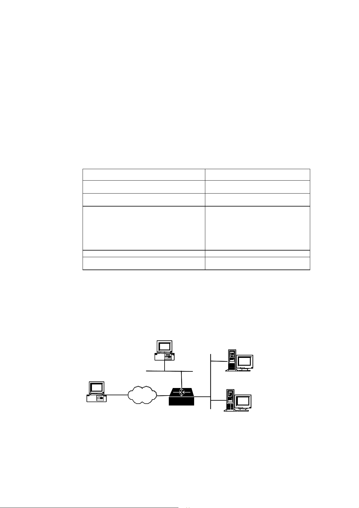
Secure Shell (SSH) is a feature that provides information about security and powerful
authentication functions, which can protect a router from the attacks such as IP
address spoofing and plain text password. This is especially evident for remote users
who access the router from a nonsecure network environment. The router provides
simultaneous access of multiple SSH clients. SSH client allows a user to set up the
SSH connection with an SSH-supported router or UNIX host. As shown in Figures 2-1
and 2-2, you can set up an SSH channel for the purpose of local or WAN connection.
V1.20 supports SSH Server 1.5.
Router
Router
Workstation
Workstation
Ethernet
Ethernet
100BASE-TX
100BASE-TX
Laptop
Laptop
Server
Server
SSH Client-enabled PC
SSH Client-enabled PC
Set up an SSH channel in a LAN
Workstation
Workstation
Server
Server
Local LAN
Local LAN
Ethernet
Ethernet
Laptop
Laptop
Local SSH-enabled
Local SSH-enabled
PC
PC
Router
Router
Local router
Local router
WAN line
WAN line
WAN
WAN
Router to be configure d
Router to be configure d
Router
Router
Remote LAN
Remote LAN
Ethernet
Ethernet
PC
PC
Laptop
Laptop
Workstation
Workstation
Server
Server
Set up an SSH channel across WAN
Page 29

To set up a secure and authenticated SSH connection, the server and client must go
3Com Router Configuration Guide Addendum for V1.20
29
through the communication procedure that falls into five stages; version negotiation,
key algorithm negotiation, authentication type negotiation, session request, and
session interaction.
3.1 Configuring SSH
The basic configuration of SSH is required for the SSH Client to connect to the SSH
Server (router) successfully. Advanced SSH configurations are optional.
Basic SSH configurations include:
Set the protocol supported by the system and the allowed maximum number of
connections
Configure and destroy the local RSA key-pair
Configure authentication type for an SSH user
Advanced SSH configurations include:
Set the interval for updating server key
Set timeout time in SSH authentication
Set the number of SSH authentication retries
Access the public key view and edit the key
Assign a public key to an SSH user
The default remote login protocol is Telnet, instead of SSH. You must set the remote
login protocol supported by the system to SSH and set the maximum number of the
connections.
Perform the following configuration in system view.
Table 3-1 Set remote login protocol and the maximum number of connections
Operation Command
Set the remote login protocol supported by
the system and the allowed maximum
number of connections
protocol inbound { ssh
|
telnet
}
numbers [ acl acl-number
]
By default, only Telnet is supported (in this case, up to five simultaneous connections
are allowed), SSH login is not supported, and ACL is not used.
Perform this task to generate server and host key-pairs. If there exist RSA key-pairs,
the system will ask if you want to replace the existing keys. The generated key-pairs
are represented by “router name + server” and “router name + host”. A server key-pair
and a host key-pair have a difference of at least 128 bits in size. Both of them have
the same minimum and maximum sizes, i.e., 512 bits and 2048 bits .
Perform the following configuration in system view.
Page 30

Table 3-2 Configure and destroy RSA key-pairs
3Com Router Configuration Guide Addendum for V1.20
30
Operation Command
Generate RSA key-pairs
Destroy the RSA key-pairs
rsa local-key-pair create
rsa local-key-pair destroy
Caution:
An essential operation underlying a successful SSH login is generating local RSA key-pairs. Before
performing any other SSH configuration tasks, you must generate a local key-pair by configuring the rsa
local-key-pair create command.
It is only necessary for you to execute this command once and you do not have to execute it again after
rebooting the router.
II. Configure Authentication Type for an SSH User
Only SSH users can pass the SSH authentication. There are two SSH authentication
modes: password authentication and RSA authentication. You can use both at the
same time.
When configuring the SSH user, you must set the SSH user ’s rights (Administrator,
Operator or Guest) and specify the authentication mode.
Perform the following configuration in system view.
Table 3-3 Configure authentication type for an SSH user
Operation Command
Configure an SSH user
Configure an authentication type for
an SSH user
Remove the authentication type set
for the specified SSH user
local-user username service-type ssh
guest
}
password
ssh user username authentication-type
undo ssh user username authentication-type
{
simple
|
cipher
{
administrator
}
password
{
password
|
|
RSA
operator
|
all
|
}
By default, login authentication type is not specified for users. Login requests are
refused.
Perform this task to set a server key-pair updating interval for securing the SSH
connections to the system.
Perform the following configuration in system view.
Table 3-4 Set server key-pair updating interval
Operation Command
Page 31

Set a server key-pair updating
3Com Router Configuration Guide Addendum for V1.20
31
interval
Restore the default updating interval
ssh server rekey-interval hours
undo ssh server rekey-interval
By default, the system does not update the server key-pair.
Perform this task to set an SSH authentication timeout time period.
Perform the following configuration in system view.
Table 3-5 Set SSH authentication timeout time
Operation Command
Set SSH authentication timeout time
Restore the default SSH authentication
timeout time setting
ssh server timeout seconds
undo ssh server timeout
The SSH authentication timeout time of the system defaults to 60 seconds.
Perform this task to set the authentication retry attempts for an SSH connection
request to prevent unauthorized access.
Perform the following configuration in system view.
Table 3-6 Set the number of SSH authentication retries
Operation Command
Set the number of SSH authentication retries
Restore the default number of SSH
authentication retries
ssh server authentication-retries times
undo ssh server authentication-retries
By default, the parameter times defaults to 3.
III. Access the Public Key View and Edit the Key
To configure public key, you must enter the public key view first.
Perform the following configuration in system view.
Table 3-7 Configure a public key
Operation Command
Access the public key view.
Remove the specified public key.
rsa peer-public-key key-name
undo rsa peer-public-key key-name
After accessing the public-key edit view by executing the rsa peer-public-key
command, you can input the key data by using the public-key-code begin command.
You can input the key data using the hex command. You are allowed to input spaces
Page 32

when entering key data but they will be deleted by the system. The configured public
3Com Router Configuration Guide Addendum for V1.20
32
key must be a consecutive hexadecimal character string coded in the public key
format. Execute the public-key-code end command to stop public key editing and
save the key. Before you save the key however, you should verify the validity of the
key in case the key data are rendered useless due to illegal characters contained in
the public key string.
Perform the following configuration in public-key view.
Table 3-8 Start/Stop public key editing
Operation Command
Access the public key edit view
Stop public key editing and exit
the public key edit view
public-key-code begin
public-key-code end
Public key is generated by the Client software supporting SSH1.5 lowe r.
Perform the following configuration in public key edit view.
Table 3-9 Edit a public key
Operation Command
Input the public key data
hex hex-data
IV. Assign a Public Key to an SSH User
Perform this task to assign a public key that has been configured to an SSH user.
Perform the following configuration in system view.
Table 3-10 Assign a public key to an SSH user
Operation Command
Assign a public key to an SSH user
Remove the association between the
user and the public key
ssh user username assign rsa-key keyname
undo ssh user username assign rsa-key
V. Close an SSH Process by Force
A system administrator can disconnect the connections of all the SSH login users by
force by executing the kill command on the console interface, or close by force the
SSH process of a specified SSH login user found by executing the display
local-user online command.
Page 33

Perform the following configuration in system view.
3Com Router Configuration Guide Addendum for V1.20
33
Table 3-11 Close SSH processes by force
Operation Command
Kill SSH process(es) by force
kill ssh
all
|
userID userid
{
}
VI. Display and Debug SSH Information
After finishing the configurations described above, view the running state of SSH by
executing the display commands in all views to verify the configuration.
You can debug the SSH information by executing the debugging commands in all
views.
To make better use of the system resources and make the communications more
secure, you can view the configurations of all the SSH users by displaying and
debugging the SSH information.
Perform the following operation in all views.
Table 3-12 View the SSH involved information
Operation Command
View the public key portions of the host and
the server key-pairs
Display the client-end RSA public keys
Display the SSH status and session
information
Display the SSH user information
Enable SSH debugging
Enable RSA debugging
Disable SSH debugging
Disable RSA debugging
3.1.2 Configure SSH Client
SSH client software includes applications such as PuTTy, FreeBSD, and other client
software that is available on the market. To set up a connection with the server, you
need to perform the basic configurations on the SSH client, including:
display rsa local-key-pair public
display rsa peer-public-key [ brief | name keyname
display ssh server { status
display ssh user-information [ username
debugging ssh server
debugging rsa
undo debugging ssh server
undo debugging rsa
{
|
session
VTY index | all
VTY index | all
{
]
}
]
}
}
Specify the IP address of the server.
Set the remote connection protocol to SSH. Generally, the client supports
multiple remote connection protocols, such as Telnet, Rlogin and SSH. To set up
an SSH connection, you must set the protocol to SSH.
Page 34

3Com Router Configuration Guide Addendum for V1.20
34
Choose the proper SSH version. Generally the client provides several SSH
versions. V1.20 supports SSH Server 1.5, so you must choose 1.5 or lower.
Specify the RSA key file. If you have configured to choose RSA authentication at
the server, you must specify the RSA key file at the client. In normal case, RSA
key file is created by the tool attached to the client software, including a pair of
public key used for the server (router) and private key used for the client.
Use the third party client software, PuTTY in the following example, to set the
configuration of SSH client.
I. Specify the IP address of the server
Enable the PuTTY program and the following client configuration interface appe ars.
Figure 3-1 SSH Client configuration interface (1)
Enter the IP address of the router in the field “Host Name (or IP address)”. The
address can be the IP address of the interface whose protocol status is “up” on any
router, but the route to the SSH client can be reachable, for exam ple , 10.110.28.10.
II. Set the remote connection protocol to SSH
Choose "SSH” as the protocol in the above interface.
Page 35

III. Choose the SSH version
3Com Router Configuration Guide Addendum for V1.20
35
Click “SSH” under “Connection” in the left “Category” of the interface, then the
following interface appears.
Figure 3-2 SSH Client configuration interface (2)
Specify the SSH version to “1”, as shown in the above interface.
IV. Enable the SSH connection in password authentication mode
Click [Open] button and the SSH Client interface appears. If the connection is normal,
then you are prompted to enter user name and password, as shown in the following
figure.
Page 36

3Com Router Configuration Guide Addendum for V1.20
36
Figure 3-3 SSH Client login interface (in password authentication mode )
After you have entered the correct user name and password, you can implement the
connection.
To log out, just use the logout command.
V. Enable the SSH connection in RAS authentication mode
To enable the SSH connection in RSA mode, you need to configure the RSA key on
both the SSH server and client.
Take the following method to generate keys using PuTTY key generator
software.
Enable the PuTTY key generator software, as shown in the following.
Page 37

3Com Router Configuration Guide Addendum for V1.20
37
Figure 3-4 PuTTY Generator Software interface (1)
Choose “SSH1(RSA)” or “SSH2 RSA” as the parameter and enter the number of bits
in the key.
Click [Generate] button to generate the RSA key. To ensure the random key, you are
required to move the mouse. Once you stop moving the cursor, the generating
process will pause.
After the key is generated, the following interface appears.
Page 38

3Com Router Configuration Guide Addendum for V1.20
38
Figure 3-5 PuTTY Key Generator interface (2)
Enter a passphrase, if you want to use one.
Save the key
After you have generated the keys, you have an RSA public key and an RSA private
key. Click [Save public key] button and [Save private key] menu to save the keys into
files (e.g., publicMyKey.ppk and privateMykey.ppk).
Configure RSA public keys on the server
For details about configuring RSA public keys on the server, please refer to “2.7.2 7
Configure public key”.
Note:
Not all the keys generated by the SSH client key generator can be configured on the router (SSH server).
Only the RSA keys compliant with PKCS#1 format can be configured on the router.
Specify the RSA private key file
Page 39

If you need to perform an RSA authentication, you must specify the RSA private key
3Com Router Configuration Guide Addendum for V1.20
39
file. If you only need to perform the password authentication, it is not necessary.
Click the “auth” under “SSH” in the PuTTY configuration interface and the following
figure appears.
Figure 3-6 SSH Client Configuration interface (3)
Click [Browse] button and a file selection dialog box will pop up. After you have
chosen the private key file, click the [open] button.
Enable the SSH connection
Click [Open] button and the SSH Client interface appears. If the connection is normal,
you are prompted to enter the user name, as shown in the following figure.
Page 40

3Com Router Configuration Guide Addendum for V1.20
40
Figure 3-7 SSH Client login interface (in RSA authentication mode)
After you have entered the correct username, you can perform the SSH connection. If
a passphrase was used when generating the keys, the passphrase is also required
before a successful SSH connection can be achieved.
Note:
The key generator may be different, depending on the SSH Client configuration interface. For the
detailed operation, please refer to the use guide of the SSH Client or the online help.
As shown in Figure 2-3, the console terminal (SSH Client) has set up a local
connection with Router. Run the SSH1.5-enabled client software on the terminal for
the sake of safer data and information communications.
SSH Client
Networking for the SSH local configuration
In this section, the configuration procedures for different login authentication types will
be covered. However, before you can proceed to any procedure, you must perform
the following operation:
[3Com] rsa local-key-pair create
Router
Page 41

Note:
3Com Router Configuration Guide Addendum for V1.20
41
If a local key-pair exists, you can omit this step.
Authenticate login users with the password approach
[3Com] protocol inbound ssh 5
[3Com] local-user client001 service-type operator ssh password simple 3Com
[3Com] ssh user client001 authentication-type password
You can adopt the default SSH authentication timeout time, retry times, and server
key updating interval in the system. After finishing the configuration, you can run the
SSH1.5-enabled client software on a terminal connected to the router and access the
router from the terminal using the client name client001 and the password 3Com.
Authenticate login users with the RSA approach
[3Com] protocol inbound ssh 5
[3Com] local-user client002 service-type operator ssh
[3Com] ssh user client002 authentication-type RSA
Then, generate the random RSA key-pairs in the SSH1.5-enabled client software and
send the RSA public key to the server end by performing the following procedure.
[3Com] rsa peer-public-key key002
[3Com-rsa-public-key] public-key-code begin
[3Com-rsa-key-code] hex 308186
[3Com-rsa-key-code] hex 028180
[3Com-rsa-key-code] hex E75E3D7C 11923D33 143FB829 470EA018 889147F6 6 F27A98A
D6C54A36
[3Com-rsa-key-code] hex C7DB17E1 647DC2BE F1C54116 641CD690 E5F7B492 A 059BD6A
B86A7D18
[3Com-rsa-key-code] hex 1040765C 978AF7C9 12807EAE 819B4A65 787CDE9C 9 40F74C8
BC4EFD81
[3Com-rsa-key-code] hex 6CC3EBDA 51E75D1B D073AA69 1F646A81 035496AC 6 F98A730
D8C44931
[3Com-rsa-key-code] hex 598682EF EA40DF88 5DD98D45 2670231D
[3Com-rsa-key-code] hex 0201
[3Com-rsa-key-code] hex 25
[3Com-rsa-key-code] public-key-code end
[3Com] ssh user client002 assign rsa-key key002
Run the SSH1.5-enabled client software on the terminal which has the RSA key
saved and set up the SSH connection.
Page 42

Chapter 4 Configuring NTP
3Com Router Configuration Guide Addendum for V1.20
42
As provisioned in RFC1305, Network Time Protocol (NTP) is a protocol of the TCP/IP
suite, which is used to synchronize the timekeeping among a set of distributed time
servers and clients on a network. The transmission relies on UDP.
NTPmessage
NTPmessage
1.
1.
Router A
Router A
10:00:00am
10:00:00am
Network
Network
Router B
Router B
NTPmessage 10:00:00am
NTPmessage 10:00:00am
Network
Network
2.
2.
3.
3.
4.
4.
Router A
Router A
NTPmessage
NTPmessage
Router A
Router A
NTP Pack et received at 10:00:03
NTP Pack et received at 10:00:03
Router A
Router A
10:00:00am 11:00:01am 11:00:02am
10:00:00am 11:00:01am 11:00:02am
Network
Network
Network
Network
Router B
Router B
Router B
Router B
Router B
Router B
11:00:01am
11:00:01am
Figure 4-1 NTP fundamentals
The above figure illustrates the NTP operating fundamentals. In the figure, Router A
and Router B are connected via the serial interface, both routers have an
independent system clock, and they want to synchronize their system clocks. Before
proceeding to the synchronization procedure, assume the following:
The time settings on Router A and Router B are respectively 10:00:00am and
11:00:00am.
Router B is working as the NTP time server. Therefore, it is up to Router A to
synchronize its time with that of Router B.
It takes one second for Router A and Router B to make a one-way packet
transmission between them.
Following is the procedure of system clock synchronization:
Router A sends an NTP message to Router B. This message carries the
timestamp indicating the time when the message left Router A, 10:00:00am (T1)
for example.
Upon the arrival of the NTP message, Router B adds its own timestamp, that is,
11:00:01am (T2).
Page 43

3Com Router Configuration Guide Addendum for V1.20
43
Upon the departure of the NTP message, Router B adds its timestamp
11:00:02am (T3) again.
Upon the receipt of the response, Router A adds a new timestamp, that is,
10:00:03am (T4).
In this way, Router A obtains adequate information for calculating two essential
parameters. They are:
Roundtrip delay of a NTP message, that is, Delay = (T4-T1) – (T3-T2).
The clock offset of Router A relative to Router B, that is, offset = ( (T2-T1) +
(T3-T4) ) / 2.
With these two parameters, Router A can synchronize its clock with that maintained
by Router B.
The NTP operating fundamentals described in this section provides only a broad
outline. NTP provisioned in RFC1305 provides a comprehensive algorithm to ensure
the accuracy in clock synchronization.
4.2 NTP Configuration Tasks
NTP is used for the time synchronization on a network. Perform the following tasks to
configure NTP.
Configure NTP operating mode
Set the roundtrip delay between the local router and the NTP broadcast server
Set NTP authentication
Set NTP authentication key
Set a specified key to be a reliable key
Set the local NTP message sending interface
Set the external reference clock or local clock to be the NTP master clock
Enable/Disable the interface to receive NTP messages
Control the access to the services of the local router
Set the number of sessions allowed at the local
4.2.1 Configure NTP Operating Mode
You may set the operating mode of the local router in NTP depending on the location
of the router in the network and the structure of the network. For example, a) you can
set a remote server as the local time server in which case the local router is working
in client mode; b) set the remote server as the peer of the local router in which case
the local router is working in symmetric active mode; c) set the local router to use an
interface to send NTP broadcast packets in which case it is working in broadcast
client mode, d) set it to use an interface to send NTP multicast packets in which case
it is working in multicast mode, or e) you can set it to receive NTP multicast packets in
which case it is working in multicast client mode.
Page 44

3Com Router Configuration Guide Addendum for V1.20
44
Configure the NTP server mode
Configure the NTP peer mode
Configure the NTP broadcast server mode
Configure NTP broadcast client mode
Configure NTP multicast server mode
Configure NTP multicast client mode
I. Configure NTP Server Mode
This task sets a remote server as the local time server by specifying its address
X.X.X.X. X.X.X.X which represents a host address. This must not be a broadcast
address, or multicast address, or the IP address of the reference clock. In this case,
the local router is working in client mode. It is up to the local client rather than the
remote server to synchronize its clock wi th that maintained by the remote server.
Perform the following configuration in system view.
Table 4-1 Configure NTP time server
Operation Command
ntp-service unicast-server X.X.X.X [ version number | authentication-keyid
Configure NTP time server
Disable the NTP server
mode
keyid
|
source-interface
|
priority
] *
undo ntp-service unicast-server X.X.X.X
{ {
interface-name
|
interface-type } interface-number
}
NTP version is in the range of 1 to 3 and defaults to 3. The authentication key ID is
in the range of 1 to 4294967295. You can specify an interface by specifying its
interface-name or interface-type interface number. The local router will use the IP
address of the interface as the source IP address carried by the NTP messages sent
to the time server. In addition, you can specify the time server as the preferred time
server by specifying priority.
II. Configure the NTP peer mode
This task is to set the remote server at X.X.X.X as the peer of the local router. In this
case, the local router is running in symmetric active mode. X.X.X.X represents a host
address, which must not be a broadcast address, or multicast address, or the IP
address of the reference clock. With this approach, the local router can synchronize
its clock with the one maintained by the remote server while the remote server is also
allowed to synchronize its clock with the one maintained by the router.
Perform the following configuration in system view.
Page 45

Table 4-2 Configure NTP peer mode
3Com Router Configuration Guide Addendum for V1.20
45
Operation Command
Configure NTP peer mode
Disable NTP peer mode
ntp-service unicast-peer X.X.X.X
keyid
|
source-interface
interface-number
undo ntp-service unicast-peer X.X.X.X
} |
priority
{ {
[
version number
interface-name
] *
|
interface-type
|
authentication-key
}
NTP version is in the range of 1 to 3 and defaults to 3, and authentication key ID is in
the range of 1 to 4294967295. You can specify an interface by specifying its
interface-name or interface-type interface number. The local router will use the IP
address of the interface as the source IP address carried by the NTP messages sent
to the time server. In addition, you can specify the time server as the preferred time
server by specifying priority.
III. Configure NTP broadcast server mode
This task is to specify an interface on the local router for sending NTP broadcast
messages. In this case, the local router is running as a broadcast server to
periodically send broadcast messages to the broadcast clients.
Perform the following configuration in interface view.
Table 4-3 Configure NTP broadcast server mode
Operation Command
Configure NTP broadcast
server mode
Disable NTP broadcast server
mode
ntp-service broadcast-server
number
] *
undo ntp-service broadcast-server
[
authentication-keyid keyid
|
version
NTP version is in the range of 1 to 3 and defaults to 3, and authentication key ID is in
the range of 1 to 4294967295. This command must be configured on the interface
that is to be used for sending NTP broadcast messages.
IV. Configure NTP broadcast client mode
This task is to specify an interface on the local router to receive the NTP broadcast
messages and to run in broadcast client mode. The local router first detects the
broadcast message packets from the server. Upon the receiving the first message
packet, the local router enters a temporary Client/Server mode to exchange the
message with the remote server for the purpose of estimating the network delay. It
then switches to the broadcast client mode to assume the work of detecting the
broadcast message packets so it can synchronize the local clock.
Perform the following configuration in interface view.
Page 46

Table 4-4 Configure NTP broadcast client mode
3Com Router Configuration Guide Addendum for V1.20
46
Operation Command
Configure NTP broadcast client mode
Disable NTP broadcast client mode
ntp-service broadcast-client
undo ntp-service broadcast-client
This command must be configured on the interface to be used for receiving NTP
broadcast messages.
V. Configure NTP multicast server mode
This task specifies an interface on the local router to send NTP multicast messages.
In this case, the local router is running as a multicast server and periodically sends
multicast messages to the multicast clients.
Perform the following configuration in interface view.
Table 4-5 Configure NTP multicast server mode
Operation Command
Configure NTP multicast server mode
Disable NTP multicast server mode
ntp-service multicast-server
keyed | ttl ttl-number | version number
undo ntp-service multicast-server
[
X.X.X.X
] [
authentication-keyid
] *
NTP version is in the range of 1 to 3 and defaults to 3, authentication key ID is in the
range of 1 to 4294967295, the Time-To-Live (TTL) value of multicast packets is in the
range of 1 to 255, and the multicast IP address defaults to 224.0.1.1.
This command must be configured on the interface to be used for sending NTP
multicast messages.
VI. Configure NTP multicast client mode
This task specifies an interface on the local router to receive NTP multicast messages.
In this case, the local router is running as a multicast client. The local router first
detects the multicast message packets from the server. Upon the receipt of the first
message packet, the local router enters a temporary Client/Server mode to exchange
the message with the remote server for the purpose of estimating the network delay,
and then it switches to the multicast client mode to assume the work of detecting the
multicast message packets with which it can synchronize the local clock.
Perform the following configuration in interface view.
Page 47

Table 4-6 Configure NTP multicast client mode
3Com Router Configuration Guide Addendum for V1.20
47
Operation Command
Configure NTP multicast client mode
Disable NTP multicast client mode
ntp-service multicast-client
undo ntp-service multicast-client
Multicast IP address X.X.X.X defaults to 224.0.1.1. This command must be
configured on the interface to be used for receiving NTP multicast messages.
4.2.2 Configure NTP Authentication
This task enables NTP authentication, sets MD5 authentication key, and specifies the
key as a reliable one. Working as a client, the router will not synchronize its clock with
the one provided by the server unless the server has provided the reliable
authentication key ID.
Perform the following configuration in system view.
Table 4-7 Configure NTP authentication
Operation Command
Enable NTP authentication
Disable NTP authentication
[
X.X.X.X
]
ntp-service authentication enable
undo ntp-service authentication enable
4.2.3 Set NTP Authentication Key
This task is used to set the NTP authentication key.
Perform the following configuration in system view.
Table 4-8 Configure NTP authentication key
Operation Command
Set NTP authentication key
Remove the NTP authentication
key
The argument number that defines the key ID is in the range of 1 to 4294967295 and
the key value is a string of 1 to 32 ASCII code characters.
ntp-service authentication-keyid number authentication-mode md5
value
undo ntp-service authentication-keyid number
Page 48

4.2.4 Specify Reliable Key
3Com Router Configuration Guide Addendum for V1.20
48
You must specify a key to be a reliable one before it can be used for authentication.
For example, if two routers want to use keyid 1 for authentication, both of them must
specify it to be a reliable one.
Perform the following configuration in system view.
Table 4-9 Specify a key to be a reliable key
Operation Command
Specify a key to be a
reliable key
Remove a reliable key
ntp-service reliable authentication-keyid key-number
undo ntp-service reliable authentication-keyid key-number
The argument key-number is in the range of 1 to 4294967295.
4.2.5 Specify a Local Interface for Sending NTP Messages
This task specifies an interface whose IP address will be used as the source IP
address carried in all the NTP messages sent from the local router to the time server.
Perform the following configuration in system view.
Table 4-10 Set a local interface for sending NTP messages
Operation Command
Set a local interface for sending NTP
messages
Disable the interface as the interface for
sending NTP messages
You can specify an interface by specifying its interface-name or interface-type
interface number. The router will use the IP address of the interface as the source IP
address carried by the NTP messages sent to the time server. The outgoing interface
specified using the command ntp-service unicast-server or ntp-service
unicast-peer, if there is any, will be preferred in case there is any difference.
4.2.6 Set NTP Master Clock
This task specifies an external reference clock or the local clock as the NTP master
clock.
ntp-service source-interface
interface-type interface-number
undo ntp-service source-interface
{
interface-name
}
|
Perform the following configuration in system view.
Page 49

Table 4-11 Set an external reference clock or the local clock as the NTP master clock
3Com Router Configuration Guide Addendum for V1.20
49
Operation Command
Set an external reference clock or
the local clock as the NTP master
clock
Disable the NTP master clock setting
ntp-service refclock-master
undo ntp-service refclock-master
[
X.X.X.X
[
X.X.X.X
X.X.X.X represents the IP address 127.127.t.u of reference clock. Where, t is in the
range of 0 to 37 and u in the range of 0 to 3. The argument stratum gives the stratum
(level) information of the local clock, which is in the range of 1 to 15.If no IP address
has been specified, the local clock is the NTP master clock by default. You can
specify the stratum of the NTP master clock.
4.2.7 Disable/Enable Interface to Receive NTP Messages
This task disables or enables an interface to receive NTP messages.
] [
stratum
]
]
Perform the following configuration in interface view.
Table 4-12 Disable/Enable an interface to receive NTP messages
Operation Command
Disable an interface to receive NTP
messages
Enable the interface to receive NTP
messages
ntp-service source-interface disable
undo ntp-service source-interface disable
This task must be performed on the interface desired to be disabled in receiving NTP
messages.
4.2.8 Assign the Rights for Accessing the Local Router Service
This task sets the rights for accessing the NTP service provided by the local router.
This command provides minimum protection. If you want greater security, you can
perform authentication. Whenever receiving an access request, the router performs
the match operation to find out the access right assigned to the requestor in the
descending order of access rights, i.e., peer, server, synchronization, and query.
The match found first will be the service access right assigned to the requestor.
Perform the following configuration in system view.
Page 50

Table 4-13 Set the right for accessing the NTP services provided by the local router
3Com Router Configuration Guide Addendum for V1.20
50
Operation Command
Set the right for accessing the NTP
services provided by the local router
Disable setting the rights for
accessing the services provided by
the local router
ntp-service access { query | synchronization | server | peer
acl-number
undo ntp-service access { query | synchronization | server |
peer
}
}
The number of the IP address-based ACL, that is, the argument acl-number, is in the
range of 1 to 99. Following are the meanings of the accessing rights:
query: Only permits the requestor to access the local NTP services with a controlled
query right.
synchronization: Only permits the requestors to request for the time service.
server: Permits the requestors to request the local NTP for timing service and control
query, but will not synchronize the local clock to the remote server.
peer: Permits the requestors to request the local NTP for time service and controlled
query, and allows the synchronization of local clock to the remote server.
4.2.9 Set the Number of Sessions Allowed at the Local
This command sets the number of dynamic sessions that a client router can establish.
Perform the following configuration in system view.
Table 4-14 Set the number of sessions allowed at the local
Operation Command
Set the number of sessions allowed at the
local.
Restore the default number of sessions
allowed at the local.
The maximum number of sessions allowed to set up at the local is defined by the
argument number, which is in the range of 0 to (128) and defaults to 100.
4.3 Display and Debug NTP
ntp-service max-dynamic-sessions number
undo ntp-service max-dynamic-sessions
After finishing the configurations described earlier, you can execute the display
commands in all views to view the NTP running state for the purpose of assessing the
configuration.
Page 51

Parameter
3Com Router Configuration Guide Addendum for V1.20
51
Perform the debugging command in all views to debug the NTP information.
Table 4-15 Display and debug the NTP information
Operation Command
Display the state information of the NTP
services
Display the sessions state of the NTP service
maintenance
Display the brief information of the NTP time
servers that will be passed for tracing back to
the reference clock source from the local
device
Enable NTP debugging
display ntp-service status
display ntp-service sessions [ verbose
display ntp-service trace [ X.X.X.X
debugging ntp-service
]
]
interface-name: Interface name. The IP address of the interface will be used as the
source IP address of the messages.
interface-type: Interface type, which identifies an interface along with
interface-number.
interface-number: Interface number, which identifies an interface along with
interface-type.
Description
Example
Using the ntp-service source-interface command, you can specify a local interface
for NTP message transmission. Using the undo ntp-service source-interface
command, you can remove the current setting.
Source address will be determined depending on the output interface.
Using this command, you can specify a source IP address to be carried by all the
transmitted NTP messages by specifying the interface. This command is useful in the
case that you do not want the IP addresses of any other local interfaces to be the
destination addresses for receiving the response messages except for the specified
one.
Specify the interface Ethernet 0 so that its IP address can be used as the source IP
address carried by all the outbound NTP message packets.
[3Com] ntp-service source-interface Ethernet 0
Page 52

4.3.2 ntp-service source-interface disable
3Com Router Configuration Guide Addendum for V1.20
52
Syntax
ntp-service source-interface disable
undo ntp-service source-interface disable
View
Interface view
Parameter
None
Description
Using the ntp-service source-interface disable command, you can disable an
interface to receive NTP messages. Using the undo ntp-service source-interface
disable command, you can enable the interface to receive NTP messages.
By default, an interface is enables to receive NTP messages.
Example
Disable Ethernet 0 to receive NTP messages.
[3Com] interface Ethernet 0
[3Com-Ethernet0] ntp-service source-interface disable
4.3.3 ntp-service unicast-peer
Syntax
ntp-service unicast-peer X.X.X.X [ version number | authentication-key keyid |
source-interface { interface-name | interface-type interface-number } | priority ] *
undo ntp-service unicast-peer X.X.X.X
View
System view
Parameter
X.X.X.X: IP address of the remote server.
Page 53

Description
3Com Router Configuration Guide Addendum for V1.20
53
version: Defines NTP version number.
number: NTP version number in the range of 1 to 3.
authentication-keyid: Defines an authentication key.
keyid: The key ID carried in the messages transmitted to the remote server, which is
in the range of 1 to 4294967295.
source-interface: Specifies interface name.
interface-name: Interface name. The IP address of the interface will be used as the
source IP address of the NTP messag es that the local device sends to its peer.
interface-type: Interface type, which identifies an interface along with
interface-number.
interface-number: Interface number, which identifies an interface along with
interface-type.
priority: Specifies the server to be the preferred server.
Example
Using the ntp-service unicast-peer command, you can enable the NTP unicast peer
mode. Using the undo ntp-service unicast-peer command, you can disable the NTP
unicast peer mode.
By default, version number is 3, authentication is disabled, and the server is not the
preferred choice.
This command sets the remote server at X.X.X.X to be the peer of the local device
running in symmetric active mode. X.X.X.X represents a host address, which must
not be a broadcast or multicast address, or the IP address of the reference clock.
With all these configurations, the local device can synchronize its clock to the remote
server and vice versa.
Set the peer at 128.108.22.44 to be the synchronization source of the local device,
allowing the remote peer to synchronize with the local clock. In addition, version 3 is
adopted, and IP address of Ethernet 0 is used as the IP source address carried by
the NTP messages.
[3Com] ntp-service unicast-peer 128.108.22.44 version 3 source-interface
Ethernet 0
Page 54

4.3.4 ntp-service unicast-server
3Com Router Configuration Guide Addendum for V1.20
54
Syntax
ntp-service unicast-server X.X.X.X [ version number | authentication-keyid keyid
| source-interface { interface-name | interface-type interface-number } | priority ] *
undo ntp-service unicast-server X.X.X.X
View
System view
Parameter
X.X.X.X: IP address of the remote server.
version: Defines NTP version.
number: NTP version number in the range of 1 to 3.
authentication-keyid: Defines authentication key ID.
Description
keyed: The key ID should be carried in the messages sent to the remote server,
which is in the range of 1 to 4294967295.
source-interface: Specifies the interface name.
interface-name: Interface name. The IP address of the interface will be used as the
source IP address of the NTP messages that the local device sends to the defined
server.
interface-type: Interface type, which identifies an interface along with
interface-number.
interface-number: Interface number, which identifies an interface along with
interface-type.
priority: Specifies the server to be the preferred server.
Using the ntp-service unicast-server command, you can enable the NTP server
mode. Using the undo ntp-service unicast-server command, you can disable the
NTP server mode.
By default, version number is 3, authentication is enabled, and the server is not the
preferred choice.
Page 55

Example
3Com Router Configuration Guide Addendum for V1.20
55
This command declares that the local time server is the remote server specified by
X.X.X.X. X.X.X.X represents a host address, which must not be a broadcast or
multicast address, or the IP address of the reference clock. Configured with this
command, the local device is working in client mode and therefore it is up to the local
client to synchronize with the remote server rather than vice versa.
Configure the local device to synchronize with the server at 128.108.22.44 and set
the version number to 3.
[3Com] ntp-service unicast-server 128.108.22.44 version 3
Page 56

Chapter 5 Configuring X2T
3Com Router Configuration Guide Addendum for V1.20
56
The X.25 to TCP switch (X2T) technology can interconnect X.25 and IP networks and
enables access between X.25 and IP hosts.
X.25
Network
X.25 Terminal IP HostRouter
X.25
LAPB
Physical Layer Physical Layer
X.25
LAPB
Data Link Layer
TCP
X2T
IP
TCP/IP Network
TCP
IP
Data Link Layer
Figure 5-1 Typical X2T networking
From the perspective of an X.25 host, each IP host is associated with an X.121
address. Whenever the router receives an X.25 call request packet, it examines the
destination X.121 address carried by the packet and looks in its X2T routing table for
a match for the address. If there is a matched route, the router sets up a TCP
connection with the host at the destination IP address of the X2T route. After that, the
router extracts the pure data from the X.25 packet and sends it to the IP host across
the TCP connection.
From the perspective of an IP host, it needs to know only the IP address of the
interface of the router at the IP network side to access an X.25 host. Whenever the
router receives a TCP connection request, it examines the destination IP address and
TCP port number of the TCP connection and looks up the X2T routing table for a
match. If there is a match, the router sets up an X.25 VC destined to the host at the
associated destination X.121 address of the X2T route. After that, the router extracts
the pure data from the TCP packet and sends it to the X.25 host across the X.25 VC.
5.2 X2T Configuration Tasks
Perform the following tasks to configure X2T:
Enable X.25 switching
Configure the interface at the X.25 network side
Configure the interface at the IP network side
Configure X.25 route
Page 57

3Com Router Configuration Guide Addendum for V1.20
57
Configure X2T route
I. Enabling X.25 Switching
Before configuring X2T, you must enable X.25 switching.
Perform the following configuration in system view.
Table 5-1 Configure X.25 switching
Operation Command
Enable X.25 switching
Disable X.25 switching
x25 switching
undo x25 switching
5.2.2 Configuring the Interface at the X.25 Network Side
For information about the configuration of the interface at the X.25 network side, see
“Configure X.25” in Chapter 16 of the 3Com Router Configuration Guide.
You do not need to configure an X.121 address when configuring the interface at the
X.25 network side.
I. Configure the Interface at the IP Network Side
For the configuration of the interface at the IP network side, see the Network Protocol
section in the 3Com Router Configuration Guide.
II. Configuring an X.25 Route
Perform the following configuration in system view.
Table 5-2 Configure an X.25 route
Operation Command
Configure an X.25 route
Delete the X.25 route
x25 switch svc x.121-address interface serial number
undo x25 switch svc x.121-address
[
interface serial number
]
III. Configuring an X2T Route
There are two types of X2T forwarding routes, one from IP network to X.25 network
and the other from IP network to X.25 network.
1) Configuring an X.25-to-IP X2T forwarding route
Perform the following configuration in system view.
Table 5-3 Configure an X.25-to-IP X2T forwarding route
Operation Command
Configure an X.25-to-IP X2T
translate x25 x.121-address ip ip-address port port-number
Page 58

forwarding route
3Com Router Configuration Guide Addendum for V1.20
58
Delete the X.25-to-IP X2T
forwarding route
undo translate x25 x.121-address
2) Configuring an IP-to-X.25 X2T forwarding route
Perform the following configuration in system view.
Table 5-4 Configure an IP-to-X.25 X2T forwarding route
Operation Command
Configure an IP-to-X.25 X2T
forwarding route
Delete the IP-to-X.25 X2T
forwarding route
translate ip ip-address port port-number x25 x.121-address
undo translate ip ip-address port port-number
5.3 Displaying and Debugging the X2T Information
Execute the display and debugging commands in all views.
Table 5-5 Display and debug the X2T information
Operation Command
Display the static routing table of X2T
Display the dynamic routing table of X2T
Enable X2T debugging
5.4 Typical X2T Configuration Example
The configuration in this example interconnects an X.25 network and an IP network
Using a router, and allows the X.25 terminals and IP hosts to communicate by
applying the X2T technology to the router.
X.121 address
2222
X.121 address
1111
S0
IP address
10.1.1.1
display x25 x2t route
display x25 x2t switch-table
debugging x25 x2t
IP address
E0
IP NetworkX.25 Network
10.1.1.2
{
all
|
event
|
packet
}
X.25 Terminal
Figure 5-2 Networking for the X2T application
To configure X2T:
1 Enable X.25 switching
[3Com]x25 switching
Router
IP Host
Page 59

2 Configure the interface at the X.25 network side.
3Com Router Configuration Guide Addendum for V1.20
59
[3Com]interface serial 0
[3Com-Serial0]link-protocol x25 dce
[3Com-Serial0]x25 x121-address 1111
3 Configure the interface at the IP network side.
[3Com]interface ethernet 0
[3Com-Ethernet0]ip address 10.1.1.1 255.255.255.0
4 Configure an X.25 route
[3Com]x25 switch svc 2222 interface serial 0
5 Configure an X2T route
[3Com]translate ip 10.1.1.1 port 102 x25 2222
[3Com]translate x25 1111 ip 10.1.1.2 port 102
Page 60

Chapter 6 Configuring Additional ISDN Support
3Com Router Configuration Guide Addendum for V1.20
60
ISDN configuration includes the following tasks:
• Configuring the ISDN signaling type.
• Configuring the negotiation parameters of ISDN Layer 3.
• Configuring the SPID parameters of the National (NI) ISDN protocol.
6.1 Configuring ISDN Signaling Type
By default, DSS1 signaling is used on ISDN interfaces. You can configure:
• DSS1 on BRI, E1 PRI, and T1 PRI interfaces
• NI (National ISDN), NTT, ANSI, and ATT 5ESS (Lucent 5E) on BRI interfaces
• NTT, ANSI, and ATT 5ESS (Lucent 5E) are configured with the negotiation
commands of Layer 3 within the DSS1 protocol.
6.2 Configuring the Negotiation Parameters of ISDN Layer 3
6.2.1 NTT Protocol
Table 6-1 Required NTT Protocol Commands
Operation Command
Disable the Sending-Complete
Information Element in the Setup message
Disable the SETUP ACK messages if the received SETUP
messages in data service calls do not carry the called number
information.
Table 6-2 Optional NTT Protocol Commands
Operation Command
Configure the SETUP message to ignore the high-level
compatibility information unit when a data call is initiated.
Restore the SETUP message.
Configure the SETUP message to ignore the low-level
compatibility information unit when a data call is initiated.
Restore the SETUP message.
Configure the router to wait for CONNECT ACK message
replies from the connected exchange until switching to the
ACTIVE state.
undo isdn sending-complete
isdn ignore callednum
isdn ignore hlc
undo isdn ignore hlc
isdn ignore llc
undo isdn ignore llc
isdn waitconnectack
Page 61

Configure the router to become ACTIVE to start data exchange
3Com Router Configuration Guide Addendum for V1.20
61
before receiving CONNECT ACK messages.
Configure the interval for the Q931 timers
Restore the default interval timers
The ISDN SETUP message contains the following information elements by default:
• High-layer Compatibility
• Low-Layer Compatibility
• Sending Complete
These can optionally be removed from the SETUP message.
6.2.2 ANSI Protocol
Table 6-3 Required ANSI Commands
Operation Command
Disable the Sending-Complete Information Element in the
SETUP message sent to PBX
undo isdn waitconnectack
isdn q931-timer timer-name time-interval
undo isdn q931-timer timer-name time-interval
undo isdn sending-complete
Table 6-4 Optional ANSI Commands
Operation Command
Configure the SETUP message to ignore the high-level
compatibility information unit when a data call is initiated.
Restore the SETUP message.
Configure the SETUP message to ignore the low-level
compatibility information unit when a data call is initiated.
Restore the SETUP message.
Disable the SETUP ACK messages if the received SETUP
messages in data service calls do not carry the called number
information
Enable the router to send SETUP ACK messages.
Configure the router to wait for CONNECT ACK message
replies from the connected exchange until switching to the
ACTIVE state.
Configure the router to become ACTIVE to start data exchange
before receiving CONNECT ACK messages.
Configure the interval for the Q931 timers
Restore the default interval timers
isdn ignore hlc
undo isdn ignore hlc
isdn ignore llc
undo isdn ignore llc
isdn ignore callednum
undo isdn ignore callednum
isdn waitconnectack
undo isdn waitconnectack
isdn q931-timer timer-name time-interval
undo isdn q931-timer timer-name time-interval
The ISDN SETUP message contains the following information elements by default:
• High-layer Compatibility
• Low-Layer Compatibility
• Sending Complete
Page 62

These can optionally be removed from the SETUP message.
3Com Router Configuration Guide Addendum for V1.20
62
6.2.3 ATT 5ESS (Lucent 5E)
Table 6-5 Required ATT 5ESS Commands
Operation Command
Disable the Sending-Complete
Information Element in the Setup message
Disable the SETUP ACK messages if the received SETUP
messages in data service calls do not carry the called number
information.
Table 6-6 Optional ATT 5ESS Commands
Operation Command
Configure the SETUP message to ignore the high-level
compatibility information unit when a data call is initiated.
Restore the SETUP message.
Configure the SETUP message to ignore the low-level
compatibility information unit when a data call is initiated.
Restore the SETUP message.
Configure the router to wait for CONNECT ACK message
replies from the connected exchange until switching to the
ACTIVE state.
Configure the router to become ACTIVE to start data exchange
before receiving CONNECT ACK messages.
Configure the interval for the Q931 timers
Restore the default interval timers
undo isdn sending-complete
isdn ignore callednum
isdn ignore hlc
undo isdn ignore hlc
isdn ignore llc
undo isdn ignore llc
isdn waitconnectack
undo isdn waitconnectack
isdn q931-timer timer-name time-interval
undo isdn q931-timer timer-name time-interval
The ISDN SETUP message contains the following information elements by default:
• High-layer Compatibility
• Low-Layer Compatibility
• Sending Complete
These can optionally be removed from the SETUP message.
6.2.4 NI (National ISDN)
Table 6-7 Optional NI Commands
Operation Command
Configure the SETUP message to ignore the high-level
compatibility information unit when a data call is initiated.
Restore the SETUP message.
Configure the SETUP message to ignore the low-level
compatibility information unit when a data call is initiated.
isdn ignore hlc
undo isdn ignore hlc
isdn ignore llc
Page 63

Restore the SETUP message.
3Com Router Configuration Guide Addendum for V1.20
63
Configure the router to wait for CONNECT ACK message
replies from the connected exchange until switching to the
ACTIVE state.
Configure the router to become ACTIVE to start data exchange
before receiving CONNECT ACK messages.
undo isdn ignore llc
isdn waitconnectack
undo isdn waitconnectack
The ISDN SETUP message contains the following information elements by default:
• High-layer Compatibility
• Low-Layer Compatibility
• Sending Complete
These can optionally be removed from the SETUP message.
6.3 Configuring the SPID Parameters of ISDN NI
Table 6-8 SPID Commands
Operation Command
On the BRI interface set the processing mode of the SPID to
NIT, i.e., non-initializing terminal mode.
Remove the NIT mode on BRI interface.
Modify the time-interval of timer TSPID.
Restore the default value of the time-interval,
Set the number of times to resend a message on the BRI
interface.
Restore the default number of times to resend a message.
Set the SPID value of channel B1.
Delete the SPID value of channel B1.
Set the SPID value of channel B2.
Delete the SPID value of channel B2.
Enable SPID negotiation on the BRI interface.
Configure the service types that must be supported in SPI
negotiation on the BRI.
Delete the service types that are not supported in SPI
negotiation.
isdn spid nit
undo isdn spid nit
isdn spid timer seconds
undo isdn spid timer
isdn spid resend times
undo isdn spid resend
isdn spid1 spid
undo isdn spid1
isdn spid2 spid
undo isdn spid2
isdn spid auto-trigger
isdn spid service [audio | data | speech]
undo isdn spid service
By default, there is no NIT mode and no SPID 1 or SPID 2 value. SPID works in
AUTO mode. The time-interval for the TSPID Timer is 30 seconds. Information can
only be resent once.
 Loading...