

Page 1

3Com Router
Configuration Guide
http://www.3com.com/
Published March 2004
Part No. 10014299
Page 2

3Com Corporation
350 Campus Drive
Marlborough, MA
01752-3064
Copyright © 2004, 3Com Corporation. All rights reserved. No part of this do cumentation m ay be reproduced
in any form or by any means or used to make any derivative work (such as translation, transformation, or
adaptation) without written permission from 3Com Corporation.
3Com Corporation reserves the right to revise this docum en tation an d to make changes in content from time
to time without obligation on the part of 3Com Corporation to provide notification of such r evision or change.
3Com Corporation provides this documentation without warranty, term, or condition of any kind, either
implied or expressed, including, but not limited to, the implied warranties, terms or conditions of
merchantability, satisfactory quality, and fitness for a particular purpose. 3Com may make improvements or
changes in the product(s) and/or the program(s) described in this documentation at any time.
If there is any software on removable media described in this documentation, it is furnished under a license
agreement included with the product as a separate document, in the hard copy documentation, or on the
removable media in a directory file named LICENSE.TXT or !LICENSE.TXT. If you are unable to locate a copy,
please contact 3Com and a copy will be provided to you.
UNITED STATES GOVERNMENT LEGEND
If you are a United States government agency, then this documentation and the software described herein
are provided to you subject to the following:
All technical data and computer software are commercial in nature and developed solely at private expense.
Software is delivered as “Commercial Computer Software” as defined in DFARS 252.227-7014 (June 1995)
or
as a “commercial item” as defined in FAR 2.101(a) and as such is provided with only such rights as are
provided in 3Com’s standard commercial license for the Software. Technical data is provided with limited
rights only as provided in DFAR 252.227-7015 (Nov
applicable. You agree not to remove or deface any portion of any legend provided on any licensed program
or documentation contained in, or delivered to you in conjunction with, this User Guide.
Unless otherwise indicated, 3Com regist er ed tr ademarks are registered in the United States and may or may
not be registered in other countries.
3Com, the 3Com logo, are registered trademarks of 3Com Corporation.
Intel and Pentium are registered trademarks of Intel Corporation. Microsoft, MS-DOS, Windows, and
Windows NT are registered trademarks of Microsoft
States and other countries, licensed exclusively through X/Open Company, Ltd.
All other company and product names may be trademarks of the respective companies with which they are
associated.
1995) or FAR 52.227-14 (June 1987), whichever is
Corporation. UNIX is a registered trademark in the United
Page 3

GETTING STARTED 1
SYSTEM MANAGEMENT 33
INTERFACE 121
LINK LAYER PROTOCOL 183
NETWORK PROTOCOL 335
ROUTING 423
MULTICAST 517
SECURITY 543
Page 4

VPN 615
RELIABILITY 665
QOS 681
DIAL-UP 721
Page 5

ABOUT THIS GUIDE
This guide describes 3Com routers and how to configure them.
Conventions Table 1 and Table 2 list conventions that are used throughout this guide.
Table 1 Notice Icons
Icon Notice Type Description
Information note Information that describes important features or
Caution Information that alerts you to potential loss of data
Warning Information that alerts you to potential personal
instructions.
or potential damage to an application, system, or
device.
injury.
Table 2 Text Conventions
Convention Description
Screen displays This typeface represents information as it appears on the screen.
Keyboard key names If you must press two or more keys simultaneously, the key names are
The words “enter”
and type”
Words in italics Italics are used to:
Words in bold Boldface type is used to highlight command names. For example, “Use
linked with a plus sign (+), for example:
Press Ctrl+Alt+Del
When you see the word “enter” in this guide, you must type
something, and then press Return or Enter. Do not press Return or
Enter when an instruction simply says “type.”
Emphasize a point.
Denote a new term at the place where it is defined in the text.
Identify command variables.
Identify menu names, menu commands, and software button names.
Examples:
From the Help menu, select Contents.
Click OK.
the display user-interface command to...”
Page 6

2 ABOUT THIS GUIDE
Page 7

I
GETTING STARTED
Chapter 1 3Com Router Introduction
Chapter 2 3Com Router User Interface
Page 8

4
Page 9

1
3COM ROUTER INTRODUCTION
This chapter includes information on the following topics:
■ Overview of the 3Com Router System
■ Architecture of the 3Com Router
■ Features of the 3Com Router Version 1.10
■ New Features of the 3Com Router 1.x
Overview of the 3Com
Router System
Architecture of the
3Com Router
The 3Com Router OS is the network operating system platform. With TCP/IP
protocol stack as the core, the 3Com Router integrates data communication
essentials such as routing technology, multicast technology, QoS technology, VPN
technology, security technology in the operating system and provides excellent
data transmission capability.
The 3Com Router can run on multiple hardware platforms with consistent
network interface, user interface and management interface, providing flexible
and multiple application solutions for users.
This manual describes features and functions of the 3Com Router 1.x system
software platform series of low end and middle range routers. In this manual the
3Com Router is also referred to as the 3Com Router 1.x software version. You
should make sure that the 3Com Router you use is operating with the software
version documented in this manual.
The software specification is different between various types of products. Product
specification related matters should be confirmed with the 3Com Technical
Support Department.
With TCP/IP model as its reference, the 3Com Router implements data link layer,
network layer, and application layer pr otocols, as per the architecture shown in the
following diagram:
Page 10

6 CHAPTER 1: 3COM ROUTER INTRODUCTION
Figure 1 Schematic diagram of the 3Com Router architecture
Features of the 3Com
Router Version 1.10
Attribute Description
Interconnection protocol LAN ■ Supports Ethernet_II and Ethernet_SNAP frame structure
HTTP
RIP OSPF BGP
Route policy
management
System
service
Fast
forwarding
PPP/SLIP
FTP
TELNET
Voice Service
IP forwarding engine
IP security
and firewall
HDLC EthernetX.25Frame Relay
......
TCP/UDP
management
QoS
assurance
The following table lists the basic features of the 3Com Router 1.x:
Table 3 List of the 3Com Router 1.x features
■ Follows IEEE 802.2 and IEEE 802.3 regulations
WAN ■ Supports Frame Relay and Frame Relay switching
■ Supports FRoIP, FRoISDN
■ Supports Multi-link Frame Relay (MFR), FR compression
■ Supports FR Traffic Shaping (FRTS) to ensure even traffic over
the VCs on FR
■ Supports X.25 and X.25 switching, X.25 Over TCP (XOT)
■ Supports HDLC, SDLC and LAPB regulations
■ Supports SLIP, PPP and MP
■ Supports PPPoE Client
■ Supports ITU-T Q.921 and Q.931 regulations, ISDN (ITU-T
Q.921, Q.931) and ISDN semi-permanent connection
■ Supports bridging technology
Dial-up network ■ Manages Modem through the AT command and configures
VPN ■ Supports L2TP, implements VPDN (Supports DNIS user,
script to dial up.
■ Supports dial demand Routing (dialer profiles and legacy
BDR)
■ Supports Callback (PPP callback and ISDN Calling Line
Identification callback)
■ Provides ISDN leased line, automatic dialing, and cyclic dial
queue backup
■ Provides Dial interface backup
domain name user, and full name user)
■ Supports L3 channel protocol GRE
VPN
Configuration
Command
line
SNMP
Web
management
Page 11

Features of the 3Com Router Version 1.10 7
Attribute Description
Network protocol IP service ■ Supports ARP
■ Supports Static domain name resolution
■ Supports IP Address Unnumbered
■ Supports DHCP Server and DHCP relay
■ Supports VLAN
■ Supports IP Accounting
Non-IP service ■ Supports Novell IPX protocol, provide RIP and SAP to
maintain the database of Internetwork routes and service
information
■ Supports DLSw of SNA system, implementing SNA through
WAN transmission
IP performance ■ Supports IP fast forwarding
■ Supports Van Jacobson TCP message header compression
IP routing ■ Supports Static route management
■ Supports Dynamic route protocol
■ RIP-1/RIP-2
■ OSPF
■ BGP
■ Supports IP routing policy
■ Supports IP policy-based routing
Multicast routing ■ Supports Internet Group Management Protocol (IGMP)
■ Supports Multicast routing protocol
■ PIM-DM
■ PIM-SM
Page 12

8 CHAPTER 1: 3COM ROUTER INTRODUCTION
Attribute Description
Network security Authentication,
Network reliability Backup center ■ Can back up any physical interface or sub-interface on the
■ Provides PPP and login user authentication
Authorization and
Accounting (AAA)
service
■ Supports RADIUS, provides RADIUS
authentication/accounting
■ Provides local authentication
■ Supports CHAP and PAP authentication
Firewall ■ Supports standard access control list
■ Supports extended access control list
■ Supports interface-based access control list
■ Supports time segment based access control list
NAT ■ Supports the users in LAN to access external networks by
using the IP address in a configured address pool.
■ Supports to configure relationship between access control
list and address pool.
■ Supports to configure relationship between access control
list and interface.
■ Supports the host of external network to access the internal
server
■ Supports to configure valid period for address translation
Data security ■ Supports terminal access security (user classification
protection, user login authentication)
■ Supports IPSec, provides tunnel and transmission
encapsulation modes and supports AH and ESP security
authentication
■ Supports network data encryption card and provide IPSec
encryption/decryption
■ Supports IKE, automatically negotiates on security key and
create the security federation
router and an X.25 or frame relay virtual circuit on the
interface as well.
■ Barring the Ethernet interface, any physical interfaces or
virtual interface templates on the router can be used as
backup interfaces. An X.25 or frame relay virtual circuit on
the interface or a dialer route on the dial interface can be
used as backup interface as well.
■ Provides multiple backup interfaces for one main interface.
These backup interfaces will be used according to their
priorities.
■ Backs up multiple main interfaces of the interfaces with
multiple physical channels
■ Supports to configure the conditions to switch the
main/standby interfaces
Hot backup ■ Supports VRRP
Page 13

Attribute Description
Quality of service
(QoS)
Traffic classification
and flow control
Traffic shaping ■ Uses buffer and token bucket to support general traffic
Congestion
management
Congestion
Avoidance
Configuration
management
Command line
interface
Terminal server
Terminal service ■ Performs local or remote configuration via the console port,
System
Management
Network
management
Features of the 3Com Router Version 1.10 9
■ Supports CAR (Committed Access Speed) and packet
priority, monitoring the network traffic entering ISP
■ Supports LR (Line Rate of physical interface) to limit the total
speed of packet transmission on physical interface
shaping (GTS).
■ Supports FIFO (first-in-first-out queue)
■ Supports PQ (priority queue)
■ Supports CQ (customization queue)
■ Supports WFQ (Weighted Fair queue)
■ Supports WRED (Weighted Random Early Detection),
implementing flow-based congestion avoidance
■ Prompts provide information in English
■ Prompt command line hierarchical protection, to ensure that
the unauthorized users cannot access the router.
■ Prompt Detailed debugging information, helpful for
diagnosis of network faults
■ Provides network test tools such as tracert and ping
commands, to quickly diagnose whether the network is
normal.
■ Info-center loghost configuration
asynchronous serial port, X.25 PAD, Telnet and Reverse
Telnet etc.
■ Logs on the UNIX host via Rlogin
■ Configures router via the dumb terminal service
■ Provides dumb terminal service via PRI port
■ Supports the send function and provide the information
interaction between terminal subscribers
■ Terminal access via asynchronous serial port
■ Supports dial-up POS and network POS accessing based on
the shared POS access technology, which improves card
account processing
■ Supports to upload and download programs/configuration
files via FTP
■ Supports to upload and download programs/configuration
files via TFTP
■ Supports on-line upgrade of the cards.
■ Supports SNMP (Simple Network Management Protocol)
■ Supports RMON (Remote Monitor)
Page 14

10 CHAPTER 1: 3COM ROUTER INTRODUCTION
New Features of the
New features have been added to the 3Com Router1.10.
3Com Router 1.x
Support New Interfaces E3 and CE3 Interfaces
Both E3 and E1 are part of the ITU-T digital carrier architecture and are used in
most regions beyond North America. The data transmission speed of E3 is
34.368
protocols including PPP, HDLC, Frame Relay, LAPB, and X.25, as well as the
network protocol such as IP. Similar to E1/CE1, E3/CE3 interfaces can work in two
operating modes, namely, E3 mode and CE3 mode.
■ When working in E3 mode, an E3/CE3 interface is a timeslot-less interface of
■ When working in CE3 mode, it can multiplex/demultiplex 16 channels of E1
E1-F/T1-F Interface
E1-F and T1-F interfaces refer to the fractional E1 and T1 interfaces, which are
equivalent to the simplified CE1/PRI and CT1/PRI interfaces. In essence, they are a
low-cost approach to E1/T1 access. In a simple E1 or T1 access application
requiring neither division of multiple channel groups nor ISDN PRI, either the E1-F
or T1/F interface will be a good choice.
Mbps and the line code is HDB3. E3/CE3 interfaces support the link layer
the bandwidth of 34.368 Mbps.
signals. The E3-to-E1 multiplexing is compliant with the G.751 and G.742
provisions of ITU-T. In addition, each E1 interface can be divided into 32
timeslots.
Null Interface
The functions of the Null interface are similar to those of null devices supported by
many operating systems. It is always in UP status, but cannot forward data packets
or configure IP addresses or encapsulate other protocols. Null interface is a virtual
interface with software characteristics. Any network data packet sent to this
interface will be dropped.
FRoIP and FRoISDN Frame Relay over IP
As IP networks have gained wider acceptance, Frame Relay (FR) applications have
relied on IP networks for data communication and interconnection between
networks. FRoIP technology enables IP networks to carry FR data by establishing a
GRE tunnel across the IP network to connect the two FR networks at both ends of
the IP network.
Frame Relay over ISDN
Frame Relay over ISDN provides a method for accessing the Frame Relay network
based on ISDNs and the related devices. This shortens the time for users to access
and lowers the cost of leased lines.
The Frame Relay over ISDN is mainly used in the following two aspects:
■ The simplest application is to take Frame Relay over ISDN as the main
communications method. That is, all the routers support Frame Relay over
ISDN, and the individual routers can directly access the Frame Relay networks
(without TA adapters) to communicate.
Page 15

New Features of the 3Com Router 1.x 11
■ Combined with BDR, Frame Relay over ISDN can be taken as the backup
communication method for Frame Relay.
Multilink Frame Relay The Multilink Frame Relay (MFR) feature introduces functionality based on the
Frame Relay Forum Multilink Frame Relay UNI/NNI Implementation Agreement
(FRF.16). This feature provides a cost-effective way to increase bandwidth for
particular applications by enabling multiple serial links to be aggregated into a
single bundle of bandwidth. MFR is supported on User-to-Network Interfaces (UNI)
and Network-to-Network Interfaces (NNI) in Frame Relay networks.
FR Compression FR compression technology is used to compress the FR packets for the purpose of
effectively saving the network bandwidth and decreasing the network load, and
hence to implement data transmission over FR networks with high efficienc y.
3Com Routers follow the FRF.9 standard for FR compression. FR compression can
achieve a significant effect on a FR line with low bandwidth. FR interfaces fall into
two categories, namely, point-to-point interface and multipoint interface.
Bridge Bridges are a type of network devices that connect LANs at the data link layer for
data transmission among them. For some small or remote networks, a bridge can
reduce the network maintenance cost and free the network terminal subscribers
from making special settings for the devices. In addition, its network connection is
no difference f rom a HUB.
IP Count IP count implements accounting on the incoming and outgoing packets as well as
Virtual Router
Redundancy Protocol
(VRRP)
3Com Routers support transparent bridging and are compatible with IEEE 802.1d.
The routers support the STP and bridging functions defined in IEEE 802.1d and
support bridging on the links encapsulated with PPP, HDLC, X.25, or Frame Relay,
as well as bridging on VLAN sub-interfaces and BDR. Furthermore, the routers can
implement multi-port binding and load sharing.
the packets denied by the firewall on the routers. When implementing IP count,
whether the packets match the count list rules and whet her the packets are
denied by the firewall, are two standards by which the router sorts the
bidirectional packet s for count. When making data statistics, both the number of
packets and the total bytes are recorded.
Virtual Router Redundancy Protocol (VRRP) is a fault tolerant protocol. Normally,
the default route set for a host in a network takes the GW route of the network as
the next hop. Through the default route, the host can carry out the
communications with the external networks. If the GW route fails to work, all the
hosts that take it as the next hop on the segment will be unable to communicate
with the outside. VRRP can fulfill the router redundancy by assigning multiple
routers into a router group. Thus, whenever a member fails to work, a backup
router will take up the work of the failed router and thus can ensure the normal
communications between the hosts on the network and the outside.
Page 16

12 CHAPTER 1: 3COM ROUTER INTRODUCTION
Page 17

2
3COM ROUTER USER INTERFACE
This chapter includes information on the following topics:
■ Establish Configuration Environment
■ Command Line Interface (CLI)
■ User Identity Management
■ Basic Configuration and Management of the System
Establish
Configuration
Environment
Local Configuration
Environment via Console
Port
The 3Com Router 1.x supports local and remote configuration, and the
configuration environment can be established in the following ways:
The local configuration environment can be established via the console port
(configuration interface).
1 As shown in Figure 2, the local configuration environment can be established via
the console port just by connecting the serial port of the computer with the
console port of the router via a standard RS-232 cable.
Figure 2 Establish a local configuration environment via configuration interface
Configuration interface (Console)
Configuration interface (Console)
Configuration interface (Console)
Configuration interface (Console)
Cable
RS-232 serial
RS-232 serial
RS-232 serial
RS-232 serial
port
port
Workstation
Workstation
Workstation
Workstation
Cable
Router
Console interface
Console interface
Configuration
Configuration
(
(
interface)
interface)
interface)
interface)
On 3Com modular routers the CONSOLE port and AUX port are on the front of
the unit, while other ports are on the rear of the unit. The above diagram shows
the rear of the unit. For details, please refer to the 3Com Installation Guide.
2 Run a terminal emulator application such as HyperTerminal of Win9X on the
computer to establish a new connection. Select an RS-232 serial port on the
computer, set the terminal communication baudrate parameters as 9600 bps, 8
data bits, 1 stop bit, no parity and no flow control, and select the terminal
emulation type as VT100, as shown in the following diagram (“HyperTerminal”
setting interface in Windows 9X).
Page 18

14 CHAPTER 2: 3COM ROUTER USER INTERFACE
Figure 3 Establish a new connection
Figure 4 Select the computer serial port for actual connection
Page 19

Figure 5 Set port communication parameters
Establish Configuration Environment 15
Figure 6 Select terminal emulation type
3 Power on the router to display the self-test information of the router. Press Enter
after the self-test to display the prompt “Username:” and “password:”. Type in
the correct username and the password, then enter the system view of Router.
Page 20

16 CHAPTER 2: 3COM ROUTER USER INTERFACE
4 Enter the command to configure the router or view the running status of the
router. Enter “?” to get help when necessary . For details of specific commands,
please refer to the following chapters.
Remote Configuration
Environment via Async
Serial Port
The router powers on, then creates a remote configuration environment by
connecting to the asynchronous serial ports of the router (including
synchronous/asynchronous serial port, AUX interface, i.e., auxiliary interface, etc.)
via modem dial-up. Detailed below is the description on how to establish a remote
configuration environment via asynchronous serial port, with AUX interface as an
example.
T o establish a remote configuration environment via an asynchronous serial port of
the router , pre-configure it to flow mode. For specific setting method, please refer
to the Terminal Service chapter in this manual.
The modem connected to the asynchronous serial interface should be set to
auto-answer mode.
1 As shown in Figure 7, connect a modem to computer serial port and another
modem to the routers asynchronous serial port (AUX interface in the diagram).
Figure 7 Establish a remote configuration environment
RS-232
Serial port
Workstation
Modem
PSTN
Tel No.660000
Modem
AUX interface
Router
2 Run a terminal emulator application, such as HyperTerminal of Win9X, on the
computer to establish a new connection. Select the RS-232 serial port on the
computer for actual connection; set the terminal communication parameters to
9600 baud rate, 8 data bits, 1 stop bit, no parity, no flow control or hardware flow
control, and select the terminal emulation type as VT100, the same as the
connection established via the console port.
3 Before powering on the router, power on its external modem. Initialize the router
via A T command, and then dial on the r emote computer to establish a connection
with the router, as shown in the following figure.
Page 21

Establish Configuration Environment 17
Figure 8 Establish a dial-up connection via “HyperTerminal”
Figure 9 Dial on remote computer
Local/Remote Telnet
Connection
Configuration
Environment
4 If a dial-up connection is established, then press Enter after the self-test to display
the prompt “Username:” and “password:”. Enter the correct username and the
password, then enter the system view of Router.
5 Enter command to configure the router or view running status of the router. Enter
? to get help when necessary . For details of specific commands, please refer to the
following chapters.
After the router powers on, and IP addresses of the interfaces have been properly
configured on the router, you can use the Telnet client program to establish a
connection with the router and log in the router via LAN or WAN. Then configure
the router.
1 As shown in the following two figures, connect the Ethernet port adapter on the
computer with the Ethernet interface of the router. To establish a remote
Page 22

18 CHAPTER 2: 3COM ROUTER USER INTERFACE
configuration environment, connect the computer with the router via the WAN
interface.
Figure 10 .Establish configuration environment of local telnet connection
Workstation
Ethernet
LAN
Server
Work station runni ng
Telnet C l i ent
Figure 11 Establish a configuration environment of a remote telnet connection
Workstation
LAN
Ethernet
Local workstation running
Telnet client
Remote router to be
Router
WAN
configured
Remote LAN
Workstat io n
Ethernet
Workstation
2 As shown in the following two figures (T elnet client pr ogram interface in Windows
9X), run the Telnet client program on the computer and set its terminal emulation
type as VT100.
Page 23

Figure 12 Run a telnet program
Figure 13 Establish a telnet connection with router
Command Line Interface (CLI) 19
Command Line
Interface (CLI)
The host name in the above figure is the name or IP address of a router interface
of the remote connection.
3 If connection is established, press Enter after the self-test to display the prompt
“Username:” and “password:”. Enter the correct username and the password,
then enter the system view of the router. If the prompt of
Too many users!
appears, try to connect later. Usually, there should be no more than five Telnet
users at any one time.
4 Enter the command to configure the router or view running status of the router.
Enter ? to get help if necessary. For det ails of specific commands, please refer to
the following chapters.
In router configuration via Telnet connection, the Telnet connection will be
disabled if you change the IP address of the router interface. So please enter the
new IP address of the router interface at the Telnet client prompt after any
changes in address, so as to re-establish the connection.
The 3Com Router 1.x provides a series of configuration commands for the user to
configure and manage network equipment via command line interface. The
command line interface can accomplish the following:
■ Perform local or remote configuration via the console port.
■ Log in the router through modem dial-up with asynchronous serial port and
perform remote configuration.
■ Perform local or remote configuration via Telnet connection
■ Provide terminal access service.
■ Configure command hierarchical protection to reject the illegal users.
Page 24

20 CHAPTER 2: 3COM ROUTER USER INTERFACE
■ Provide online help any time the user keys in “?”.
■ Provide network test commands, such as tracert and ping, etc. to quickly
diagnose whether the network is normal.
■ Provide rich and detailed debugging information for diagnosis of network
faults.
■ Use telnet command to directly log in and manage other routers
■ Support TFTP service, convenient for users to upload or download the 3Com
Router main program files and configuration files.
■ Provide FTP service, convenient for users to upload or download the 3Com
Router main program files and configuration files.
■ Provide function similar to DosKey to execute a history command.
■ Searches the key word via command line interpreter with an incomplete match
method. Interpre tation will be avail able just by entering non-conflict key words.
For example, enter abbreviated “
View View is the interface of the 3Com Router command. Different commands are
implemented in different views, and different views are realized according to
different function requirements. For example, the RIP view can configure
corresponding commands.
dis” for display command.
The views in the 3Com Router are in a hierarchical structure. You can enter the
function views in system view and the sub-function views in the function views.
The following figure shows the view stru ct u re of the 3Com Router.
Page 25

Command Line Interface (CLI) 21
Figure 14 Hierarchical view structure of the 3Com Router
RIP view
OSPF view
BGP view
Sync serial interface view
Ethernet interface view
Async serial interface view
CE1 interface view
……
Routing policy view
DLCI view
R2 CAS view
System view
X.25 hunt group view
Frame Relay switch view
Frame Relay class view
DHCP address pool view
Voice view
MFR interface view
PIM view
L2TP group view
IPSec proposal view
IPSec p olicy view
IKE proposal view
ACL view
……
Voice GK client view
Voice AAA view
Voice dial program view
Voice subscriber-line view
Voice access-number view
Voice entity view
The following table gives some details of the functionality features of the
command views as well as the commands for entering these views.
System view Table 4 Views and their prompts
View name Function Prompt Enter command Exit command
system view Configures the system
parameters
RIP view Configures the RIP
parameters
OSPF view Configures the OSPF
parameters
BGP view Configures the BGP
parameters
routing policy
view
Configures the routing
policy parameters
PIM view Configures the
multicast routing
parameters
sync serial
interface view
Configures the
synchronous serial
interface parameters
[Router] Directly enter the view
upon the login of
subscribers
[Router-rip] Enter rip in system
view
[Router-ospf] Enter ospf in system
view
[Router-bgp] Enter bgp in system
view
[Router-route-policy] Enter
route-policy
abc permit 1 or
route-policy
abc deny 1 in
system view
[Router-pim] Enter pim in system
view
[Router-Serial0] Enter interface
serial 0 in any
views
Enter logout to
disconnect the
connection with the
Router
Enter quit to return
to the system view
Enter quit to return
to the system view
Enter quit to return
to the system view
Enter quit to return
to the system view
Enter quit to return
to the system view
Enter quit to return
to the system view
Page 26

22 CHAPTER 2: 3COM ROUTER USER INTERFACE
View name Function Prompt Enter command Exit command
async serial
interface view
AUX interface
view
AM interface
view
Ethernet
interface view
loopback
interface view
ISDN BRI
interface view
CE1 interface
view
CT1 interface
view
CE3 interface
view
CT3 interface
view
E1-F interface
view
T1-F interface
view
dialer interface
view
virtual
template
interface view
tunnel
interface view
NULL interface
view
logical channel
view
bridge
template
interface view
Configures the
asynchronous serial
interface parameters
Configures the AUX
interface parameters
Configures the AM
interface parameters
Configures the Ethernet
interface parameters
Configures the
loopback interface
parameters
Configures the ISDN BRI
interface parameters
Configures a time slot
binding method on the
CE1 interface and the
physical layer
parameters
Configures a time slot
binding method on the
CT1 interface and the
physical layer
parameters
Configures a time slot
binding method on the
CE3 interface and the
physical layer
parameters
Configures a time slot
binding method on the
CT3 interface and the
physical layer
parameters
Configures the physical
layer parameters for the
E1-F interface
Configures the physical
layer parameters for the
T1-F interface
Configures the dialer
interface parameters
Configures the virtual
template parameters
Configures the tunnel
interface parameters
Configures the null
interface parameters
Configures the AUX
interface parameters
Configures the virtual
Ethernet interface
parameters
[Router-Async0] Enter interface
async 0 in any
views
[Router-Aux0] Enter interface
aux 0 in any views
[Router-AM0] Enter interface
am 0 in any views
[Router-Ethernet0] Enter interface
ethernet 0 in any
views
[Router-LoopBack1] Enter interface
loopback 0 in any
views
[Router-Bri0] Enter interface
bri 0 in any views
[Router-E1-0] Enter controller
e1 0 in any views
[Router-T1-0] Enter controller
t1 0 in any views
[Router-E3-0] Enter controller
e3 0 in any views
[Router-T3-0] Enter controller
t3 0 in any views
[Router-Serial0] Enter interface
serial 0 in any
views
[Router-Serial0] Enter interface
serial 0 in any
views
[Router-Dialer0] Enter interface
dialer 0 in any
views
[Router-Virtual-Template1] Enter interface
Virtual-Templat
e 1 in any views
[Router-Tunnel0] Enter interface
tunnel 0 in any
views
[Router-Null0] Enter interface
null 0 in any views
[Router-logic-channel1] Enter
logic-channel 1
in any views
[Router-Bridge-Template1] Enter interface
Bridge-Template
0 in any views
Enter quit to return
to the system view
Enter quit to return
to the system view
Enter quit to return
to the system view
Enter quit to return
to the system view
Enter quit to return
to the system view
Enter quit to return
to the system view
Enter quit to return
to the system view
Enter quit to return
to the system view
Enter quit to return
to the system view
Enter quit to return
to the system view
Enter quit to return
to the system view
Enter quit to return
to the system view
Enter quit to return
to the system view
Enter quit to return
to the system view
Enter quit to return
to the system view
Enter quit to return
to the system view
Enter quit to return
to the system view
Enter quit to return
to the system view
Page 27

Command Line Interface (CLI) 23
View name Function Prompt Enter command Exit command
X.25 hunt
group view
Frame Relay
class view
DLCI view Configures the DLCI
Frame Relay
switch view
MFR interface
view
L2TP group
view
IPSec proposal
view
IPSec policy
view
IKE proposal
view
ACL view Configures ACL rules [Router-acl-1] Enter acl 1 in
DHCP address
pool view
Configures the X.25
hunt group parameters
Configures the FR class
parameters
parameters
Configures the FR
switch parameters
Configures the MFR
interface parameters
Configures L2TP group [Router-l2tp1] Enter l2tp-group
Configures a security
proposal
Configures a security
policy
Configures an IKE
proposal
Configures a DHCP
address pool
[Router-X25-huntgroup-abc] Enter x25
hunt-group abc
round-robin in
system view
[Router-fr-class-abc] Enter fr class
abc in system view
[Router-fr-dlci-100] Enter fr dlci 100
in synchronous serial
interface view. (The
link layer protocol
encapsulated on the
interface should be
FR.
[Router-fr-switch-abc] Enter fr switch
abc in system view
[Router-MFR0] Enter interface
mfr 0 in any views
1 in system view
[Router-ipsec-proposal-abc] Enter ipsec
proposal abc in
system view
[Router-ipsec-policy-abc-0] Enter ipsec
policy abc 0 in
system view
[Router-ike-proposal-0] Enter ike
proposal 0 in
system view
system view
[Router-dhcpabc] Enter dhcp server
ip-pool abc in
system view
Enter quit to return
to the system view
Enter quit to return
to the system view
Enter quit to return
to the synchronous
serial interface view
Enter quit to return
to the system view
Enter quit to return
to the system view
Enter quit to return
to the system view
Enter quit to return
to the system view
Enter quit to return
to the system view
Enter quit to return
to the system view
Enter quit to return
to the system view
Enter quit to return
to the system view
Command Line
Online Help
The command line prompt character consists of the network device name (Router
by default) and the command view name, such as [Router-rip].
The commands are divided according to view. In general, in a certain view, only
the commands defined by the view can be executed, but some widely used
commands (including
logic-channel, and controller) can be executed in all views
ping, display, debugging, reset, save, interface,
For some views listed in the above table, you must enable the corresponding
functions before you can enter the views. To enter some other views, however,
you should configure the related restriction conditions. For more information, see
the related chapters in this manual.
In all views, you can use the quit command to return to the superior-level views,
and the return command to the system view directly.
The command line interface of the 3Com Router provides the following online
helps:
■ Full help
■ Partial help
Page 28

24 CHAPTER 2: 3COM ROUTER USER INTERFACE
■ The help information obtained via the above-mentioned online help is
described as follows:
1 Full help: Enter “?” in any view, all the commands in this view and their brief
descriptions can be obtained.
[Router]?
aaa-enable Enable AAA(Authentication, Authorization and Accounting)
acl Specifystructure of access-list configure information
arp Add a ARP entry
bgp Enable/disable BGP protocol
bridge Bridge Set
clock Set system clock
copy Copy config or system file to remote tftp server
configfile Select config file stored in flash or NVRAM
controller Set a E1/T1 entry
......
2 Partial help: Enter a command followed by “?” separated with the space key , and
if parameters are available, descriptions of related parameters will be listed.
[Router]display ?
aaa AAA information
aaa-client Display the buffered voice information
acl Display access-list information
arp ARP table information
bgp BGP protocol information
bridge Remote bridge information
......
Command Line Error
Message
3 Partial help: Enter a character string followe d by “?”, and descriptions of all the
commands beginning with this character string will be listed.
[Router]di?
dialer dialer-rule display
4 Partial help: Enter a command and a character string, followed by “?”, and all the
key words beginning with this character string will be listed.
For example:
[Router]display a?
aaa aaa-client acl arp
In the 3Com Router, all the commands entered by users will be accurately
executed if they pass the syntax check. Otherwise, users will be informed by an
error message. The following table shows common error messages.
Table 5 List of common command line error messages
Common error
message
Incorrect command No command has been found.
Incomplete command The command input is incomplete.
Invalid parameters Parameter value beyond limit
Too many parameters Too many parameters are input.
Causes
No key word has been found.
Wrong parameter type
Page 29

Command Line Interface (CLI) 25
History Command The command line interface of the 3Com Router 1.x provides a function similar to
DOSKey by automatically saving the history of commands inputted users. Users
can check the history of commands saved in the command line to repeat
execution. 10 history commands can be saved at the most for each user. The
configuration steps are shown in the following two tables.
1 Display history command
The following command can be used in all views to display the command recently
input:
Table 6 Display history command
Operation Command
Display history command display history-command
2 Check history command
The following keys can be used in all views to check recent commands:
Table 7 Check history command
Operation Keys Result
Go to the previous
history command
Go to the next
history command
Ctrl+E (in Windows
9x)
Ctrl+R (in Windows
9x)
If there are earlier inputted commands, fetch the
previous one. Otherwise, the alarms rings.
If there are later inputted commands, fetch the
next one. Otherwise, clear the commands and the
alarms rings.
Edit Features of
Command Line
Display Features of
Command Line
The command line of the 3Com Router 1.x provides basic command edit functions
and supports multi-line editing. The maximum length of each command is 256
characters, as shown in the following table:
The following keys can be used in all views to edit commands:
Table 8 Edit function table
Key Function
Any key on board If the edit buffer is not full, insert the character at the cursor and
move the cursor to the right.
Backspace key:
BackSpace
Delete key: Delete Delete the character at the cursor and the alarm rings when the
Left cursor key The cursor moves one character to the left, and the alarm rings when
Right cursor key The cursor moves one character to the right, and the alarm rings
Delete the character to the left of the cursor and move the cursor
back one character. If the cursor gets to the beginning of the
command line, the alarm rings.
cursor gets to the end of the command line.
the cursor gets to the beginning of the command line.
when the cursor gets to end of the command line.
The command line interface of the 3Com Router 1.x provides the following display
features:
Provide pause function when the information displayed exceeds one screen page,
and three options are available for users.
Page 30

26 CHAPTER 2: 3COM ROUTER USER INTERFACE
Table 9 Display function table
Operation Commands or keys
Stop display information on terminal Press Ctrl+C when display information pauses.
Continue to display information of next
screen page
Continue to display information of next
line
Press Space when display information pauses.
Press Enter when display information pauses.
User Identity
Management
The 3Com Router sets three kinds of router management users: administrator
user, operator user and guest user . Dif fer ent kinds of users have differ ent rights to
execute commands.
1 An administrator user has the right to execute all the commands of the router.
Only the administrator user can configure all the functions and parameters and
can enter all views.
2 An operator user can monitor and maintain the router, they can also obtain the
debugging information of the router. The operator user can only execute the
following commands.
debugging Enable system debugging functions
display Display system running information
language Switch language mode (English)
logout logout
pad Try to open a PAD connection
ping Send ICMP ECHO_REQUEST packets to network hosts
reboot Reboot the router under certain condition
reset Reset operation
rlogin Log in remote UNIX host
send Send a message to other terminals
telnet Telnet to a remote host
tracert Trace the route taken by packets to reach a network host
undo Cancel current setting
3 A guest user has no right to manage the router, but only has the right to perform
a remote test on the router. The guest user can only execute the following
commands.
language Switch language mode (English, Chinese)
logout logout
pad Try to open a PAD connection
ping Send ICMP ECHO_REQUEST packets to network hosts
rlogin log in remote UNIX host.
telnet Telnet to a remote host
tracert Trace the route taken by packets to reach a network host
Please perform the following commands in system view.
Table 10 Configure the user
Operation Command
Configure a user local-user user-name service-type type [ password {
simple | cipher } password ]
Delete a user undo local-user user-name
Page 31

User Identity Management 27
By default, no user is set on the router. In this case, the user can log onto the
router without username and password, operating as the administrator user and
have the right to execute all commands.
The router should be configured with at least one administrator user. This is
because any user can log onto the router as the administrator user if no user is set
on the router which could lead to a breach in network security.
If a user is configured on the router, no matter what type of user they are, when
that user logs onto the router, it will prompt them to input the username and
password. Only after the username and password are input correctly can the user
log onto the router, and the system will give the user the corresponding access
rights.
The router can only be configured with the operator user and guest user after an
administrator user has been configured.
If an operator user forgets their password, the administrator user can help them to
modify the password. Also, they can enter into the boot menu (only on the
HyperTerminal co nnected to the Console port) to clear the application password,
and then reboot the router . At this time, the operator user can log onto the router
without username and password.
Basic Configuration and
Management of the
System
If an administrator user forgets their password, they can modify the password
through another administrator user identity. If there is no other administrator user,
they can only enter into the boot menu (only on the HyperTerminal connected to
the Console port) to clear the application password, and then reboot the router. In
this case, the router will restore the default configuration, that is, no user is set on
the router. Because the operation clears the configuration, the administrator must
reconfigure all the functions and parameters.
Basic configuration and management of the system includes:
■ Configure the router name
■ Set the system clock
■ Reboot the system
1 Configure the router name
Please perform the following command in all views.
Table 11 Configure the router name
Operation Command
Configure the router name sysname sysname
By default, the router name is “Router”.
2 Set the system clock
Please perform the following command in all views.
Table 12 Set the system clock
Operation Command
Set the system clock clock hour:minute:second day month
year
Page 32

28 CHAPTER 2: 3COM ROUTER USER INTERFACE
By default, the system clock is 08:00:00 1 1 1997.
The system clock will reset to the initial number when the configuration is deleted
by using the delete command or is deleted at the boot menu.
3 Reboot the system
Please perform the following commands in all views.
Table 13 Reboot the system
Operation Command
Reboot the system right now reboot [ reason reason-string ]
Reboot the system after a specified time reboot mode interval { hh:mm | time }
Reboot the system at the specified time reboot mode time hh:mm [ dd/mm/yy ]
Cancel the reboot task reboot cancel
Before rebooting the system, make sure to save the current configuration by using
the save command, or some configuration may lost.
[string ]
[string ]
Display the System
Information of the
Router
Execute the following commands in all views.
Table 14 Display the information of the Router
Operation Command
Displays the current date and clock of the
router
Displays the duration between the startup of
the Router and the execution of the command
Displays the router name display systname
Displays the use information of the CPU display processes cpu
Displays the use information of the router
memory
Displays the basic information of the Router display base-information [ page ]
Displays the software version information of
the Router
display clock
display duration
display processes memory { all |
blksize size } [ detail ]
display version
Page 33

II
SYSTEM MANAGEMENT
Chapter 3 System Management
Chapter 4 Terminal Service
Chapter 5 Configuring Network Management
Chapter 6 Display and Debugging Tools
Chapter 7 POS Terminal Access Service
Page 34

30
Page 35

3
SYSTEM MANAGEMENT
This chapter includes information on the following topics:
■ Storage Media and File Types Supported by the System
■ Upgrade Boot ROM Software
■ Upgrade the 3Com Router Main Program Software
■ Configure On-Line Upgrading of the Card
■ Configuration File Management
■ Configure FTP
Storage Media and
File Types Supported
by the System
Upgrade Boot ROM
Software
The 3Com Router series has three types of storage media:
■ DRAM (Dynamic Random Access Memory), where the 3Com Router main
program executes.
■ Flash memory, to save the 3Com Router main program/configuration file, etc.
■ NVRAM (Non-Volatile Random Access Memory) can be used to save
configuration file but not program file.
The 3Com Router series manage three types of software:
■ Boot ROM file
■ Program file
■ Configuration file
This section contains information to assist you with upgrading the Boot ROM
software.
Upgrade router software carefully and under the guidance of technical support
personnel. In addition, please refer to the release notes (in the software upgrade
file packet) to make sure that the Boot ROM software version matches the 3Com
Router main software version.
Router software includes Boot ROM software and the 3Com Router main program
software, both of which can be upgraded by XModem only when the router is
powered on for self-test. In Boot ROM software upgrade, first connect a computer
external to the Console port of the router and run the terminal emulator on the
computer. The specific upgrading procedure is:
1 Power on the router for self-test, and the following information displays:
3Com Router start booting
Page 36

32 CHAPTER 3: SYSTEM MANAGEMENT
Quickly input Ctrl+D to enter the Boot ROM menu. If Ctrl+D is not input within
three seconds, the system will restart the router and the following prompt
information displays:
******************************************
* *
* 3Com Router Series Bootrom, V4.25 *
* *
******************************************
3Com Corporation Copyright(C) Reserved.
Compiled at 09:06:32 , Jun 13 2003.
Now testing memory...OK!
8192k bytes flash memory
Press ENTER key to get start when you see ATS0=1.
System now is starting... ATS0=1
2 Input Ctrl+D, and the following prompt information displays:
Please input Bootrom password:
Input the Boot ROM password (directly key in Enter since there is no factory-set
password for the routers). If the Boot ROM password has already been modified,
input the correct one. If your attempts to input the correct password fail three
times, the system will halt, and you must power off and then power on the router.
256M bytes DRAM
3 If the input Boot ROM password is correct, the system will prompt:
Boot Menu:
1: Download Bootrom program
2: Modify Bootrom password
3: Reboot
Enter your choice (1-3):
In the above prompt:
■ Select 1 to use XModem protocol to load router Boot ROM software.
■ Select 2 to modify the Boot ROM password, and the system displays the
following prompt:
Please input new password:*****
Retype the new password: *****
Saving the password... #
The system returns to the prompt displayed at step 3.
■ Select 3 to restart the router .
4 If 1 is selected, the system prompts you to select a baud rate for software loading.
Please choose your download speed:
1: 9600 bps
2: 19200 bps
3: 38400 bps
4: 57600 bps
5: 115200 bps
6: Exit and Reboot
Enter your choice (1-6):
Page 37

Upgrade Boot ROM Software 33
5 Example: if you select baud rate 115200 bps, th e system will prompt you to
modify the baud rate and select XMODEM transfer protocol:
Download speed is 115200 bps. Change the terminal's speed to 115200
bps, and select XMODEM protocol. Press ENTER key when ready.
According to the above prompt, change the baud rate setting at the terminal to
the number equal to the baud rate of the software selected to download. After
having set the baud rate of the terminal, disconnect and then reconnect the
terminal, then press Enter to begin downloading.
After having set the terminal baud rate, make sure to disconnect and then
reconnect the terminal emulator. Otherwise, the new baud rate will not be
effective.
6 The router outputs the following information to indicate waiting for download:
Now Downloading Program File.
Please Start Transfer Program File Use Xmodem Protocol.
If You Want To Exit Press <Ctrl+X>.
Downloading...CCCCCCCCCC
Select Transfer/Send File from the termin al emulator menu to select the file to be
downloaded, the following dialog box displays:
Figure 15 “Send file” dialog box
7 Click Browse and select software to be downloaded. Change the downloading
protocol to XMODEM, then click Send. The following message window displays:
Page 38

34 CHAPTER 3: SYSTEM MANAGEMENT
Figure 16 “Send file” message window
8 After downloading, the router will save the file into Flash or NVRAM, display the
following information, and prompt restoring of the baud-rate setting of the
terminal emulator.
Download completed.
Writing to flash memory...
Please waiting, it needs a long time ##############
Write Bootrom Success.
Upgrade the 3Com
Router Main Program
Software
Please return to 9600 bps. Press ENTER key to reboot the system.
The above information indicates that the information is downloaded. Boldface
characters prompt the user to restore the baud rate setting of the terminal
emulator . Click [Disconnect] in the terminal menu, and then click [Connect] once
again. If the download fails, the system displays the following information, and
reboot the router:
Download failed.
3Com Router start booting
……
If this message is displayed, you should find out the cause prior to upgrading.
9 Restore baud rate of the terminal emulator. Press Enter and the Boot ROM
software of the router will be directly decompressed and loaded into the memory
for execution.
This section contains information to assist you with upgrading the 3Com Router
Main Program software.
CAUTION: You are recommended to upgrade the software only when necessary
and under the guidance of technical support personnel. The router software
package includes the Boot ROM software and the 3Com Router main program
software. When upgrading the software, remember to match the version of the
Boot ROM software with that of the main software.
Page 39

XModem Approach
Upgrade the 3Com Router Main Program Software 35
You can load the 3Com Router main software with XModem or TFTP (Trivial File
Transfer Protocol) approach when powering on the router. Alternatively, you can
load the software with the FTP (File Transfer Protocol) approach after the router is
booted.
1 Power on the router. The router performs a Power-On Self-Test (POST), and the
following information displays:
3Com Router start booting
******************************************
* *
* 3Com Router Series Boot rom, V4.32 *
* *
******************************************
3Com Corporation Copyright(C) Reserved.
Compiled at 17:47:11 , Mar 21 2003.
Now testing memory...OK!
256M bytes SDRAM
8192k bytes flash memory
Press Ctrl-B to enter Boot Menu
Press Ctrl+B, and the system enters the menu for upgrading the 3Com Router
main software.
The system will enter the menu for upgrading the 3Com Router main software
unless you press Ctrl+B within three seconds of displaying “Press Ctrl-B to
enter Boot Menu...
” on the screen. Otherwise, the system will start
decompressing the program. Reboot the router if you want to enter the 3Com
Router main software upgrade menu after program decompression is started.
2 The system prompts the following information after you press Ctrl+B:
Please input Bootrom password:
Enter the Boot ROM password behind the prompt. If no default ex-factory Boot
ROM password was set on the router, directly press Enter. If the user has modified
the password, make sure to enter the correct one. If attempts for password
authentication failed three times, the system will terminate the upgrading process.
3 After the correct Boot ROM password is entered, the following information
displays:
Boot Menu:
1: Download application program with XMODEM
2: Download application program with TFTP
3: Clear application password
4: Clear configuration
5: Exit and reboot
Enter your choice(1-5):
Choose an option as required. Notice that option 3 is used for entering the system
view from the user password.
4 Select 1, and the system prompts you to choose a baud rate for software loading:
Please choose your download speed:
1: 9600 bps
2: 19200 bps
Page 40

36 CHAPTER 3: SYSTEM MANAGEMENT
5 After a baud rate (115200 bps for example) is selected, the system displays the
following information to prompt you to modify the baud rate and select the
XModem protocol:
115200 bps, and select XMODEM protocol. Press ENTER key when ready.
Perform the operation as prompted to change the baud rate set on the terminal
into the baud rate selected for software downloading.
Figure 17 Modify the terminal baud rate
3: 38400 bps
4: 57600 bps
5: 115200 bps
6: Exit and Reboot
Enter your choice(1-6):
Make your selection as needed.
Download speed is 115200 bps. Change the terminal's speed to
Click OK after setting the new terminal baud rate. Click Disconnect and then
Connect in the terminal interface to proceed to the next step.
Y ou must disconnect and connect the terminal emulation program after modifying
the baud rate of the terminal. Otherwise, the new baud rate cannot take effect.
6 The router displays the following, indicating that the system is waiting for loading:
Now Downloading Program File.
Please Start Transfer Program File Use Xmodem Protocol.
If You Want To Exit Press <Ctrl+X>.
Downloading...CCCCCCCCCC
Select [Transfer File] in the terminal emulation program menu and the following
dialog box displays:
Page 41

Upgrade the 3Com Router Main Program Software 37
Figure 18 Transfer File dialog box
7 Click Browse to open the folder containing the Boot ROM software, select the file,
change the download protocol to XModem, click Send, and the system will start
downloading and the following dialog box displays:
Figure 19 The Downloading dialog box
8 Upon the completion of the loading operation, the router writes the Boot ROM
into the Flash or NVRAM, and the following prompts display:
Download completed.
Writing into flash memory...
Please wait,it needs a long time (about 1 min)
Writing into Flash Succeeds.
Please use 9600 bps.Press <Enter> key to reboot the system.
Perform the operation as prompted, click Disconnect and then Connect in the
terminal interface.
If the downloading operation fails, the system displays the following and the
router will be rebooted:
Download failed.
3Com Router start booting
……
In this case, you should find out the failure causes and upgrade Boot ROM once
again.
Page 42

38 CHAPTER 3: SYSTEM MANAGEMENT
9 Restore the baud rate of the terminal emulation program to 9600 bps and press
Enter for rebooting the router so that the new 3Com Router main program
software can be run.
TFTP Approach TFTP is a protocol used for transferring trivial files between clients and servers in
the TCP/IP suite. It provides low-cost and simple file transfer service. Carried in
UDP, TFTP provides only the unreliable traffic transmission service without any
access authorization and authentication mechanism. It ensures data will reach
destinations with the approach of timeout retransmission. Compared with F TP, the
TFTP software is much smaller. At present, TFTP Version 2 (RFC 1350) is the most
popular version.
The 3Com Router can provide you with TFTP client service. That is, the router
works as a TFTP client, and the file server as the TFTP server. You can enter the
corresponding commands on the router to upload its configuration files to the file
server or download the configuration files from the file server into the Flash or
NVRAM of the local route r.
Before using TFTP, you should purchase and install a TF TP server application as the
3Com Router does not come with a TFTP server application.
The TFTP server application can run on Windows 95/98/NT.
Preparation for using the TFTP server
1 Enable the TFTP server program
a Enable the TFTP server program. Select a PC installed with the Windows
95/98/NT operating system and an Ethernet card and start the TFTP server
program on the PC. (Alternatively, a PC running HyperTerminal can also be
used.) TFTPD32 in a Windows 98 environment will be taken as an example for
describing the procedure. The following figure shows a TFTPD32 interface.
Figure 20 TFTPD32 interface
b Set the directory for the TFTP server files. After enabling the TFTP server,
redefine a TFTP file directory and copy the desired 3Com Router main program
software into this directory. Alternatively, you can set the directory containing
the 3Com Router main program files as the directory for TFTP server files.
Specifically, click Settings in the TFTPD32 interface, and the Tftpd32: Settings
for the interface as shown in
Figure 21 are displayed.
Page 43

Upgrade the 3Com Router Main Program Software 39
Figure 21 Tftpd32: Set interface
Enter the file directory in the field of Base Directory, and click OK for
confirmation.
The setting interface may vary with different TFTP server program software.
2 Connect the router
a Select an Ethernet interface for downloading on the router.
3Com Router series support application loading on a particular Ethernet
interface.
■ Select Ethernet0 for 5231 Routers.
■ On an Router 5640, check the slots for a 1-port 10/100Base-TX Fast
Ethernet interface module (1FE) card in the order of 0, 2, 1, and 3. The
Ethernet interface thus found will be used as the downloading network
interface. If the router is not available with a 1FE card, check the slots for
the available 2FE card in the same order, and the Ethernet interface 0 of the
2FE module found first will be used as the downloading network interface.
■ On an Router 5680, check the slots for a 1FE card in the order of 0, 2, 4, 6,
1, 3, 5 and 7. The Ethernet interface thus found will be used as the
downloading network interface. If the router is not available with a 1FE
card, check the slots for the available 2FE cards in the same order, and the
Ethernet interface 0 of the 2FE card found first will be used as the
downloading network interface.
b After the Ethernet port for downloading is determined, connect the port to the
PC running the TFTP server program through an Ethernet cable. Assume that
the IP address of the PC is 10.110.10.13.
Upgrade the 3Com Router Main Software with TFTP when Powering on
the Router
1 Run the terminal emulation program on the PC connected to the console port,
start the router, quickly press N upon the display of
3Com Router start booting
on the screen and the following prompt will be displayed:
(M)odify any of the 3Com router configuration or (C)ontinue? [M]
Press Enter and the following prompts will be displayed:
For each of the following questions, you can press <Return> to select
the value shown in braces, or you can enter a new value.
Page 44

40 CHAPTER 3: SYSTEM MANAGEMENT
NETWORK INTERFACE PARAMETERS:
Do you want a LAN interface? [N] y
This board's LAN IP address? [169.254.1.1] 10.110.10.1
Subnet mask for LAN (0 for none)? [255.255.0.0]
TFTP SERVER PARAMETERS:
IP address of the TFTP server? [169.254.75.166] 10.110.10.13
What is the name of the file to be loaded and started? [m8240ram.arj]
How long (in seconds) should CPU delay before starting up? [5]
The IP address of the TFTP server? [169.254.75.166] must be set to the IP
address of the PC connected to the Ethernet port of the router. After the last
parameter is set the following prompts will appear to ask for confirmation:
------------------------------------------------------------------NETWORK INTERFACE PARAMETERS:
IP address on LAN is 10.110.10.1
LAN interface's subnet mask is 0xffff0000
HARDWARE PARAMETERS:
Processor type is MPC8240
Internal Clock Rate 250 Mhz
External Clock Rate 100 Mhz
LAN Controller is DEC 21143
Serial channels will use a baud rate of 9600
TFTP SERVER PARAMETERS:
IP address of the TFTP host is 10.110.10.13
The file to download and start is m8240ram.arj
After board is reset, start-up code will wait 5 seconds
------------------------------------------------------------------(M)odify any of the 3Com router configuration or (C)ontinue? [M]
2 Enter C to confirm the selection and the router performs POST again, and the Boot
ROM starts normally.
3 The router performs POST, and the following displays:
3Com Router start booting
******************************************
* *
* 3Com Router Series Boot rom, V4.32 *
* *
******************************************
3Com Corporation Copyright(C) Reserved.
Compiled at 17:47:11 , Mar 21 2002.
Now testing memory...OK!
256M bytes SDRAM
8192k bytes flash memory
Press Ctrl-B to enter Boot Menu
Press Ctrl+B as prompted and the system enters the 3Com Router main software
upgrade menu.
The system enters the 3Com Router main software upgrade menu unless you
press Ctrl+B within three seconds of displaying “Press Ctrl-B to enter Boot
Menu...” on the screen. Otherwise, the system will start decompressing the
program. Reboot the router if you want to enter the 3Com Router main software
upgrade menu after program decompression is started.
4 Enter Ctrl+B and the system prompts:
Please input Bootrom password:
Page 45

Upgrade the 3Com Router Main Program Software 41
Input the Boot ROM password at the prompt. (By default, no ex-factory Boot ROM
password is set on the router. Simply press Enter in this case.) If the Boot ROM
password has been modified, enter the correct password. The system terminates
the process if the password authentication attempts fails three times.
5 The system displays the following prompts upon input of the correct Boot ROM
password:
Boot Menu:
1: Download application program with XMODEM
2: Download application program with TFTP
3: Clear application password
4: Clear configuration
5: Exit and reboot
Enter your choice(1-5):
Make the selection as desired. Notice that option 3 is used for entering the system
view from the user password.
6 Select 2 for loading the 3Com Router main program with TFTP, and the following
prompt displays:
Please start TFTP server then press ENTER key to get start
7 Press Enter for loading.
Starting the TFTP download...
...............................................................
TFTP download completed...
read len=[03713478]
Writing program code to FLASH...
Please waiting,it needs a long time (about 1 min)
WriteFlash Success.
Press ENTER key to reboot the system.
8 Press Enter upon the completion of the loading and the router reboots and the
3Com Router main program directly decompresses and loads into the memory for
execution.
Upgrade the 3Com Router Main Software with TFTP after Booting the
Router
This approach implements upgrading by executing the get command to load the
3Com Router main software from the TFTP server after the router is booted.
Start the TFTP server and connect it with the router before using this method to
upgrade the 3Com Router main software. Then, execute the following command
in system view.
Table 15 Download configuration files from a TFTP server
Operation Command
Downloads the 3Com Router main
software from a TFTP server
get ip-addr file-name system
FTP Approach An application layer protocol in the TCP/IP suite, File Transfer Protocol (FTP), is
mainly used for file transfer between remote hosts. Carried on TCP, FTP can
provide reliable and connection-oriented data traffic transmission without access
authorization and authentication mechanisms.
Page 46

42 CHAPTER 3: SYSTEM MANAGEMENT
After a client originates a control connection to a server by using the port
command and uses a randomly assigned F TP port to establish the control link with
port 21 on the server, the link will be in place until there is no data waiting for
transmission. The server uses port 20 to establish data link with the client for data
transmission.
The 3Com Router can provide you with the FTP server service. That is, the router
works as a TFTP server, and a subscriber can run the F TP client application to log in
the router for accessing the files on the router.
Before using FTP, you should purchase and install a FTP client application, as the
3Com Router is not supplied with this software.
Prepare for using the FTP server
1 Set an authentication method on the FTP server
This step can be omitted. AAA defaults to local authentication without
accounting.
The authorization of the FTP server is provided for the top level working directory
of FTP subscribers. Only the subscribers that have passed authentication and
authorization can obtain the service provided by the FTP server. The 3Com Router
authenticates and authorizes FTP subscribers through an AAA server. If no AAA is
configured, the local user authentication is adopted by default.
When using AAA, the router cannot perform local accounting. Therefore, when
using local authentication, you need to open the accounting option switch to
disable the accounting function.
Perform the following configuration in system view.
Table 16 Set an authentication mode for an FTP server
Operation Command
Enable AAA aaa-enable
Enable accounting switch aaa accounting-scheme optional
Adopt local authentication on PPP
connections
aaa authentication-scheme login
default local
2 Add an FTP-authorized user name and the password
Perform the following configuration in system view.
Table 17 Add an FTP-authorized user name and the password
Operation Command
Add an FTP-authorized user name
and the authentication password
Delete the FTP user undo user username
Local-user username password { 0 | 7 }
password service-type ftp password
{simple | cipher } password
For the details of the command, refer to the AAA and RADIUS Configuration
contained in the Security section of this manual.
3 Enable the FTP service
The FTP service can be enabled after configuring the authentication and
authorization on the FTP server. The FTP server supports multi-user access. A
Page 47

Upgrade the 3Com Router Main Program Software 43
remote FTP user sends a request to the FTP server, and the server will perform
actions accordingly and return the execution result to the subscriber.
Perform the following configuration in system view.
Table 18 Enable FTP server
Operation Command
Enables the FTP server ftp-server enable
Disables the FTP server undo ftp-server enable
Upgrade the 3Com Router Main Software with FTP
1 Assign an IP address to the interface on the router for connecting the router to the
host running the FTP client program.
2 Using the Windows98 FTP client program as an example — place the file to be
uploaded on a specified directory, C:\temp for ex ample, on the FTP client.
3 Open the DOS window, enter FTP X.X.X.X (where X.X.X.X represents the IP
address of the router), and enter the user name and password as prompted:
C:\WINDOWS>ftp 10.110.27.1
Connected to 10.110.27.1.
220 FTP service ready on the 3Com Router at
User (10.110.27.1:(none)): cjj
331 Password required for cjj.
Password:
230 User cjj logged in .
ftp>
4 After the authentication is passed, the FTP client displays the prompt ftp> enter
binary after the prompt, and set the upload directory on the FTP client.
ftp> binary
200 Type set to I.
ftp> lcd c:\temp
Local directory now C:\temp.
5 At the prompt ftp>, set a directory for the FT P server (the router). By default, the
file name of the 3Com Router main program is “system”, which is case sensitive.
You can modify the file name using the
the router. For details, refer to
ftp> dir
200 Port command okay.
150 okay.
config 1007 Bytes
system 5802368 Bytes
226 Data transmit over.
ftp: 76 bytes received in 0.00Seconds 76000.00Kbytes/sec.
Configure FTP.
ftp-server system-name command on
6 At the prompt ftp>, enter the put LocalFile [ RemoteFile ] command to
upload the specified file to the router.
RemoteFile must be the name of the
system file on the router.
ftp> put 3Com Router 1.71 system
200 Port command okay.
150 Server okay , now receive file.
226 file transmit success.
ftp: 5802263 bytes sent in 80.74Seconds 71.86Kbytes/sec.
Page 48

44 CHAPTER 3: SYSTEM MANAGEMENT
7 At the prompt ftp>, appearing after the file uploading is completed, enter the dir
command to display the file name and size on the router. If the uploading
operation is successful, the program or configuration file on the router and the
uploaded file on the host should have the same size.
8 At the prompt ftp>, enter the quit command to exit the FTP client program.
9 The router writes the files into the Flash after receiving all of them, and the
following information displays on the terminal:
Now saving the program file.
Please wait for a while
Receive 5802263 Bytes from client
Writing program code to FLASH...
Please waiting, it may take a long time (about 10 min)
####################################################################
############
####################################################
Write success, please reboot router!
Back up the 3Com
Router Main Program
Software
The upgraded software can only take effect after rebooting the router.
TFTP Approach
With this approach, you can use the copy command to copy the 3Com Router
main software to the TFTP server for redundancy, after booting the router.
Start the TFTP server and c onnect it with the router before using this method to
back up the 3Com Router main software. Then, execute the following command
in system view.
Table 19 Download configuration files from a TFTP server
Operation Command
Copies the 3Com Router main software to a
TFTP server for redundancy
copy ip-addr file-name system
FTP Approach
The procedure of backing up the 3Com Router main program softwar e with FTP is
the same as loading the software with FTP, except for
step 6. See “FTP Approach”
on page 41 for reference. When backing up the software with FTP, however, the
step 6 described in “FTP Approach” on page 41 should be modified as follows:
At the prompt ftp>, use the get RemoteFile [LocalFile] command to upload
the specified file to the router. RemoteFile should use the name of the system file
on the router, and the name is case sensitive. Yo u can use the
config-name
command to modify the file name on the router. For details, refer to
ftp-server
“FTP Approach” on page 44.
ftp> get config config.bak
200 Port command okay.
150 Server okay , now transmit file .
226 file transmit success.
ftp: 5802263 bytes received in 80.74Seconds 71.86Kbytes/sec.
Page 49

Configure On-Line Upgrading of the Card 45
Configure On-Line
Upgrading of the Card
The 3Com Router 1.x supports on-line upgrading of such cards as 2SA/4SA, E1VI
and 6AM/12AM. While upgrading, the host acts as FTP Server and the router to be
upgraded as the FTP Client. The host and the router coordinate to download the
card upgrading files.
When you complete the installation of the FTP application, you can execute
Serv-u.exe and configure the serv-u FTP according to the following steps:
1 Click Setup/Users and the Setup Users dialog box displays as shown below:
Figure 22 Setup Users Dialog Box
2 Click Edit to pop up the Edit Users/Group dialog box. Enter user name and
password in the first two boxes respectively, and the path of the serv-u FTP in the
Home Directory box.
Figure 23 Edit Users/Group dialog box
3 Click Add to pop up the Path Name dialog box. Enter the path of the serv-u FTP
and click OK to return.
Page 50

46 CHAPTER 3: SYSTEM MANAGEMENT
Figure 24 Path Name dialog box
Select the check boxes Read, Write and Delete in FILES and click OK to re t urn.
Figure 25 Edit Users/Group check box
4 The cards can be upgraded on-line after the on-line upgrading files are copied to
the path of the serv-u F TP.
Perform the following configuration in the system view.
Table 20 Configure on-line upgrading of the card
Operation Command
Configure on-line
upgrading of the card
software
update slot slot-number ftpserver { host-name |
ip-address } filename file-name [ port
port-number | user user-name | password
password ]
5 The system will display the following information according to different situations:
If the on-line upgrading succeeds, the Console displays the following prompt
information:
End of programming successful! Total 131072 bytes written.
If the on-line upgrading fails, the Console periodically displays the following
prompt information:
Please enter the update request command for slot number
Page 51

Configuration File Management 47
After the display version command is used, the information on the slot
displays:
card name Driver need to be updated
On-line upgrading uses the upgrading program of other cards and this card will
not be upgraded on-line. The Console displays the following prompt information:
%Error: File ID error!
If the on-line upgrading file is damaged, the card cannot be upgraded on-line. The
Console displays the following prompt information:
%Error: File CRC error!
If another user on the same card is using the on-line upgrading command input,
this user cannot execute the command. The Console displays the following
prompt information:
The indicated board is at updating status
Configuration File
Management
Content and Format of
the Configuration File
Download
Configuration File
This section contains information on configuration file management.
The configuration file is a text file, with the following format:
■ Saved in command format.
■ To save space, only the parameters are saved but the defaults are not saved
(Please refer to the following chapters for the default values of configuration
parameters.).
■ Commands are organized by views. Commands in the same view are organized
together, forming a section, and sections are separated with a blank line or a
comment line (beginning with “!”).
■ Sections are usually arranged in the following order: global configuration,
physical interface configuration, logical interface configuration, route protocol
configuration, etc.
■ Ended with “return”.
Y ou can edit the configuration files offline following the specified format and then
load them onto the router. Three methods are available for loading configuration
files, which are:
■ XModem approach
■ TFTP approach
■ FTP approach
XModem Approach
With this approach, configuration files can be loaded using the download config
command in the terminal emulation program after booting the router. This
command can only be executed in the terminal emulation program. If executing
the command in Telnet, the following prompt will be displayed:
Download can only be executed by the serial terminal client.
Perform the following command in system view.
Page 52

48 CHAPTER 3: SYSTEM MANAGEMENT
Table 21 Load configuration files
Operation Command
Loads configuration files download config
Follow these steps in the terminal emulation program:
1 Enter the command and make the confirmation.
[Router] download config
Do you want really download the config.ini?(Y/N)y
2 Set the binary transmission protocol to XModem/CRC.
Change Protocol to Xmodem,then Send the Selected File...
3 Transmit the configuration files to the router in the binary format.
Downloading...CCC
4 Save the loaded files into the Flash, if the loading operation is successful.
Download completed.
Writing to flash memory...
5 Reboot the router as prompted to validate the configuration files.
Write completed, please reboot the router.
When performing offline editing and loading of configuration files, you are
recommended to do it under the guidance of technical support personnel. If a
wrong configuration file is loaded, restore the default configuration by erasing the
configuration file in the Flash or NVRAM (depending on the equipment).
TFTP Approach
With this approach, you can use the get command to download the configuration
files from the TFTP server after booting the router.
Like the preparation done before loading the 3Com Router main program with
TF TP, the TFTP server application should be enabled on the PC, and the transferring
path for downloading the configuration files, IP address of the server host, and the
number of the port to be used should be set. After all these preparation tasks have
been completed, you can perform the following configuration on the router. For
the procedure, refer to Upgrading with TFTP.
Perform the following command in system view.
Table 22 Download configuration files from a TFTP server
Operation Command
Loads configuration files from a TFTP server get tftp-server-ip-addr file-name
config
FTP Approach
The procedure of loading configuration files with FTP is the same as loading the
main 3Com Router program software with FTP, except for the files to be loaded.
When loading configuration files with FTP, however, the
step 6 described in “FTP
Approach”on page 41 should be modified as follows:
Page 53

Configuration File Management 49
At the prompt of “ftp>”, use the put LocalFile [ RemoteFile ] command to
upload the specified file to the router. RemoteFile should use the name of the
config file on the router, and the name is case sensitive. You can use the
ftp-server config-name command to modify the file name on the router. For
details, refer to
Configure FTP.
Back up Configuration
Files
You can back up configuration files in the following ways:
■ The display current-configuration command output backup approach
■ The TFTP approach
■ The FTP approach
The display current-configuration command output backup approach
Executing the display current-configuration command displays all the
configurations (except for the default configuration) of the router. In Hyper
terminal, simply copying all the displayed configuration information to a text file
will fulfill the purpose of backup.
You can back up the configuration file by copying and saving the contents
displayed below “Current configuration” into a text file.
TFTP approach
First of all, start the TFTP server application program on a PC (the router should be
connected to the PC directly or indirectly, and ping operation can be performed
between them), then set a path and use the
copy command in the system view,
thus, you can upload the configuration files to the TFTP server fr om the router. The
method is often used in remote maintenance.
Perform the following command in system view.
Table 23 Upload configuration files to a TFTP server
Operation Command
Upload configuration files to the TFTP server
with a specified address and specify the
name for the uploaded file
copy tftp-server-ip-addr
file-name config
FTP approach
The procedure of loading configuration files with FTP is the same as loading the
main 3Com Router program software with FTP, except for the files to be loaded.
“FTP Approach” on page 41 for reference. When loading configuration files
See
with FTP, however, the Step 6 described in “FTP Approach” on page 41 should be
modified as follows:
At the prompt of ftp>, use the get RemoteFile [LocalFile] command to
upload the specified file to the router. RemoteFile should use the same name of
the config file on the router, and the name is case sensitive. You can use the
ftp-server config-name command to modify the file name on the router. For
details, refer to
ftp> get config config.bak
200 Port command okay.
150 Server okay , now transmit file .
Configure FTPConfigure FTP.
Page 54

50 CHAPTER 3: SYSTEM MANAGEMENT
226 file transmit success.
ftp: 735 bytes received in 0.06Seconds 12.25Kbytes/sec.
View Current and Saved
Configuration of the
Router
During the power-on of the router, read the configuration files from Flash (or
NVRAM) to initialize the router. Therefore, the configuration file in Flash (or
NVRAM) is called initial configuration. If there is no configuration file in Flash (or
NVRAM), the router will use default parameters for initialization. Corresponding to
initial configuration, the configuration immediately effective during the running
process of the router is called current configuration.
In general, the initial configuration and current configuration should be the same.
In the case of upgrading (such as upgrading the host software version or board),
the initial configuration might be different from the current configuration. Then
you should save the initial configuration in time to avoid the loss of some
configuration commands.
The following commands can be used in all views.
Table 24 View router configuration
Operation Command
View the initial configuration of the router display saved-configuration
View the current configuration of the router display current-configuration
View the current system configuration of the
router
View all the current interface configuration of
the router
View the current IP routing and routing policy
configuration of the router
View all the routing protocol configuration of
the router
View the current IKE proposal configuration of
the router
View the current IPSec policy configuration of
the router
View the current IPSec proposal configuration of
the router
View the current fr-class configuration of the
router
View the current voice configuration of the
router
display current-configuration
global
display current-configuration
interface type [ number ]
display current-configuration ip
{ route | route-policy }
display current-configuration
protocol protocol
display current-configuration
ike-proposal
display current-configuration
ipsec-policy
display current-configuration
ipsec-proposal
display current-configuration
fr-class
display current-configuration
voice { aaa | access-number |
acct-method | cdr }
View and Select the
Storage Media of
Configuration File
The the 3Com Router series has two kinds of media, i.e. Flash and NVRAM, to
store configuration files. Either can be selected with the
configfile command to
serve as the storage media of configuration file. The current media can be viewed
by the
display current-configuration command.
Please use the following commands in corresponding views.
Page 55

Configuration File Management 51
Table 25 Select and view the storage media of configuration file
Operation Command
Select the storage media of configuration file (in system
view)
View the storage media type of current configuration file
(in all view)
configfile { flash |
nvram }
display configfile
If there is only one type of storage media available, the configfile command will
not be effective.
Modify and Save
Current Configuration
Erase Configuration File
in Storage Media
Users can modify the current configuration of the router via the command line
interface. To save the current configuratio n as initial configuration for the next
power - on , u se the
NVRAM, which will be decided by the
save command to save the current configuration in Flash or
configfile command.
Please use the following command in system view.
Table 26 Save current configuration
Operation Command
Save current configuration save
The delete command can be used to delete the configuration file in Flash or
NVRAM of the router. After deleting the configuration files, the router will use the
default configuration parameters for initialization during the next power-on. The
configuration file in Flash or NVRAM can be deleted in the following cases:
■ After upgrading, if the router software does not match with the configuration
file.
■ If the configuration file in Flash or NVRAM is damaged, for example, the wrong
configuration file is loaded.
Please use the following command in system view.
Set the Flag Bit to Enter
the Initial Setup Mode
Table 27 Erase the configuration file in storage media.
Operation Command
Erase the configuration file in storage media delete
first-config set is used to set the flag bit of the initial setup. After the flag bit
is set, the router will delete the config files in Flash or NVRAM before the system
enters setup mode, in case of powering off, and reset. The operation is similar to
delete command.
the
first-config reset is used to cancel the setting of the flag bit.
Do not use this command before the save command, which also cancels the
setting of the flag bit.
Use these commands in system view.
Page 56

52 CHAPTER 3: SYSTEM MANAGEMENT
Table 28 Set/clear the flag bit to enter the initial setup
Operation Command
Set the flag bit to enter initial setup mode first-config set
Clear the flag bit of initial setup mode first-config reset
By default, no flag bit for entering the initial setup mode is set.
Configure FTP FTP (File Transfer Protocol), which belongs to the application layer protocol in the
TCP/IP protocol suite, mainly provides file transfer between remote hosts. Borne
on TCP, FTP provides reliable and connection-oriented data transfer service but
does not provide access authorization and authentication mechanism.
When the client originates control connection to a server (with port command)
and establishes control connection with the server port numbered 21 via an
arbitrarily allocated local protocol port number, this connection will be reserved
until data transfer is complete. The server establishes data connection with the
client via port 20 and transfer data.
The 3Com Router 1.x provides FTP service, that is, the router serves as the FTP
server. Users can run the FTP client application and logon to the router to access
files on the router.
Before using FTP, users need to install the FTP Client application. You need to
purchase the FTP Client application as this is not supplied as part of the 3Com
Router series.
Configure FTP Server FTP server configuration includes:
■ Configure authentication and authorization of the FTP server
■ Start FTP server
■ Upload the configuration file/program file
■ Download the configuration file/program file
■ Configure the running parameters of FTP server
Configure authentication and authorization of FTP server
1 Set the authentication mode of the FTP server
The authorization information of the FTP server is the top-level working directory
of FTP users. Only authenticated and authorized users can enjoy the service of the
FTP server. The 3Com Router 1.x configures authentication and authorization of
the FTP user using AAA. If no AAA is configured, the local user authentication is
adopted by default.
When using AAA, the router cannot perform local accounting. Therefore, when
using local authentication, you need to open the accounting option switch to
disable the accounting function.
Please configure with the following commands in system view.
Page 57

Configure FTP 53
Table 29 Set the authentication mode of FTP server
Operation Command
Start AAA server aaa-enable
Disable AAA server undo aaa-enable
Turn on the accounting selection switch aaa accounting-scheme optional
Turn off the accounting selection switch undo aaa accounting-scheme
optional
Set local authentication for PPP connection aaa authentication-scheme login
default local
2 Add FTP aut ho r ized user name and password
Input the following command in system view.
Table 30 Add FTP authorized user name and password
Operation Command
Add FTP authorized user name and
password
Delete FTP user undo user username
Local-user username service-type ftp
password {simple | cipher } password
For a detailed introduction to the above command, please refer to the chapter
“AAA and RADIUS Configuration” in the Security section of this manual.
Start FTP Server
The FTP server can be started after configuring the authentication and
authorization of the FTP server. The FTP server supports multi-user access
simultaneously. The remote FTP user sends a request to the FTP server, which will
execute a corresponding action and return the execution result to the user.
Enter the following commands in system view.
Table 31 Start FTP server
Operation Command
Start FTP server ftp-server enable
Disable FTP server undo ftp-server
Configure Parameters of FTP Service
Configure FTP service parameters according to system running status, so as to
make proper use of system resources.
1 Set the file name on FTP server
Before the file is uploaded or downloaded, the name of the
program/configuration file should be set on the router.
Please enter the following commands in system view.
Table 32 Set the file name on FTP server
Operation Command
Set the program file name on FTP server ftp-server system-name file-name
Set the configuration file name on FTP server ftp-server config-name file-name
Page 58

54 CHAPTER 3: SYSTEM MANAGEMENT
The names of the program/configuration file are “system” and “config”
respectively by default. In the command, file-name is a character string with the
length of 1 to 30.
2 Set FTP update mode
When logging onto the FTP Server from a PC, you can use the put command to
upload the file. The FTP Server adopts two update modes: fast update mode and
normal update mode.
■ Fast update mode: In this mode, after the FTP Server has received the files
■ Normal update mode: In this mode, the FTP Server writes the files uploaded by
Please perform the following configuration in system view.
Table 33 Set FTP update mode
uploaded by the user, it will write the files into Flash. Even when the power is
disconnected during the period of transmitting the files, the existing files in the
router will not be destroyed.
the user into Flash as it receives the files. The existing files in the router may be
destroyed due to power disconnection. Compared with fast update mode, the
system demands less empty memory in the router when working in normal
update mode.
Operation Command
Set FTP update mode ftp-server update { fast | normal }
By default, the FTP server adopts fast update mode.
3 Set the connection time limit of FTP service.
To prevent illegal access by unauthorized users, if no service request from the FTP
client is received within a certain period, connection with this FTP client will be
disconnected.
Please enter the following command in system view.
Table 34 Set the connection time limit of FTP service
Operation Command
Set the connection time limit of FTP service ftp-server timeout seconds
The connection time limit of FTP server is 600 seconds by default.
Force to shut down FTP process
In some cases (such as use of FTP by a malicious user), the administrator user
logging from the Console port can use
kill ftp command to disconnect the link
from the FTP user to the router. Use caution when executing this command.
Please perform the following configuration in system view.
Table 35 Force to shut down FTP process
Operation Command
Force a shut down of the FTP process kill ftp
Page 59

Display FTP Server Table 36 Display FTP server
Operation Command
Display the configuration status of current FTP
server
Display detailed information of the FTP user display local-user
Configure FTP 55
display ftp-server
Page 60

56 CHAPTER 3: SYSTEM MANAGEMENT
Page 61

4
TERMINAL SERVICE
This chapter includes information on the following topics:
■ Terminal Service Overview
■ Terminal Message Service
■ Dumb Terminal Service
■ Terminal Service of Telnet Connection
■ Rlogin Terminal Service
■ X.25 PAD Remote Access Service
Terminal Service
Overview
Features of Terminal
Service at Console Port
The terminal services provided by the 3Com Router to access the command line
interface are as follows:
■ Perform terminal configuration via Console port
■ Perform terminal configuration via asynchronous serial port
■ Perform terminal configuration via Telnet connection
■ Perform terminal configuration via RLogin connection
■ Perform remote login via X.25 PAD
■ Perform terminal message service
The Local configuration environment can be established via the console port.
Please refer to
Chapter 2 “3Com Router User Interface”for specific method.
The features of the terminal service at the console port are shown in the following
table. Parameters of the terminal program running on the computer should be set
according to this table.
Table 37 Features of terminal service at console port
Service type Features
Echo mode No local echo
Terminal emulation type VT100
Baud rate 9600 bps
Data bit 8 bits
Parity check None
Stop bit 1 bit
Flow control None
Binary transmission protocol Xmodem
Page 62

58 CHAPTER 4: TERMINAL SERVICE
Features of Terminal
Service at Async Serial
Port
The 3Com Router supports remote configuration on the router via asynchronous
serial port (including synchronous/asynchronous serial port, 8/16 asynchronous
serial port, and AUX port). Please refer to
Chapter 2 “3Com Router User
Interface”of this manual for the specific method to establish the configuration
environment.
The remote terminal service features of the asynchronous serial port are shown in
the following table. Parameters of the terminal program running on the computer
should be set according to this table, and parameters such as baud rate, data bit,
parity check and flow control should be consistent with those of corresponding
router interfaces.
Table 38 Remote terminal service features of the asynchronous serial port
Service Features
Echo mode No local echo
Terminal emulation type VT100
Baud rate Consistent with interface configuration, 9600 bps by default
Data bit Consistent with interface configuration, 8 bits by default
Parity check Consistent with interface configuration, no parity by default
Stop bit Consistent with interface configuration, 1 bit by default
Flow control Consistent with interface configuration, no flow control by
default
Set the Attributes of
Terminal Service
Terminal Message
Service
Usually, the terminal user connected via the console port can last for 3 min utes.
The time for the dumb terminal user can last for 10 minutes. For the user who
uses the dummy terminal in dial-up mode, the disconnection timeout is 6 minutes
but the user can disable this function by using the
undo idle-timeout command
so that all the terminal users will never be disconnected.
Perform the following configuration in system view.
Table 39 Set the attributes of terminal service
Service Attribute
Enable the function of timeout disconnection from the
terminal user
Disable the function of timeout disconnection from the
terminal user
idle-timeout
undo idle-timeout
By default, the system will enable the timeout disconnection of the terminal user.
Whenever the terminal users that log into the same router want to communicate
with each other, they can use the terminal message service to send messages. The
remote users can telnet onto the local router to transmit information such as
simple configuration files and description characters that are not easily expressed
through telephones among terminal users, using the
send command. It is much
more convenient than email. Ensuring information security and reliability, the
terminal message service fulfills information interaction among multiple terminals
on one router.
For example, user A and user B respectively log into Router A and Router B. If user
A wants to communicate some information (such as configuration information)
Page 63

Terminal Message Service 59
with user B, user A should telnet onto Router B and execute the send command to
send the related information in all views. Then user B can receive the “message”
sent from user A. If user B does not want to receive additional similar messages,
they can use the
send switch command to disable the function of receiving
messages.
Configure Terminal
Message Service
Terminal message service configuration includes:
■ Send message to terminals
■ Enable/disable receiving messages from other terminals
1 Configure to send a message to terminals
Perform the following configuration in all view.
Table 40 Send a message to terminals
Operation Command
Send a message to all the terminals send
Press Ctrl+W to terminate inputting the message, and the system will ask the user
whether to send the message to all the terminal users:
Send message? [confirm]
Press Enter, Ctrl+W, y, or Y to confirm the sending. Press Ctrl+C or other characters
to give up the sending.
The terminal message service supports the following features:
■ Supports the users that login through Telnet or console port to use the
message services.
■ Supports the input of multiple lines of messages.
■ Supports the screen paste on HyperTerminal.
Display Terminal
Message Service
■ Supports using the backspace button to modify the message input in a line.
■ Does not support the control keys such as Insert, Delete, ↑ , ↓, ←, →, Home,
End, and Tab.
■ Displays the prompt information when users input ?, h or H.
2 Enable/disable receiving messages from other terminals
In the terminal message service, receipt of messages from other terminals is
determined by the
send switch command. If the terminal message service is
currently enabled, it will be disabled after a second input of this command.
Perform the following configuration in all views.
Table 41 Enable/disable receiving messages from other terminals
Operation Command
Enable/disable receiving messages from other terminals send switch
By default, the terminal message service is enabled to receive message s from o ther
terminals
Perform the following configuration in all views.
Table 42 Display the terminal message service
Operation Command
Page 64

60 CHAPTER 4: TERMINAL SERVICE
Display the current status of terminal message service send status
Typical Example of
Terminal Message
Service Configuration
Dumb Terminal
Service
# Input the send command in system view.
[Router] send
Enter message, end with CTRL/Z; abort with CTRL/C:
# Input the contents of the message that the terminal will send.
hello world # (Enter <Ctrl+W> to terminate the message input )
end message? [confirm]
Press Enter, Ctrl+W, y, or Y to confirm the sending. Press Ctrl+C or other characters
to give up the sending.
When the asynchronous serial port (such as synchronous/synchronous serial port,
AUX port) of the router operates in flow mode, the command line interface (CLI)
of the router can be used to carry out configuration of the router. This is achieved
by directly connecting the RS-232 serial port with the asynchronous serial port of
the router. This is called the dumb terminal operation mode.
As shown in the diagram below, the user can connect with any asynchronous
serial port and log in to the router by running the hyper terminal on PC to carry
out the configuration management of the router.
Figure 26 Configuration management through dumb terminal
RS232 Serial Port
Quidway Series Router
Configure Dumb
Terminal Service
PC
Asynchronous Port
The typical method of terminal access is:
■ The asynchronous port working under the flow mode is connected to the
RS-232 serial port via dedicated line to enter the router command line interface
thereby providing another mode of configuring routers besides the mode of
console port and Telnet mode.
■ Based on the dumb terminal, other applications can be built, for instance,
logging on to other equipment by executing the Telnet command.
Follow these steps to configure a dumb terminal service.
1 Configure dumb terminal service
For the synchronous/asynchronous serial port, physical-mode async, async mode
flow
, and undo modem should be set first.
Perform the following configuration in the interface view.
Table 43 Configure dumb terminal service
Operation Command
Page 65

Dumb Terminal Service 61
Configure the synchronous/asynchronous serial work in
asynchronous mode
Configure the serial interface of the router to be in flow
mode
Forbid modem to dial in or dial out undo modem
physical-mode async
async mode flow
By default, no dumb terminal service is configured.
2 Configure auto-execute command command
If the auto-execute command command is configured on the asynchronous serial
interface, when you press Enter twice on the external terminal connected to the
interface or log onto the router in modem dial-up mode and press Enter twice, the
router will automatically execute the operation preset by the
command
command.
auto-execute
If the router is configured with the auto-execute command command, you will
not be allowed to log into the configuration interface of the router. If the
command cannot be executed, you will return to the interface with the prompt
Press ENTER to get started, and after you press Enter, the command will be
executed.
Please perform the following configurations in asynchronous serial interface view.
Table 44 Configure auto-execute command command
Operation Command
Configure the auto-execute command
command on the asynchronous serial interface
Remove this command undo auto-execute command
auto-execute command command
command
Configuration Examples
of Dumb Terminal
Service
By default, the auto-execute command command is not configured.
Configure Dumb Terminal
■ The configuration procedure of the dumb terminal on sync/async serial 0 ports
is as follows:
[Router-Serial0] physical-mode async
[Router-Serial0] undo modem
[Router-Serial0] async mode flow
■ The configuration procedure of the dumb terminal on 8/16 async serial 0 port
is as follows:
[Router-Async0] undo modem
[Router-Async0] async mode flow
■ The configuration procedure of the dumb terminal on AUX port is as follows:
[Router-Aux0] undo modem
After the above operation, Press ENTER to get started displays on the terminal
connected to this async interface, press Enter twice to enter the router
configuration interface. During the configuration, you can click logout to exit the
command line interface and can also click Enter twice to return.
Configure Auto-execute command
The user can use the Telnet command specified by the auto-execute command to
log on the remote SCO UNIX worksta t ion af ter establishing the connection with
the Router via the dumb terminal.
Page 66

62 CHAPTER 4: TERMINAL SERVICE
1 Configure the interface to dumb terminal mode.
2 Configure the auto-execute command command.
Figure 27 Dumb terminal networking diagram
10.110.164.4
5
SCO U N IX
Workstation
10.110.164.4
4
Quidway Series R outer
Terminal
[Router-Serial1] physical-mode async
[Router-Serial1] undo modem
[Router-Serial1] async mode flow
[Router-Serial1] auto-execute command telnet 10.110.164.45
Terminal Service of
Telnet Connection
Telnet Overview Telnet protocol, which belongs to the application layer protocol in the TCP/IP
After the configuration, press Enter twice on the terminal connected to this async
interface to log on the SCO UNIX host 1.110.164.45. During the configuration,
you can click exit to exit the command line interface and can also click Enter twice
to return.
protocol suite, describes how to provide telnet and virtual terminal functions via
the network. Telnet connection services provided by the 3Com Router 1.x include:
■ Telnet Server service: provides services for local and remote users to logon to
the router, maintains the router and accesses network resources. As shown in
the following figure, users can logon to the router by running the Telnet client
program on the computer and perform the configuration management for the
router.
Figure 28 Telnet server service
Router
Workstation
(Telnet Client)
(Telnet Server)
■ T e lnet Client service: provides service for local or remote users who have logged
on to the local router to access other remote system resources by using the
Telnet Client program of the local router. As shown in the fo llowing figure,
users can re-logon to router B using the Telnet command and perform
configuration management after establishing a connection with router A via
the terminal emulator or Telnet program on the computer.
Page 67

Figure 29 Telnet client service
Terminal Service of Telnet Connection 63
Workstation
Router A
(
Telnet Client)
Router B
(Telnet Server)
Reverse Telnet Overview Reverse Te lnet service: the user logs on the r outer with a specified port number by
running the Telnet client program on the PC. Then the connection to the serial
port device connected with the async port of the router is established. One
example: the 3Com Router performs remote configuration and maintenance of
the external devices connected with its 8/16 asynchronous port with Reverse
Telnet service.
Figure 30 Reverse Telnet service
Telnet Client
QuidwayRouter
Connection
Configuration of Telnet
and Reverse Telnet
NAS
Router
LAN Switch
Modem
Other comm uni cation
devices
Terminal Service Features of Telnet Connection
The terminal service features of Telnet connection are shown in the following
table, and the parameters of the Telnet Client program running on the computer
should be set according to the table.
Table 45 Terminal service features of telnet connection
Service Value
Input mode Character mode
Echo mode No local echo
Terminal type VT100
Establish Telnet Connection
Please use the following commands on the Telnet Client program of the host and
in r system view.
Page 68

64 CHAPTER 4: TERMINAL SERVICE
Table 46 Establish Telnet Server or Telnet Client connection
Operation Command
Enable the Telnet Client connection service telnet host-ip-address [
service-port ]
By default, Telnet Server starts automatically. The default value of service-port is
23.
To terminate Telnet service, enter Ctrl+] at Telnet Client side.
Setup Reverse Telnet Connection
Please use async mode flow and undo modem commands in asynchronous
interface view, use
commands in system view, use
timeout
, reverse-telnet listenport and reverse-telnet return-deal
telnet and terminal telnet refuse-negotiation
reverse-telnet disconnect, reverse-telnet
commands in interface view.
Table 47 Enable Reverse Telnet connection
Operation Command
Forbid the modem to dial in or dial out undo modem
Set the router to flow mode async mode flow
Log onto the router at specified port and
connect to corresponding async port
Disable/Enable the option negotiation towards
the Telnet client
Configure the timeout of Reverse Telnet terminal telnet timeout
Configure the Reverse Telnet timeout of the
interface
Disconnect the Reverse Telnet of the interface reverse-telnet disconnect
Do not send the carriage return received from
the telnet end to the terminal
Do not send the carriage return received from
the terminal to the telnet end
telnet host-ip-address
service-port
terminal telnet
refuse-negotiation
reverse-telnet timeout time
reverse-telnet return-deal
from-telnet
reverse-telnet return-deal
from-dumb
By default, the option for negotiation towards the Telnet client is enabled, and
Reverse Telnet will expire in 600 seconds. Reverse Telnet transparently transmits all
data. The interface use the default listen port number.
Reverse Telnet timeout ensures that if no data is transmitted during a specified
time, the established Reverse Telnet will disconnect automatically. By default, no
timeout is configured for the Reverse T elnet, that is, as long as the Reverse Telnet is
connected, even if there is no data being transmitted, the Reverse Telnet will not
be disconnected.
The Reverse Telnet can be disconnected in interface view.
The undo modem command must be used to disable modem calling-in and
calling-out before the Reverse Telnet timeout of the configuration interface is
configured.
On the 3Com Router series, the maximum number of Reverse Telnet connections
is related to the interface card and the maximum number of tasks supported by
the router.
Page 69

Terminal Service of Telnet Connection 65
The interface listen port number is within the range of 1025 to 65535. Please note
that the listen port number cannot be the same as that of the widely used ports.
By default, the port number and asynchronous interface have the following
relations:
■ The async serial interface number starts from 2001. For instance, the first async
serial interface number is 2001, the second is 2002, and so on.
■ The AUX interface number is 3000.
■ The sync serial interface number starts from 3001. For instance, the first sync
serial interface number is 3001, the second is 3002, and so on.
Force shut down Telnet Process
In some cases (such as usage of Telnet by a malicious user), the administrator user
logging from the Console port can use the
kill telnet command to disconnect
the link from the Telnet user to the router or disconnect the link according to the
process number found through the
display client command. Use caution
when executing this command.
Please perform the following configuration in system view.
Display and Debug
Reverse Telnet
Connection
Typical Configuration
Example of Telnet and
Reverse Telne
Table 48 Force to shut down Telnet process
Operation Command
Force to shut down Telnet process kill telnet { all | userID userid }
Perform the following configuration in all views.
Table 49 Establish Telnet Server or Telnet Client connection
Operation Command
Display information of Telnet clients display client
Display information of Telnet connection display tcp status
display client can only be used to display the interface through which the
Telnet client connected to the router passes. If you want to view the IP address of
the Telnet server connected to the router, you should execute the
status
command. The TCP connection whose local port number is 23 is the Telnet
display tcp
connection, including the Telnet client connection and Telnet server connection.
Example of Telnet
In the networking diagram shown in Figure 28 “Telnet server service”, the host
t
establishes connection with router A (IP address 10.110.0.1), then logs on and
configures router B (IP address 129.102.0.1).
1 Execute the following commands on the user host and Telnet to Router A.
C:\WINDOWS>Telnet 10.110.0.1
2 Execute the following commands in the popup Telnet window, and log onto
Router B.
[RouterA]telnet 129.102.0.1
Trying 129.102.0.1 ...(use CTRL + C to break)
Connected to 129.102.0.1
Service port is 23 .
Username:guest
Page 70

66 CHAPTER 4: TERMINAL SERVICE
3 The message showing successful Telnet to Router B should pop up and display the
Password:
User guest logged in .
host name of RouterB.
[RouterB]
Example of Reverse Telnet
The host is connected to the router, then communicates with the device
connected to the seventh asynchronous serial interface of the router. The IP
address of the router is 10.110.164.44.
[Router] telnet 10.110.164.44 2007
Trying 10.110.164.44...
Service port is 2007 (tty)
Connected to 10.110.164.44
After successful Reverse Telnet, host name of RouterB will be displayed.
[RouterB]
The host can send commands to communicate with the device connected to the
asynchronous serial interface. If a modem is connected to the interface, you can
detect the modem status or configure the modem by using the AT command.
Rlogin Terminal
Service
Rlogin (Remote Login) is one of the most common Internet applications developed
by the BSD UNIX system, in which a client is connected with the server by TCP
connection. It provides the function of several remote terminals accessing the
UNIX host. Rlogin originated from Berkeley UNIX and id used for telnet service
between UNIX systems. Compared with Telnet protocol, it is easier to implement
and use Rlogin protocol.
The 3Com Router implemented by Rlogin is Client-based. Rlogin Client enables
3Com Router series to have functions similar to that of a multi-serial port card, i.e.,
digital or analog terminals that log onto routers through the terminal access
functionality and can use Rlogin protocol to log onto a remote UNI X host.
Figure 31 Connect Unix Server and Terminal through the 3Com Router
Terminal
Terminal
Quidway Router
...
Unix Server
Terminal
The Rlogin client provided by the 3Com Router series has the following features:
Page 71

Rlogin Terminal Service 67
■ Only supports IP address configuration. DNS is not supported.
■ The supported terminal type is VT100.
■ The supported baud rate is 9600 bps.
■ Supports remote access of user terminals connected with the asynchronous
serial port under the flow mode by asynchronous private line or modem dial-up
and supports the maintenance of terminals connected with Console port.
Remote access of the terminals connected with routers in other means (such as
through telnet) is not supported.
■ The function of activating multiple Rlogin sessions at the same user terminal is
not provided.
Configure Rlogin Please implement the following configuration in system view.
Table 50 Establish a Rlogin connection
Operation Command
Establish a Rlogin connection rlogin ip-address [ username ]
Shut down a Rlogin connection exit
Typical Rlogin
Configuration Examples
Use local user name abc to log on
[Router]rlogin 10.110.96.53 root
Trying 10.110.96.53 ...
Password:
Last successful login for root: Thu Jan 30 20:29:45 2003 on ttyp2
Last unsuccessful login for root: Sun Jan 26 11:21:53 2003
SCO OpenServer(TM) Release 5
(C) 1976-1998 The Santa Cruz Operation, Inc.
(C) 1980-1994 Microsoft Corporation
All rights reserved.
For complete copyright credits,
enter "copyrights" at the command prompt.
you have mail
TERM = (vt100)
Terminal type is vt100
# exit
rlogin: connection closed.
Use local user name abc and enter the wrong password for the first time
[Router] rlogin 1.1.254.78
Trying 1.1.254.78 ...
Password: ( enter Wrong password)
Login incorrect
Wait for login retry:
login: abc
Password: (enter correct password)
Last successful login for root: Thu Sep 06 15:14:15 2001 on ttyp0
Last unsuccessful login for root: Thu Sep 06 14:22:35 2001 on ttyp0
Page 72

68 CHAPTER 4: TERMINAL SERVICE
SCO OpenServer(TM) Release 5
(C) 1976-1998 The Santa Cruz Operation, Inc.
(C) 1980-1994 Microsoft Corporation.
All rights reserved.
For complete copyright credits,
enter "copyrights" at the command prompt.
you have mail
Terminal type is vt100
#
X.25 PAD Remote
Access Service
PAD (Packet Assembly/Disassembly facility ) is a defin it i on specific to X.25 pr otocol.
The traditional X.25 network requires that all its terminals are of X.25 type, and
relevant hardware and software are needed to support X.25 protocol, which are
the so-called packet terminals. Packet terminals must be intelligent ones, but
many terminals uses are either non-X.25 or not intelligent (such as keyboard,
monitor, printer, etc.) or intelligent but do not support X.25 procedures. In that
case it is impossible for non-X.25 terminals to interconnect with each other
through the X.25 network, or even access the X.25 network. X.25 PAD technology
was developed to address how these devices can be enabled to communicate via
X.25 network.
X.25 PAD bridges the X.25 network and non-X.25 terminals — it provides a
mechanism through which non-X.25 terminals can access the X.25 network. As
shown in the figure below, a PAD is positioned between the X.25 network and
terminals that do not support X.25 procedures to enable the latter to
communicate with other terminals through the X.25 network.
Figure 32 Access function of PAD
Non-X.25 terminal
X.25 Network
X.25
Procedures
P
A
D
Non-X.25
Procedures
The main functions of the X.25 PAD ar e to:
■ Provide support to X.25 procedures and accor dingly to connect and
communicate with the X.25 network.
■ Provide support to non-X.25 procedures and accordingly to connect non-X.25
terminals.
■ Provide non-X.25 terminals with functions of call establishment, data
transmission and call clearing through the X.25 network.
■ Provide non-X.25 terminals with functions of observing and changing interface
parameters so as to adjust to the requirements of varied terminals.
Page 73

X.25 PAD Remote Access Service 69
Therefore X.25 PAD devices actually serve as a procedure translator or network
server, providing services to different terminals and helping them to access the
X.25 network.
The 3Com Router implements X.29 and X.3 protocol in the X.25 PAD as well as in
the X.29 protocol-based Telnet application and the users can config ure routers
without geographical limitation, as shown in the figure below. When the user, for
the sake of security, is unable to use IP protocol-based Telnet to configure routers,
they can access a remote router through X.25 PAD for the configuration.
Figure 33 Access remote router through an X.25 PAD
Serial 0
Router A
X.25 Network
Configure X.25 PAD The X.25 PAD configuration includes:
■ Configure X.25 PAD remote users
■ Enable AAA authentication of X.25 PAD remote users
■ Place the X.25 PAD call and access the remote terminal
■ Set the response time for the Invite Clear message
Configure X.25 PAD remote user
Since remote PAD users can place an X.25 PAD call through the X.25 network,
access the local router, and configure the router, it may be necessary to
authenticate the validity of remote users. You can configure X.25 remote users
with access permission on the router for the purpose of authentication on
receiving the remote PAD request.
This command is not necessary, but if required, it must be used together with the
login pad command.
The called end (also called the configured end) is defined as the Server side, and
the calling end (also called the configuration end) is defined as the Client side.
Please implement the following configuration under the system view at the Server
side.
Router B
Table 51 Configure X.25 PAD remote user
Operation Command
Configure X.25 PAD remote user local-user user-name
service-type type [ password {
simple | cipher } password ]
Cancel the completed configuration of X.25
PAD remote user
undo local-user user-name
Page 74

70 CHAPTER 4: TERMINAL SERVICE
By default, no X.25 PAD r emote user is configured at the Server side.
For details of the Command, refer to the relevant sections on Security
Configuration Commands in Command Reference (V1.6).
Start AAA authentication of X.25 remote users
After the configuration of X.25 PAD remote users, AAA authentication is started
at the Server side for the purpose of identity authentication on receipt of a remote
PAD request.
This command is not mandatory , but if requir ed, it must be used together with the
user command.
Please implement the following configuration under the system view at the Server
side.
Table 52 Enable AAA authentication for X.25 remote PAD users
Operation Command
Enable AAA authentication of X.25 remote
user
Disable AAA authentication of X.25 remote
user
Enable AAA authentication aaa-enable
Configure user name and password local-user username password
login pad
undo login pad
password
By default, there is no AAA authentication for X.25 remote PAD users.
Establish an X.25 PAD call
In the routers interconnected through X.25 network, the following commands are
used to place a PAD call to remote terminals. If both terminals support X.25 PAD,
the call will be authenticated at the Server side. (If user authentication is not set,
this step can be skipped.). If the authentication succeeds, the Client side can
access the Server side and configure the Server side. After successful access of the
remote terminals, users can log out and disconnect the X.25 PAD connection.
Please implement the following configuration under the system view at the Client
side.
Table 53 Establish a X.25 PAD call
Operation Command
Establish a X.25 PAD call pad x.121-address
Exit X.25 PAD login exit
If a call successfully logs on, the user can, at the Client side, access the Server.
Pad command can be nested with itself or with the telnet command, that is, the
user can place an X.25 PAD call on a r outer and access another router, from which
they do the same and access a third router. Or, the user first Telnets to a router
from which they can place X.25 calls and access a third router. Or, users can place
X.25 calls, access a router and then telnet to another router, and so on. It is
recommended to limit the nesting to three times to ensure normal transmission.
Page 75

X.25 PAD Remote Access Service 71
Exit command can also be nested with the Pad command. That is, users can
access a third or even more routers from a router by repeatedly using the
telnet/pad command or by repeatedly using the exit command to exit the
routers being accessed in turns until returning to the one from which the first call
is placed.
Please implement the following configuration under the system view at the Server
side.
Set the Response Time to the Invite Clear Message
If for some unknown reason (for example, the Client side gives an exit request or
needs to release link resour ces) after the Server side of the X.25 P AD sends the
link-clearing message Invite Clear to the Client side, the Server side will wait for a
response from the Client side. If the Client side fails to respond to the message
within the specified time, the Server side will clear the link positively.
Please implement the following configuration under the system view at the Server
side.
Table 54 Set the response time to the Invite Clear message
Display and Debug X.25
PAD
Typical X.25 PAD
Configuration Example
Operation Command
Set the response time to the Invite Clear message x29 inviteclear-time time
seconds
Perform the following configuration in all views.
Table 55 Display and debug X.25 PAD
Operation Command
Display the relevant information of X.25 PAD display x25 pad [
pad-number ] [ tty ]
Enable the debugging of X.25 PAD on varied levels debugging pad { packet |
error | all }
I. Networking Requirement
As shown in the figure below, with Serial 0 as the interface to the X.25 network,
router A is connected with router B through the X.25 network. It is required that
router B can access and configure router A after it calls router A.
II. Networking Diagram
As shown in Figure 33 “Access remote router thr ough an X.25 PAD”.
III. Configuration Procedure
1 Configure RouterA:
a Configure X.25 PAD remote users.
[RouterA]local-user paduser service-type exec-guest password simple
pad
b Enable AAA aut hentication of X.25 PAD remote users.
[RouterA] login pad
Page 76

72 CHAPTER 4: TERMINAL SERVICE
2 Configure Router B:
c Enter the view of interface Serial 0 and set its link layer protocol as X.25 DTE
IETF.
[RouterA]interface serial 0
[RouterA-serial0]link-protocol x25 dte ietf
d Set its X.121 address as 123456.
[RouterA-serial0]x25 x121-address 123456
a Enter the view of interface Serial 0 and set its link layer protocol as X.25 DTE
IETF.
[RouterB]interface serial 0
[RouterB-serial0]link-protocol x25 dte ietf
b Set its X.121 address as 5678.
[RouterB-serial0]x25 x121-address 5678
c Return to the system view and place the X.25 PAD call to router A
[RouterB] pad 123456
Trying 123456...Open
Username:paduser
Password:
User paduser logged in.
[RouterA]
Fault Diagnosis and
Troubleshooting of X.25
PAD
Fault one: If after X.25 calls a remote terminal, logon fails. The screen
displays
Trying xxxxxxxxxx...Destination unreachable.
Troubleshooting: Follow the steps below.
■ X.25 protocol is encapsulated on the serial port that is used for connection and
both ends support X.25 PAD protocol.
■ After the above condition is met, make sure that the serial port at the Server
side used to receive X.25 calls has set the X.121 address and the address is
correctly called at the Client side.
■ After the above conditions are satisfied, then you should confirm that the serial
interface used to accept the X.25 PAD calls at the Server end has specified the
X.121 address, and the Client has correctly called this address.
■ If the above condition is also satisfied, please check if the Client side has set
switch attributes (i.e.,
x25 switching command is used under system view),
but does not set the route to the Server side. If so, the data cannot be
transmitted from the Client side to the Server side in the packet mode. It is not
mandatory for the Client side to configure the route to access the Server,
though. If the Client side does not configure switch attributes, X.25 will choose
the default route for the call. Therefore, please confirm that the Client side is
not configured with the switch attributes or the Client side is configured with
the switch attributes as well as the route to the Server side.
Page 77

CONFIGURING NETWORK
5
MANAGEMENT
This chapter includes information on the following topics:
■ SNMP Overview
■ RMON Overview
SNMP Overview Simple Network Management Protocol (SNMP), a widely accepted industry
standard, is the most dominant network management protocol in computer
networks by far. It is developed to ensure transmission of management
information between any two nodes, which will facilitate network administrators
to search for information at any node on the networks for the purpose of
modifying, locating faults, troubleshooting, planning capacity and generating
reports. Adopting the polling mechanism, SNMP provides essential functionality,
and is suitable for a networking environment requiring small size, high speed and
low cost. Since it uses the transport layer protocol UDP (User Datagram Protocol)
which requires no acknowledgement, it gains wide support in many products.
SNMP system comprises an NMS (Network Management Station) and an agent.
NMS is the workstation running the client application. It sends various request
packets to the managed network devices, receives the response and trap packets
from the managed devices, and displays status information of the managed
devices. The agent is a process running on the managed equipment. It receives
and processes the request packets from the NMS, and responds to the NMS by
returning the corresponding management variables obtained from the protocol
module of the managed equipment. Whenever the agent detects the occurrence
of emergency events on the managed device, such as a change in the interface
status or a failed call, it will send traps to notify the NMS. The relationship
between NMS and agent is shown in the following figure :
Figure 34 Relationship between NMS and agent
Trap
Response
Router
SNMP is the most widely applied communication protocol between NMS and
Agent in the computer network.
Development of SNMP
There are three versions of SNMP: SNMPv1, SNMPv2c and SNMPv3. SNMPv3
defines a series of access control management functions for network security, in
Request
Ethernet
NMS
Page 78

74 CHAPTER 5: CONFIGURING NETWORK MANAGEMENT
addition to the functions defined in SNMPv2c and SNMPv1. In other words,
SNMPv3 develops SNMPv2c by adding security and management functions.
SNMPv1 and SNMPv2c lack security functions, especially in the aspect of
authentication and privacy. SNMPv1 defines only a type of community
representing a group of managed devices. Each NMS controls access to the
devices via the community name list. However, agents do not verify whether the
community names used by the senders are authorized, and they even do not
check the IDs of administrators. Additionally, transmission of SNMP messages
without encryption, which exposes the community name, brings potential threats
to security. Even though some security mechanisms, like digest authentication,
timestamp authentication, encryption and authorization, have been considered at
the early stage of proposing SNMPv2c, only the “community name” similar to
SNMPv1 is used in the final criterion of RFC 1901 through 1908. SNMPv2c is only
a transitional version between SNMPv1 and SNMPv3. To avoid the lack of security
in SNMPv1 and SNMPv2c, IETF develops the SNMPv3 protocol, which is described
in RFC2271 through 2275 and RFC2570 through RFC2575 in details.
RFC2570 through RFC2575 supplements and subdivides SNMPv3 on the basis of
RFC2271 through RFC2275, giving a complete and exact description of the
processing of abnormal errors and the message processing procedure. The
SNMPv3 framework thus defined has become a feasible standard.
Security of SNMPv3 is mostly represented by data security and access control.
■ Data security features provided in SNMPv3
Message-level data security provided in SNMPv3 includes the following three
aspects:
■ Data integrity. It ensures that data will not be tampered with by means of
unauthorized modes and the data sequence will only be changed within the
permitted range.
■ Data origin authentication. It confirms whic h user the re ceived data is fr om.
Security defined in SNMPv3 is user-based. Hence, it authenticates the users
that generate messages instead of the particular applications that are used
to generate the messages.
■ Data confidentiality. Whenever an NMS or agent receives a message, it will
verify when the message is generated. If the difference between the
generating time of message and the current system time exceeds the
specified time range, the message will be rejected. Thereby, it ensures that
the message has not been tampered with in-transit on the network and
prevents processing of received malicious messages.
■ Access control in SNMPv3
As a security measure, access control defined in SNMPv3 implements a security
check on the basis of protocol operations, thereby to controlling access to the
managed objects.
MIB accessible to a SNMP entity is defined by the particular context. For
security reasons, different gr oups and corresponding authorities probably need
to be defined on one entity. The authorities are specified by the MIB view. A
MIB view specifies a collection of managed object types in the context. The MIB
view takes the form of a “view sub-tree” to define objects because MIB adopts
the tree structure. If the flag of the object to be accessed belongs to the MIB
Page 79

SNMP Overview 75
sub-tree, the network administrator can access the device with read or write
authority. Other wise, the operations will be rejected.
SNMP architecture
An SNMP entity comprises one SNMP engine and multiple SNMP applications. The
SNMP engine is the core of the SNMP entity. It transceives and authenticates
SNMP messages, extracts PDU (Protocol Data Unit), reassembles messages, and
communicates with the SNMP applications. SNMP applications process PDUs,
implement protocol operations, and stores/gets MIB.
The SNMP engine comprises the scheduler, message processing sub-system,
security sub-system, and access control sub-system. SNMP applications include the
command generator, command responder, indication generator, indication
receiver, and proxy transponder. The SNMP entity that owns the command
generator or indication receiver is called the SNMP manager, and the SNMP entity
that owns the command responder, indication generator or proxy transponder is
called the SNMP agent. Nevertheless, an SNMP entity can have functions of both
manager and agent.
SNMP-supported MIB
T o uniquely identify the equipment management variables in SNMP packets, SNMP
identifies the managed objects by using the hierarchical structure to name them.
The hierarchical structure is like a tree, in which, the nodes of the tree represent
the managed objects. As shown in the following figure, it can use a path starting
from the root to identify an object unambiguously.
Figure 35 MIB tree structure
1
1
5
1
1
B
6
2
2
2
A
As shown in the above figure, the managed object B can be uniquely specified by
a digit string {1.2.1.1}, which is the object identifier of the managed object.
Consisting of collections of standard variable definitions of monitored network
equipment, MIB describes the hierarchical structure of the tree
SNMP agents in the 3Com Router series support standard network management
versions SNMPv1, SNMPv2c, and SNMPv3. MIBs that are compatible with the
agents are shown in the following table.
Page 80

76 CHAPTER 5: CONFIGURING NETWORK MANAGEMENT
Table 56 3Com Router-supported MIB
MIB attribute MIB description Reference
Public MIB MIB II based on TCP/IP network
Private MIB IP MIB
equipment
RFC1213
RMON MIB RFC1757
RIP-2 MIB RFC1389
OSPF MIB RFC1253
BGP MIB RFC1657
PPP MIB RFC1471
X.25 MIB RFC1382
LAPB MIB RFC1381
PPP RFC1471, RFC1472, RFC1473,
RFC1661, RFC1332, and RFC1334
FrameRelay MIB RFC1315 and RFC2115
SNMP RFC1907, RFC2271, RFC2272,
RFC2273, RFC2273, RFC2274 and
RFC2275
ICMP MIB
QoS MIB
NDEC MIB
DLSw MIB
MIB of terminal access servers
MIB of RMON extension alarms
3Com Router MIB
3Com Module MIB
Configure SNMP SNMP configuration includes:
■ Configure the network management agent on a router
■ Configure the information of router administrator
■ Configure the SNMP version
■ Configure the trap
■ Adjust the maximum size of SNMP packets
1 Configure network management agent on a router
Perform the following configurations in system view.
Table 57 Configure network management agent on a router
Operation Command
Enable SNMP service snmp--agent
Disable SNMP service undo snmp-agent
Set an engine ID for the equipment snmp-agent local-engineid
Set the engine ID of equipment to the default
value
By default, the system disables SNMP service.
Engine ID is the unique ID of individual routers on the overall network. It is a string
of 5 to 32 bytes in hexadecimal format. By default, the SNMP engine ID is
engineid
undo snmp-agent local-engineid
Page 81

SNMP Overview 77
“Corporation code of 3Com Corporation. (800007DB) + Equipment information”.
Equipment information can be the IP address, MAC address or self-defined
hexadecimal digit string.
Y ou can skip these two operations when you begin to configure SNMP for a router
because SNMP service will be enabled once you configure any related SNMP
commands (except for the
snmp-agent command. Furthermore, the default engine ID can generally ensure
display commands). It is equivalent to configuring the
the uniqueness of the router on the network.
2 Configure SNMP version and related tasks
The 3Com Router series support SNMPv1, SNMPv2c and SNMPv3.
SNMPv1 and SNMPv2c adopt a community name for authentication, and the
SNMP packets that are not compliant with the community name authorized by the
equipment will be discarded. Different groups can have either the read-only or
read-write access authority. A group with the read-only authority can only query
equipment information, whereas a group with read-write authority can configure
the equipment. The authorities are specified by MIB views.
Security defined in SNMPv3 is user-based hence an SNMP user inherits the
authority of the SNMP group to which it belongs. Different NMS have different
access authority. An SNMP group can have read-only, read-write or notifying
authority. The autho rities of the SNMP group are also determined by MIB views.
Perform the following configurations in system view.
Table 58 Configure SNMP version and related tasks
Operation Command
Select an SNMP version for NMS snmp-agent sys-info version { v1 | v2c |
v3 | all }
Define the SNMP version(s) that
NMS are not permitted to use
Create or update view
information
Delete a view undo snmp-agent mib-view view-name
Set name and access authority
for a community
Remove the previous community
name
Set an SNMP group snmp-server group { v1 groupname | v2c
Delete an SNMP group undo snmp-agent group { v1 groupname | v2c
Add a new user to an SNMP
group and specify the SNMP
version as well as the
authentication/encryption mode
undo snmp-agent sys-info version { v1 |
v2c | v3 | all }
snmp-agent mib-view { included | excluded
} viewname subtree subtree
snmp-agent community { read | write }
community_name [ mib-view view-name ] [
acl number ]
undo snmp-agent community community_name
groupname | v3 groupname { authentication
| noauthentication | privacy } } [
read-view readview ] [ write-view
writeview ] [ notify-view notifyview ]
[acl number ]
groupname | v3 groupname { authentication
| noauthentication | privacy } }
snmp-agent usm-user { v1 username
groupname | v2c username groupname | v3
username groupname [ authentication-mod {
md5 | sha } auth-password [ privacy-mod
des56 priv-password ] ] } [ acl number ]
Page 82
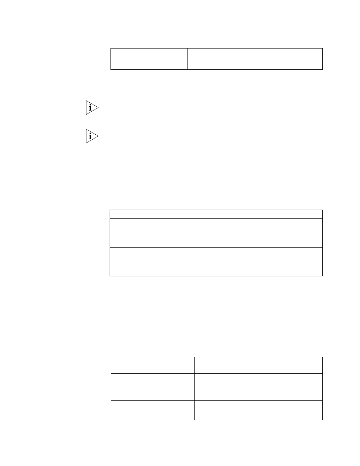
78 CHAPTER 5: CONFIGURING NETWORK MANAGEMENT
Delete a user from the SNMP
group
undo snmp-agent usm-user { v1 username
groupname | v2c username groupname | v3
username groupname }
By default, SNMPv3 is used. The default view name in the system is ViewDefault,
and OID of which is 1.3.6.1. SNMP group has only the read-only authority by
default.
If SNMPv1/SNMPv2c is used, the community name or SNMPv1/SNMPv2c groups
and users should be configured. If SNMPv3 is used, SNMPv3 groups and users
should be configured.
Before configuring an SNMP group, you should first define the view , which will be
used for configuring the SNMP group. When configuring the community name,
however, specifying a view is optional.
3 Configure information of router administrator
You should correctly configure information describing location and management
of the local equipment so that the network administrator can contact the
equipment administrator.
Perform the following configurations in system view.
Table 59 Configure information of router administrator
Operation Command
Set the administrator ID and the contact method snmp-agent sys-info contact
string
Restore the default administrator ID and the
contact method
Set router location information snmp-agent sys-info location
Restore the default router location undo snmp-agent sys-info
undo snmp-agent sys-info
contact
string
location
4 Configure traps to be sent by the router
Traps are unsolicited messages that a managed device sends to an NMS for
reporting some urgent and significant events. When a router works as a managed
device, you should configure the destination and source addresses of the trap that
it will send. The destination address is the IP address of the NMS receiving the trap
packet, and the source address is the address of the local router, that is, the
address of an interface on the local router.
Perform the following configurations in system view.
Table 60 Configure the traps to be sent by the router
Operation Command
Enable the router to send traps snmp-agent trap enable [ trap-type ]
Disable the router to send traps undo snmp-agent trap enable
Specify the interface whose address
is bound as the source address in
the trap messages
Remove the interface whose
address is bound as the source
address in the trap messages
snmp-agent trap source interface-type
interface-number
undo snmp-agent trap source
Page 83

SNMP Overview 79
Set the address of host receiving
the traps
Remove the address of host
receiving the traps
Set the message queue length of
traps destined to a host
Restore the default message queue
length
Set the timeout time for traps snmp-agent trap life timeout
Restore the default timeout time for
traps
snmp-agent target-host trap address
host-addr [ port port ] [ parameters {
v1 | v2c | v3 { authentication |
noauthentication | privacy } } ]
securityname name
undo snmp-agent target-host trap address
host-addr [ port port ] securityname
name
snmp-agent trap queue-size length
undo snmp-agent trap queue-size
undo snmp-agent trap life
By default, the router is disabled to send traps.
5 Configure the maximum size of SNMP packets that the router can send/receive
Set the Max SNMP messages that can be received/sent by the agent according to
the network loading capacity.
Perform the following configurations in system view.
Table 61 Configure the maximum size of SNMP packets that the agent can send/receive
Operation Command
Set the maximum size of SNMP packets that the
agent can receive/send
Restore the default maximum size of SNMP
packets
snmp-agent packet max-size
byte-count
undo snmp-agent packet max-size
Display and Debug
SNMP
Perform the following commands in all views.
Table 62 Display and debug SNMP
Operation Command
Display the statistics of SNMP packets display snmp-agent statistics
Display the current equipment engine ID display snmp-agent
local-engineid
Display information of system location display snmp-agent sys-info
location
Display system contact information display snmp-agent sys-info
contact
Display information of snmp groups on the
router
Display information of all SNMP users in the
group user name list
Display the group names that have been
configured
Display information of the MIB views that have
been configured
Enable SNMP debugging debugging snmp-agent { headers |
display snmp-agent group
display snmp-agent usm-user
display snmp-agent community
display snmp-agent mib-view
packets | process | trap | all }
Page 84

80 CHAPTER 5: CONFIGURING NETWORK MANAGEMENT
Typical Configuration
Examples
Example 1: Configure Network Management of SNMPv1
I. Networking Requirements
In the following diagram the NMS and a router are connected via the Ethernet.
The IP addresses of NMS and the Ethernet interface on the router are respectively
129.102.149.23 and 129.102.0.1.
II. Networking Diagram
Figure 3-3Configure SNMP
e 0
129.102.0.1
NMS
Router
129.102.149.23
Ethernet
III. Configuration Procedure
1 Enable the router to support SNMP and select an SNMP version.
[Router] snmp-agent
[Router] snmp-agent sys-info version v1
2 Set the community name and access authority.
[Router] snmp-agent community public read
[Router] snmp-agent community private write
3 Set the ID of administrator, contact method and physical location of the router.
[Router] snmp-agent sys-info contact Mr.Wang-Tel:3306
[Router] snmp-agent sys-info location telephone-closet,3rd-floor
4 Enable the router to send traps to NMS (129.102.149.23) and use the community
name “public”, and set the source address in the traps to be the IP address of the
interface ethernet 0.
[Router] snmp-agent trap enable
[Router] snmp-agent target-host trap address 129.102.149.23
securityname public
[Router] snmp-agent trap source ethernet 0
5 Configure an IP address for the Ethernet interface ethernet 0.
[Router] interface ethernet 0
[Router-Ethernet0] ip address 129.102.0.1 255.255.0.0
Example 2: Configure Network Management of SNMPv3
I. Networking Requirements
■ According to the networking of Example 1, NMS is connected to the router via
the Ethernet, and their IP addresses are respectively 129.102.149.23 and
129.102.0.1.
■ SNMPv3 is required. Three SNMP groups will be configured and respectively
authorized with read-only, writing, and notifying rights. Three SNMP users
belong to the three groups respectively, and three MIB views are used as read,
write and notify views respectively.
■ Information of the network administrator is required to be configured.
Page 85

RMON Overview 81
■ Required if traps are to be sent — the IP address of the interface ethernet 0 is
the source address of the traps, and the address of the NMS is the destination
address.
II. Networking Diagram
Refer to the networking diagram of Example 1.
III. Configuration Procedure
1 Enable the router to support SNMP and select an SNMP version.
[Router] snmp-agent
2 Set SNMP groups, users and views.
[Router] snmp-agent mib-view included read_view subtree 1.3.6.1
[Router] snmp-agent mib-view included write_view subtree 1.3.6.1.5
[Router] snmp-agent mib-view excluded notify_view subtree 1.3.6.2
[Router] snmp-agent group v3 group_read noauthentication read -view
read_view
[Router] snmp-agent group v3 group_write privacy write-view
write_view
[Router] snmp-agent group v3 group_notify authentication read-view
notify_view
[Router] snmp-agent usm-user v3 user_read group_read
[Router] snmp-agent usm-user v3 user_write group_write
authentication md5 123 privacy-mod des56 asdf
[Router] snmp-agent usm-user v3 user_notify group_notify
authentication md5 qwer
3 Configure information of equipment administrator
[Router] snmp-agent sys-info contact Mr.Wang-Tel:3306
[Router] snmp-agent sys-info location telephone-closet,3rd-floor
4 Configure the router to send Traps to the host whose IP address is
129.102.149.23.
[Router] snmp-agent trap enable
[Router] snmp-agent target-host trap address 129.102.149.23
securityname user_notify parameters v3 auth
[Router] snmp-agent trap source ethernet 0
5 Configure an IP address for the Ethernet interfa ce ethernet 0
[Router] interface ethernet 0
[Router-Ethernet0] ip address 129.102.0.1 255.255.0.0
RMON Overview RMON (Remote Monitor) is a MIB defined by IETF and is the most important
enhancement for the MIB II standard. It mainly monitors the data flow in a
network segment or on the entire network. It is implemented on the basis of the
SNMP architecture (one of its strengths), including NMS and Agent running on
network equipment.
RMON Agent performs statistics of diversified flow information on the network
segments connected to the ports, such as the total messages on a network
segment within a certain period or the total of correct messages sent to a host. It
enables SNMP to monitor remote network devices more efficiently and more
actively and provides an efficient method to monitor sub-network running. This
method can help reduce communication flows between the NMS and the Agent,
Page 86

82 CHAPTER 5: CONFIGURING NETWORK MANAGEMENT
thus managing large-scale interconnection networks easily and effectively. RMON
also allows several monitors and can collect data in two ways: one is to collect
with the RMON probe — NMS directly obtains management data from an RMON
probe and controls network resources. In this way, all RMON MIB data can be
obtained. The other way is by the RMON Agent directly implanted in network
equipment (router, switch and HUB) which will become network facilities with
RMON probe function. NMS exchanges data information with them and collects
network management information through SNMP basic commands. However,
limited by equipment resources, not all RMON MIB data can be obtained this way.
In most cases, only four groups of information can be collected. Currently, the
3Com Router 1.x implements RMON in the second way.
RMON-MIB is composed of a group of statistics data, analysis data and diagnosis
data. Standard MIB not only provides a lot of the original port data of the
managed object, but it provides statistics data and calculation results of a network
segment. By running SNMP Agent supporting RMON on the network monitor,
NMS can obtain the overall flow, error statistics, and performance statistics of the
network segment, that connects the interfaces of managed network equipment
so as to fulfill network management. An RMON application example is shown
below:
Configure RMON on the
Router
Figure 36 Schematic diagram of RMON application
Console with RMON
Router
FDDI
Backbone
Internet
Bridge
With RMON function
Router
Bridge
Ethernet
Router
Ethernet
PC with RMON
Ethernet
The value includes three managed objects. With enhanced RMON alarm group
function, if a sample is found to cross the threshold, which has been configured,
RMON Agent will report to NMS so as to avoid a lot of query messages of the
NMS.
To configure RMON after SNMP, first configure RMON command lines on the
3Com Router series. Then enable RMON statistics before NMS can be used to
monitor network traffic and perform network management.
RMON configuration includes:
Page 87

RMON Overview 83
■ Enable RMON statistics of Ethernet interface
1 Enable RMON statistics of Ethernet interface
After enabling RMON statistics of an Ethernet interface, the router will perform
the statistics of the packet incoming and outgoing through this interface. After
disabling it, the router will not perform the statistics of the packet incoming and
outgoing through this interface.
Perform the following task in Ethernet interface view.
Table 63 Enable RMON statistics of an Ethernet interface
Operation Command
Enable RMON statistics of an Ethernet interface rmon promiscuous
Disable RMON statistics of an Ethernet interface undo rmon promiscuous
RMON statistics is disabled by default.
This command cannot be used in Sub-interface view.
RMON Configuration
Examples
Enable RMON statistics
I. Networking Requirement
To ensure that the router can detect the packet whose destination is another
router from the Ethernet interface, the interface should be added in the DLSw
bridge set. Otherwise, the router only performs statistics for frames with this
router as the destination.
II. Networking Diagram:
Figure 37 Enable RMON statistics
Ethernet
host1
129.1.1.111/24
host2
129.1.1.112/24
129.1.1.100/
24
A(tested rout er)
202.38.165.1/24
202.38.165.2/24
129.2.2.200/
B
24
host3
129.2.2.222/24
III. Configuration Procedure
Configure the 3Com Router
1 Configure address and route of host1, host2, host3, routerA and routerB. Make
sure they can ping through each other. Specific operation is omitted here.
2 Add Ethernet interface Ethernet 0 to DLSw bridge set.
[RouterA] interface ethernet 0
[RouterA-Ethernet0] bridge-set 1
3 Enable RMON statistics of Ethernet 0
Page 88

84 CHAPTER 5: CONFIGURING NETWORK MANAGEMENT
[RouterA] interface ethernet 0
[RouterA-Ethernet0] rmon promiscuous
Page 89

DISPLAY AND DEBUGGING TOOLS
6
This chapter includes information on the following topics:
■ Display Command Set
■ Debugging Command Set
■ Test Tool of Network Connection
■ Log Function
Display Command Set With display commands, the system status and system information can be
viewed.
functionality:
■ The command to display system configuration information
■ The command to display system running status
display commands can be divided as follows according to the
■ The command to display system statistic information
The following commands can be used to display related information of the whole
system in all views. Please see related chapters in this manual for specific
display
commands.
Table 64 Commands to display information of the whole system
Operation Command
Display current terminal user. display client
Display the system clock display clock
Display the current memory type display configfile
Display states of various debugging switches display debugging
Display the history record of input command display history-command
Display the router name display systname
Display current configuration information of the
system
Display initial configuration information of the system
stored in router Flash
Display primary system configuration information display tech-support [ page
Display registered terminal user display user
Display version information of system display version
display
current-configuration
display saved-configuration
]
Debugging Command
Set
The command line interface of the 3Com Router 1.x provides abundant
debugging commands, almost corresponding to all the protocols supported by the
router, helping the user to diagnose and eliminate network faults.
Page 90

86 CHAPTER 6: DISPLAY AND DEBUGGING TOOLS
Two switches control the output of the debugging information:
■ Debugging switch, which controls whether to test a certain
function/module/protocol.
■ Syslog output direction switch, which controls outputting the debugging
information to the control console, Telnet terminal or internal buffer or log
host.
The following is part of the common debugging commands. For more specific
debugging commands related to various protocols, please see related chapters in
this manual and the 3Com Router Command Reference Guide.
The 3Com Router provides a shortcut Ctrl+D to close the huge amount of
debugging information output by the terminal, which functions the same as the
command
Examples are omitted here. Please see relevant chapters in the 3Com Router
Command Reference Guide.
In addition, when any terminal user enables or disables the debugging, the
debugging information output on other user terminals will be affected.
undo debugging all.
Test Tool of Network
Connection
Ping Command The ping command is mainly used to check the connection of the network, i.e.
As for all link layer protocols, the debugging can be controlled according to
interfaces, so that the interference of a huge amount of redundant information
can be avoided effectively and it makes troubleshooting more convenient.
On the 3Com Router, Syslog (log system) manages the output of debugging
information and other prompt information. Before obtaining the debugging
information, you need to open the related Syslog switch. Firstly, you must use the
info-center enable command to enable Syslog function, then you can use the
info-center console or info-center monitor command to enable debugging
according to the different type of terminal, or use the
debugging
debugging
command on the Console terminal, or use info-center monitor
on the telnet terminal or dumb terminal. Refer to subsequent sections
info-center console
for introduction and detailed descriptions and commands of Syslog.
Since the output of the debugging information will affect the running efficiency of
the router, please do not turn on any debugging switches unless necessary,
especially the
debugging all command. After completing debugging, please turn
off all debugging switches.
whether the host is accessible. Ping sends Internet Control Message Packets
(ICMP) echo packets to another computer connected on the network to see
whether it echoes back. Ping is a useful command to test the connectivity of the
network and details about the journey.
Table 65 ping command
Operation Command
Page 91

Test Tool of Network Connection 87
ping supporting IP protocol ping [ip] [-Rdnqrv] [-c count] [-p pattern]
[-s packetsize] [-t timeout] { host |
ip-address }
ping supporting IPX
protocol
ping [ipx] [-n] [-v] N.H.H.H [count [,timeout
[,packetsize]]]
Please see relevant chapters in the 3Com Router Command Reference Guide for
detailed meanings of various options and parameters.
Ping supporting IP protocol
■ For each ping message sent, if the response message has not been received
when the waiting time crosses the threshold, then
Request time out is
output.
■ Otherwise, the data byte number, message sequence number, TTL, and
response time in the response message will be displayed.
■ Finally, the statistic information will be output, including the sent message
number, received response message number, percentage of messages
unresponded, and the minimum, maximum, and average values of the
response time.
Examples:
[Router]ping 202.38.160.244
The system displays:
ping 202.38.160.244 : 56 data bytes, press CTRL_C to break
Reply from 202.38.160.244 : bytes=56 sequence=1 ttl=255 time = 1ms
Reply from 202.38.160.244 : bytes=56 sequence=2 ttl=255 time = 2ms
Reply from 202.38.160.244 : bytes=56 sequence=3 ttl=255 time = 1ms
Reply from 202.38.160.244 : bytes=56 sequence=4 ttl=255 time = 3ms
Reply from 202.38.160.244 : bytes=56 sequence=5 ttl=255 time = 2ms
--202.38.160.244 ping statistics- 5 packets transmitted
5 packets received
0% packet loss
round-trip min/avg/max = 1/2/3 ms
Ping supporting IPX protocol
■ For each Ping message sent, the response information is output. “!” indicates
the response message is received, while “.” indicates not received.
■ Finally, the statistic information is output, including sent message number,
received response message number, percentage of messages unresponded,
and the minimum, maximum, and average values of the response time.
Examples:
[Router]ping ipx 2.0.0c91.f61f
The system displays:
Press CTRL_C to break
Sending 5, 100-byte IPX Echoes to 2.0.0c91.f61f, timeout is 2
seconds
Page 92

88 CHAPTER 6: DISPLAY AND DEBUGGING TOOLS
!!!!!
--2.0.0c91.f61f IPX ping statistics- 5 packets transmitted
5 packets received
0% packet loss
round-trip min/avg/max = 1/2/3 ms
tracert command (Trace
Route Command)
The trace route command helps to trace the current network path to a
destination. With
tracert command, all gateways by which the test packet
passes from the source address to the dest ination address can be displayed. It can
be used to check network connection and locate fault.
The tracert command is executed as follows: first, send a packet with TTL 1, and
the first hop returns an ICMP error message, indicating that this packet cannot be
sent (for TTL timeout). Then, this packet is re-sent with TTL added by 1 (namely 2).
Similarly , the next hop r eturns TTL timeout. In this way, the procedure continues till
the destination is reached. The purpose of these procedures is to record the source
address of each ICMP TTL timeout message, so as to provide the path by which an
IP packet has to pass to reach the destination address.
The following command can be executed in any command modes:
Table 66 tracert command
Operation Command
Display the path from the source
address to the destination
address
tracert [ -a ip-address ] [ -f first_TTL ]
[ -m max_TTL ] [ -p port ] [ -q nqueries ]
[ -w timeout ] host
Please see relevant chapters in the 3Com Router Command Reference Guide for
detailed meanings of various options and parameters.
Described below are two examples to analyze the network connection with
tracert command. In the former example, network connection is correct, while in
the latter, network connection is faulty.
[Router]tracert 35.1.1.48
Trace route to nis.nsf.net (35.1.1.48), 30 hops max, 56 byte packet
1 helios.ee.lbl.gov (128.3.112.1) 19 ms 19 ms 0 ms
2 lilac-dmc.Berkeley.EDU (128.32.216.1) 39 ms 39 ms 19 ms
3 ccngw-ner-cc.Berkeley.EDU (128.32.136.23) 39 ms 40 ms 39 ms
4 ccn-nerif22.Berkeley.EDU (128.32.168.22) 39 ms 39 ms 39 ms
5 128.32.197.4 (128.32.197.4) 40 ms 59 ms 59 ms
6 131.119.2.5 (131.119.2.5) 59 ms 59 ms 59 ms
7 129.140.70.13 (129.140.70.13) 99 ms 99 ms 80 ms
8 129.140.71.6 (129.140.71.6) 139 ms 239 ms 319 ms
9 129.140.81.7 (129.140.81.7) 220 ms 199 ms 199 ms
10 nic.merit.edu (35.1.1.48) 239 ms 239 ms 239 ms
The above results indicate which gateways (1~9) are passed from the source
address to the destination address. That is very useful to network analysis.
[Router]tracert 18.26.0.115
traceroute to allspice.lcs.mit.edu (18.26.0.115), 30 hops max
1 helios.ee.lbl.gov (128.3.112.1) 0 ms 0 ms 0 ms
2 lilac-dmc.Berkeley.EDU (128.32.216.1) 19 ms 19 ms 19 ms
Page 93

Log Function 89
3 lilac-dmc.Berkeley.EDU (128.32.216.1) 39 ms 19 ms 19 ms
4 ccngw-ner-cc.Berkeley.EDU (128.32.136.23) 19 ms 39 ms 39 ms
5 ccn-nerif22.Berkeley.EDU (128.32.168.22) 20 ms 39 ms 39 ms
6 128.32.197.4 (128.32.197.4) 59 ms 119 ms 39 ms
7 131.119.2.5 (131.119.2.5) 59 ms 59 ms 39 ms
8 129.140.70.13 (129.140.70.13) 80 ms 79 ms 99 ms
9 129.140.71.6 (129.140.71.6) 139 ms 139 ms 159 ms
10 129.140.81.7 (129.140.81.7) 199 ms 180 ms 300 ms
11 129.140.72.17 (129.140.72.17) 300 ms 239 ms 239 ms
12 * * *
13 128.121.54.72 (128.121.54.72) 259 ms 499 ms 279 ms
14 * * *
15 * * *
16 * * *
17 * * *
18 ALLSPICE.LCS.MIT.EDU (18.26.0.115) 339 ms 279 ms 279 ms
The above results indi cate which ga teways (1~17) ar e passed fr om the source host
to the destination host, and which gateways are faulty (12, 14, 15, 16 and 17).
Log Function This section describes the various attributes that form the log function and how to
configure on the router.
Syslog Overview The 3Com Router 1.x is configured with Syslog (log system). As an indispensable
part of the 3Com Router 1.x, Syslog serves as the information junction of the
3Com Router 1.x system software module. The log system is responsible for most
of the information output and can perform detailed classification so as to filter
information effectively. In combination with the
debugging command, the system
provides powerful support for the network administrator and development staff to
monitor the network running state and diagnose the network faults.
The Syslog of the 3Com Router 1.x features the following:
■ Support log output in four directions, i.e. to the control console (Console), to
the telnet terminal and the dumb terminal (Monitor), to the internal buffer
(Buffer), and to the log host (Loghost).
■ Log information is divided into eight levels according to the importance and
filter based on the levels.
■ Information is classified according to the source modules and filter based on
the modules.
■ Information can be output in Chinese or English.
Configure Syslog The configuration tasks of Syslog include:
■ Set the direction of Syslog outputting log information
■ Set the Severity of log information
■ Set the Filter of log information
■ Turn on/off Syslog
Page 94

90 CHAPTER 6: DISPLAY AND DEBUGGING TOOLS
Set the direction of syslog outputting log information
As described before, Syslog of the 3Com Router 1.x can output various lo g
information in four directions:
■ Output log information to local control console via Console port
■ Output log information to remote Telnet terminal or dumb terminal. This
function is helpful to remote maintenance.
■ Allocate proper router buffer to record log information.
■ By configuring the log host, log information is directly sent by Syslog to the log
host and then saved as file for later view.
Please enter the following commands in system view.
Figure 38 Set the direction of syslog output log information
Operation Command
Enable to output log information to local control
console
Disable to output log information to local control
console
Enable to output log information to the terminal info-center monitor
Disable to output log information to the terminal undo info-center monitor
Enable to output log information to internal
buffer
Disable to output log information to internal
buffer
Define the size of internal buffer of output log
information
Enable to output log information to the log host info-center loghost
Disable to output log information to the log host undo info-center loghost
Change the language mode (Chinese | English) of
output log information
info-center console
undo info-center console
info-center logbuffer
undo info-center logbuffer
info-center logbuffer size
info-center { console | monitor
| logbuffer | loghost} {
chinese | english }
Here, Console and Monitor stand for default output directions.
The setting of output direction of the log information will be effective only if
Syslog is turned on.
The settings of the output log information in four directions are independent. The
shutdown of an output in any direction will not affect the output in other
directions.
When there are multiple telnet users or dumb terminal users simultaneously,
various users share the same configuration parameters, which include the filtering
setting based on the module, Chinese/English selection and severity threshold.
When a user changes the values of these parameters, other user terminals will also
be affected. At this time, the
undo info-center monitor command can only turn
off the log information output on the respective terminal. Therefore, to turn off
the log information outputs of all telnet terminals and dumb terminals, please use
undo info-center monitor all command.
the
Page 95

Log Function 91
Set Severity of Log Information
Syslog is divided into 8 levels according to the Severity (or priority) of the
information. The rule to filter the log information according to the level is: the
more urgent the log information is, the less severe it will be. The log information
with severity higher than the set threshold is forbidden to be output. Only the log
information with severity no higher than this threshold can be output.
Perform the following task in system view.
Table 67 Enable to output log information with priority
Operation Command
Enable to output log information
with priority to local control
console
Enable to output log information
with priority to the terminal
Enable to output log information
with priority to internal buffer
Enable to output log information
with priority to the log host
Disable to output log information
with priority to the log host.
info-center console {emergencies |alerts
| critical | errors | warnings |
notifications |informational |debugging}
info-center monitor {emergencies |alerts
| critical | errors | warnings |
notifications |informational |debugging}
info-center logbuffer {emergencies
|alerts | critical | errors | warnings |
notifications |informational |debugging}
info-center loghost <0-9>
{local<0-7>|ip-address} {emergencies
|alerts | critical | errors | warnings
notifications |informational |debugging}
undo info-center { console | monitor |
logbuffer | loghost}
Sylog-defined severity is as follows:
Table 68 Syslog-defined severity
Severity Descriptions
Emergencies (0) Most severe/emergent fault
Alerts (1) Fault needs to be corrected immediately
Critical (2) Major fault
Errors (3) Noticeable but not major fault
Warnings (4) Cautions, it is possible there may be a fault
Notifications (5) Information needs to pay attention to
Informational (6) Ordinary prompt information:
Debugging (7) Debugging information
Set Filter of Log Information
In different output modes, the Filter can be set according to the source of log
information. Only the log information complying with the Filter definition can be
output.
Please enter the following commands in system view.
Table 69 Set filter of the log information
Operation Command
Set Filter of the control console info-center console filter module
Delete Filter of the control console undo info-center console filter
Page 96

92 CHAPTER 6: DISPLAY AND DEBUGGING TOOLS
Set terminal Filter info-center monitor filter module
Delete terminal Filter undo info-center monitor filter
Set Filter of internal buffer info-center logbuffer filter module
Delete Filter of terminal buffer undo info-center logbuffer filter
Set Filter of log host info-center loghost <0-9> { local<0-7>
Delete Filter of log host undo info-center loghost <0-9> {
Here, module stands for the module name. Only the log information related to a
specified module can be filtered and output.
Turn on/turn off syslog
Please enter the following commands in system view.
Table 70 Turn on/turn off syslog
Operation Command
Turn on Syslog info-center enable
Turn off Syslog undo info-center enable
| ip-address } filter module
local<0-7> | ip-address } filter
Display and Debug
Syslog
Typical Syslog
Configuration Example
When Syslog is turned on, the performance of the system will be affected due to
the information classification and output - especially when processing a large
amount of information.
Perform the following configuration in all views.
Table 71 Display and debug syslog
Operation Command
Display basic configuration information of Syslog display info-center
Display internal buffer information of Syslog display info-center logbuffer
Configuration of Log Host
The configuration, implemented on SunOS 4.0, is almost the same as that
performed on the Unix operating system of other manufacturers.
1 Execute following commands as root (supervisor)
#mkdir /var/log/Router
#touch /var/log/Router/config
#touch /var/log/Router/security
2 Edit the file /etc/syslog.conf as the root and add the following selector/action
pairs.
#Router configuration messages
Local4.crit /var/log/Router/config
When editing /etc/syslog.conf, note the following:
■ The comments can only be in separate lines, beginning with character #.
■ The selector/action pairs must be separated with one Tab instead of a space.
■ There must not be redundant spaces behind the file name.
Page 97

Log Function 93
3 When log files like config and security are created and /etc/syslog.conf file is
modified, an HUP will be sent to the system daemon, Syslogd, by executing the
following commands to make Syslogd re-read its configuration file
/etc/syslog.conf.
#ps -ae | grep syslogd
147
#kill -HUP 147
After the above operations, the router can record information in relevant log files.
Configure Facility (facility name), Severity (severity threshold), Filter, and
syslog.conf file to make a detailed classification of information, so as to filter the
information.
Syslog Configuration Example
■ Configure log information output of the control console.
1 Turn on the log system
[Router]info-center enable
2 Configure the log information output of the control console, severity ranging
between emergencies ~ debugging, and do not filter the log information output
of PPP module.
[Router]info-center console
[Router]info-center console debugging
3 Turn on debugging switch of PPP module.
[Router]debug ppp all
■ Configure the log host
The router-side configuration is as follows:
1 Turn on the log system
[Router]info-center enable
2 Use the host with IP address of 10.110.12.119 as the log host, set the severity
threshold to informational, and choose English as the output language.
[Router]info-center loghost 10.110.12.119 language english
Please see “Configuration of log host” for the host-side configuration.
Page 98

94 CHAPTER 6: DISPLAY AND DEBUGGING TOOLS
Page 99

7
POS TERMINAL ACCESS SERVICE
This chapter contains information on the following topics:
■ POS Access Service Overview
■ POS Access Service Configuration
■ Display and Debug POS Access
■ Typical Configuration Example of POS Access Se rvice
POS Access Service
Overview
Point of Sale (POS) service is a type of smart card service widely used in shopping
malls, gas stations, and so on. It links the POS terminal device at the commercial
client (located in shopping mall or gas station) to the bank card accounting system
to provide service.
The POS terminal device is widely used in the fields of commerce, finance,
taxation, and so on. The earlier POS terminal devices worked independently in
different b anks, and t hey could n ot communicat e with each ot her. The technology
based on a shared POS access service has solved this problem and makes it
possible to use different bank cards on the same POS.
The POS terminal is connected to the transaction center in two ways, namely,
through dial-up POS access and POS network access.
Dial-up POS Access
In the dial-up POS access mode, after responding to the smart card, the POS
terminal device will synchronously or asynchr onously di al up with the built-in
modem. Thus the POS terminal device at the commercial client accesses the bank
card accounting system. In this case, the 3Com Router series providing POS access
service can be placed at the commercial client side. The routers can be connected
to the front end processor via the WAN. They can also be connected to the front
end processor of the bank via the asynchronous interface or Ethernet port.
The following figure shows the networking diagram of the typical dial-up POS
access.
Figure 39 Dial-up access when the POS access router is located at the FEP side
Serial port
Ethernet
interface
UNIX FEP
POS terminal
PSTN
FCM
Router
Quidway
Page 100
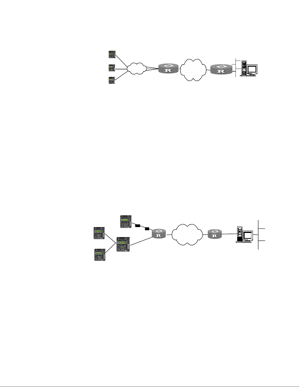
96 CHAPTER 7: POS TERMINAL ACCESS SERVICE
Figure 40 Dial-up access when the POS access router is located at the commercial client
side
POS terminal
POS terminal
POS terminal
Due to the way POS access service usually operates, that is, low speed, high
frequency and small traffic, it is rather sensitive to the dial-up connection time and
requires the interface board for fast dial-up function. However, the present
common PC modem cannot meet the response time requirements of 10 to 20
seconds. At present, most POS equipment manufacturers use the special modem
chip that supports fast connection to implement the function. The FCM card of
the 3Com Router series is a fast handshaking modem specially designed for POS
dial-up access service.
POS Network Access
In the POS network access mode, the router providing POS access service is
located at the commercial client end and helps all the POS terminals access the
3Com Router series. The router located at the FEP side can be any router and
communicates with the 3Com Router series through X.25, FR, DDN, ISDN or
modem.
PSTN/
PBX
FCM
Router
Quidway
PSTN/ISDN
X.25/FR/DDN
Router
Router
UNIX FEP
The following figure shows the netw or king of typical POS network access.
Figure 41 Access mode when the POS access router located at the commercial client end
RS-232
RS-232
Long line
drive
Router
Quidway
PSTN, ISDN
X.25,FR,DDN
Router
Serial
port
Ethernet
interface
UNIX FEP
POS1
POS2
RS-485
POS
POS
concentrator
In the POS network access mode, 3Com Router series can be connected to the
POS terminal in the following two ways:
■ Directly connect the POS RS-232 connector with the asynchronous interface
(including the asynchronous mode of the synchronous/asynchronous interface)
of the 3Com Router series. If the distance between them exceeds 15 meters, it
will be necessary to install a long-line-driver at each end of the connection line.
The valid connection distance of a pair of passive long-line-drivers is about
1200 meters.
■ Set up an RS-485 network with the POS terminal device and POS concentrator,
then connect the RS-232 connector of the POS concentrator with the
asynchronous interface of the 3Com Router series. The 3Com Router series
communicate on the egress port in the same way as the first connection
method. Access in this way can save the router interface source greatly.
The advantages of POS network access are as follows:
 Loading...