

Page 1

Switch 7750
Configuration Guide
Version 3.1.5
http://www.3com.com/
Published August 2005
Part No.10014298
Page 2

3Com Corporation
350 Campus Drive
Marlborough, MA
01752-3064
Copyright © 2005, 3Com Corporation. All rights reserved. No part of this documentation may be reproduced
in any form or by any means or used to make any derivative work (such as translation, transformation, or
adaptation) without written permission from 3Com Corporation.
3Com Corporation reserves the right to revise this documentation and to make changes in content from time
to time without obligation on the part of 3Com Corporation to provide notification of such revision or change.
3Com Corporation provides this documentation without warranty, term, or condition of any kind, either
implied or expressed, including, but not limited to, the implied warranties, terms or conditions of
merchantability, satisfactory quality, and fitness for a particular purpose. 3Com may make improvements or
changes in the product(s) and/or the program(s) described in this documentation at any time.
If there is any software on removable media described in this documentation, it is furnished under a license
agreement included with the product as a separate document, in the hard copy documentation, or on the
removable media in a directory file named LICENSE.TXT or !LICENSE.TXT. If you are unable to locate a copy,
please contact 3Com and a copy will be provided to you.
UNITED STATES GOVERNMENT LEGEND
If you are a United States government agency, then this documentation and the software described herein
are provided to you subject to the following:
All technical data and computer software are commercial in nature and developed solely at private expense.
Software is delivered as “Commercial Computer Software” as defined in DFARS 252.227-7014 (June 1995)
or
as a “commercial item” as defined in FAR 2.101(a) and as such is provided with only such rights as are
provided in 3Com’s standard commercial license for the Software. Technical data is provided with limited
rights only as provided in DFAR 252.227-7015 (Nov
applicable. You agree not to remove or deface any portion of any legend provided on any licensed program
or documentation contained in, or delivered to you in conjunction with, this User Guide.
Unless otherwise indicated, 3Com registered trademarks are registered in the United States and may or may
not be registered in other countries.
3Com, the 3Com logo, are registered trademarks of 3Com Corporation.
Intel and Pentium are registered trademarks of Intel Corporation. Microsoft, MS-DOS, Windows, and
Windows NT are registered trademarks of Microsoft
States and other countries, licensed exclusively through X/Open Company, Ltd.
All other company and product names may be trademarks of the respective companies with which they are
associated.
1995) or FAR 52.227-14 (June 1987), whichever is
Corporation. UNIX is a registered trademark in the United
Page 3

CONTENTS
ABOUT THIS GUIDE
Conventions 9
SYSTEM ACCESS
Product Overview 11
Features 11
Configuring the Switch 7750 12
Setting Terminal Parameters 13
Configuring Through Telnet 16
Configuring Through a Dial-up Modem 18
Configuring the User Interface 20
Command Line Interface 28
Command Line View 28
Features and Functions of the Command Line 31
PORT CONFIGURATION
Ethernet Port Overview 35
Configuring Ethernet Ports 35
Troubleshooting VLAN Port Configuration 42
Configuring Link Aggregation 42
Types of Link Aggregation 43
Load Sharing 45
Configuring Link Aggregation 46
VLAN CONFIGURATION
VLAN Overview 53
Configuring VLANs 53
Common VLAN Configuration Tasks 54
Configuring Port-Based VLANs 57
Configuring Protocol-Based VLANs 57
Configuring GARP/GVRP 61
Configuring GVRP 63
NETWORK PROTOCOL OPERATION
Configuring IP Address 67
Page 4

Subnet and Mask 68
Configuring an IP Address 68
Troubleshooting an IP Address Configuration 70
Configuring Address Resolution Protocol (ARP) 70
Configuring ARP 71
DHCP Relay 72
Configuring DHCP Relay 73
Troubleshooting a DHCP Relay Configuration 76
IP Performance 77
Configuring TCP Attributes 77
Configuring Special IP Packet Transmission to the CPU 77
Configuring L3 Broadcast Forwarding 78
Displaying and Debugging IP Performance 78
Troubleshooting IP Performance 79
IP ROUTING PROTOCOL OPERATION
IP Routing Protocol Overview 81
Selecting Routes Through the Routing Table 82
Routing Management Policy 83
Static Routes 84
Configuring Static Routes 85
Troubleshooting Static Routes 88
RIP 89
Configuring RIP 90
Troubleshooting RIP 98
IP Routing Policy 99
Routing Information Filters 99
Configuring an IP Routing Policy 100
Troubleshooting Routing Policies 104
Route Capacity 105
Configuring Route Capacity 105
MULTICAST PROTOCOL
IP Multicast Overview 109
Multicast Addresses 110
IP Multicast Protocols 112
Forwarding IP Multicast Packets 113
Applying Multicast 114
Configuring Common Multicast 114
Configuring Common Multicast 114
Configuring IGMP 116
Configuring IGMP 117
IGMP Snooping 124
Configuring IGMP Snooping 127
Troubleshooting IGMP Snooping 129
Configuring PIM-DM 130
Page 5

Configuring PIM-DM 131
Configuring PIM-SM 136
PIM-SM Operating Principles 136
Preparing to Configure PIM-SM 137
Configuring PIM-SM 138
GMRP 146
Configuring GMRP 146
QOS/ OPERATION
ACL Overview 149
Filtering or Classifying Data Transmitted by the Hardware 149
Filtering or Classifying Data Transmitted by the Software 150
ACL Support on the Switch 7750 150
Configuring ACLs 151
Configuring the Time Range 151
Selecting the ACL Mode 151
Defining an ACL 151
Activating an ACL 154
ACL Configuration Examples 155
Access Control 155
Basic ACL 156
Link ACL 157
Configuring QoS 157
Qos Concepts 158
Configuring QoS 161
QoS Configuration Examples 168
Configuring ACL Control 175
Configuring ACL Control for TELNET Users 176
Configuring ACL Control for SNMP Users 177
STP OPERATION
STP Overview 181
Configuring STP 181
Designating Switches and Ports 182
Calculating the STP Algorithm 182
Generating the Configuration BPDU 183
Selecting the Optimum Configuration BPDU 183
Designating the Root Port 183
Configuring the BPDU Forwarding Mechanism 185
MSTP Overview 186
MSTP Concepts 186
MSTP Principles 189
Configuring MSTP 189
Configuring the MST Region for a Switch 190
Specifying the Switch as Primary or Secondary Root Switch 191
Configuring the MSTP Running Mode 192
Page 6

Configuring the Bridge Priority for a Switch 193
Configuring the Max Hops in an MST Region 194
Configuring the Switching Network Diameter 194
Configuring the Time Parameters of a Switch 195
Configuring the Max Transmission Speed on a Port 196
Configuring a Port as an Edge Port 197
Configuring the Path Cost of a Port 198
Configuring the Priority of a Port 200
Configuring the Port Connection with the Point-to-Point Link 201
Configuring the mCheck Variable of a Port 202
Configuring the Switch Security Function 202
Enabling MSTP on the Device 204
Enabling or Disabling MSTP on a Port 204
Displaying and Debugging MSTP 205
Digest Snooping 205
Configuring Digest Snooping 205
AAA AND RADIUS OPERATION
IEEE 802.1x 207
802.1x System Architecture 207
Configuring 802.1x 209
Implementing the AAA and RADIUS Protocols 215
Configuring AAA 217
Configuring the RADIUS Protocol 220
Configuring HWTACACS 230
Displaying and Debugging the AAA, RADIUS, and HWTACACS Protocols 237
AAA, RADIUS, and HWTACACS Protocol Configuration Examples 238
Configuring FTP/Telnet User Authentication at Remote RADIUS Server 238
Configuring FTP/Telnet User Authentication at the Local RADIUS Server 239
Configuring the FTP/Telnet User Authentication at a Remote TACACS Server 239
Dynamic VLAN with RADIUS Server Configuration Example 240
Troubleshooting AAA, RADIUS, and HWTACACS Configurations 241
SYSTEM MANAGEMENT
File System 243
Using a Directory 243
Managing Files 244
Formatting Storage Devices 244
Setting the Prompt Mode of the File System 244
Configuring File Management 245
FTP 246
TFTP 248
Managing the MAC Address Table 249
Configuring the MAC Address Table 250
Managing Devices 253
Designating the APP for the Next Boot 254
Page 7

Displaying Devices 255
Maintaining and Debugging the System 255
Configuring System Basics 256
Displaying System Information and State 257
Debugging the System 257
Testing Tools for Network Connection 259
Logging Function 260
SNMP 265
SNMP Versions and Supported MIB 266
Configuring SNMP 267
RMON 274
Configuring RMON 274
NTP 278
Configuring NTP 279
NTP Configuration Examples 286
Page 8

Page 9

ABOUT THIS GUIDE
This guide describes the 3Com® Switch 7750 and how to configure it in version
3.0 of the software.
Conventions Ta bl e 1 lists icon conventions that are used throughout this book.
Ta bl e 1 Notice Icons
Icon Notice Type Description
Information
note
Information that describes important features or
instructions.
Caution Information that alerts you to potential loss of data
Warning Information that alerts you to potential personal
or potential damage to an application, system, or
device.
injury.
Ta bl e 2 lists the text conventions used in this book.
Ta bl e 2 Text Conventions
Convention Description
Screen displays This typeface represents information as
Keyboard key names If you must press two or more keys
The words “enter” and type” When you see the word “enter” in this
it appears on the screen.
simultaneously, the key names are
linked with a plus sign (+), for example:
Press Ctrl+Alt+Del
guide, you must type something, and
then press Return or Enter. Do not
press Return or Enter when an
instruction simply says “type.”
Page 10

10 ABOUT THIS GUIDE
Table 2 Text Conventions
Convention Description
Words in italics Italics are used to:
■ Emphasize a point.
■ Denote a new term at the place
where it is defined in the text.
■ Identify command variables.
■ Identify menu names, menu
commands, and software button
names. Examples:
From the Help menu, select
Contents.
Click OK.
Words in bold Boldface type is used to highlight
command names. For example, “Use
the display user-interface
command to...”
Page 11

SYSTEM ACCESS
1
This chapter covers the following topics:
■ Product Overview
■ Configuring the Switch 7750
■ Setting Terminal Parameters
■ Command Line Interface
Product Overview The 3Com Switch 7750 is a large capacity, modularized wire speed Layer 2/Layer 3
switch. It is designed for IP metropolitan area networks (MAN), large-sized
enterprise networks, and campus network users.
The Switch 7750 has an integrated chassis structure. The chassis contains a card
area, fan area, power supply area, and a power distribution area. In the card area,
there are seven slots. Slot 0 is prepared specially for the switch Fabric module. The
remaining slots are for interface modules. You can install different interface
modules for different networks; the slots support a mixed set of modules.
The Switch 7750 supports the following services:
■ MAN, enterprise/campus networking
■ Multicast service and multicast routing functions and audio and video multicast
service.
Features Ta bl e 3 lists and describes the function features that the Switch 7750 supports.
Ta bl e 3 Function Features
Features Support
VLAN VLANs compliant with IEEE 802.1Q standard
Port-based VLAN
Protocol-based VLAN
GARP VLAN Registration Protocol (GVRP)
STP protocol Spanning Tree Protocol (STP)
Multiple Spanning Tree Protocol (MSTP), compliant with IEEE
802.1D/IEEE 802.1s Standard
Flow control IEEE 802.3x flow control (full-duplex)
Back-pressure based flow control (half-duplex)
Broadcast suppression Broadcast suppression
Multicast GARP Multicast Registration Protocol (GMRP)
Internet Group Management Protocol (IGMP) Snooping
Internet Group Management Protocol (IGMP)
Protocol-Independent Multicast-Dense Mode (PIM-DM)
Protocol-Independent Multicast-Sparse Mode (PIM-SM)
Page 12

12 CHAPTER 1: SYSTEM ACCESS
RS-232 Serial port
Console port
Table 3 Function Features (continued)
Features Support
IP routing Static route
RIP V1/v2
IP routing policy
DHCP Relay Dynamic Host Configuration Protocol (DHCP) Relay
Link aggregation Link aggregation
Mirror Port-based mirroring
Security features Multi-level user management and password protection
Quality of Service (QoS) Traffic classification
Management and
maintenance
Loading and updating Loading and upgrading software using the XModem protocol
802.1X authentication
Packet filtering
AAA and RADIUS/HWTACACS
Bandwidth control
Priority
Queues of different priority on the port
Queue scheduling: supports Strict Priority Queueing (SP)
Command line interface configuration
Configuration through the console port
Remote configuration by Telnet
Configuration through dialing the modem
SNMP
System log
Level alarms
Output of the debugging information
PING and Tracert
Remote maintenance with Telnet, modem
Loading and upgrading software using the File Transfer Protocol
(FTP) and Trivial File Transfer Protocol (TFTP)
Configuring the Switch 7750
On the Switch 7750, you can set up the configuration environment through the
console port. To set up the local configuration environment:
1 Plug the DB-9 or DB-25 female plug of the console cable into the serial port of the
PC or the terminal where the switch is to be configured.
2 Connect the RJ-45 connector of the console cable to the console port of the
switch, as shown in
Figure 1 Setting Up the Local Configuration Environment Through the Console Port
Figure 1.
Console cable
Page 13
Setting Terminal Parameters 13
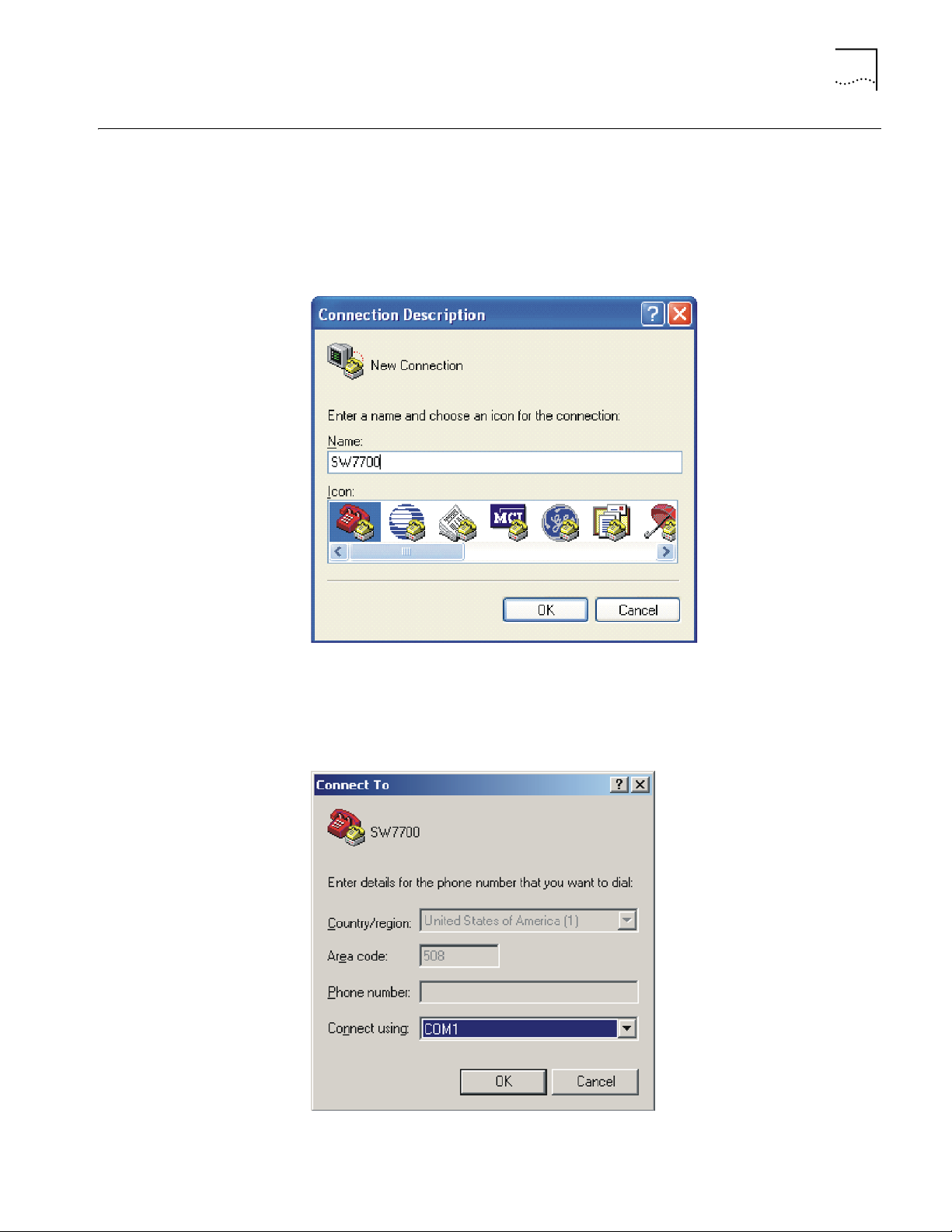
Setting Terminal Parameters
To set terminal parameters:
1 Start the PC and select Start > Programs > Accessories > Communications >
HyperTerminal. The HyperTerminal window displays the Connection Description
dialog box, as shown in
Figure 2 Set Up the New Connection
Figure 2.
2 Enter the name of the new connection in the Name field and click OK. The dialog
box, shown in
Figure 3 displays.
3 Select the serial port to be used from the Connect using dropdown menu.
Figure 3 Properties Dialog Box
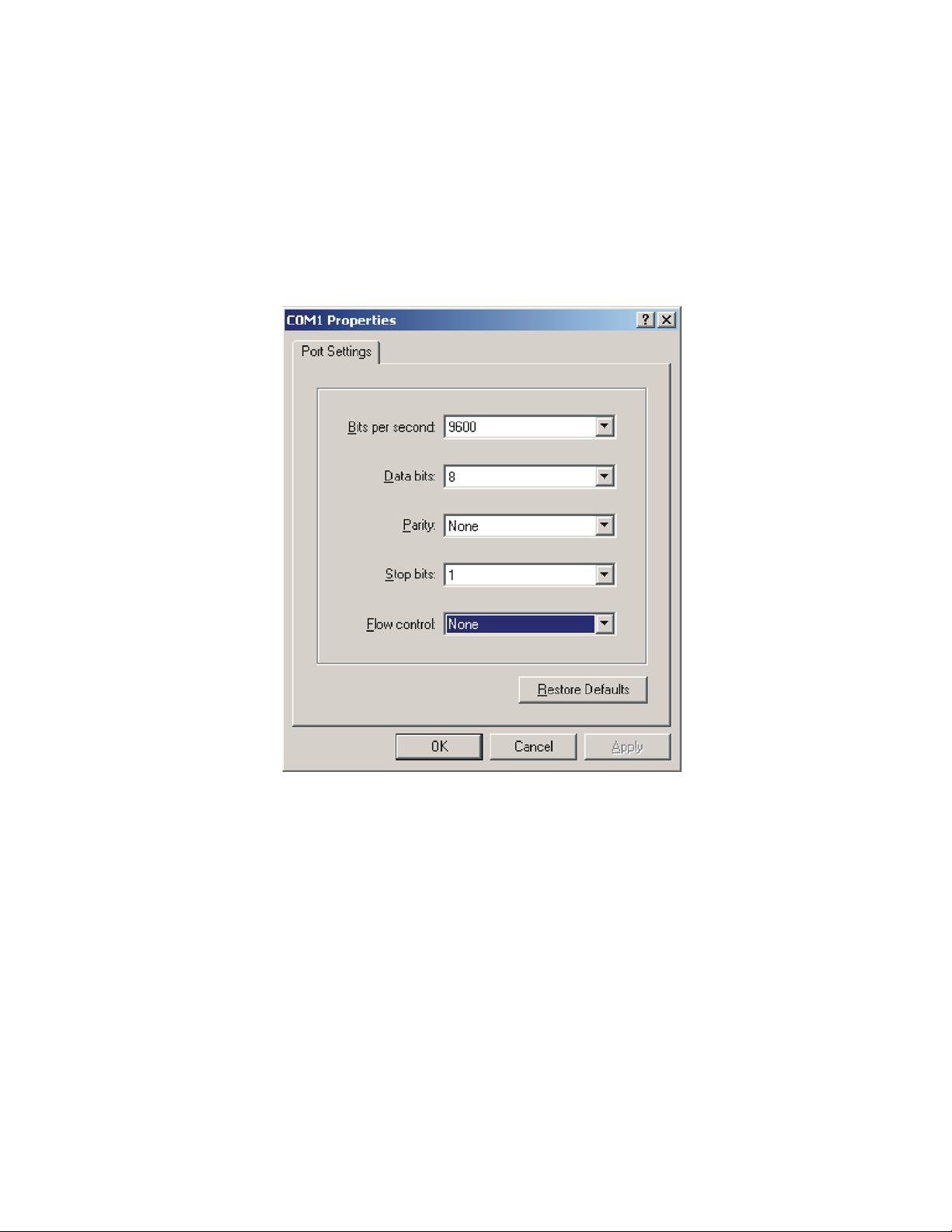
4 Click OK. The Port Settings tab, shown in Figure 4, displays and you can set serial
port parameters. Set the following parameters:
Page 14
14 CHAPTER 1: SYSTEM ACCESS
■ Baud rate = 9600
■ Databit = 8
■ Parity check = none
■ Stopbit = 1
■ Flow control = none
Figure 4 Set Communication Parameters
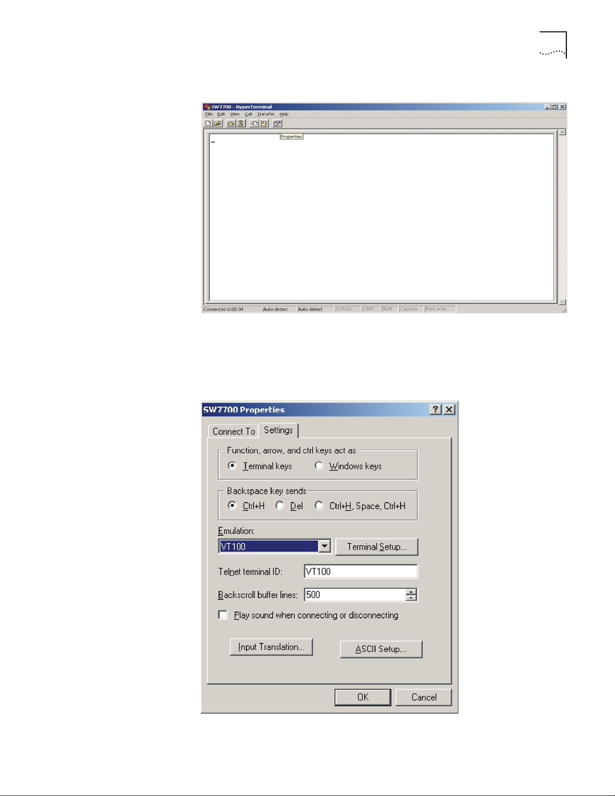
5 Click OK. The HyperTerminal dialogue box displays, as shown in Figure 5.
6 Select Properties.
Page 15
Setting Terminal Parameters 15
Figure 5 HyperTerminal Window
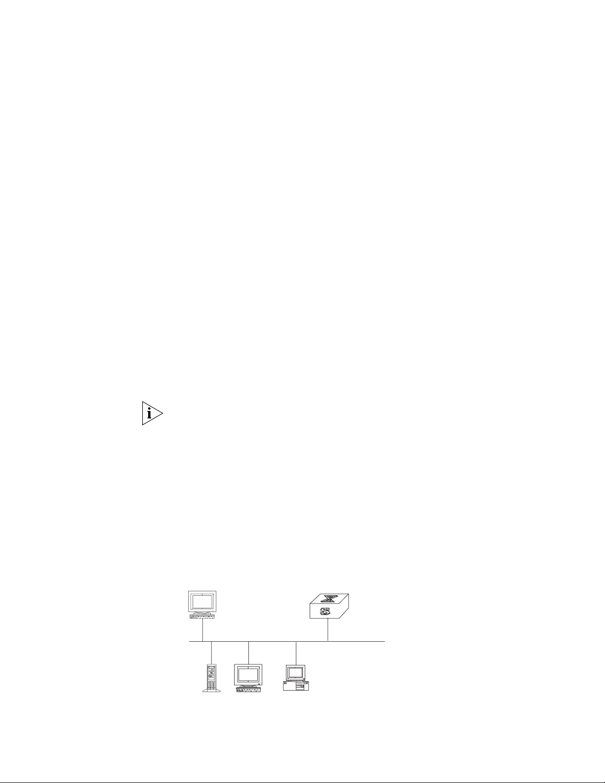
7 In the Properties dialog box, select the Settings tab, as shown in Figure 6.
8 Select VT100 in the Emulation dropdown menu.
9 Click OK.
Figure 6 Settings Tab
Page 16
16 CHAPTER 1: SYSTEM ACCESS
Setting the Terminal Parameters is described in the following sections:
■ Configuring Through Telnet
■ Configuring Through a Dial-up Modem
■ Configuring the User Interface
Configuring Through
Te ln e t
Before you can telnet to a Switch 7750 and configure it, you must:
1 Configure the IP address of a VLAN interface for the Switch 7750 through the
console port (using the
ip address command in VLAN interface view)
2 Add the port (that connects to a terminal) to this VLAN (using the port command
in VLAN view)
3 Log in to the Switch 7750
Tasks for Configuring through Telnet are described in the following sections:
■ Connecting the PC to the Switch 7750
■ Connecting Two Switch 7750 Systems
Connecting the PC to the Switch 7750
To connect the PC and Switch 7750 through Telnet:
1 Authenticate the Telnet user through the console port before the user logs in by
Te ln e t.
By default, a password is required for authenticating the Telnet user to log in the
Switch 7750. If a user logs in by Telnet without a password, the user sees the
message:
Login password has not been set!
2 Enter system view, return to user view by pressing Ctrl+Z.
<SW7750>system-view
[SW7750]user-interface vty 0 4
[SW7750-ui-vty0]set authentication password simple/cipher xxxx
(xxxx is the preset login password of Telnet user)
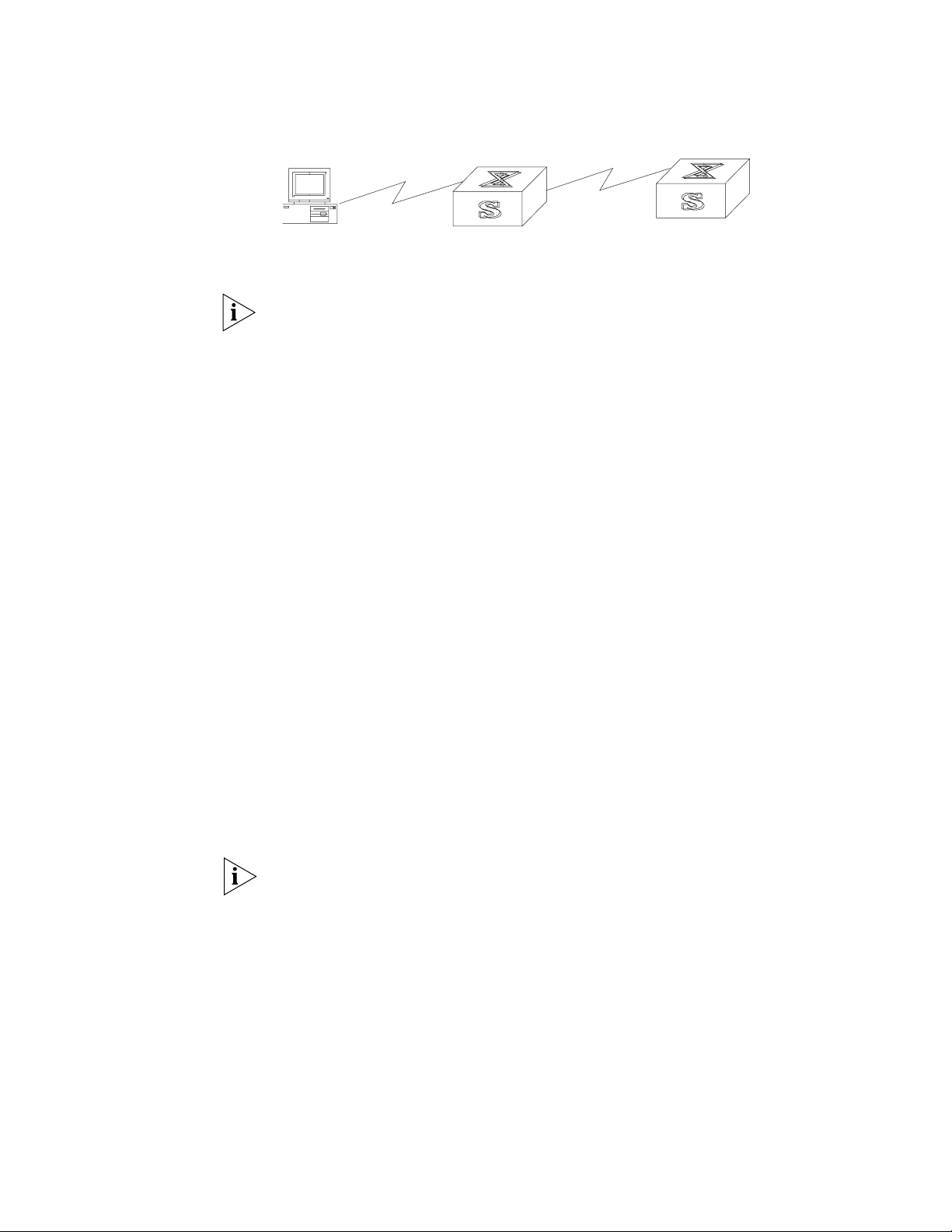
3 To set up the configuration environment, connect the Ethernet port of the PC to
that of the Switch 7750 through the LAN. See
Figure 7 Setting Up the Configuration Environment Through Telnet
Workstation
Ethernet port
Figure 7.
Ethernet
WorkstationServer
PC (for configuring
the switch through Telnet)
Page 17
Setting Terminal Parameters 17
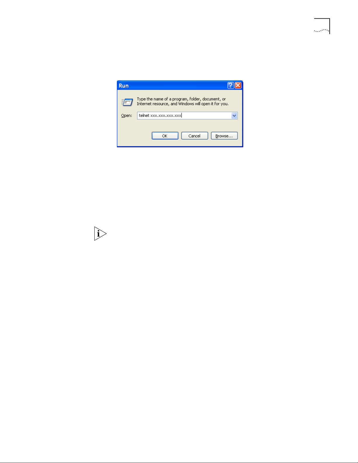
4 Run Telnet on the PC by selecting Start > Run from the Windows desktop and
entering Tel ne t in the Open field, as shown in
Figure 8 Run Telnet
Figure 8. Click OK.
The terminal displays Login authentication and prompts you for the logon
password.
5 Enter the password. The terminal displays the command line prompt (<SW7750>).
If the message, All user interfaces are used, please try later! appears,
try to reconnect later. At most, 5 Telnet users are allowed to log on to a Switch
7750 simultaneously.
6 Use the appropriate commands to configure the Switch 7750 or to monitor the
operational state. Enter
? to get immediate help. For details on specific
commands, refer to the chapters in this guide.
When configuring the Switch 7750 by Telnet, do not modify the IP address unless
necessary, because the modification might terminate the Telnet connection. By
default, after passing the password authentication and logging on, a Telnet user
can access the commands at login level 0.
Connecting Two Switch 7750 Systems
Before you can telnet the Switch 7750 to another Switch 7750, as shown in
Figure 9, you must:
1 Configure the IP address of a VLAN interface for the Switch 7750 through the
console port (using the
ip address command in VLAN interface view)
2 Add the port (that connects to a terminal) to this VLAN (using the port command
in VLAN view)
3 Log in to the Switch 7750
After you telnet to a Switch 7750, you can run the telnet command to log in and
configure another Switch 7750.
Page 18
18 CHAPTER 1: SYSTEM ACCESS
Figure 9 Provide Telnet Client Service
PC
Telnet client
Telnet server
1 Authenticate the Telnet user through the console port on the Telnet Server (Switch
7750) before login.
By default, a password is required for authenticating the Telnet user to log in the
Switch 7750. If a user logs into Telnet without password, the system displays the
following message:
Login password has not been set!
2 Enter system view, return to user view by pressing Ctrl+Z.
<SW7750>system-view
[SW7750]user-interface vty 0
[SW7750-ui-vty0]set authentication password simple/cipher xxxx (xxxx
is the preset login password of Telnet user)
3 Log in to the Telnet client (Switch 7750). For the login process, see “Connecting
the PC to the Switch 7750”.
4 Perform the following operations on the Telnet client:
<SW7750>telnet xxxx
(XXXX can be the hostname or IP address of the Telnet Server. If it is the hostname,
you must use the
ip host command to specify it.
5 Enter the preset login password. The Switch 7750 prompt (<SW7750>) displays. If
the message,
All user interfaces are used, please try later! displays, try
to connect later.
Configuring Through a
Dial-up Modem
6 Use the appropriate commands to configure the Switch 7750 or view its
operational state. Enter
? to get immediate help. For details on a specific
command, refer to the appropriate chapter in this guide.
To configure your router through a dial-up modem:
1 Authenticate the modem user through the console port of the Switch 7750 before
the user logs in to the switch through a dial-up modem.
By default, a password is required for authenticating the modem user to log in to
the Switch 7750. If a user logs in through the modem without a password, the
user sees an error message.
<SW7750>system-view
[SW7750]user-interface aux 0
[SW7750-ui-aux0]set authentication password simple/cipher xxxx (xxxx
is the preset login password of the Modem user.)
2 Using the modem command, you can configure the console port to modem mode.
[SW7750-ui-aux0]modem
3 To set up the remote configuration environment, connect the modems to a PC (or
a terminal) serial port and to the Switch 7750 console port, as shown in
Set Up
Remote Configuration Environment.
Page 19
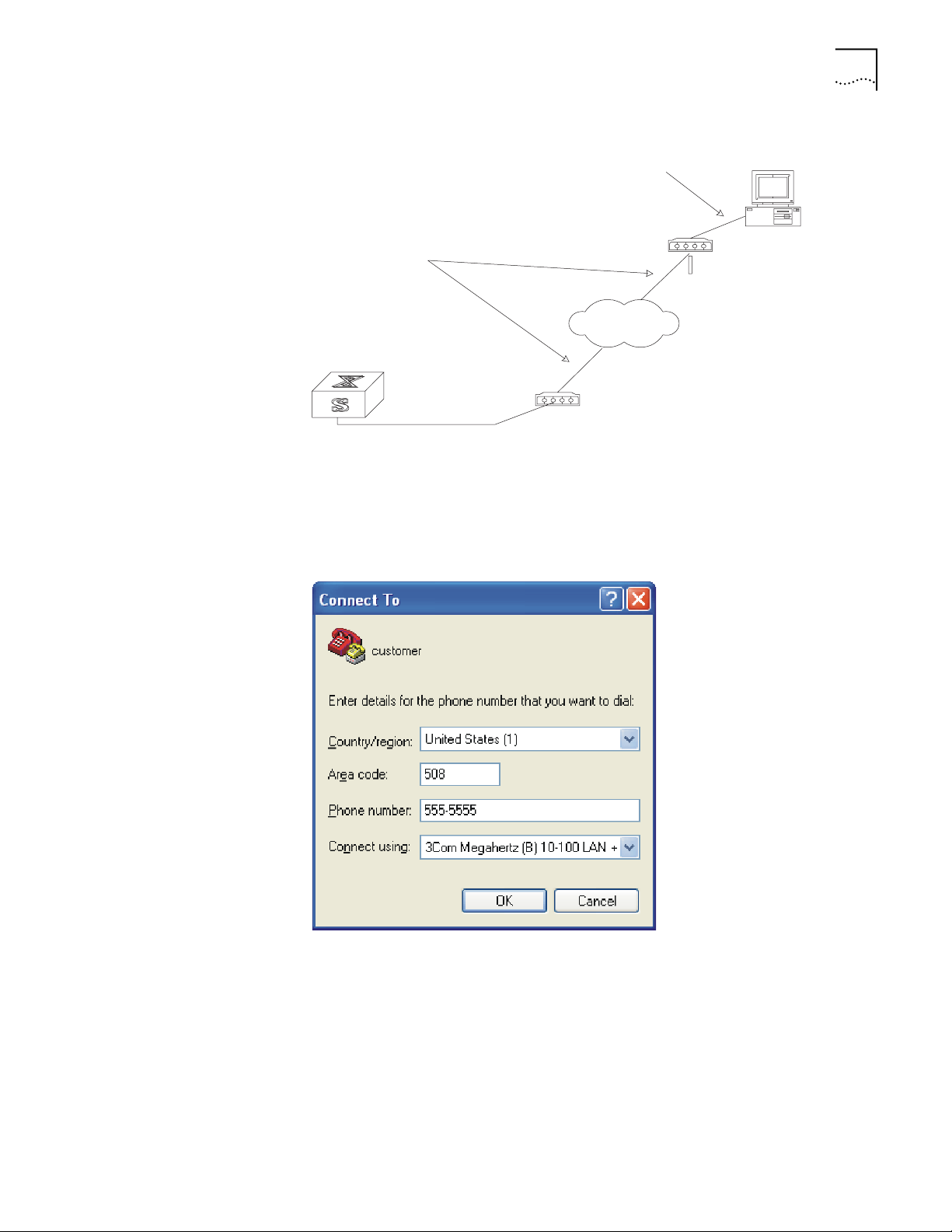
Figure 10 Set Up Remote Configuration Environment
Modem serial port line
Modem
Telephone line
PST
Modem
Setting Terminal Parameters 19
Console port
Remote telephone:
555-5555
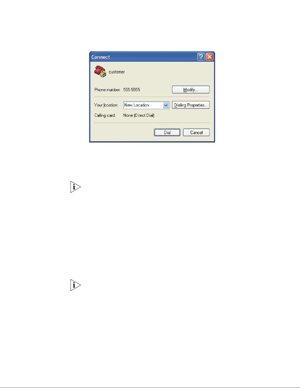
4 Dial for a connection to the switch, using the terminal emulator and modem on
the remote end. Dial the telephone number of the modem connected to the
Switch 7750. See
Figure 11 Set the Dialed Number
Figure 11 and Figure 12.
Page 20
20 CHAPTER 1: SYSTEM ACCESS
5 Enter the preset login password on the remote terminal emulator and wait for the
6 Use the appropriate commands to configure the Switch 7750 or view its
Figure 12 Dial the Remote PC
<SW7750> prompt.
operational state. Enter
? to get immediate help. For details on a specific
command, refer to the appropriate chapter in this guide.
Configuring the User
Interface
By default, after login, a modem user can access the commands at Level 0.
User interface configuration is another way to configure and manage port data.
The Switch 7750 supports the following configuration methods:
■ Local configuration through the console port
■ Remote configuration through Telnet on the Ethernet port
■ Remote configuration through a modem through the console port.
There are two types of user interfaces:
■ AUX user interface is used to log in the Switch 7750 through a dial-up modem.
A Switch 7750 can only have one AUX port.
■ VTY user interface is used to telnet the Switch 7750.
For the Switch 7750, the AUX port and Console port are the same port. There is
only the type of AUX user interface.
The user interface is numbered by absolute number or relative number.
To number the user interface by absolute number:
■ The AUX user interface is the first interface — user interface 0.
■ The VTY is numbered after the AUX user interface. The absolute number of the
first VTY is the AUX user interface number plus 1.
Page 21

Setting Terminal Parameters 21
To number the user interface by relative number, represented by interface +
number assigned to each type of user interface:
■ AUX user interface = AUX 0.
■ The first VTY interface = VTY 0, the second one = VTY 1, and so on.
Tasks for configuring the user interface are described in the following sections:
■ Entering the User Interface View
■ Configuring the Attributes of the AUX (Console) Port
■ Configuring the Terminal Attributes
■ Managing Users
■ Configuring the Attributes of a Modem
■ Configuring Redirection
■ Displaying and Debugging User Interface
Entering the User Interface View
Use the user-interface command (see Ta bl e 4) to enter a user interface view.
You can enter a single user interface view or multi-user interface view to configure
one or more user interfaces.
Perform the following configuration in system view.
Ta bl e 4 Enter User Interface View
Operation Command
Enter a single user interface view or multi user
interface views
user-interface [ type ] first-number [
last-number ]
Configuring the Attributes of the AUX (Console) Port
Use the speed, flow control, parity, stop bit, and data bit commands
Ta bl e 5) to configure these attributes of the AUX (Console) port.
(see
Perform the following configurations in user interface (AUX user interface only)
view.
Ta bl e 5 Configure the Attributes of the AUX (Console) Port
Operation Command
Configure the transmission speed on AUX
(Console) port. By default, the transmission
speed is 9600bps
Restore the default transmission speed on
AUX (Console) port
Configure the flow control on AUX (Console)
port. By default, no flow control is performed
on the AUX (Console) port
Restore the default flow control mode on AUX
(Console) port
Configure parity mode on the AUX (Console)
port. By default, there is no parity bit on the
AUX (Console) port
Restore the default parity mode undo parity
speed speed-value
undo speed
flow-control { hardware | none |
software }
undo flow-control
parity { even | mark | none | odd | space }
Page 22

22 CHAPTER 1: SYSTEM ACCESS
Table 5 Configure the Attributes of the AUX (Console) Port
Operation Command
Configure the stop bit of AUX (Console) port.
By default, AUX (Console) port supports 1
stop bit
Restore the default stop bit of AUX (Console)
port
Configure the data bit of AUX (Console) port.
By default, AUX (Console) port supports 8
data bits.
Restore the default data bit of AUX (Console)
port
stopbits { 1 | 1.5 | 2 }
undo stopbits
databits { 7 | 8 }
undo databits
Configuring the Terminal Attributes
The following commands can be used for configuring the terminal attributes,
including enabling/disabling terminal service, disconnection upon timeout,
lockable user interface, configuring terminal screen length and history command
buffer size.
Perform the following configuration in user interface view. Perform the lock
command in user view.
Enabling and Disabling Terminal Service After the terminal service is
disabled on a user interface, you cannot log in to the Switch 7750 through the
user interface. However, if a user is logged in through the user interface before
disabling the terminal service, the user can continue operation. After the user logs
out, the user cannot log in again. In this case, the user can log in to the Switch
through the user interface only when the terminal service is enabled again. Use
the commands described in
Ta bl e 6 Enabling and Disabling Terminal Service
Operation Command
Enable terminal service shell
Disable terminal service undo shell
Ta bl e 6 to enable or disable terminal service.
By default, terminal service is enabled on all the user interfaces.
Note the following points:
■ For the sake of security, the undo shell command can only be used on the
user interfaces other than the AUX user interface.
■ You cannot use this command on the user interface through which you log in.
■ You must confirm your privilege before using the undo shell command in any
legal user interface.
Page 23

Setting Terminal Parameters 23
Configuring idle-timeout By default, idle-timeout is enabled and set to 10
minutes on all the user interfaces. The
idle-timeout command is described in
Ta bl e 7.
Ta bl e 7 Idle Timeout
Operation Command
Configure idle-timeout idle-timeout minutes [ seconds ]
Restore the default idle-timeout undo idle-timeout
(idle-timeout 0 means disabling
idle-timeout.)
Locking the User Interface The lock command locks the current user
interface and prompts the user to enter a password. This makes it impossible for
others to operate in the interface after the user leaves. The
described in
Ta bl e 8 Lock User Interface
Operation Command
Lock user interface lock
Ta bl e 8.
lock command is
Setting the Screen Length If a command displays more than one screen of
information, you can use the
screen length command to determine how many
lines are displayed on a screen so that information can be separated in different
screens and you can view it more conveniently. The
described in
Ta bl e 9 Setting Screen Length
Ta bl e 9.
screen-length command is
Operation Command
Set the screen length screen-length screen-length
(screen-length 0 indicates to disable
screen display separation function.)
Restore the default screen length undo screen-length
By default, the terminal screen length is 24 lines.
Setting the History Command Buffer Size
Ta bl e 10 describes the history-command max-size command. By default, the size
of the history command buffer is 10.
Ta bl e 10 Set the History Command Buffer Size
Operation Command
Set the history command buffer size history-command max-size value
Restore the default history command buffer
size
undo history-command max-size
Managing Users
The management of users includes: the setting of the user logon authentication
method, the level of command a user can use after logging on, the level of
command a user can use after logging on from the specific user interface, and the
command level.
Page 24

24 CHAPTER 1: SYSTEM ACCESS
1 Configure local password authentication for the user interface.
Configuring the Authentication Method The authentication-mode
command configures the user login authentication method that allows access to
an unauthorized user.
Ta bl e 11 describes the authentication-mode command.
Perform the following configuration in user interface view.
Ta bl e 11 Configure Authentication Method
Operation Command
Configure the authentication method authentication-mode { password |
scheme [ command-authorization ]
}
Configure no authentication authentication-mode none
By default, terminal authentication is not required for users who log in through
the console port, whereas a password is required for authenticating modem and
Telnet users when they log in.
To configure authentication for modem and Telnet users:
When you set the password authentication mode, you must also configure a login
password to log in successfully.
password command.
Ta bl e 12 describes the set authentication
Perform the following configuration in user interface view.
Ta bl e 12 Configure the Local Authentication Password
Operation Command
Configure the local authentication password set authentication password {
cipher | simple } password
Remove the local authentication password undo set authentication password
Configure for password authentication when a user logs in through a VTY 0 user
interface and set the password to 3Com:
[SW7750]user-interface vty 0
[SW7750-ui-vty0]authentication-mode password
[SW7750-ui-vty0]set authentication password simple 3Com
2 Configure the local or remote authentication username and password.
Use the authentication-mode scheme command to perform local or remote
authentication of username and password. The type of the authentication
depends on your configuration. For detailed information, see
“AAA and RADIUS
Operation”
Perform username and password authentication when a user logs in through the
VTY 0 user interface and set the username and password to zbr and 3Com
respectively:
[SW7750-ui-vty0]authentication-mode scheme
[SW7750-ui-vty0]quit
[SW7750]local-user zbr
[SW7750-luser-zbr]service-type telnet
3 Authorize users to use the command lines
The authentication-mode scheme command-authorization command indicates
that you must be authorized to use the command lines on the TACACS
Page 25

Setting Terminal Parameters 25
authentication server before executing the other commands. Commands that
different users can execute are defined on the TACACS authentication server.
For example, the user tel@hwtac passes the authentication of the TACACS server
192.168.6.1 and logs into the switch through the port vty0. As the
authentication-mode scheme command-authorization command is configured
for the vty0 port on the switch, the NAS sends a request for authorization to the
AAA server when you perform the
display current-configuration command.
If the reply indicates that the authorization succeeds, the user can execute the
command.
4 Set the Switch 7750 to allow user access without authentication.
[SW7750-ui-vty0]authentication-mode none
By default, the password is required for authenticating the modem and Telnet
users when they log in. If the password has not been set, when a user logs in, the
following message displays,
Login password has not been set!
If the authentication-mode none command is used, the modem and Telnet users
are not required to enter a password.
Set the Command Level after Login The following command is used for
setting the command level used after a user logs in.
Perform the following configuration in local-user view.
Ta bl e 13 Set Command Level Used After a User Logs In
Operation Command
Set command level used after a user logging inservice-type { [ level level |
Restore the default command level used after
a user logging in
telnet [ level level ] ] | telnet
[ level level | [ level level ] ] }
undo service-type { [ level |
telnet [ level ] ] | telnet [
level | [ level ] ] }
By default, a Telnet user can access the commands at Level 1 after logon.
Setting the Command Level Used after a User Logs in from a User Interface
Use the user privilege level command to set the command level, after a user
logs in from a specific user interface, so that a user is able to execute the
commands at that command level.
Ta bl e 14 describes the user privilege level
command.
Perform the following configuration in user interface view.
Ta bl e 14 Set Command Level After User Login
Operation Command
Set command level used after a user logging
in from a user interface
Restore the default command level used after
a user logging in from a user interface
user privilege level level
undo user privilege level
Page 26

26 CHAPTER 1: SYSTEM ACCESS
By default, a user can access the commands at Level 3 after logging in through the
AUX user interface, and the commands at Level 0 after logging in through the VTY
user interface.
When a user logs in to the switch, the command level that the user can access
depends on two points. One is the command level that the user can access, the
other is the set command level of the user interface. If the two levels are different,
the former is taken. For example, the command level of VTY 0 user interface is 1,
however, user Tom has the right to access commands of level 3; if Tom logs in from
VTY 0 user interface, he can access commands of level 3 and lower.
Setting Command Priority The command-privilege level command sets the
priority of a specified command in a certain view. The command levels include
visit, monitoring, configuration, and management, which are identified with
command level 0 through 3, respectively. An administrator assigns authority
according to user requirements. See
Ta bl e 15.
Perform the following configuration in system view.
Ta bl e 15 Set Command Priority
Operation Command
Set the command priority in a specified view. command-privilege level level view view
command
Restore the default command level in a
specified view.
undo command-privilege view view
command
Configuring the Attributes of a Modem
You can use the commands described in Ta bl e 16 to configure the attributes of a
modem when logging in to the Switch through the modem.
Perform the following configuration in user interface view.
Ta bl e 16 Configure Modem
Operation Command
Set the interval since the system receives the
RING until CD_UP
Restore the default interval since the system
receives the RING until CD_UP
Configure auto answer modem auto-answer
Configure manual answer undo modem auto-answer
Configure to allow call-in modem call-in
Configure to bar call-in undo modem call-in
Configure to permit call-in and call-out. modem both
Configure to disable call-in and call-out undo modem both
modem timer answer seconds
undo modem timer answer
Configuring Redirection
The send Command can be used for sending messages between user
interfaces. See
Ta bl e 17.
Page 27

Setting Terminal Parameters 27
Perform the following configuration in user view.
Ta bl e 17 Configure to Send Messages Between User Interfaces
Operation Command
Configure to send messages between
different user interfaces.
send { all | number | type number }
The auto-execute Command is used to run a command automatically after
you log in. The command is automatically executed when you log in again. See
Ta bl e 18.
This command is usually used to execute the telnet command automatically on a
terminal, which connects the user to a designated device.
Perform the following configuration in user interface view.
Ta bl e 18 Configure Automatic Command Execution
Operation Command
Configure to automatically run the command auto-execute command text
Configure not to automatically run the
command
undo auto-execute command
CAUTION: After applying the auto-execute command, the user interface can no
longer be used to carry out the routine configurations for the local system.
Make sure that you will be able to log in to the system in some other way and
cancel the configuration before you use the
auto-execute command and save
the configuration.
Telnet 10.110.100.1 after the user logs in through VTY0 automatically.:
[SW7750-ui-vty0]auto-execute command telnet 10.110.100.1
When a user logs on by VTY 0, the system will run telnet 10.110.100.1
automatically.
Displaying and Debugging User Interface
After creating the previous configuration, execute the display command in all
views to display the user interface configuration, and to verify the effect of the
configuration. Execute the
free command in user view to clear a specified user
interface.
Ta bl e 19 Display and Debug User Interface
Operation Command
Clear a specified user interface free user-interface [ type ]
Display the user application information of the
user interface
Display the physical attributes and some
configurations of the user interface
number
display users [ all ]
display user-interface [ type
number ] [ number ] [summary]
Page 28

28 CHAPTER 1: SYSTEM ACCESS
Command Line Interface
The Switch 7750 provides a series of configuration commands and command line
interfaces for configuring and managing the Switch 7750. The command line
interface has the following features.
■ Local configuration through the console port.
■ Local or remote configuration through Telnet.
■ Remote configuration through a dial-up Modem to log in to the Switch 7750.
■ Hierarchy command protection to prevent unauthorized users from accessing
the switch.
■ Access to online Help by entering ?.
■ Network test commands, such as Tracert and Ping, for rapid troubleshooting of
the network.
■ Detailed debugging information to help with network troubleshooting.
■ Ability to log in and manage other Switch 7750s directly, using the telnet
command.
■ FTP service for the users to upload and download files.
■ Ability to view previously executed commands.
■ The command line interpreter that searches for a target not fully matching the
keywords. You can enter the whole keyword or part of it, as long as it is unique
and not ambiguous.
Configuring a Command Line Interface is described in the following sections:
■ Command Line View
■ Features and Functions of the Command Line
Command Line View The Switch 7750 provides hierarchy protection for the command lines to prevent
unauthorized users from accessing the switch illegally.
There are four levels of commands:
■ Visit level — involves commands for network diagnosis tools (such as ping and
tracert), command of the switch between different language environments
of user interface (language-mode) and the
telnet command. Saving the
configuration file is not allowed on this level of commands.
■ Monitoring level — includes the display command and the debugging
command for system maintenance, service fault diagnosis, and so on. Saving
the configuration file is not allowed on this level of commands.
■ Configuration level — provides service configuration command, such as the
routing command and commands on each network layer that are used to
provide direct network service to the user.
■ Management level — influences the basic operation of the system and the
system support module which plays a support role for service. Commands at
this level involve file system commands, FTP commands, TFTP commands,
XModem downloading commands, user management commands, and level
setting commands.
Page 29

Command Line Interface 29
Login users are also classified into four levels that correspond to the four
command levels. After users of different levels log in, they can only use commands
at their own, or lower, levels.
To prevent unauthorized users from illegal intrusion, users are identified when
switching from a lower level to a higher level with the
super [ level ]
command. User ID authentication is performed when users at a lower level switch
to users at a higher level. Only when the correct password is entered three times,
can the user switch to the higher level. Otherwise, the original user level remains
unchanged.
Command views are implemented according to requirements that are related to
one another. For example, after logging in to the Switch 7750, you enter user
view, in which you can only use some basic functions, such as displaying the
operating state and statistics information. In user view, key in
system-view to
enter system view, in which you can key in different configuration commands and
enter the corresponding views.
The command line provides the following views:
■ User view
■ System view
■ Ethernet Port view
■ VLAN view
■ VLAN interface view
■ Local-user view
■ User interface view
■ FTP client view
■ Cluster view
■ PIM view
■ RIP view
■ Route policy view
■ Basic ACL view
■ Advanced ACL view
■ Layer-2 ACL view
■ RADIUS server group view
■ HWTACACS view
■ ISP domain view
Ta bl e 20 describes the function features of different views.
Page 30

30 CHAPTER 1: SYSTEM ACCESS
For all views, use the quit command to return to system view and use the return
command to return to user view.
Ta bl e 20 Function Feature of Command View
Command view Function Prompt Command to enter
User view Show basic infor-
mation about
operation and
statistics
System view Configure system
parameters
Ethernet Port view Configure Ethernet
port parameters
VLAN view Configure VLAN
parameters
VLAN interface view Configure IP interface
parameters for a
VLAN or a VLAN
aggregation
Local-user view Configure local user
parameters
User interface view Configure user
interface parameters
FTP Client view Configure FTP Client
parameters
PIM view Configure PIM
parameters
RIP view Configure RIP
parameters
Route policy view Configure route policy
parameters
Basic ACL view Define the rule of
basic ACL
Advanced ACL view Define the rule of
advanced ACL
Layer-2 ACL view Define the rule of
layer-2 ACL
RADIUS scheme view Configure radius
parameters
HWTACACS view Configure
HWTACACS
parameters
<SW7750> Enter immediately
after connecting the
switch
[SW7750] Enter system-view
in user view
[SW7750-Etherne
t1/0/1]
[SW7750-Gigabit
Ethernet1/0/1]
[SW7750Vlan1]
[SW7750-Vlan-in
terface1]
[SW7750-useruser1]
[SW7750-ui0] Enter
[ftp] Enter ftp in user view
[SW7750-PIM] Enter pim in system
[SW7750-rip] Enter rip in system
[SW7750-routepolicy]
[SW7750-aclbasic-2000]
[SW7750-acl-adv
-3000]
[SW7750-acllink-4000]
[SW7750-radius-1]Enter radius
[SW7750-hwtacacs-1] Enter hwtacacs
100M Ethernet port
view
Enter interface
ethernet1/0/1 in
system view
Gigabit Ethernet port
view
Enter interface
gigabitethernet
1/0/1 in system view
Enter vlan 1 in
System view
Enter interface
vlan-interface
1 in System view
Enter local-user
user1 in System view
user-interface
0 in System view
view
view
Enter
route-policy
policy1 permit
node 10 in System
view
Enter acl number
2000 in System view
Enter acl number
3000 in system view
Enter acl number
4000 in system view
scheme 1 in system
view
scheme1 in system
view
Page 31

Command Line Interface 31
Table 20 Function Feature of Command View (continued)
Command view Function Prompt Command to enter
ISP domain view Configure ISP domain
parameters
[SW7750-isp-163
.net]
Enter domain
isp-163.net in
system view
Features and Functions
of the Command Line
Tasks for configuring the features and functions of the command line are
described as follows:
■ Online Help
■ Common Command Line Error Messages
■ History Command
■ Editing Features of the Command Line
■ Displaying Features of the Command Line
Online Help
The command line interface provides full and partial online Help modes.
You can get the help information through these online help commands, which are
described as follows.
■ Enter ? in any view to get all the commands in that view and corresponding
descriptions.
<SW7750>?
User view commands:
boot Set boot option
cd Change current directory
clock Specify the system clock
copy Copy from one file to another
debugging Enable system debugging functions
delete Delete a file
dir List files on a file system
display Display current system information
Enter a command with a ?, separated by a space. If this position is
for keywords, then all the keywords and the corresponding brief
descriptions will be listed.
<SW7750>ping ?
-a Select source IP address
-c Specify the number of echo requests to send
-d Specify the SO_DEBUG option on the socket being used
-h Specify TTL value for echo requests to be sent
-I Select the interface sending packets
-n Numeric output only. No attempt will be made to lookup host
addresses for symbolic names
-p No more than 8 "pad" hexadecimal characters to fill out the sent
packet. For example, -p f2 will fill the sent packet with f and 2
repeatedly
-q Quiet output. Nothing is displayed except the summary lines at
startup time and when finished
-r Record route. Includes the RECORD_ROUTE option in the ECHO_REQUEST
packet and displays the route
-s Specifies the number of data bytes to be sent
-t Timeout in milliseconds to wait for each reply
Page 32

32 CHAPTER 1: SYSTEM ACCESS
-v Verbose output. ICMP packets other than ECHO_RESPONSE that are
received are listed
STRING<1-20> IP address or hostname of a remote system
Ip IP Protocol
■ Enter a command with a ?, separated by a space. If this position is for
parameters, all the parameters and their brief descriptions will be listed.
[Quidway] interface vlan ?
<1-4094> VLAN interface number
[Quidway] interface vlan 1 ?
<cr>
<cr> indicates no parameter in this position. The next command line repeats
the command, you can press Enter to execute it directly.
■ Enter a character string with a ?, and list all the commands beginning with this
character string.
<SW7750>pi?
ping
■ Input a command with a character string and ?, and list all the key words
beginning with this character string in the command.
<SW7750>display ver?
version
Common Command Line Error Messages
All the commands that are entered by users can be correctly executed if they have
passed the grammar check. Otherwise, error messages are reported to users.
Common error messages are listed in
Ta bl e 21 Common Command Line Error Messages
Error messages Causes
Unrecognized command Cannot find the command.
Incomplete command The command is incomplete.
Too many parameters You entered too many parameters.
Ambiguous command The parameters you entered are not specific.
Ta bl e 21.
Cannot find the keyword.
Wrong parameter type.
The value of the parameter exceeds the range.
History Command
The command line interface provides a function similar to DosKey. The commands
entered by users can be automatically saved by the command line interface and
you can invoke and execute them at any time. By default, the history command
buffer can store 10 history commands for each user. The operations are shown in
Ta bl e 22.
Ta bl e 22 Retrieve History Command
Operation Key Result
Display history command display
history-command
Retrieve the previous history
command
Up cursor key <> or <Ctrl+P> Retrieves the previous history
Displays history commands by
the user who is entering
them.
command, if there is any.
Page 33

Command Line Interface 33
Table 22 Retrieve History Command
Operation Key Result
Retrieve the next history
command
Down cursor key <> or
<Ctrl+N>
Retrieves the next history
command, if there is any.
Editing Features of the Command Line
The command line interface provides a basic command editing function and
supports editing multiple lines. A command cannot be longer than 256 characters.
Ta bl e 23.
See
Ta bl e 23 Editing Functions
Key Function
Common keys Inserts at the cursor position and the cursor
Backspace Deletes the character preceding the cursor
Left cursor key < or Ctrl+B Moves the cursor a character backward
Right cursor key > or Ctrl+F Moves the cursor a character forward
Up cursor key ^ or Ctrl+P
Down cursor key v or Ctrl+N
Tab Press Tab after typing the incomplete key
moves to the right, if the edition buffer still
has free space.
and the cursor moves backward.
Retrieves the history command.
word and the system will execute the partial
help: If the key word matching the typed one
is unique, the system will replace the typed
one with the complete key word and display it
in a new line. If there is not a matched key
word or the matched key word is not unique,
the system will do no modification but
displays the originally typed word in a new
line.
Displaying Features of the Command Line
If information to be displayed exceeds one screen, the pause function allows users
three choices, as described in
Ta bl e 24 Display Functions
Key or Command Function
Press Ctrl+C when the display pauses Stop displaying and executing command.
Enter a space when the display pauses Continue to display the next screen of
Press Enter when the display pauses Continue to display the next line of
Tab le 24.
information.
information.
Page 34

34 CHAPTER 1: SYSTEM ACCESS
Page 35

2
PORT CONFIGURATION
This chapter covers the following topics:
■ Ethernet Port Overview
■ Configuring Link Aggregation
Ethernet Port Overview
The following features are found in the Ethernet ports of the Switch 7750:
■ 10BASE-T/100BASE-TX Gigabit Ethernet ports support MDI/MDI-X
auto-sensing, and can be configured to operate in half/full duplex mode or
auto-negotiation mode to negotiate the duplex mode and speed with other
network devices. This also allows you to use the optimal mode automatically.
■ 100BASE-FX-MMF Ethernet ports operate in 100 Mbps full duplex mode. The
duplex mode can be configured as full (full duplex) or auto (auto-negotiation).
The speed can be set to 100 (100 Mbps) or auto (auto-negotiation).
■ 1000BASE-X Gigabit Ethernet ports work in gigabit full duplex mode. The
duplex mode can be configured as full (full duplex) or auto (auto-negotiation).
The speed can be set to 1000 (1000Mbps) or auto (auto-negotiation).
■ 10/100/1000BASE-T Gigabit Ethernet ports support MDI/MDI-X auto-sensing,
and the modes are 1000 Mbps full duplex, 100 Mbps half/full duplex, and 10
Mbps half/full duplex. These modules also support auto-negotiation
■ 10GBASE-R-XENPAK 10-Gigabit Ethernet ports work in 10-gigabit full duplex
mode. The duplex mode can be configured as full (full duplex) or auto
(autonegotiation), and the speed can be set to 10000 (10000 Mbps) or auto
(autonegotiation).
Configuring an Ethernet Port Overview is described in the following sections:
■ Configuring Ethernet Ports
Configuring Ethernet
Ports
■ Example: Configuring the Default VLAN ID of the Trunk Port
■ Troubleshooting VLAN Port Configuration
Tasks for configuring Ethernet ports are described in the following sections:
■ Entering Ethernet Port View
■ Enabling and Disabling Ethernet Ports
■ Setting Description Character String for Ethernet Port
■ Setting Duplex Attribute of the Ethernet Port
■ Setting the Speed of the Ethernet Port
■ Setting Cable Type for Ethernet Port
Page 36

36 CHAPTER 2: PORT CONFIGURATION
■ Setting Flow Control for Ethernet Port
■ Permitting/Forbidding Jumbo Frames on the Ethernet port
■ Setting Ethernet Port Broadcast Suppression Ratio
■ Setting the Link Type for an Ethernet Port
■ Adding the Ethernet Port to a VLAN
■ Setting the Default VLAN ID for Ethernet Port
■ Copying a Port Configuration to Other Ports
■ Displaying and Debugging Ethernet Ports
Entering Ethernet Port View
Before configuring the Ethernet port, enter Ethernet port view.
Perform the following configuration in system view.
Ta bl e 25 Enter Ethernet Port View
Operation Command
Enter Ethernet port view interface {Gigabit | Ethernet}
slot/subslot/port
The submodule on the fabric for the 4-slot chassis is always set to 1.
Enabling and Disabling Ethernet Ports
The following command can be used for disabling or enabling the port. After
configuring the related parameters and protocol of the port, you can use the
following command to enable the port.
Perform the following configuration in Ethernet port view.
Ta bl e 26 Enable/Disable an Ethernet Port
Operation Command
Disable an Ethernet port shutdown
Enable an Ethernet port undo shutdown
By default, the port is enabled.
Setting Description Character String for Ethernet Port
You can use the following command to identify the Ethernet ports.
Perform the following configuration in Ethernet port view.
Ta bl e 27 Set Description Character String for Ethernet Port
Operation Command
Set description character string for Ethernet
port.
Delete the description character string of
Ethernet.
description text
undo description
By default, the port description is a null character string.
Page 37

Ethernet Port Overview 37
Setting Duplex Attribute of the Ethernet Port
Set the port to full duplex to send and receive data packets at the same time. Set
the port to half-duplex to either send or receive only. If the port has been set to
auto-negotiation mode, the local and peer ports will automatically negotiate the
duplex mode.
Perform the following configuration in Ethernet port view.
Ta bl e 28 Set Duplex Attribute for Ethernet Port
Operation Command
Set duplex attribute for Ethernet port. duplex { auto | full | half }
Restore the default duplex attribute of
Ethernet port.
undo duplex
The 100 Mbps TX Ethernet port can operate in full-duplex, half-duplex, or
auto-negotiation mode. The Gigabit TX Ethernet port can operate in full duplex,
half duplex, or auto-negotiation mode. When the port operates at 1000 Mbps,
the duplex mode can be set to full (full duplex) or auto (auto-negotiation).
The optical 100M/Gigabit/10Gigabit Ethernet ports support full duplex mode and
can be configured to operate in full (full duplex) or auto (auto-negotiation) mode.
By default, the port is in auto (auto-negotiation) mode.
Setting the Speed of the Ethernet Port
You can use the following command to set the speed on the Ethernet port. If the
speed is set to auto (auto-negotiation) mode, the local and peer ports will
automatically negotiate the port speed.
Perform the following configuration in Ethernet port view.
Ta bl e 29 Set Speed on Ethernet Port
Operation Command
Set 100M Ethernet port speed speed { 10 | 100 | auto }
Set Gigabit Ethernet port speed speed { 10 | 100 | 1000 | auto }
Restore the default speed on Ethernet port undo speed
Setting Cable Type for Ethernet Port
The Ethernet port supports the straight-through (MDI) and cross-over (MDIX)
network cables. The Switch 7750 only supports auto (auto-sensing). If you set
another duplex type, an error message displays. By default, the cable type is auto
(auto-recognized). The system will automatically recognize the type of cable
connecting to the port.
Perform the following configuration in Ethernet port view. The settings only take
effect on 10/100BASE-T and 10/100/1000BASE-T ports.
Ta bl e 30 Set the Type of the Cable Connected to the Ethernet Port
Operation Command
Set the type of the cable connected to the
Ethernet port.
Restore the default type of the cable
connected to the Ethernet port.
mdi { auto }
undo mdi
Page 38

38 CHAPTER 2: PORT CONFIGURATION
Setting Flow Control for Ethernet Port
If congestion occurs in the local switch after enabling flow control in both the local
and the peer switch, then the switch will inform its peer to pause sending packets.
Once the peer switch receives this message, it will pause packet sending, and vice
versa. In this way, packet loss is effectively reduced. The flow control function of
the Ethernet port can be enabled or disabled through the following command.
Perform the following configuration in Ethernet port view.
Ta bl e 31 Set Flow Control for Ethernet Port
Operation Command
Enable Ethernet port flow control flow-control
Disable Ethernet port flow control undo flow-control
By default, Ethernet port flow control is disabled.
Permitting/Forbidding Jumbo Frames on the Ethernet port
Using the jumbo frame enable command, you can allow jumbo frames (1523 to
to 9216 bytes) to pass through the specified Ethernet port. Note that packets up
to 1522 bytes, including the IEEE 802.1Q tagging are always allowed to pass
through Ethernet ports.
Jumbo frames are only allowed for Ethernet Type II frames. Most network
equipment, including NICs, switches, and routers are not capable of supporting
jumbo frames and will always discard these packets.
Perform the following configuration in Ethernet port view.
Ta bl e 32 Permitting/Forbidding Jumbo Frame to Pass Through the Ethernet Port
Operation Command
Permit jumbo frame to pass through the
Ethernet port.
Forbid jumbo frame to pass through the
Ethernet port.
jumboframe enable [
jumboframe_value ]
undo jumboframe enable
By default, jumbo frames are disabled.
Setting Ethernet Port Broadcast Suppression Ratio
You can use the following commands to restrict the broadcast traffic. Once the
broadcast traffic exceeds the value set by the user, the system maintains an
appropriate broadcast packet ratio by discarding the overflow traffic. This is done
to suppress broadcast storm, avoid suggestion, and ensure the normal service.
The parameter is taken the maximum wire speed ratio of the broadcast traffic
allowed on the port. The smaller the ratio is, the less broadcast traffic is allowed. If
the ratio is 100%, do not perform broadcast storm suppression on the port.
Page 39

Ethernet Port Overview 39
Perform the following configuration in Ethernet port view.
Ta bl e 33 Setting Ethernet Port Broadcast Suppression Ratio
Operation Command
Set Ethernet port broadcast suppression ratio broadcast-suppression pct
Restore the default Ethernet port broadcast
suppression ratio
undo broadcast-suppression
By default, 100% broadcast traffic is allowed to pass through, that is, no
broadcast suppression will be performed.
Note that in the Switch 7750, you can only use the command at the port on a
20-port 10/100/1000BASE-T Gigabit Ethernet card or a 20-port 1000BASE-X
Gigabit Ethernet card.
Setting the Link Type for an Ethernet Port
An Ethernet port can operate in three different link types, access, hybrid, and
trunk. The access port carries one VLAN only and is used for connecting to the
user’s computer.
The trunk port can belong to more than one VLAN and receive/send the packets
on multiple VLANs. The hybrid port can also carry more than one VLAN and
receive/send the packets on multiple VLANs. The difference between the hybrid
port and the trunk port is that the hybrid port allows the packets from multiple
VLANs to be sent without tags, but, the trunk port only allows the packets from
the default VLAN to be sent without tags.
Perform the following configuration in Ethernet port view.
Ta bl e 34 Set Link Type for Ethernet Port
Operation Command
Set the port to access port port link-type access
Set the port to hybrid port port link-type hybrid
Set the port to trunk port port link-type trunk
Restore the default link type, that is, the
access port.
undo port link-type
A port on a switch can be configured as an access port, a hybrid port, or a trunk
port. However, to reconfigure between hybrid and trunk link types, you must first
restore the default, or access link type.
The default link type is the access link type.
Adding the Ethernet Port to a VLAN
The following commands are used for adding an Ethernet port to a specified
VLAN. Access ports can be added to only one VLAN, while hybrid and trunk ports
can be added to multiple VLANs.
Page 40

40 CHAPTER 2: PORT CONFIGURATION
Perform the following configuration in Ethernet port view.
Ta bl e 35 Adding the Ethernet Port to Specified VLANs
Operation Command
Add the current access port to a specified
VLAN
Add the current hybrid port to specified
VLANs
Add the current trunk port to specified VLANs port trunk permit vlan {
Remove the current access port from to a
specified VLAN.
Remove the current hybrid port from to
specified VLANs.
Remove the current trunk port from specified
VLANs.
The access port will be added to an existing VLAN other than VLAN 1. The VLAN
to which a Hybrid port is added must exist. The VLAN to which a Trunk port is
added cannot be VLAN 1.
port access vlan vlan_id
port hybrid vlan vlan_id_list {
tagged | untagged }
vlan_id_list | all }
undo port access vlan
undo port hybrid vlan
vlan_id_list
undo port trunk permit vlan {
vlan_id_list | all }
After adding the Ethernet port to the specified VLANs, the local port can forward
packets from these VLANs. The hybrid and trunk ports can be added to multiple
VLANs, thereby, implementing the VLAN intercommunication between peers. For
the hybrid port, you can tag VLAN packets to process packets in different ways,
depending on the target device.
Setting the Default VLAN ID for Ethernet Port
Since the access port can only be included in one VLAN, its default VLAN is the
one to which it belongs. The hybrid port and the trunk port can be included in
several VLANs, however, it is necessary to configure the default VLAN ID. If the
default VLAN ID has been configured, the packets without VLAN Tag will be
forwarded to the port that belongs to the default VLAN. When sending the
packets with VLAN Tag, if the VLAN ID of the packet is identical to the default
VLAN ID of the port, the system will remove VLAN Tag before sending this packet.
Perform the following configuration in Ethernet port view.
Ta bl e 36 Set the Default VLAN ID for the Ethernet Port
Operation Command
Set the default VLAN ID for the hybrid port. port hybrid pvid vlan vlan_id
Set the default VLAN ID for the trunk port port trunk pvid vlan vlan_id
Restore the default VLAN ID of the hybrid port
to the default value
Restore the default VLAN ID of the trunk port
to the default value
undo port hybrid pvid
undo port trunk pvid
■ A Trunk port and isolate-user-vlan cannot be configured simultaneously. A
hybrid port and isolate-user-vlan can be configured simultaneously. However, if
the default VLAN has been mapped in isolate-user-vlan, you cannot modify the
default VLAN ID until the mapping relationship has been removed.
Page 41

Ethernet Port Overview 41
■ To guarantee proper packet transmission, the default VLAN ID of local hybrid
port or Trunk port should be identical to that of the hybrid port or Trunk port
on the peer switch. The VLAN of hybrid port and trunk port is VLAN 1 by
default. The access port is the VLAN to which it belongs.
Copying a Port Configuration to Other Ports
To keep the configuration of other ports consistent with a specified port, you can
copy the configuration of that specified port to other ports. Port configuration
involves the following settings:
■ STP setting — includes STP enabling/disabling, link attribute (point-to-point or
not), STP priority, path cost, max transmission speed, loop protection, root
protection, edge port or not.
■ QoS setting — includes traffic limiting, priority marking, default 802.1p priority,
bandwidth assurance, congestion avoidance, traffic redirection, traffic
statistics.
■ VLAN setting — includes permitted VLAN types, default VLAN ID.
■ Port setting — includes port link type, port speed, duplex mode. LACP setting
includes LACP enabling/disabling.
Perform the following configuration in system view.
Ta bl e 37 Copying a Port Configuration to Other Ports
Operation Command
Copy port configuration to other ports copy configuration source {
interface-type interface-number |
interface-name |
aggregation-group agg-id }
destination { interface_list [
aggregation-group agg-id ] |
aggregation-group agg-id }
Note that if the copy source is an aggregation group, use the port with the lowest
ID as the source. If the copy destination is an aggregation group, make the
configurations of all group member ports identical with that of the source.
Displaying and Debugging Ethernet Ports
After configuration, execute the display command in all views to display the
current configuration of Ethernet port parameters, and to verify the configuration.
Execute the reset command in user view to clear the statistics from the port.
Ta bl e 38 Display and Debug Ethernet Port
Operation Command
Display all the information of the port display interface {interface_type
| interface_type interface_num |
interface_name}
Display hybrid port or trunk port display port { hybrid | trunk }
Clear the statistics information of the port reset counters interface
[interface_type | interface_type
interface_num | interface_name]
Page 42

42 CHAPTER 2: PORT CONFIGURATION
Example: Configuring the Default VLAN ID of the Trunk Port
In this example, the Ethernet Switch (Switch A) is connected to the peer (Switch B)
through the trunk port Ethernet1/0/1. This example shows the default VLAN ID for
the trunk port and verifies the
application of the
the packets without tag to the default VLAN.
Figure 13 Configure the Default VLAN for a Trunk Port
port trunk pvid vlan command. As a typical
port trunk pvid vlan command, the trunk port will transmit
Troubleshooting VLAN
Port Configuration
Switch A
Switch B
The following configurations are used for Switch A, configure Switch B in a similar
way:
1 Enter the Ethernet port view of Ethernet1/0/1.
[SW7750]interface ethernet1/0/1
2 Set the Ethernet1/0/1 as a trunk port and allow VLAN 2, 6 through 50, and 100 to
pass through.
[SW7750-Ethernet1/0/1]port link-type trunk
[SW7750-Ethernet1/0/1]port trunk permit vlan 2 6 to 50 100
3 Create the VLAN 100.
[SW7750]vlan 100
4 Configure the default VLAN ID of Ethernet1/0/1 as 100.
[SW7750-Ethernet1/0/1]port trunk pvid vlan 100
If the default VLAN ID configuration fails, take the following steps:
1 Execute the display interface or display port command to check if the port
is a trunk port or a hybrid port. If it is neither of them, configure it as a trunk port
or a hybrid port.
Configuring Link Aggregation
2 Configure the default VLAN ID.
Link aggregation means aggregating several ports together to implement the
outgoing/incoming payload balance among the member ports and to enhance
connection reliability.
IEEE802.3ad-based link aggregation control protocol (LACP) implements dynamic
link aggregation and disaggregation and exchanges information with the peer
through LACP data unit (LACPDU). When LACP is enabled on it, the port notifies
the peer, by sending LACPDUs with the port’s system priority, system MAC, port
priority, port number and operation key.
When the peer receives this port information, it compares the received
information with the information stored at other ports to determine which ports
can be aggregated so that the two parties can agree on adding ports to, or
deleting ports from, a dynamic aggregation group.
Page 43

Configuring Link Aggregation 43
The operation key is a configuration set generated by LACP based on port setting
(speed, duplex mode, basic configuration and management key). When LACP is
enabled, the management key of a dynamic aggregation port is 0 by default, but
the management key of a static aggregation port includes the aggregation group
ID. For a dynamic aggregation group, all member ports must have the same
operation key, while for a manual or static aggregation group, only the active
member ports must have the same operation key.
The basic configuration of member ports in an aggregation group must be the
same. That is, if one is a trunk port, others must be trunk ports also. If a port turns
into an access port, then others must change to access ports.
Basic configuration includes the following types of settings:
■ STP — Includes STP enabling/disabling, link attribute (point-to-point or not),
STP priority, path cost, max transmission speed, loop protection, root
protection, edge port or not
■ QoS — Includes traffic limiting, priority marking, default 802.1p priority,
bandwidth assurance, congestion avoidance, traffic redirection, traffic statistics
■ VLAN — Includes permitted VLAN types and the default VLAN ID
Types of Link
Aggregation
■ Port — Includes port link type
The Switch 7750 supports a maximum of sixty four load-balance groups, with
each group containing a maximum of eight 1000M ports or sixteen 100M ports.
For the 48-port 10/100BASE-T auto-sensing fast Ethernet interface card, a port
grouped in first 24 ports cannot be aggregated with the one grouped in the last
24 ports.
Configuring Link Aggregation is described in the following sections:
■ Types of Link Aggregation
■ Load Sharing
■ Configuring Link Aggregation
■ Example: Link Aggregation Configuration
The types of link aggregation are described in the following sections:
■ Manual and Static LACP Aggregation
■ Dynamic LACP aggregation
Manual and Static LACP Aggregation
Both manual aggregation and static LACP aggregation require manual
configuration of aggregation groups. They prohibit automatic adding or deleting
of member ports by the system. A manual or static LACP aggregation group must
contain at least one member port, and you must delete the aggregation group,
instead of the port, if the group contains only one port. At a manual aggregation
port, LACP is disabled and you are not allowed to enable it. LACP is enabled at a
static aggregation port. When a static aggregation group is deleted, its member
ports form one or several dynamic LACP aggregation groups and LACP remains
enabled on them. You are not allowed to disable LACP protocol at a static
aggregation group.
Page 44

44 CHAPTER 2: PORT CONFIGURATION
In a manual or static LACP aggregation group, its ports may be in an active or
inactive state. However, only the active ports can receive user service packets. The
active port with the minimum port number serves as the master port, while others
act as sub-ports.
In a manual aggregation group, the system sets the ports to active or inactive state
based on these rules:
■ The system sets the port with the highest priority to active state, and others to
■ The system sets ports to inactive state if they cannot aggregate with the active
■ The system sets ports to inactive state if their basic configurations are different
inactive state based on the following descending order of priority levels:
■ full duplex/high speed
■ full duplex/low speed
■ half duplex/high speed
■ half duplex/low speed
port with the lowest port number due to a hardware limit, for example, if
trans-board aggregation is not available.
from the basic configuration of the active port with the lowest port number.
In a static LACP aggregation group, the system sets the ports to active or inactive
state based on these rules:
■ The system sets the port with the highest priority to active state, and others to
inactive state based on the following descending order of priority levels:
■ full duplex/high speed
■ full duplex/low speed
■ half duplex/high speed
■ half duplex/low speed
■ If the Switch 7750 is connected to a peer device on which the maximum
number of ports in a link aggregation is smaller than on the Switch 7750, the
Switch 7750 sets to active the number of ports that correspond to the peer’s
maximum. The Switch 7750 sets its extra ports to inactive.
■ The system sets ports to inactive if they cannot aggregate with the active port
with the lowest port number because of a hardware limit, for example, if
trans-board aggregation is not available.
■ The system sets ports to inactive if their basic configurations are different from
the basic configuration of the active port with lowest port number.
Since a defined number of ports can be supported in an aggregation group, then
if the active ports in an aggregation group exceed the port quantity threshold for
that group, the system shall set some ports with smaller port numbers (in
ascending order) as selected ports and others as standby ports. Both selected and
standby ports can transceive LACP protocol, but standby ports cannot forward
user service packets.
Page 45

Configuring Link Aggregation 45
Dynamic LACP aggregation
Dynamic LACP aggregation allows automatic adding/deleting by the system but
prohibits manual configuration of users. Dynamic LACP aggregation can be
established for a single port; this is called single port aggregation. LACP is enabled
on dynamic aggregation ports. Only ports with the same speed, duplex mode and
basic configuration and connected to the same device can be aggregated
dynamically.
Only a defined number of ports can be supported in an aggregation group. If the
ports in an aggregation group exceed the port quantity threshold for that group,
the system will set some ports with smaller system IDs (system priority + system
MAC address) and port IDs (port priority + port number) as selected ports and
others as standby ports. If not, all member ports are selected ports. Both selected
and standby ports can transceive LACP protocol, but standby ports cannot forward
user service packets. Among the selected ports of an aggregation group, the one
with the lowest port number serves as the master port for that group and the
others are sub-ports.
In comparing system IDs, the system first compares system priority values; if they
are equal, then it compares system MAC addresses. The smaller system ID is
considered highest priority. Comparing port IDs works in the same way: the system
first compares port priority values and then port numbers and the small port ID is
considered highest priority. If the system ID changes from non-priority to priority,
then the selected or standby state is determined by the port priority of the system.
You can decide whether the port is selected or standby by setting system priority
and port priority.
Load Sharing Link aggregation may be load balancing and non-load balancing. In general, the
system only provides limited load balancing aggregation resources, so the system
need to rationally allocate these resources among manual aggregation groups,
static LACP aggregation groups, dynamic LACP aggregation groups and the
aggregation groups including special ports which require hardware aggregation
resources. The system will always allocate hardware aggregation resources to the
aggregation groups with higher priority levels. When the load sharing aggregation
resources are used up for existing aggregation groups, newly-created aggregation
groups will be non-load sharing ones. The priority levels (in descending order) for
allocating load sharing aggregation resources are as follows:
■ Aggregation groups including special ports which require hardware
aggregation resources
■ Manual and static LACP aggregation groups
■ Aggregation groups that probably reach the maximum rate after the resources
are allocated to them
■ Aggregation groups with the minimum master port numbers if they reach the
equal rate with other groups after the resources are allocated to them
When aggregation groups of higher priority levels appear, the aggregation groups
of lower priority levels release their hardware resources. For single-port
aggregation groups, if they can transceive packets normally without occupying
hardware resources, they shall not occupy the resources.
Page 46

46 CHAPTER 2: PORT CONFIGURATION
A load sharing aggregation group may contain several selected ports, but a
non-load sharing aggregation group can only have one selected port, while others
as standby ports. Selection criteria of selected ports vary for different types of
aggregation groups.
Configuring Link
Aggregation
The Switch 7750 only supports LACP for ports on the same I/O module. A
maximum number of 16 ports can be active in a link aggregation. For modules
that have fewer than 16 ports, such as the 8-port 1000BASE-X-GE module, only
eight ports can be active members of a link aggregation.
Link aggregation configuration includes tasks described in the following sections:
■ Enabling or Disabling LACP at a Port
■ Creating or Deleting an Aggregation Group
■ Adding or Deleting Ethernet Ports to or from an Aggregation Group
■ Setting or Deleting an Aggregation Group Descriptor
■ Configuring System Priority
■ Configuring Port Priority
■ Displaying and Debugging Link Aggregation
Enabling or Disabling LACP at a Port
You should first enable LACP at the ports before performing dynamic aggregation,
so that both parties can agree on adding/deleting the ports into/from a dynamic
LACP aggregation group.
Perform the following configuration in Ethernet port view.
Ta bl e 39 Enabling/Disabling LACP at a Port
Operation Command
Enable LACP at the port lacp enable
Disable LACP at the port undo lacp enable
LACP is disabled at the port by default.
Note that:
■ You cannot enable LACP at a
■ Mirrored port
■ Port with a static MAC address configured
■ Port with static ARP configured
■ Port with 802.1x enabled.
■ You cannot enable LACP on a port in a manual aggregation group.
■ You can add a port with LACP enabled to a manual aggregation group, but the
LACP will be disabled on it automatically. However, you can add a port with
LACP disabled into a static LACP aggregation group, and the LACP will be
enabled automatically.
Page 47

Configuring Link Aggregation 47
Creating or Deleting an Aggregation Group
You can use the following command to create a manual aggregation group or
static LACP aggregation group, but the dynamic LACP aggregation group is
established by the system when LACP is enabled on the ports. You can also delete
an existing aggregation group: when you delete a manual aggregation group, all
its member ports are disaggregated; when you delete a static or dynamic LACP
aggregation group, its member ports form one or several dynamic LACP
aggregation groups.
Perform the following configuration in system view.
Ta bl e 40 Create or Delete an Aggregation Group
Operation Command
Create an aggregation group link-aggregation group agg-id mode
Delete an aggregation group undo link-aggregation group
{ manual | static }
agg-id
During creating an aggregation group, if it already exists in the system but
contains no member port, it changes to the new type; if it already exists in the
system and contains member ports, then you can only change a dynamic or static
LACP aggregation group to a manual one, or a dynamic LACP aggregation group
to a static one. In the former case, LACP shall be disabled at the member ports
automatically, while in the latter case, LACP shall remain enabled.
Adding or Deleting Ethernet Ports to or from an Aggregation Group
You can add/delete ports into/from a manual or static LACP aggregation group,
but the addition or deletion of member port for a dynamic LACP aggregation
group is automatic.
Perform the following configuration in corresponding view.
Ta bl e 41 Add/Delete Ethernet Port to/from Aggregation Group
Operation Command
Add an Ethernet port into the aggregation
group (Ethernet port view)
Delete an Ethernet port from the aggregation
port (Ethernet port view)
Aggregate Ethernet ports (System view) link-aggregation interface_name1
port link-aggregation group agg-id
undo port link-aggregation group
to interface_name2 [ both ]
Note that:
■ You cannot enable LACP at the mirrored port, port with static MAC address
configured, port with static ARP configured, port with 802.1x enabled.
■ You must delete the aggregation group, instead of the port, if the manual or
static LACP aggregation group contains only one port.
Page 48

48 CHAPTER 2: PORT CONFIGURATION
Setting or Deleting an Aggregation Group Descriptor
Perform the following configuration in system view.
Ta bl e 42 Set/Delete an Aggregation Group Descriptor
Operation Command
Set aggregation group descriptor link-aggregation group agg-id
Delete aggregation group descriptor undo link-aggregation group
By default, an aggregation group has no descriptor.
Note that if you have saved the current configuration with the save command,
the configured manual aggregation groups, static LACP aggregation groups and
corresponding descriptors will be retained when the system reboots. However, the
dynamic LACP groups and descriptors are not retained when the system reboots.
Configuring System Priority
The LACP refers to system IDs in determining if the member ports are selected or
standby one for a dynamic LACP aggregation group. The system ID consists of
two-byte system priority and six-byte system MAC, that is, system ID = system
priority + system MAC. In comparing system IDs, the system first compares system
priority values; if they are equal, then it compares system MAC addresses. The
smaller system ID is considered prior.
description alname
agg-id description
Changing system priority may affect the priority levels of member ports, and
further their selected or standby state.
Perform the following configuration in system view.
Ta bl e 43 Configure System Priority
Operation Command
Configure system priority lacp system-priority
Restore the default system priority undo lacp system-priority
system-priority-value
By default, system priority is 32768.
Configuring Port Priority
The LACP compares system IDs first and then port IDs (if system IDs are the same)
in determining if the member ports are selected or standby ones for a dynamic
LACP aggregation group. If the ports in an aggregation group exceed the port
quantity threshold for that group, the system sets some ports with smaller port IDs
as selected ports and others as standby ports. The port ID consists of two-byte port
priority and two-byte port number, that is, port ID = port priority + port number.
The system first compares port priority values and then port numbers and the
small port ID is considered prior.
Page 49

Configuring Link Aggregation 49
Perform the following configuration in Ethernet port view.
Ta bl e 44 Configure Port Priority
Operation Command
Configure port priority lacp port-priority
port-priority-value
Restore the default port priority undo lacp port-priority
The default value for port priority is 32768.
Displaying and Debugging Link Aggregation
After you have completed your configuration, execute the display command in
any view to display the link aggregation configuration, and to verify the effect of
the configuration.
You can also use the reset command in user view to clear LACP statistics of the
port. Use the debugging commands in user view to debug LACP.
Ta bl e 45 Display and Debug Link Aggregation
Operation Command
Display summary information of all
aggregation groups
Display detailed information of a specific
aggregation group
Display local system ID display lacp system-id
Display detailed link aggregation information
at the port
Clear LACP statistics at the port reset lacp statistics [ interface
Disable/enable debugging LACP state machine [ undo ] debugging lacp state [
Disable/enable debugging LACP packets [ undo ] debugging lacp packet [
Disable/enable debugging link aggregation
errors
Disable/enable debugging link aggregation
events
display link-aggregation summary
display link-aggregation verbose
agg-id
display link-aggregation
interface { interface-type
interface-number | interface-name
} [ to { interface-type
interface-num | interface-name }
]
{ interface-type interface-number
| interface-name } [ to {
interface-type interface-num |
interface-name } ] ]
interface { interface-type
interface-number | interface-name
} [ to { interface-type
interface-num | interface-name }
] ] { { actor-churn | mux |
partner-churn | ptx | rx }* | all
}
interface { interface-type
interface-number | interface-name
} [ to { interface-type
interface-num | interface-name }
] ]
[ undo ] debugging
link-aggregation error
[ undo ] debugging
link-aggregation event
Page 50

50 CHAPTER 2: PORT CONFIGURATION
Example: Link Aggregation Configuration
Switch A connects switch B with three aggregation ports, numbered as
Ethernet1/0/1 to Ethernet1/0/3, so that the incoming and outgoing loads can be
balanced among the member ports.
Figure 14 Networking For Link Aggregation
The following code example lists only the configuration for switch A. The
configuration for switch B is similar.
1 Configure a manual link aggregation
■ Create manual aggregation group 1.
[SW7750] link-aggregation group 1 mode manual
■ Add Ethernet ports Ethernet1/0/1 to Ethernet1/0/3 into aggregation group 1.
[SW7750] interface ethernet1/0/1
[SW7750-Ethernet1/0/1] port link-aggregation group 1
[SW7750-Ethernet1/0/1] interface ethernet1/0/2
[SW7750-Ethernet1/0/2] port link-aggregation group 1
[SW7750-Ethernet1/0/2] interface ethernet1/0/3
[SW7750-Ethernet1/0/3] port link-aggregation group 1
2 Configure a static LACP aggregation
■ Create static LACP aggregation group 1.
[SW7750] link-aggregation group 1 mode static
■ Add Ethernet ports Ethernet1/0/1 to Ethernet1/0/3 into aggregation group 1.
[SW7750] interface ethernet1/0/1
[SW7750-Ethernet1/0/1] port link-aggregation group 1
[SW7750-Ethernet1/0/1] interface ethernet1/0/2
[SW7750-Ethernet1/0/2] port link-aggregation group 1
[SW7750-Ethernet1/0/2] interface ethernet1/0/3
[SW7750-Ethernet1/0/3] port link-aggregation group 1
3 Configure a dynamic LACP aggregation
■ Enable LACP at Ethernet ports Ethernet1/0/1 to Ethernet1/0/3.
[SW7750] interface ethernet1/0/1
[SW7750-Ethernet1/0/1] lacp enable
[SW7750-Ethernet1/0/1] interface ethernet1/0/2
[SW7750-Ethernet1/0/2] lacp enable
[SW7750-Ethernet1/0/2] interface ethernet1/0/3
[SW7750-Ethernet1/0/3] lacp enable
Page 51

Configuring Link Aggregation 51
Only when the three ports are configured with identical basic configuration, rate
and duplex mode, can they be added into a same dynamic aggregation group
after LACP is enabled on them, for load sharing.
Page 52

52 CHAPTER 2: PORT CONFIGURATION
Page 53

VLAN CONFIGURATION
3
This chapter covers the following topics:
■ VLAN Overview
■ Configuring VLANs
■ Configuring GARP/GVRP
■
VLAN Overview A virtual local area network (VLAN) creates logical groups of LAN devices into
segments to implement virtual workgroups.
Using VLAN technology, you can logically divide the physical LAN into different
broadcast domains. Every VLAN contains a group of workstations with the same
demands. However, the workstations of a VLAN do not have to belong to the
same physical LAN segment.
Within a VLAN, broadcast and unicast traffic is not forwarded to other VLANs.
Therefore, VLAN configurations are very helpful in controlling network traffic,
saving device investment, simplifying network management and improving
security.
VLANs are divided into four categories:
■ Port-based VLAN
■ Protocol-based VLAN
■ MAC-based VLAN
■ Policy-based VLAN
Port-based VLANs define VLAN members according to switch ports. This is the
simplest and most efficient way to create VLANs.
The Switch 7750 supports port-based and network layer-based VLANs. The
network layer-based VLANs are divided by protocols such as IP, so they are called
protocol-based VLANs. Because this method is based on protocols, it is not related
to routes and has nothing to do with routing at the network layer.
Configuring VLANs The following sections describe how to configure VLANs:
■ Common VLAN Configuration Tasks
■ Configuring Port-Based VLANs
■ Configuring Protocol-Based VLANs
Page 54

54 CHAPTER 3: VLAN CONFIGURATION
Common VLAN
Configuration Tasks
The following sections discuss the common tasks for configuring a VLAN:
■ Creating or Deleting a VLAN
■ Specifying the Broadcast Suppression Ratio for a VLAN
■ Setting or Deleting the VLAN Description Character String
■ Specifying or Removing VLAN Interfaces
■ Shutting Down or Enabling a VLAN Interface
■ Displaying and Debugging a VLAN
Creating or Deleting a VLAN
Use the following command to create or delete a VLAN.
Perform the following configurations in system view.
Ta bl e 46 Creating or Deleting a VLAN
Operation Command
Create and enter a VLAN view vlan vlan_id
Delete the specified VLAN undo vlan vlan_id
The command creates the VLAN first then enters the VLAN view. If the VLAN
already exists, the command enters the VLAN view directly.
Note that the default VLAN, VLAN 1, cannot be deleted.
Specifying the Broadcast Suppression Ratio for a VLAN
You can use the following command to specify the broadcast suppression ratio for
the VLAN.
Perform the following configuration in VLAN view.
Ta bl e 47 Setting the Broadcast Suppression Ratio for VLAN
Operation Command
Specify the broadcast
suppression ratio for the
VLAN.
Restore the default broadcast
suppression ratio for the
VLAN.
broadcast-suppression max-ratio
undo broadcast-suppression
Using this command, you can set the threshold for broadcast traffic that can pass
through the VLAN. This value is represented by the following ratio format:
broadcast traffic/the entire traffic passed this VLAN. The system discards the traffic
that exceeds the threshold to limit broadcast traffic and maintain the normal
operation of network services.
The lower the value of the max-ratio parameter, the lower the volume of
broadcast traffic that is allowed to pass through. By default, max-ratio is set to 100
and broadcast suppression is not performed on the specified VLAN.
Note that you cannot use this command on a port on the 20-port
10/100/1000BASE-T or 20-port 1000BASE-X-SFP I/O modules
Page 55

Configuring VLANs 55
Setting or Deleting the VLAN Description Character String
You can use the following command to set or delete the VLAN description
character string.
The description character strings, such as workgroup_name and
department_name, are used to distinguish the different VLANs.
Perform the following configuration in VLAN view.
Ta bl e 48 Setting and Deleting VLAN Description Character String
Operation Command
Set the description character
string for the specified VLAN
Delete the description
character string of the
specified VLAN
description string
undo description
By default, the string parameter is null.
Specifying or Removing VLAN Interfaces
You can use the following command to specify or remove the VLAN interfaces. To
implement the network layer function on a VLAN interface, the VLAN interface
should be set the IP address and mask. For the corresponding configuration, refer
“Network Protocol Operation” on page 67.
to
Perform the following configurations in system view.
Ta bl e 49 Specifying and Removing VLAN interfaces
Operation Command
Create a new VLAN interface
and enter VLAN interface view
Remove the specified VLAN
interface
interface vlan-interface vlan_id
undo interface vlan-interface vlan_id
Create a VLAN before creating an interface for it.
Shutting Down or Enabling a VLAN Interface
You can use the following command to shut down or enable VLAN interface.
Perform the following configuration in VLAN interface view.
Ta bl e 50 Shutting Down or Enabling a VLAN Interface
Operation Command
Shut down the VLAN interface shutdown
Enable the VLAN interface undo shutdown
The operation of shutting down or enabling the VLAN interface has no effect on
the UP/DOWN status of the Ethernet ports in the VLAN.
By default, when the status of all Ethernet ports in a VLAN is DOWN, the status of
the VLAN interface is DOWN also so the VLAN interface is shut down. When the
Page 56

56 CHAPTER 3: VLAN CONFIGURATION
status of one or more Ethernet ports is UP, the status of the VLAN interface is UP
also, so the VLAN interface is enabled.
Displaying and Debugging a VLAN
After the configuring a VLAN, execute the display command in any view to
display the VLAN configuration, and to verify the effect of the configuration.
Ta bl e 51 Displaying and Debugging a VLAN
Operation Command
Display the information about a VLAN
interface
Display the information about a VLAN display vlan [ vlan_id | all |
Display the protocol information and protocol
index configured on the specified VLAN
Display the protocol information and protocol
index configured on the specified port
Example: VLAN Configuration
Create VLAN2 and VLAN3. Add Ethernet 1/0/1 and Ethernet 2/0/1 to VLAN2 and
add Ethernet 1/0/2 and Ethernet 2/0/2 to VLAN3.
display interface vlan-interface
[ vlan_id ]
static | dynamic ]
display protocol-vlan vlan_list
display protocol-vlan interface
interface_list
Figure 15 VLAN Configuration Example
Switch
E1/0/1
VLAN2
E2/0/1 E1/0/2 E2/0/2
1 Create VLAN 2 and enter its view.
[SW7750]vlan 2
2 Add Ethernet 1/0/1 and Ethernet 2/0/1 to VLAN2.
[SW7750-vlan2]port Ethernet 1/0/1 Ethernet 2/0/1
VLAN3
3 Create VLAN 3 and enters its view.
[SW7750-vlan2]vlan 3
4 Add Ethernet 1/0/2 and Ethernet 2/0/2 to VLAN3.
[SW7750-vlan3]port Ethernet 1/0/2 Ethernet 2/0/2
Page 57

Configuring VLANs 57
Configuring Port-Based
VLANs
Adding Ethernet Ports to a VLAN
Use the following command to add Ethernet ports to a VLAN.
Perform the following configuration in VLAN view.
Ta bl e 52 Adding Ethernet Ports to a VLAN
Operation Command
Add Ethernet ports to a VLAN port { interface_type interface_num |
Remove Ethernet ports from a
VLAN
interface_name [ to interface_type
interface_num | interface_name ] }& < 1-10 >
undo port { interface_type interface_num |
interface_name [ to interface_type
interface_num | interface_name ] }& < 1-10 >
For the meanings of the parameters related to the Ethernet ports and the specific
numbering rules of the ports, see
“Port Configuration” on page 35.
The port number preceding the key word to must be smaller than the number
following
to. All ports within the specified range must be of the same type.
The &<1-10> of the command specifies the repetition times of the parameter,
ranging from 1 to 10. In addition, you cannot specify any trunk ports.
By default, the system adds all ports to VLAN1.
Configuring
Protocol-Based VLANs
Ta bl e 53 describes how incoming packets are treated when they pass through
ports that are members of both tagged and protocol-based VLANs.
Ta bl e 53 Incoming Packets in Tagged and Protocol-Based VLANs
Receiving Port on the VLAN
Incoming Packet Tagged Untagged Default VLAN PVID
Tagged Perform VLAN check
Tagged Perform VLAN check
Untagged Perform protocol-VLAN
Untagged Perform protocol-
(802.1q)
match if a
protocol-VLAN is
configured
VLAN match if a
protocol-VLAN is
configured
Add to PVID if no match
or no protocol-VLAN is
configured
Add to PVID if no match
or no protocol-VLAN is
configured
Configuring protocol-based VLANs includes tasks described in the following
sections:
■ Creating and Deleting a VLAN Protocol Type
■ Creating and Deleting the Association Between a Port and a Protocol-Based
VLAN
Protocol-based VLANs are supported only in the 48-port 10/100BASE-T
Auto-sensing FE, 24-port 100BASE-FX MMF FE, 8-port 1000BASE-X GE, and
8-port 10/100/1000BASE-T GE I/O modules.
Page 58

58 CHAPTER 3: VLAN CONFIGURATION
Creating and Deleting a VLAN Protocol Type
You can use the following command to create or delete a VLAN protocol type.
Perform the following configuration in VLAN view.
Ta bl e 54 Creating and Deleting a VLAN Protocol Type
Operation Command
Create a VLAN protocol type protocol-vlan [ protocol-index ]
Delete an existing VLAN protocol type undo protocol vlan protocol {
Creating and Deleting the Association Between a Port and a
Protocol-Based VLAN
Perform the following configuration in Ethernet port view.
{ ip [ ip_address [ net_mask ] ] |
{ ethernetii | llc | raw | snap } |
at | mode { ethernetii | llc | snap }
}
protocol_index [ to protocol_end ]
| all }
Ta bl e 55 Creating and Deleting the Association Between a Port and a Protocol-Based
VLAN
Operation Command
Create the association between a port and a
protocol-based VLAN
Delete the association between a port and a
protocol-based VLAN
port hybrid protocol-vlan
vlan-protocol_list
undo port hybrid protocol-vlan
vlan-protocol_list
Note that the port must be a hybrid port and it must belong to that
protocol-based VLAN.
Example: VLAN Configuration
Create VLAN2 and VLAN3. Add Ethernet1/0/1 and Ethernet1/0/2 to VLAN2. Add
Ethernet1/0/3 and Ethernet1/0/4 to VLAN3.
Figure 16 VLAN Configuration Example
Switch
E1/0/1
E1/0/2
E1/0/3 E1/0/4
VLAN2
VLAN3
1 Create VLAN 2 and enter its view.
[SW7750]vlan 2
2 Add Ethernet1/0/1 and Ethernet1/0/2 to VLAN2.
Page 59

Configuring VLANs 59
[SW7750-vlan2]port ethernet1/0/1 to ethernet1/0/2
3 Create VLAN 3 and enters its view.
[SW7750-vlan2]vlan 3
4 Add Ethernet1/0/3 and Ethernet1/0/4 to VLAN3.
[SW7750-vlan3]port ethernet1/0/3 to ethernet1/0/4
Example: Protocol-Based VLAN Configuration
From port G1/0/1, all the traffic with source IP 10.0.0.1 will belong to VLAN 2 and
any other IP traffic will belong to VLAN 3. If we configure port G1/0/2 in VLAN 2,
the traffic with source IP 10.0.0.1 will be sent from port G1/0/2. If we configure
port G1/0/3 in VLAN 3, any other IP traffic will be sent out from port G1/0/3.
Figure 17 Protocol-Based VLAN Configuration Example
G 1/0/2
VLAN 2
G 1/0/1
G 1/0/3
VLAN 3
1 Configure port G1/0/1 as hybrid port and allow VLAN 2 and VLAN 3 to pass.
[SW7750-GigabitEthernet1/0/1]port link-type hybrid
[SW7750-GigabitEthernet1/0/1]display th
#
interface GigabitEthernet1/0/1
port link-type hybrid
port hybrid vlan 1 untagged
#
return
[SW7750-GigabitEthernet1/0/1]port hybrid vlan 2 to 3 t
[SW7750-GigabitEthernet1/0/1]display th
#
interface GigabitEthernet1/0/1
port link-type hybrid
port hybrid vlan 2 to 3 tagged
Page 60

60 CHAPTER 3: VLAN CONFIGURATION
port hybrid vlan 1 untagged
#
return
2 Configure VLAN 2 and VLAN 3 as protocol VLANs. Set VLAN 2 as IP 10.0.0.1
protocol and VLAN 3 as IP protocol
[SW7750-vlan2]protocol-vlan ?
at Specify AT(AppleTalk Protocol) configuration information
ip Specify IP(Internet Protocol) configuration information
mode Specify other protocol mode configuration information
[SW7750-vlan2]vlan
[SW7750-vlan2]protocol-vlan
[SW7750-vlan2]protocol-vlan ip 10.0.0.1
[SW7750-vlan2]vlan 3
[SW7750-vlan3]protocol-vlan ip
[SW7750-vlan3]dis protocol-vlan vlan all
[SW7750-vlan3]dis protocol-vlan vlan all
VLAN ID: 2
VLAN Type: Protocol-based VLAN
Protocol-Index Protocol-Type
0 ip 10.0.0.1 255.255.255.0
VLAN ID: 3
VLAN Type: Protocol-based VLAN
Protocol-Index Protocol-Type
0 ip
3 Configure the protocol VLAN on port G1/0/1
[SW7750]int g1/0/1
[SW7750-GigabitEthernet1/0/1]port hybrid
[SW7750-GigabitEthernet1/0/1]port hybrid ?
protocol-vlan Specify current hybrid port's protocol-based VLAN
characteristics
pvid Specify current hybrid port's PVID VLAN
characteristics
Page 61

Configuring GARP/GVRP 61
vlan Specify current hybrid port's VLAN ID
[SW7750-GigabitEthernet1/0/1]port hybrid protocol
[SW7750-GigabitEthernet1/0/1]port hybrid protocol-vlan 2 0
[SW7750-GigabitEthernet1/0/1]port hybrid protocol-vlan 3 0
[SW7750-GigabitEthernet1/0/1]display th
#
interface GigabitEthernet1/0/1
port link-type hybrid
port hybrid vlan 2 to 3 tagged
port hybrid vlan 1 untagged
port hybrid protocol-vlan 2 0
port hybrid protocol-vlan 3 0
#
Configuring GARP/GVRP
return
4 Configure port G1/0/3 as VLAN 3 and port G1/0/2 as VLAN 2
[SW7750]vlan 3
[SW7750-vlan3]port g1/0/3
[SW7750-vlan3]vlan 2
[SW7750-vlan2]port g1/0/2
Generic Attribute Registration Protocol (GARP), allows members in the same
switching network to distribute, propagate, and register information, such as
VLAN and multicast addresses.
GARP does not exist in a switch as an entity. A GARP participant is called a GARP
application. The main GARP applications are GVRP and GMRP. GVRP is described
Configuring GARP/GVRP and GMRP is described in “GMRP” on page 146.
in
When a GARP participant is on a port of the switch, each port corresponds to a
GARP participant.
Through GARP, configuration information on one GARP member is advertised
rapidly to the entire switching network. A GARP member can be a terminal
workstation or bridge. A GARP member can notify other members to register or
remove its attribute information by sending declarations or withdrawal
declarations. It can also register or remove the attribute information of other
GARP members according to declarations or withdrawal declarations that it
receives from them.
GARP members exchange information by sending GARP messages. There are three
main types of GARP messages, including join, leave, and leaveall. When a GARP
participant wants to register its attribute information on other switches, it sends a
Page 62

62 CHAPTER 3: VLAN CONFIGURATION
join message. When the GARP participant wants to remove its attribute
information from other switches, it sends a leave message. The leaveall timer is
started at the same time that each GARP participant is enabled and a leaveall
message is sent out when the leaveall timer times out. The join and leave
messages cooperate to ensure the logout and the re-registration of a message. By
exchanging messages, all the attribute information to be registered can be
propagated to all the switches in the same switching network.
The destination MAC addresses of the packets of the GARP participants are
specific multicast MAC addresses. A switch that supports GARP classifies the
packets that it receives from GARP participants and processes them with the
corresponding GARP applications (GVRP or GMRP).
GARP and GMRP are described in details in the IEEE 802.1p standard. The Switch
7750 fully supports GARP compliant with the IEEE standards.
■ The value of the GARP timer is used in all GARP applications, including GVRP
■ In one switching network, GARP timers on all the switching devices should be
and GMRP, that are running in a switching network.
set to the same value.
Setting the GARP Timers
GARP timers include the hold, join, and leaveall timers.
The GARP participant sends join message regularly when the join timer times out
so that other GARP participants can register its attribute values.
When the GARP participant wants to remove attribute values, it sends a leave
message. When the leave message arrives, the receiving GARP participant starts
the leave timer. If the receiving participant does not receive a join message from
the sender before the leave timer expires, the receiving participant removes the
sender’s GARP attribute values.
The leaveall timer is started as soon as a GARP participant is enabled. A leaveall
message is sent at timeout so that other GARP participants remove all the
attribute values of this participant. Then, the leaveall timer is restarted and a new
cycle begins.
When a switch receives GARP registration information, it does not send a join
message immediately. Instead, it enables a hold timer and sends the join message
outward when the hold timer times out. In this way, all the VLAN registration
information received within the time specified by the hold timer can be sent in one
frame to save bandwidth.
Ta bl e 56 Setting the GARP Timers
Operation Command
Configure the hold, join, and leave timers in Ethernet port view.
Set the GARP hold, join, and
leave timers
Restore the default GARP
hold, join, and leave timer
settings
garp timer { hold | join | leave } timer_value
undo garp timer { hold | join | leave }
Page 63

Configuring GARP/GVRP 63
Table 56 Setting the GARP Timers (continued)
Operation Command
Configure the leaveall timer in system view.
Set GARP leaveall timer garp timer leaveall timer_value
Restore the default GARP
leaveall timer settings.
undo garp timer leaveall
Note that the value of the join timer should be no less than twice the value of the
hold timer, and the value of the leave timer should be greater than twice the value
of the join timer and smaller than the leaveall timer value. Otherwise, the system
displays an error message.
Join timer > 2 x hold timer
Leave timer > 2 x join timer AND < leavall timer
GARP timers have the following default values:
■ Hold timer — 10 centiseconds
■ Join timer — 20 centiseconds,
■ Leave timer — 60 centiseconds
■ Leaveall timer — 1000 centiseconds.
Displaying and Debugging GARP
After you configure the GARP timer, execute the display command in all views to
display the GARP configuration, and to verify the effect of the configuration.
Execute the reset command in user view to reset the GARP configuration.
Execute the debugging command in user view to debug the GARP configuration.
Ta bl e 57 Display and Debug GARP
Operation Command
Display GARP statistics
information
Display GARP timer display garp timer [ interface
Reset GARP statistics
information
Enable GARP event debugging debugging garp event
Disable GARP event
debugging
display garp statistics [ interface
interface-list ]
interface-list ]
reset garp statistics [ interface
interface-list ]
undo debugging garp event
Configuring GVRP GARP VLAN Registration Protocol (GVRP) is a GARP application. GVRP is based on
the GARP, and maintains the dynamic VLAN registration information in the switch
and distributes the information to other switches. All the GVRP-supporting
switches can receive VLAN registration information from other switches and can
dynamically update local VLAN registration information, including the active
members and the port through which each member can be reached.
Page 64

64 CHAPTER 3: VLAN CONFIGURATION
All the switches that support GVRP can distribute their local VLAN registration
information to other switches so that VLAN information is consistent on all GVRP
devices in the same network. The VLAN registration information that is distributed
by GVRP includes both the local static registration information that is configured
manually and the dynamic registration information from other switches.
GVRP is described in the IEEE 802.1Q standard. The Switch 7750 fully supports
GARP compliant with the IEEE standards.
GVRP configuration steps include tasks described in the following sections:
■ Enabling or Disabling Global GVRP
■ Enabling or Disabling Port GVRP
■ Setting the GVRP Registration Type
When you configure GVRP, you need to enable it globally and for each port
participating in GVRP. Similarly, the GVRP registration type can take effect only
after you configure port GVRP. In addition, you must configure GVRP on the trunk
port.
Enabling or Disabling Global GVRP
Use the following commands to enable or disable global GVRP.
Perform the following configurations in system view.
Ta bl e 58 Enabling/Disabling Global GVRP
Operation Command
Enable global GVRP gvrp
Disable global GVRP undo gvrp
By default, GVRP is disabled on a port.
Enabling or Disabling Port GVRP
Use the following commands to enable or disable GVRP on a port.
Perform the following configurations in Ethernet port view.
Ta bl e 59 Enabling/Disabling Port GVRP
Operation Command
Enable port GVRP gvrp
Disable port GVRP undo gvrp
You should enable GVRP globally before you enable it on the port. GVRP can only
be enabled or disabled on a trunk port.
By default, global GVRP is disabled.
Setting the GVRP Registration Type
The GVRP includes normal, fixed, and forbidden registration types (see IEEE
802.1Q).
Page 65

Configuring GARP/GVRP 65
■ When an Ethernet port registration type is set to normal, the dynamic and
manual creation, registration, and logout of VLAN are allowed on this port.
■ When one trunk port registration type is set to fixed, the system adds the port
to the VLAN if a static VLAN is created on the switch and the trunk port allows
the VLAN passing. GVRP also adds this VLAN item to the local GVRP database,
one link table for GVRP maintenance. However, GVRP cannot learn dynamic
VLAN through this port. The learned dynamic VLAN from other ports of the
local switch will not be able to send statements to the outside through this
port.
■ When an Ethernet port registration type is set to forbidden, all the VLANs
except VLAN1 are logged out and no other VLANs can be created or registered
on this port.
Perform the following configurations in Ethernet port view.
Ta bl e 60 Setting the GVRP Registration Type
Operation Command
Set GVRP registration type gvrp registration { normal | fixed |
forbidden }
Set the GVRP registration type
back to the default setting
undo gvrp registration
By default, the GVRP registration type is normal.
Displaying and Debugging GVRP
After you set the GVRP registration type, execute the display command in all
views to display the GVRP configuration and to verify the effect of the
configuration.
Execute the debugging command in user view to debug the configuration of
GVRP.
Ta bl e 61 Displaying and Debugging GVRP
Operation Command
Display GVRP statistics
information
Display GVRP global status
information
Enable GVRP packet or event
debugging
Disable GVRP packet or event
debugging
display gvrp statistics [ interface
interface-list ]
display gvrp status
debugging gvrp { packet | event }
undo debugging gvrp { packet | event }
Example: GVRP Configuration Example
Set network requirements to dynamically register and update VLAN information
among switches.
Page 66

66 CHAPTER 3: VLAN CONFIGURATION
Figure 18 GVRP Configuration Example
E1/0/1
Switch A
E2/0/1
Switch B
Configure Switch A:
1 Set Ethernet1/0/1 as a trunk port and allow all the VLANs to pass through.
[SW7750]interface Ethernet 1/0/1
[SW7750-Ethernet1/0/1]port link-type trunk
[SW7750-Ethernet1/0/1]port trunk permit vlan all
2 Create VLANs.
[SW7750-Ethernet1/0/1]vlan 3
[SW7750-vlan3]vlan 4
3 Enable GVRP globally.
[SW7750-vlan4]quit
[SW7750]gvrp
4 Enable GVRP on the trunk port.
[SW7750]interface Ethernet 1/0/1
[SW7750-Ethernet1/0/1]gvrp
Configure Switch B:
1 Set Gigabit Ethernet2/1 as a trunk port and allow all the VLANs to pass through.
[SW7750]interface Ethernet 2/0/1
[SW7750-Ethernet2/0/1]port link-type trunk
[SW7750-Ethernet2/0/1]port trunk permit vlan all
2 Enable GVRP globally.
[SW7750-Ethernet2/0/1]quit
[SW7750]gvrp
3 Enable GVRP on the trunk port.
[SW7750]interface ethernet 2/0/1
[SW7750-Ethernet2/0/1]gvrp
Page 67

4
NETWORK PROTOCOL OPERATION
This chapter covers the following topics:
■ Configuring IP Address
■ Configuring Address Resolution Protocol (ARP)
■ DHCP Relay
■ IP Performance
Configuring IP Address
IP address is a 32-bit address represented by four octets. IP addresses are divided
into five classes, A, B, C, D and E. The octets are set according to the first few bits
of the first octet.
The rule for IP address classification is described as follows:
■ Class A addresses are identified with the first bit of the first octet being 0.
■ Class B addresses are identified with the first bits of the first octet being 10.
■ Class C addresses are identified with the first bits of the first octet being 110.
■ Class D addresses are identified with the first bits of the first octet being 1110.
■ Class E addresses are identified with the first bits of the first octet being 11110.
Addresses of Classes A, B and C are unicast addresses. The Class D addresses are
multicast addresses and Class E addresses are reserved for future use.
At present, IP addresses are mostly Class A, Class B and Class C. IP addresses of
Classes A, B and C are composed of two parts, network ID and host ID. Their
network ID lengths are different.
■ Class A IP addresses use only the first octet to indicate the network ID.
■ Class B IP addresses use the first two octets to indicate the network ID.
■ Class C IP addresses use the first three octets to indicate the network ID.
At most, there are: 28 =128 Class A addresses, 216=16384 Class B addresses and
224=2,097,152 Class C addresses.
The IP address is in dotted decimal format. Each IP address contains 4 integers in
dotted decimal notation. Each integer corresponds to one byte,
e.g.,10.110.50.101.
Configuring an IP Address is described in the following sections:
■ Subnet and Mask
■ Configuring an IP Address
Page 68

68 CHAPTER 4: NETWORK PROTOCOL OPERATION
■ Troubleshooting an IP Address Configuration
Subnet and Mask IP protocol allocates one IP address for each network interface. Multiple IP
addresses can only be allocated to a device which has multiple network interfaces.
IP addresses on a device with multiple interfaces have no relationship among
themselves.
With the rapid development of the Internet, IP addresses are depleting very fast.
The traditional IP address allocation method uses up IP addresses with little
efficiency. The concept of mask and subnet was proposed to make full use of the
available IP addresses.
A mask is a 32-bit number corresponding to an IP address. The number consists of
1s and 0s. Principally, these 1s and 0s can be combined randomly. However, the
first consecutive bits are set to 1s when designing the mask. The mask is divided
into two parts, the subnet address and host address. The 1 bits and the mask
indicate the subnet address, and the other bits indicate the host address.
If there is no subnet division, then the sub-net mask is the default value and the
length of “1” indicates the net-id length. Therefore, for IP addresses of classes A,
B and C, the default values of the corresponding sub-net mask is 255.0.0.0 for
Class A, 255.255.0.0 for Class B, and 255.255.255.0 for Class C.
Configuring an IP
Address
The mask can be used to divide a Class A network containing more than
16,000,000 hosts or a Class B network containing more than 60,000 hosts into
multiple small networks. Each small network is called a subnet. For example, for
the Class A network address 10.110.0.0, the mask 255.255.224.0 can be used to
divide the network into 8 subnets: (10.110.0.0, 10.110.32.0, 10.110.64.0, and so
on). Each subnet can contain more than 8000 hosts.
The following sections describe the tasks for configuring an IP address:
■ Configure IP Address and HostName for a Host
■ Configuring the IP Address of the VLAN Interface
■ Displaying and Debugging an IP Address
Configure IP Address and HostName for a Host
Perform the following configuration in System view.
Ta bl e 62 Configure the Host Name and the Corresponding IP Address
Operation Command
Configure the host name and the
corresponding IP address
Delete the host name and the corresponding
IP address
ip host hostname ip-address
undo ip host hostname [
ip-address ]
By default, there is no host name associated to any host IP address.
Configuring the IP Address of the VLAN Interface
You can configure an IP address for every VLAN interface of the Ethernet Switch.
Page 69

Configuring IP Address 69
Perform the following configuration in VLAN interface view.
Ta bl e 63 Configure IP Address for a VLAN Interface
Operation Command
Configure IP address for a VLAN interface ip address ip-address net-mask [
sub ]
Delete the IP address of a VLAN interface [ undo ] ip address [ ip-address {
net-mask | mask-length } [ sub ] ]
The network ID of an IP address is identified by the mask. For example, the IP
address of a VLAN interface is 129.9.30.42 and the mask is 255.255.0.0. After
performing the AND operation for the IP address and the mask, you can assign
that device to the network segment 129.9.0.0.
Generally, it is sufficient to configure one IP address for an interface. However, you
can also configure more than one IP address for an interface so that it can be
connected to several subnets. Among these IP addresses, one is the primary IP
address and all others are secondary.
By default, the IP address of a VLAN interface is null.
Displaying and Debugging an IP Address
Use the display command in all views to display the IP address configuration on
interfaces, and to verify configuration.
Ta bl e 64 Display and Debug IP Address
Operation Command
Display all hosts on the network and the
corresponding IP addresses
Display the configurations of each interface display ip interface vlan-interface vlan-id
display ip hosts
Example: Configuring an IP Address
Configure the IP address as 129.2.2.1 and subnet mask as 255.255.255.0 for the
VLAN interface 1 of the Ethernet Switch.
Page 70

70 CHAPTER 4: NETWORK PROTOCOL OPERATION
Figure 19 IP Address Configuration Networking
PC
1 Enter VLAN interface 1.
[SW7750] interface vlan 1
2 Configure the IP address for VLAN interface 1.
[SW7750-vlan-interface1] ip address 129.2.2.1 255.255.255.0
Switch
Console cable
Troubleshooting an IP
Address Configuration
Configuring Address Resolution Protocol (ARP)
If the Ethernet Switch cannot ping a certain host on the LAN, proceed as follows:
1 Determine which VLAN includes the port connected to the host. Check whether
the VLAN has been configured with the VLAN interface. Determine whether the IP
address of the VLAN interface and the host are on the same network segment.
2 If the configuration is correct, enable ARP debugging on the switch from user
level, and check whether or not the switch can correctly send and receive ARP
packets. If it can only send but not receive the ARP packets, there are probably
errors at the Ethernet physical layer.
An IP address cannot be directly used for communication between network
devices, because devices can only identify MAC addresses. An IP address is the
address of a host at the network layer. To send data packets through the network
layer to the destination host, the physical address of the host is required. So the IP
address must be resolved to a physical address.
When two hosts in Ethernet communicate, they must know each other’s MAC
address. Every host maintains an IP-MAC address translation table, which is known
as the ARP mapping table. A series of maps between IP addresses and MAC
addresses of other hosts are stored in the ARP mapping table. When a dynamic
ARP mapping entry is not in use for a long time, the host will remove it from the
mapping table to save memory space and shorten the search interval.
Example: IP Address Resolution
Host A and Host B are on the same network segment. The IP address of Host A is
IP_A and the IP address of Host B is IP_B. Host A wants to transmit packets to Host
B. Host A checks its own ARP mapping table first to make sure that there are
corresponding ARP entries of IP_B in the table. If the corresponding MAC address
is found, Host A will use the MAC address in the ARP mapping table to
encapsulate the IP packet in an Ethernet frame and send it to Host B. If the
Page 71

Configuring Address Resolution Protocol (ARP) 71
corresponding MAC address is not found, Host A will store the IP packet in the
queue waiting for transmission, and broadcast an ARP request to attempt to
resolve the MAX address of Host B.
The ARP request packet contains the IP address of Host B and the IP address and
MAC address of Host A. Since the ARP request packet is broadcast, all hosts on
the network segment receive the request. However, only the requested host (i.e.,
Host B) needs to process the request. Host B will first store the IP address and the
MAC address of the request sender (Host A) from the ARP request packet in its
own ARP mapping table. Host B will then generate an ARP reply packet and add
the MAC address of Host B before sending it to Host A. The reply packet will be
sent directly to Host A instead of being broadcast. Upon receiving the reply
packet, Host A will extract the IP address and the corresponding MAC address of
Host B and add them to its own ARP mapping table. Then Host A will send Host B
all the packets standing in the queue.
Normally, dynamic ARP executes and automatically attempts to resolve the IP
address to an Ethernet MAC address with no intervention from the administrator.
Configuring ARP The ARP mapping table can be maintained dynamically or manually. Addresses
that are mapped manually are referred to as static ARP. The user can display, add,
or delete the entries in the ARP mapping table through manual commands.
ARP configuration includes tasks described in the following sections:
■ Manually Adding/Deleting Static ARP Mapping Entries
■ Learning Gratuitous ARPs
■ Configuring the Dynamic ARP Aging Timer
■ Displaying and Debugging ARP
Manually Adding/Deleting Static ARP Mapping Entries
Perform the following configuration in System view.
Ta bl e 65 Manually Adding/Deleting Static ARP Mapping Entries
Operation Command
Manually add a static ARP mapping entry arp static ip-address mac-address
VLANID { interface_type
interface_num | interface_name }
Manually delete a static ARP mapping entry undo arp static ip-address
Static ARP mapping entries will not time out, however dynamic ARP mapping
entries time out after 20 minutes.
The ARP mapping table is empty and the address mapping is obtained through
dynamic ARP by default.
Learning Gratuitous ARPs
Perform the following configuration in System view.
Ta bl e 66 Learning Gratuitous ARPs
Operation Command
Enable the switch to learn gratuitous ARPs gratuitous-arp-learning enable
Page 72

72 CHAPTER 4: NETWORK PROTOCOL OPERATION
Table 66 Learning Gratuitous ARPs
Operation Command
Prevent the switch from learning gratuitous
ARPs
By default, the switch does not learn gratuitous ARPs.
Configuring the Dynamic ARP Aging Timer
The following commands assign a dynamic ARP aging period to enable flexible
configurations. When the system learns a dynamic ARP entry, its aging period is
based on the currently configured value.
Perform the following configuration in system view.
Ta bl e 67 Configure the Dynamic ARP Aging Timer
Operation Command
Configure the dynamic ARP aging timer arp timer aging aging-time
Restore the default dynamic ARP aging time undo arp timer aging
undo gratuitous-arp-learning
enable
By default, the aging time of the dynamic ARP aging timer is 20 minutes.
Displaying and Debugging ARP
After the previous configuration, execute display command in all views to display
the operation of the ARP configuration, and to verify the effect of the
configuration. Execute the
debugging command in user view to debug the ARP
configuration.
Ta bl e 68 Display and Debug ARP
Operation Command
Display ARP mapping table display arp [ ip-address | [
static | dynamic ] [ { begin |
include | exclude } text ] ]
Display the current setting of the dynamic ARP
map aging timer
Enable ARP information debugging debugging arp { packet | status }
Disable ARP information debugging undo debugging arp { packet |
display arp timer aging
status }
By default, all ARP mapping entries of the Ethernet switch are displayed.
DHCP Relay Dynamic Host Configuration Protocol (DHCP) offers dynamic IP address
assignment. DHCP works in Client-Server mode. With this protocol, the DHCP
Client can dynamically request configuration information and the DHCP server can
configure the information for the Client.
The DHCP relay serves as conduit between the DHCP Client and the server located
on different subnets. The DHCP packets can be relayed to the destination DHCP
server (or Client) across network segments. The DHCP clients on different
networks can use the same DHCP server. This is economical and convenient for
centralized management.
Page 73

Figure 20 DHCP Relay Schematic Diagram
DHCP clients
Switch
Intranet
DHCP client
DHCP server
Ethernet
Ethernet
Ethernet
Intranet
DHCP Relay 73
DHCP client
DHCP clients
Switch
Ethernet
DHCP server
When the DHCP Client performs initialization, it broadcasts the request packet on
the local network segment. If there is a DHCP server on the local network segment
(e.g. the Ethernet on the right side of the figure), then the DHCP can be
configured directly without the relay. If there is no DHCP server on the local
network segment, DHCP relay will process the received broadcast packets and
forward them to remote DHCP servers. The server configures the clients based on
the information provided in the DHCP request packet and in the server setup.
Then the server transmits the configuration information to the clients through the
DHCP relay, thereby, completing the dynamic configuration of the client.
Configuring DHCP is described in the following sections:
■ Configuring DHCP Relay
■ Troubleshooting a DHCP Relay Configuration
Configuring DHCP Relay DHCP relay configuration includes tasks described in the following sections:
■ Configuring a DHCP Server IP Address in a DHCP Server Group
■ Configuring the DHCP Server Group for the VLAN Interface
■ Configuring the Address Table Entry
■ Enabling/Disabling DHCP Security Features
■ Displaying and Debugging DHCP Relay
The server IP address is associated , through its DHCP server group, with a specific
VLAN interface. This implementation differs from others in which the server IP is a
global parameter.
Configuring a DHCP Server IP Address in a DHCP Server Group
Perform the following configuration in System view.
Ta bl e 69 Configure/Delete the IP Address of the DHCP Server
Operation Command
Configure the IP address for a DHCP Server dhcp-server groupNo ip ipaddress1
[ ipaddress2 ]
Page 74

74 CHAPTER 4: NETWORK PROTOCOL OPERATION
Table 69 Configure/Delete the IP Address of the DHCP Server
Operation Command
Remove all the IP addresses of the DHCP
Server (set the IP addresses of the primary and
secondary servers to 0).
The backup server IP address cannot be configured independently, instead, it has
to be configured together with the master server IP address.
By default, the IP address of the DHCP Server is not configured. The DHCP Server
address must be configured before DHCP relay can be used.
Configuring the DHCP Server Group for the VLAN Interface
Perform the following configuration in VLAN interface view.
Ta bl e 70 Configure/Delete the Corresponding DHCP Server Group of VLAN Interface
Operation Command
Configure the DHCP server group for the
VLAN interface
Delete the DHCP server group for the VLAN
interface
undo dhcp-server groupNo
dhcp-server groupNo
undo dhcp-server
When associating a VLAN interface to a new DHCP server group, you can
configure the association without disassociating it from the previous group.
By default, VLAN interfaces have no associated DHCP server group.
Configuring the Address Table Entry
To check the address of users who have valid and fixed IP addresses in the VLAN
(with DHCP enabled), it is necessary to add an entry in the static address table.
Perform the following configuration in system view.
Ta bl e 71 Configure/Delete the Address Table Entry
Operation Command
Add an entry to the address table dhcp-security static ip_address
mac_address { dynamic | static }
Delete an entry from the address table undo dhcp-security { ip_address |
all | dynamic | static }
Enabling/Disabling DHCP Security Features
Enabling DHCP security features starts an address check on the VLAN interface,
while disabling DHCP security features cancels an address check.
Perform the following configuration in VLAN interface view.
Ta bl e 72 Enable/Disable DHCP Security on VLAN Interfaces
Operation Command
Enable DHCP security features address-check enable
Disable DHCP security features on VLAN
interface
address-check disable
Page 75

DHCP Relay 75
By default, DHCP security features function are disabled.
Displaying and Debugging DHCP Relay
Execute display command in all views to display the current DHCP Relay
configuration, and to verify the effect of the configuration. Execute the
debugging
command in user view to debug DHCP Relay configuration.
Ta bl e 73 Displaying and Debugging DHCP Relay
Operation Command
Display the information about the DHCP
server group
Display the information about the DHCP
server group corresponding to the VLAN
interface.
Enable DHCP relay debugging debugging dhcp-relay
Disable DHCP relay debugging undo debugging dhcp-relay
Display address information for all the legal
clients of the DHCP Server group.
display dhcp-server groupNo
display dhcp-server interface
vlan-interface vlan-id
display dhcp-security [
ip_address | dynamic | static ]
Example: Configuring DHCP Relay
Configure the VLAN interface corresponding to the user and the related DHCP
server so as to use DHCP relay.
Figure 21 Networking Diagram of Configuring DHCP Relay
1.99.255.36
Server Group 1
VLAN 2
VLAN 3
VLAN
4000
VLAN
3001
1.99.255.35
IP Network
1.88.255.36
Server Group 2
1.88.255.35
1 Configure the DHCP Server IP addresses into DHCP Server Group 1.
[SW7750]dhcp-server 1 ip 1.99.255.36 1.99.255.35
2 Associate DHCP Server Group 1 with VLAN interface 2.
[SW7750-VLAN-Interface2]dhcp-server 1
3 Configure the IP address corresponding to DHCP server group 2.
[SW7750]dhcp-server 2 ip 1.88.255.36 1.88.255.35
4 Associate the DHCP Server Group 2 with VLAN interface 3.
[SW7750-VLAN-Interface3]dhcp-server 2
5 Configure the corresponding interface and gateway address of VLAN2.
Page 76

76 CHAPTER 4: NETWORK PROTOCOL OPERATION
[SW7750]vlan 2
[SW7750-vlan2]port Ethernet 1/0/2
[SW7750]interface vlan 2
[SW7750-VLAN-Interface2]ip address 1.1.2.1 255.255.0.0
6 Configure the corresponding interface and gateway address of VLAN3.
[SW7750]vlan 3
[SW7750-vlan3]port Ethernet 1/0/3
[SW7750]interface vlan 3
[SW7750-VLAN-Interface3]ip address 21.2.2.1 255.255.0.0
7 It is necessary to configure a VLAN for the servers. The corresponding interface
VLAN of the DHCP server group 1 is configured as 4000, and that of the group 2
is configured as 3001.
[SW7750]vlan 4000
[SW7750-vlan4000]port Ethernet 1/0/4
[SW7750]interface vlan 4000
[SW7750-VLAN-Interface4000]ip address 1.99.255.1 255.255.0.0
[SW7750]vlan 3001
[SW7750-vlan3001]port Ethernet 1/0/5
[SW7750]interface vlan 3001
[SW7750-VLAN-Interface3001]ip address 1.88.255.1 255.255.0.0
Troubleshooting a DHCP
Relay Configuration
In this example, clients on VLAN2 will receive IP addresses from the servers in
DHCP server group 1 (VLAN 4000). Clients on VLAN3 will receive IP addresses
from the servers in DHCP server group 2 (VLAN 3001).
8 Show the configuration of DHCP server groups in User view.
<SW7750>display dhcp-server 1
9 Show the DHCP Server Group number corresponding to the VLAN interface in
User view.
<SW7750>display dhcp-server interface vlan-interface 2
<SW7750>display dhcp-server interface vlan-interface 3
Perform the following procedure if a user cannot apply for an IP address
dynamically:
1 Use the display dhcp-server groupNo command to check if the IP address of
the corresponding DHCP server has been configured.
2 Use the display VLAN and display IP commands to check if the VLAN and the
corresponding interface IP address have been configured.
3 Ping the configured DHCP Server to ensure that the link is connected.
4 Ping the IP address of the VLAN interface of the switch to where the DHCP user is
connected from the DHCP server to make sure that the DHCP server can correctly
find the route of the network segment the user is on. If the ping execution fails,
check if the default gateway of the DHCP server has been configured as the
address of the VLAN interface that it locates on.
5 If no problems are found in the last two steps, use the display dhcp-server
groupNo
command to view the packet that has been received. If you only see the
Discover packet and there is no response packet, it means the DHCP Server has
not sent the message to the Switch 7750. In this case, check if the DHCP Server
has been configured properly. If the numbers of request and response packets are
normal, enable the debugging dhcp-relay in User view and then use the
terminal
Page 77

debugging command to output the debugging information to the console. In this
way, you can view the detailed information of all DHCP packets on the console
while applying for the IP address, thereby, conveniently locating the problem.
IP Performance IP performance configuration includes:
■ Configuring TCP Attributes
■ Configuring Special IP Packet Transmission to the CPU
■ Configuring L3 Broadcast Forwarding
■ Displaying and Debugging IP Performance
■ Troubleshooting IP Performance
IP Performance 77
Configuring TCP
Attributes
The TCP attributes that can be configured include:
■ synwait timer: When sending the syn packets, TCP starts the synwait timer. If
response packets are not received before synwait timeout, the TCP connection
will be terminated. The timeout of synwait timer ranges 2 to 600 seconds and
it is 75 seconds by default.
■ finwait timer: When the TCP connection state turns from FIN_WAIT_1 to
FIN_WAIT_2, finwait timer will be started. If FIN packets are not received before
finwait timer timeout, the TCP connection will be terminated. Finwait ranges
76 to 3600 seconds and it is 675 seconds by default.
■ The receiving/sending buffer size of connection-oriented Socket is in the range
from 1 to 32K bytes and is 4K bytes by default.
Perform the following configuration in System view.
Ta bl e 74 Configure TCP Attributes
Operation Command
Configure synwait timer time for TCP
connection establishment
Restore synwait timer time for TCP connection
establishment to default value
Configure FIN_WAIT_2 timer time of TCP tcp timer fin-timeout time-value
Restore FIN_WAIT_2 timer time of TCP to
default value
Configure the Socket receiving/sending buffer
size of TCP
Restore the socket receiving/sending buffer
size of TCP to default value
tcp timer syn-timeout time-value
undo tcp timer syn-timeout
undo tcp timer fin-timeout
tcp window window-size
undo tcp window
Configuring Special IP
Packet Transmission to
the CPU
By default, the TCP finwait timer is 675 seconds, the synwait timer is 75 seconds,
and the receiving/sending buffer size of connection-oriented Socket is 4K bytes.
In IP packet forwarding, redirection packets, TTL timeout packets, and route
unreachable packets are often sent to CPU, which will notify the peer end for
further processing upon receiving them. Configuration errors and malicious
assaults may cause CPU overload. In this case, to maintain normal system
Page 78

78 CHAPTER 4: NETWORK PROTOCOL OPERATION
operation, you may have to use the following commands to prevent the
corresponding packets from being sent to the CPU.
Perform the following configuration in system view.
Ta bl e 75 Configure Whether to Send Special IP Packets to CPU
Operation Command
Configure the system to send packets to the
CPU
Configure the system not to send packets to
the CPU
By default, redirection packets and route unreachable packets are not sent to CPU,
while TTL timeout packets are sent to CPU.
ip { redirects | ttl-expires |
unreachables }
undo ip { redirects | ttl-expires
| unreachables }
Configuring L3
Broadcast Forwarding
Broadcast packets include full-net broadcast packets and direct-connected
broadcast packets. The destination IP address of a full-net broadcast packet is all
ones (255.255.255.255) or all zeros. A direct-connected broadcast packet is a
packet whose destination IP address is the network broadcast address of a subnet,
but the source IP address is not in the subnet segment. When a switch forwards a
packet, it cannot tell whether the packet is a broadcast packet unless the switch is
connected with the subnet.
If a broadcast packet reaches the destination network after being forwarded by
the switch, the switch will receive the broadcast packet; the switch also belongs to
the subnet. The VLAN of the switch isolates the broadcast domain, it will stop
forwarding the packet to the network. Using the following configuration task, you
can choose to forward the broadcast packet to the network for broadcasting.
Perform the following configuration in system view.
Ta bl e 76 Configure Whether to Forward L3 Broadcast Packets
Operation Command
Configure forward L3 broadcast packets ip forward-broadcast
Disable forward L3 broadcast packets undo ip forward-broadcast
By default, L3 broadcast packets are forwarded.
Displaying and
Debugging IP
Performance
After the previous configuration, display the operation of the IP Performance
configuration in all views, and verify the effect of the configuration. Execute the
debugging command in user view to debug IP Performance configuration.
Ta bl e 77 Display and Debug IP Performance
Operation Command
Display TCP connection state display tcp status
Display TCP connection statistics data display tcp statistics
Display IP statistics information display ip statistics
Display ICMP statistics information display icmp statistics
Reset IP statistics information reset ip statistics
Reset TCP statistics information reset tcp statistics
Page 79

IP Performance 79
Troubleshooting IP
Performance
If the IP layer protocol works normally, but TCP and UDP do not work normally,
you can enable the corresponding debugging information output to view the
debugging information.
■ Use the terminal debugging command to output the debugging information
to the console.
■ Use the debugging udp packet command to enable the UDP debugging to
trace the UDP packet. When the router sends or receives UDP packets, the
content format of the packet can be displayed in real time. You can locate the
problem from the contents of the packet.
The following are the UDP packet formats:
UDP output packet:
Source IP address:202.38.160.1
Source port:1024
Destination IP Address 202.38.160.1
Destination port: 4296
■ Use the debugging tcp packet or debugging tcp transaction command to
enable the TCP debugging to trace the TCP packets. There are two available
ways for debugging TCP.
■ Debug and trace the packets of the TCP connection that take this device as one
end.
Operations include:
<SW7750>terminal debugging
<SW7750>debugging tcp packet
The TCP packets, received or sent can be checked in real time. Specific packet
formats include:
TCP output packet:
Source IP address:202.38.160.1
Source port:1024
Destination IP Address 202.38.160.1
Destination port: 4296
Sequence number :4185089
Ack number: 0
Flag :SYN
Packet length :60
Data offset: 10
■ Debug and trace the packets located in SYN, FIN or RST.
Operations include:
<SW7750>terminal debugging
<SW7750>debugging tcp transact
The TCP packets received or sent can be checked in real time, and the specific
packet formats are the same as those mentioned above.
■
Page 80

80 CHAPTER 4: NETWORK PROTOCOL OPERATION
Page 81

5
IP ROUTING PROTOCOL OPERATION
This chapter covers the following topics:
■ IP Routing Protocol Overview
■ Static Routes
■ RIP
■ IP Routing Policy
■ Route Capacity
IP Routing Protocol Overview
Routers select an appropriate path through a network for an IP packet according
to the destination address of the packet. Each router on the path receives the
packet and forwards it to the next router. The last router in the path submits the
packet to the destination host.
In a network, the router regards a path for sending a packet as a logical route unit,
and calls it a hop. For example, in
goes through 3 networks and 2 routers and the packet is transmitted through two
hops and router segments. Therefore, when a node is connected to another node
through a network, there is a hop between these two nodes and these two nodes
are considered adjacent in the Internet. Adjacent routers are two routers
connected to the same network. The number of route segments between a router
and hosts in the same network count as zero. In
represent the hops. A router can be connected to any physical link that constitutes
a route segment for routing packets through the network.
When an Ethernet switch runs a routing protocol, it can perform router functions.
In this guide, a router and its icon represent a generic router or an Ethernet switch
running routing protocols.
Figure 22, a packet sent from Host A to Host C
Figure 22, the bold arrows
Page 82

82 CHAPTER 5: IP ROUTING PROTOCOL OPERATION
Figure 22 About Hops
A
Route
Segment
C
R
R
B
R
R
R
Networks can have different sizes, so, the segment lengths connected between
two different pairs of routers are also different.
If a router in a network is regarded as a node and a route segment in the Internet
is regarded as a link, message routing in the Internet works in a similar way as the
message routing in a conventional network. Routing a message through the
shortest route may not always be the optimal route. For example, routing through
three LAN route segments may be much faster than a route through two WAN
route segments.
Selecting Routes
Through the Routing
Ta bl e
Configuring the IP Routing Protocol Overview is described in the following
sections:
■ Selecting Routes Through the Routing Table
■ Routing Management Policy
For the router, a routing table is the key to forwarding packets. Each router saves a
routing table in its memory, and each entry in this table specifies the physical port
of the router through which a packet is sent to a subnet or a host. The packet can
reach the next router over a particular path or reach a destination host through a
directly connected network.
A routing table has the following key entries:
■ A destination address — Identifies the destination IP address or the destination
network of the IP packet, which is 32 bits in length.
■ A network mask — Is made up of several consecutive 1s, which can be
expressed either in the dotted decimal format, or by the number of the
consecutive 1s in the mask. Combined with the destination address, the
network mask identifies the network address of the destination host or router.
With the destination address and the network mask, you have the address of
the network segment where the destination host or router is located. For
example, if the destination address is 129.102.8.10, the address of the
network where the host or the router with the mask 255.255.0.0 is located is
129.102.0.0.
Page 83

IP Routing Protocol Overview 83
■ The output interface — Indicates an interface through which an IP packet
should be forwarded.
■ The next hop address — Indicates the next router that an IP packet will pass
through.
■ The priority added to the IP routing table for a route — Indicates the type of
route that is selected. There may be multiple routes with different next hops to
the same destination. These routes can be discovered by different routing
protocols, or they can be the static routes that are configured manually. The
route with the highest priority (the smallest numerical value) is selected as the
current optimal route.
Routes are divided into two types: subnet routes, in which the destination is a
subnet, or host routes, in which the destination is a host.
In addition, depending on whether the network of the destination host is directly
connected to the router, there are two types of routes:
■ Direct route: The router is directly connected to the network where the
destination is located.
■ Indirect route: The router is not directly connected to the network where the
destination is located.
To limit the size of the routing table, an option is available to set a default route.
All the packets that fail to find a suitable table entry are forwarded through this
default route.
In a complicated Internet, as shown in the following figure, the number in each
network is the network address. The router R8 is connected to three networks, so
it has three IP addresses and three physical ports. Its routing table is shown in
Figure 23.
Figure 23 The Routing Table
15.0.0.1
14.0.0.1
15.0.0.2
15.0.0.0
R2
14.0.0.0
12.0.0.3
16.0.0.2
R6
16.0.0.2
13.0.0.2
14.0.0.2
13.0.0.1
12.0.0.2
R1
16.0.0.3
16.0.0.0
R5
13.0.0.0
R3
12.0.0.0
16.0.0.3
13.0.0.3
13.0.0.4
R7
10.0.0.1
11.0.0.1
11.0.0.2
R4
10.0.0.2
10.0.0.0
11.0.0.0
R8
Destination
host
location
10.0.0
11.0.0
12.0.0
13.0.0
14.0.0
15.0.0
16.0.0
Forwarding
router
Directly
Directly
11.0.0.2
Directly
13.0.0.2
10.0.0.2
10.0.0.2
Port
passed
2
1
1
3
3
2
2
Routing Management
Policy
12.0.0.1
The Switch 7750 supports the configuration of a series of dynamic routing
protocols such as RIP, as well as static routes. The static routes configured by the
Page 84

84 CHAPTER 5: IP ROUTING PROTOCOL OPERATION
user are managed together with the dynamic routes as detected by the routing
protocol. The static routes and the routes learned or configured by routing
protocols can be shared with each other.
Routing protocols (as well as the static configuration) can generate different
routes to the same destination, but not all these routes are optimal. In fact, at a
certain moment, only one routing protocol can determine a current route to a
single destination. Thus, each routing protocol (including the static configuration)
has a set preference, and when there are multiple routing information sources, the
route discovered by the routing protocol with the highest preference becomes the
current route. Routing protocols and the default preferences (the smaller the
value, the higher the preference) of the routes that they learn are shown in
Ta bl e 78.
Ta bl e 78 Routing Protocols and the Default Preferences for Routes
Routing protocol or route type
DIRECT 0
STATIC 60
RIP 100
UNKNOWN 255
The preference of the corresponding
route
In the table, 0 indicates a direct route, and 255 indicates any route from an
unreliable source.
Except for direct routing, the preferences of various dynamic routing protocols can
be manually configured to meet the user requirements. The preferences for
individual static routes can be different.
Routes Shared Between Routing Protocols
As the algorithms of various routing protocols are different, different protocols can
generate different routes. This situation creates the problem of how to resolve
different routes being generated by different routing protocols. The Switch 7750
supports an operation to import the routes generated by one routing protocol into
another routing protocol. Each protocol has its own route redistribution
mechanism. For details, refer to
“Enabling RIP to Import Routes of Other
Protocols”, or “Importing Routing Information Discovered by Other Routing
Protocols”.
Static Routes A static route is a route that is manually configured by the network administrator.
You can set up an interconnected network using static routes. However, if a fault
occurs in the network, the static route cannot change automatically to steer
packets away from the fault without the help of the administrator.
In a relatively simple network, you only need to configure static routes to make the
router work normally. The proper configuration and usage of the static route can
improve network performance and ensure bandwidth for important applications.
The following routes are static routes:
■ Reachable route — The normal route in which the IP packet is sent to the next
hop towards the destination. this is a common type of static route.
Page 85

Static Routes 85
■ Unreachable route — When a static route to a destination has the reject
attribute, all the IP packets to this destination are discarded, and the originating
host is informed that the destination is unreachable.
■ Blackhole route — When a static route to a destination has the blackhole
attribute, all the IP packets to this destination are discarded, and the originating
host is not informed.
The attributes reject and blackhole are usually used to control the range of
reachable destinations of this router, and to help troubleshoot the network.
Default Route
A default route is also a static route. A default route is used only when no suitable
routing table entry is found. In a routing table, the default route is in the form of
the route to the network 0.0.0.0 (with the mask 0.0.0.0). You can determine
whether a default route has been set by viewing the output of the
routing-table
command. If the destination address of a packet fails to match
display ip
any entry of the routing table, the router selects the default route to forward this
packet. If there is no default route and the destination address of the packet fails
to match any entry in the routing table, the packet is discarded, and an Internet
Control Message Protocol (ICMP) packet is sent to the originating host to indicate
that the destination host or network is unreachable.
Configuring Static
Routes
In a typical network that consists of hundreds of routers, if you used multiple
dynamic routing protocols without configuring a default route then significant
bandwidth would be consumed. Using the default route can provide appropriate
bandwidth, but not high bandwidth, for communications between large numbers
of users.
Configuring Static Routes is described in the following sections:
■ Configuring Static Routes
■ Troubleshooting Static Routes
Static route configuration tasks are described in the following sections:
■ Configuring a Static Route
■ Configuring a Default Route
■ Deleting All Static Routes
■ Displaying and Debugging Static Routes
Configuring a Static Route
Perform the following configurations in system view.
Ta bl e 79 Configuring a Static Route
Operation Command
Add a static route ip route-static ip-address {mask
| mask-length } { interface-name
| gateway-address } [ preference
value ] [ reject | blackhole ]
Delete a static route undo ip route-static ip-address
{mask | mask-length } {
interface-name | gateway-address}
[ preference value ]
Page 86

86 CHAPTER 5: IP ROUTING PROTOCOL OPERATION
The parameters are explained as follows:
■ IP address and mask
The IP address and mask use a decimal format. Because the 1s in the 32-bit
mask must be consecutive, the dotted decimal mask can also be replaced by
the mask-length which refers to the digits of the consecutive 1s in the mask.
■ Transmitting interface or next hop address
When you configure a static route, you can specify either the interface-type
port-number to designate a transmitting interface, or the gateway-address to
decide the next hop address, depending on the actual conditions.
You can specify the transmitting interfaces in the cases below:
■ For the interface that supports resolution from the network address to the link
layer address (such as the Ethernet interface that supports ARP), when
ip-address and mask (or mask-length) specifies a host address, and this
destination address is in the directly connected network, the transmitting
interface can be specified.
■ For a P2P interface, the address of the next hop defines the transmitting
interface because the address of the opposite interface is the address of the
next hop of the route.
In fact, for all routing items, the next hop address must be specified. When the
IP layer transmits a packet, it first searches the matching route in the routing
table, depending on the destination address of the packet. Only when the next
hop address of the route is specified, can the link layer find the corresponding
link layer address, and then forward the packet.
■ For different configurations of preference-value, you can flexibly apply the
routing management policy.
■ The reject and blackhole attributes indicate the unreachable route and the
blackhole route.
Configuring a Default Route
Perform the following configurations in system view.
Ta bl e 80 Configuring a Default Route
Operation Command
Configure a default route ip route-static 0.0.0.0 { 0.0.0.0
| 0 } { interface-name |
gateway-address } [ preference
value ] [ reject | blackhole ]
Delete a default route undo ip route-static 0.0.0.0 {
0.0.0.0 | 0 } { interface-name |
gateway-address } ]
Parameters for default route are the same as for static route.
Deleting All Static Routes
You can use the undo ip route-static command to delete one static route. The
Switch 7750 also provides the
delete static-route all command for you to
delete all static routes at one time, including the default routes.
Page 87

Static Routes 87
Perform the following configuration in system view.
Ta bl e 81 Deleting All Static Routes
Operation Command
Delete all static routes delete static-routes all
Displaying and Debugging Static Routes
After you configure static and default routes, execute the display command in all
views, to display the static route configuration, and to verify the effect of the
configuration.
Ta bl e 82 Displaying and Debugging the Routing Table
Operation Command
View routing table summary display ip routing-table
View routing table details display ip routing-table verbose
View the detailed information of a specific
route
View the route filtered through specified basic
access control list (ACL)
View the route information that through
specified ip prefix list
View the routing information found by the
specified protocol
View the tree routing table display ip routing-table radix
View the integrated routing information display ip routing-table
display ip routing-table
ip-address
display ip routing-table acl {
acl-number | acl-name } [ verbose
]
display ip routing-table
ip-prefix ip-prefix-number [
verbose ]
display ip routing-table protocol
protocol [ inactive | verbose ]
statistics
Example: Typical Static Route Configuration
As shown in the Figure 24, the masks of all the IP addresses in the figure are
255.255.255.0. All the hosts or switches must be interconnected in pairs, by
configuring static routes.
Page 88

88 CHAPTER 5: IP ROUTING PROTOCOL OPERATION
Figure 24 Static Route Configuration
C
Host 1.1.5.1
1.1.5.2/24
1.1.3.1/24
Switch C
1.1.1.2/24
A
Host 1.1.1.1
1.1.2.1/24
Switch A
1.1.3.2/24
1.1.4.1/24
Switch B
Host 1.1.4.2
1 Configure the static route for Ethernet Switch A:
[Switch A]ip route-static 1.1.3.0 255.255.255.0 1.1.2.2
[Switch A]ip route-static 1.1.4.0 255.255.255.0 1.1.2.2
[Switch A]ip route-static 1.1.5.0 255.255.255.0 1.1.2.2
2 Configure the static route for Ethernet Switch B:
[Switch B]ip route-static 1.1.2.0 255.255.255.0 1.1.3.1
[Switch B]ip route-static 1.1.5.0 255.255.255.0 1.1.3.1
[Switch B]ip route-static 1.1.1.0 255.255.255.0 1.1.3.1
3 Configure the static route for Ethernet Switch C:
[Switch C]ip route-static 1.1.1.0 255.255.255.0 1.1.2.1
[Switch C]ip route-static 1.1.4.0 255.255.255.0 1.1.3.2
4 Configure the default gateway of the Host A to be 1.1.5.2
5 Configure the default gateway of the Host B to be 1.1.4.1
B
Troubleshooting Static
Routes
6 Configure the default gateway of the Host C to be 1.1.1.2
Using this procedure, all the hosts or switches in Figure 24 can be interconnected
in pairs.
The Switch 7750 is not configured with any dynamic routing protocols enabled.
Both the physical status and the link layer protocol status of the interface are
enabled, but the IP packets cannot be forwarded normally.
■ Use the display ip routing-table protocol static command to view
whether the corresponding static route is correctly configured.
■ Use the display ip routing-table command to view whether the
corresponding route is valid.
Page 89

RIP 89
RIP Routing Information Protocol (RIP) is a simple, dynamic routing protocol, that is
Distance-Vector (D-V) algorithm-based. It uses hop counts to measure the distance
to the destination host, which is called routing cost. In RIP, the hop count from a
router to its directly connected network is 0. The hop count to a network which
can be reached through another router is 1, and so on. To restrict the time to
converge, RIP prescribes that the cost value is an integer that ranges from 0 to 15.
The hop count equal to or exceeding 16 is defined as infinite, or the destination
network or host is unreachable.
RIP exchanges routing information using UDP packets. RIP sends a routing refresh
message every 30 seconds. If no routing refresh message is received from one
network neighbor in 180 seconds, RIP tags all routes of the network neighbor as
unreachable. If no routing refresh message is received from one network neighbor
in 300 seconds, RIP removes the routes of the network neighbor from the routing
table. RIP v2 has the MD5 cipher authentication function while RIP v1 does not.
To improve performance and avoid routing loops, RIP supports split horizon,
poison reverse, and allows for importing routes discovered by other routing
protocols.
Each router that is running RIP manages a route database, which contains routing
entries to all the reachable destinations in the network. These routing entries
contain the following information:
■ Destination address — The IP address of a host or network.
■ Next hop address — The address of the next router that an IP packet will pass
through to reach the destination.
■ Output interface — The interface through which the IP packet should be
forwarded.
■ Cost — The cost for the router to reach the destination, which should be an
integer in the range of 0 to 15.
■ Timer — The length of time from the last time that the routing entry was
modified until now. The timer is reset to 0 whenever a routing entry is
modified.
■ Route tag — The indication whether the route is generated by an interior
routing protocol, or by an exterior routing protocol.
The whole process of RIP startup and operation can be described as follows:
1 If RIP is enabled on a router for the first time, the router broadcasts a request
packet to adjacent routers. When they receive the request packet, adjacent routers
(on which RIP is also enabled) respond to the request by returning response
packets containing information about their local routing tables.
2 After receiving the response packets, the router that sent the request modifies its
own routing table.
3 RIP broadcasts its routing table to adjacent routers every 30 seconds. The adjacent
routers maintain their own routing tables after receiving the packets and elect an
optimal route, then advertise the modification information to their adjacent
network to make the updated route globally available. Furthermore, RIP uses
timeout mechanism to handle timed-out routes to ensure the timeliness and
Page 90

90 CHAPTER 5: IP ROUTING PROTOCOL OPERATION
validity of the routes. With these mechanisms, RIP, an interior routing protocol,
enables the router to learn the routing information of the entire network.
RIP has become one of the most popular standards of transmitting router and host
routes. It can be used in most campus networks and regional networks that are
simple, yet extensive. RIP is not recommended for larger and more complicated
networks.
Configuring RIP is described in the following sections:
■ Configuring RIP
■ Troubleshooting RIP
Configuring RIP Only after RIP is enabled can other functional features be configured. But the
configuration of the interface-related functional features is not dependent on
whether RIP has been enabled.
After RIP is disabled, the interface-related features also become invalid.
The RIP configuration tasks are described in the following sections:
■ Enabling RIP and Entering the RIP View
■ Enabling the RIP Interface
■ Configuring Unicast RIP Messages
■ Specifying the RIP Version
■ Configuring RIP Timers
■ Configuring RIP-1 Zero Field Check of the Interface Packet
■ Specifying the Operating State of the Interface
■ Disabling Host Route
■ Enabling RIP-2 Route Aggregation
■ Setting RIP-2 Packet Authentication
■ Configuring Split Horizon
■ Enabling RIP to Import Routes of Other Protocols
■ Configuring the Default Cost for the Imported Route
■ Setting the RIP Preference
■ Setting Additional Routing Metrics
■ Configuring Route Filtering
■ Displaying and Debugging RIP
Enabling RIP and Entering the RIP View
Perform the following configurations in system view.
Ta bl e 83 Enabling RIP and Entering the RIP View
Operation Command
Enable RIP and enter the RIP view rip
Disable RIP undo rip
Page 91

RIP 91
By default, RIP is not enabled.
Enabling the RIP Interface
For flexible control of RIP operation, you can specify the interface and configure
the network where it is located in the RIP network, so that these interfaces can
send and receive RIP packets.
Perform the following configurations in RIP view.
Ta bl e 84 Enabling RIP Interface
Operation Command
Enable RIP on the specified network interface network network-address
Disable RIP on the specified network interface undo network network-address
After the RIP interface is enabled, you should also specify its operating network
segment, because RIP only operates on the interface when the network segment
has been specified. RIP does not receive or send routes for an interface that is not
on the specified network, and does not forward its interface route.
The network-address parameter is the address of the enabled or disabled network,
and it can also be configured as the IP network address of the appropriate
interfaces.
When a network command is used for an address, the effect is to enable the
interface of the network with the address. For example, for network 129.102.1.1,
you can see network 129.102.0.0 using either the
current-configuration
command or the display rip command.
display
Configuring Unicast RIP Messages
RIP is a broadcast protocol. To exchange route information with the non-broadcast
network, the unicast transmission mode must be adopted.
Perform the following configuration in the RIP view.
Ta bl e 85 Configuring Unicast RIP Messages
Operation Command
Configure unicast RIP messages peer ip-address
Cancel unicast RIP messages undo peer ip-address
By default, RIP does not send messages to unicast addresses.
Usually, this command is not recommended because the opposite side does not
need to receive two of the same messages at a time. It should be noted that the
peer command should also be restricted by the rip work, rip output, rip
and network commands.
input
Specifying the RIP Version
RIP has two versions, RIP-1 and RIP-2. You can specify the version of the RIP packet
processed by the interface.
RIP-1 broadcasts the packets. RIP-2 can transmit packets by both broadcast and
multicast. By default, multicast is adopted for transmitting packets. In RIP-2, the
Page 92

92 CHAPTER 5: IP ROUTING PROTOCOL OPERATION
default multicast address is 224.0.0.9. The advantage of transmitting packets in
the multicast mode is that the hosts in the same network that do not run RIP, do
not receive RIP broadcast packets. In addition, this mode prevents the hosts that
are running RIP-1 from incorrectly receiving and processing the routes with subnet
mask in RIP-2. When an interface is running RIP-2, it can also receive RIP-1
packets.
Perform the following configuration in VLAN interface view.
Ta bl e 86 Specifying RIP Version of the Interface
Operation Command
Specify the interface version as RIP-1 rip version 1
Specify the interface version as RIP-2 rip version 2 [ broadcast |
Restore the default RIP version running on the
interface
By default, the interface receives and sends RIP-1 packets. It transmits packets in
multicast mode when the interface RIP version is set to RIP-2.
multicast ]
undo rip version { 1 | 2 }
Configuring RIP Timers
As stipulated in RFC1058, RIP is controlled by three timers: period update,
timeout, and garbage-collection:
■ Period update is triggered periodically to send all RIP routes to all the
neighbors.
■ If a RIP route has not been updated when the timeout timer expires, the route
will be considered unreachable.
■ If the garbage-collection timer times out before the unreachable route is
updated by the update packets from the neighbors, the route will be deleted
completely from the routing table.
Modification of these timers can affect the convergence speed of RIP.
Perform the following configuration in RIP view.
Ta bl e 87 Configuring RIP Timers
Operation Command
Configure RIP timers timers { update
update-timer-length | timeout
timeout-timer-length }*
Restore the default settings of RIP undo timers { update | timeout } *
The modification of RIP timers takes effect immediately.
By default, the values of period update and timeout timers are 30 seconds and
180 seconds. The value of garbage-collection timer is four times that of period
update timer, 120 seconds.
Page 93

RIP 93
In fact, you may find that the timeout time of garbage-collection timer is not fixed.
If period update timer is set to 30 seconds, garbage-collection timer might range
from 90 to 120 seconds.
Before RIP completely deletes an unreachable route from the routing table, it
advertises the route by sending four update packets with route metric of 16, to let
all the neighbors knows that the route is unreachable. Routes do not always
become unreachable when a new period starts so the actual value of the
garbage-collection timer is 3 to 4 times the value of the period update timer.
You must consider network performance when adjusting RIP timers, and configure
all the routes that are running RIP, so as to avoid unnecessary traffic or network
oscillation.
Configuring RIP-1 Zero Field Check of the Interface Packet
According to the RFC1058, some fields in the RIP-1 packet must be 0. When an
interface version is set to RIP-1, the zero field check must be performed on the
packet. If the value in the zero field is not zero, processing is refused. There are no
zero fields in RIP-2 packets so configuring a zero field check is invalid for RIP-2.
Perform the following configurations in RIP view.
Ta bl e 88 Configuring Zero Field Check of the Interface Packet
Operation Command
Configure zero field check on the RIP-1 packet checkzero
Disable zero field check on the RIP-1 packet undo checkzero
By default, RIP-1 performs zero field check on the packet.
Specifying the Operating State of the Interface
In the VLAN interface view, you can specify whether RIP update packets are sent
and received on the interface. In addition, you can specify whether an interface
sends or receives RIP update packets.
Perform the following configuration in VLAN interface view.
Ta bl e 89 Specifying the Operating State of the Interface
Operation Command
Enable the interface to run RIP rip work
Disable RIP on the interface undo rip work
Enable the interface to receive RIP update
packets
Disable receipt of RIP update packets on the
interface
Enable the interface to send RIP update
packets
Disable transmission of RIP packets on the
interface
rip input
undo rip input
rip output
undo rip output
The rip work command is functionally equivalent to both rip input and rip
output
commands.
Page 94

94 CHAPTER 5: IP ROUTING PROTOCOL OPERATION
By default, all interfaces except loopback interfaces both receive and transmit RIP
update packets.
Disabling Host Route
In some cases, the router can receive many host routes from the same segment,
and these routes are of little help in route addressing but consume a lot of
network resources. Routers can be configured to reject host routes by using undo
host-route command.
Perform the following configurations in RIP view.
Ta bl e 90 Disabling Host Routes
Operation Command
Enable receiving host routes host-route
Disable receiving host routes undo host-route
By default, the router receives the host route.
Enabling RIP-2 Route Aggregation
Route aggregation means that different subnet routes in the same natural
network can be aggregated into one natural mask route for transmission when
they are sent to other outside networks. Route aggregation can be performed to
reduce the routing traffic on the network, as well as to reduce the size of the
routing table.
RIP-1 only sends the routes with natural mask, that is, it always sends routes in the
route aggregation form.
RIP-2 supports subnet mask and classless inter-domain routing. To advertise all the
subnet routes, the route aggregation function of RIP-2 can be disabled.
Perform the following configurations in RIP view.
Ta bl e 91 Enabling Route Aggregation
Operation Command
Enable the automatic aggregation function of
RIP-2
Disable the automatic aggregation function of
RIP-2
summary
undo summary
By default, RIP-2 uses the route aggregation function.
Setting RIP-2 Packet Authentication
RIP-1 does not support packet authentication. However, you can configure packet
authentication on RIP-2 interfaces.
RIP-2 supports two authentication modes:
■ Simple authentication — This mode does not ensure security. The key is not
encrypted and can be seen in a network trace so simple authentication should
not be applied when there are high security requirements
Page 95

RIP 95
■ MD5 authentication — This mode uses two packet formats: One format
follows RFC1723 (RIP Version 2 Carrying Additional Information); the other
format follows RFC2082 (RIP-2 MD5 Authentication).
Perform the following configuration in VLAN interface view
Ta bl e 92 Setting RIP-2 Packet Authentication
Operation Command
Configure RIP-2 simple authentication key rip authentication-mode simple
password-string
Configure RIP-2 MD5 authentication with
packet type following RFC 1723
Configure RIP-2 MD5 authentication with
packet type following RFC 2082
Set the packet format type of RIP-2 MD5
authentication
Cancel authentication of RIP-2 packet undo rip authentication-mode
rip authentication-mode { simple
password | md5 { usual key-string
| nonstandard key-string key-id }
}
rip authentication-mode { simple
password | md5 { usual key-string
| nonstandard key-string key-id }
}
rip authentication-mode { simple
password | md5 { usual key-string
| nonstandard key-string key-id }
}
The usual packet format follows RFC1723 and nonstandard follows RFC2082.
Configuring Split Horizon
Split horizon means that the route received through an interface will not be sent
through this interface again. The split horizon algorithm can reduce the
generation of routing loops, but in some special cases, split horizon must be
disabled to obtain correct advertising at the cost of efficiency. Disabling split
horizon has no effect on the P2P connected links but is applicable on the Ethernet.
Perform the following configuration in VLAN interface view.
Ta bl e 93 Configuring Split Horizon
Operation Command
Enable split horizon rip split-horizon
Disable split horizon undo rip split-horizon
By default, split horizon of the interface is enabled.
Enabling RIP to Import Routes of Other Protocols
RIP allows users to import the route information of other protocols into the
routing table.
RIP can import direct and static routes.
Page 96

96 CHAPTER 5: IP ROUTING PROTOCOL OPERATION
Perform the following configurations in RIP view.
Ta bl e 94 Enabling RIP to Import Routes of Other Protocols
Operation Command
Enable RIP to import routes of other protocols import-route protocol [ cost value ]
Disable route imports from other protocols undo import-route protocol
By default, RIP does not import the route information of other protocols.
Configuring the Default Cost for the Imported Route
When you use the import-route command to import the routes of other
protocols, you can specify their cost. If you do not specify the cost of the imported
route, RIP will set the cost to the default cost, specified by the default cost
parameter.
Perform the following configurations in RIP view.
Ta bl e 95 Configuring the Default Cost for the Imported Route
[route-policy route-policy-name ]
Operation Command
Configure default cost for the imported route default cost value
Restore the default cost of the imported
route.
undo default cost
By default, the cost value for the RIP imported route is 1.
Setting the RIP Preference
Each routing protocol has its own preference by which the routing policy selects
the optimal one from the routes of different protocols. The greater the preference
value, the lower the preference. The preference of RIP can be set manually.
Perform the following configurations in RIP view.
Ta bl e 96 Setting the RIP Preference
Operation Command
Set the RIP Preference preference value
Restore the default value of RIP preference undo preference
By default, the preference of RIP is 100.
Setting Additional Routing Metrics
The additional routing metric, is the input or output routing metric added to a RIP
route. It does not change the metric value of the route in the routing table, but
adds a specified metric value when the interface receives or sends a route.
Perform the following configuration in VLAN interface view.
Ta bl e 97 Setting Additional Routing Metric
Operation Command
Set the additional routing metric of the route
when the interface receives an RIP packet
rip metricin value
Page 97

RIP 97
Table 97 Setting Additional Routing Metric
Operation Command
Disable the additional routing metric of the
route when the interface receives an RIP
packet
Set the additional routing metric of the route
when the interface sends an RIP packet
Disable the additional routing metric of the
route when the interface sends an RIP packet
undo rip metricin
ip metricout value
undo rip metricout
By default, the additional routing metric added to the route when RIP sends the
packet is 1. The additional routing metric when RIP receives the packet is 0.
Configuring Route Filtering
The router provides the route filtering function. You can configure the filter policy
rules by specifying the ACL and ip-prefix for route redistribution and distribution.
To import a route, the RIP packet of a specific router can also be received by
designating a neighbor router.
Perform the following configurations in RIP view.
Ta bl e 98 Configuring RIP to Filter Routes
Operation Command
Configure filtering the received routing
information distributed by the specified
address
Cancel filtering the received routing
information distributed by the specified
address
Configure filtering the received global
routing information
Cancel filtering the received global routing
information
filter-policy gateway
ip-prefix-name import
undo filter-policy gateway
ip-prefix-name import
filter-policy { acl-number |
ip-prefix ip-prefix-name } import
undo filter-policy { acl-number |
ip-prefix ip-prefix-name } import
By default, RIP does not filter received and distributed routing information.
Displaying and Debugging RIP
After configuring RIP, execute the display command in all views to display the RIP
configuration, and to verify the effect of the configuration. Execute the
debugging command in user view to debug the RIP module. Execute the reset
command in RIP view to reset the system configuration parameters of RIP.
Ta bl e 99 Displaying and Debugging RIP
Operation Command
Display the current RIP state and configuration
information.
Enable the RIP debugging information debugging rip packets
Enable the debugging of RIP receiving packet. debugging rip receive
Enable the debugging of RIP sending packet. debugging rip send
Restore the default RIP settings reset
display rip
Page 98

98 CHAPTER 5: IP ROUTING PROTOCOL OPERATION
Example: Typical RIP Configuration
As shown in Figure 25, the Switch C connects to the subnet 117.102.0.0 through
the Ethernet port. The Ethernet ports of Switch A and Switch B are connected to
the network 155.10.1.0 and 196.38.165.0. Switch C, Switch A, and Switch B are
connected by Ethernet 110.11.2.0. Correctly configure RIP to ensure that Switch
C, Switch A, and Switch B can interconnect.
Figure 25 RIP Configuration
Ethernet
Switch C
Network address:
155.10.1.0/24
Interface address:
155.10.1.1/24
Switch A
Interface address:
110.11.2.1/24
Network address:
110.11.2.2/24
Switch B
Network address:
196.38.165.0/24
Network address:
117.102.0.0/16
Interface address:
117.102.0.1/16
Interface address:
196.38.165.1/24
The following configuration only shows the operations related to RIP. Before
performing the following configuration, verify that the Ethernet link layer works
normally.
1 Configure RIP on Switch A:
[Switch A]rip
[Switch A-rip]network 110.11.2.0
[Switch A-rip]network 155.10.1.0
2 Configure RIP on Switch B:
[Switch B]rip
[Switch B-rip]network 196.38.165.0
[Switch B-rip]network 110.11.2.0
3 Configure RIP on Switch C:
[Switch C]rip
[Switch C-rip]network 117.102.0.0
[Switch C-rip]network 110.11.2.0
Troubleshooting RIP The Switch 7750 cannot receive update packets when the physical connection to
the peer routing device is normal.
■ RIP does not operate on the corresponding interface (for example, if the undo
rip work
command is executed) or this interface is not enabled through the
network command.
■ The peer routing device is configured for multicast mode (for example, the rip
version 2 multicast
command is executed) but the multicast mode has not
been configured on the corresponding interface of the local Ethernet switch.
Page 99

IP Routing Policy 99
IP Routing Policy When a router distributes or receives routing information, it needs to implement
policies to filter the routing information so it can receive or distribute the routing
information that meets only the specified condition. A routing protocol such as RIP
may need to import routing information discovered by other protocols to enrich its
routing knowledge. While importing the routing information, it must import only
the information that meets its conditions.
To implement the routing policy, you must define a set of rules by specifying the
characteristics of the routing information to be filtered. You can set the rules
based on such attributes as destination address and source address of the
information. The rules can be set in advance and then used in the routing policy to
advertise, receive, and import the route information.
Configuring IP Routing Policy is described in the following sections:
■ Routing Information Filters
■ Configuring an IP Routing Policy
■ Troubleshooting Routing Policies
■ Configuring Route Capacity
Routing Information
Filters
The Switch 7750 supports four kinds of filters, route-policy, acl, ip-prefix, and
community-list. The following sections introduce these filters:
■ Route Policy
■ ACL
■ IP Prefix
Route Policy
A route map is used for matching some attributes with given routing information
and the attributes of the information will be set if the conditions are satisfied.
A route map can include multiple nodes. Each node is a unit for match testing,
and the nodes are matched in a sequence-number-based order. Each node
includes a set of if-match and apply clauses. The if-match clauses define the
matching rules and the matching objects are attributes of routing information. The
comparison of if-match clauses for a node uses a series of Boolean and
statements. As a result, a match is found if all the matching conditions specified by
the if-match clauses are satisfied. The apply clause specifies the actions that are
performed after the node match test concerning the attribute settings of the route
information.
The comparison of different nodes in a route policy uses a Boolean or statement.
The system examines the nodes in the route policy in sequence. Once the route is
permitted by a single node in the route policy, the route passes the matching test
of the route policy without attempting the test of the next node.
ACL
The access control list (ACL) used by the route policy can be divided into three
types: advanced ACL, basic ACL, and Layer-2 ACL.
Page 100

100 CHAPTER 5: IP ROUTING PROTOCOL OPERATION
A basic ACL is usually used for routing information filtering. When the user
defines the ACL, the user defines the range of an IP address, subnet for the
destination network segment address, or the next-hop address of the routing
information. If an advanced ACL is used, perform the matching operation by the
specified source address range. Layer-2 ACLs
IP Prefix
The function of the ip-prefix is similar to that of the acl, but it is more flexible and
easier for users to understand. When the ip-prefix is applied to routing
information filtering, its matching objects are the destination address information,
and the domain of the routing information. In addition, in the ip-prefix, you can
specify the gateway options and require it to receive only the routing information
distributed by certain routers.
An ip-prefix is identified by the ip-prefix name. Each ip-prefix can include multiple
list items, and each list item can specify the match range of the network prefix
forms, and is identified with a index-number. The index-number designates the
matching check sequence in the ip-prefix.
During the matching, the router checks list items identified by the
sequence-number in ascending order. Once a single list item meets the condition,
it means that it has passed the ip-prefix filtering and does not enter the testing of
the next list item.
Configuring an IP
Routing Policy
Configuring a routing policy includes tasks described in the following sections:
■ Defining a Route Policy
■ Defining If-match Clauses for a Route Policy
■ Defining Apply Clauses for a Route Policy
■ Importing Routing Information Discovered by Other Routing Protocols
■ Defining IP Prefix
■ Configuring for Filtering Received Routes
■ Configuring for Filtering Distributed Routes
■ Displaying and Debugging the Routing Policy
Defining a Route Policy
A route policy can include multiple nodes. Each node is a unit for the matching
operation. The nodes are tested again by sequence-number.
Perform the following configurations in system view.
Ta bl e 100 Defining a Route Policy
Operation Command
Enter Route policy view route-policy route-policy-name {
permit | deny } node {
node-number }
Remove the specified route-policy undo route-policy
route-policy-name [ permit | deny
| node node-number ]
 Loading...