

Page 1

2-Port 1000BASE-SX and
®
2-Port 1000BASE-LX Gigabit
Ethernet Interface Modules
Quick Start Guide
For the CoreBuilder™ 9000 Enterprise Switch
Interface Modules
Description
Key Features
The 1000BASE-SX and 1000BASE-LX Gigabit Ethernet (GEN) Interface
Modules are 2-port interface modules for the CoreBuilder
Enterprise Switch. These GEN Interface Modules serve as a 2-Gigabit
data channel between the Gigabit Ethernet Switch Fabric Module and
other IEEE 802.3z-compliant Gigabit Ethernet devices.
The GEN Interface Modules support the following key features:
■
Two front panel IEEE 802.3z–compliant Gigabit Ethernet fiber-optic
ports that connect to a dedicated, non-blocking, redundant Gigabit
Ethernet backplane channel
■
850nm multimode support on the 1000BASE-SX GEN Interface
Module
■
1300nm single-mode support on the 1000BASE-LX GEN Interface
Module
■
Management using the CoreBuilder 9000 Administration Console
(a command line interface) or Simple Network Management Protocol
(SNMP) applications by connecting through the Gigabit Ethernet
Switch Fabric Module
™
9000
Page 2
2
2-P
1000BASE-SX
ORT
AND
2-P
ORT
1000BASE-LX G
IGABIT ETHERNET INTERFACE MODULES QUICK START GUIDE
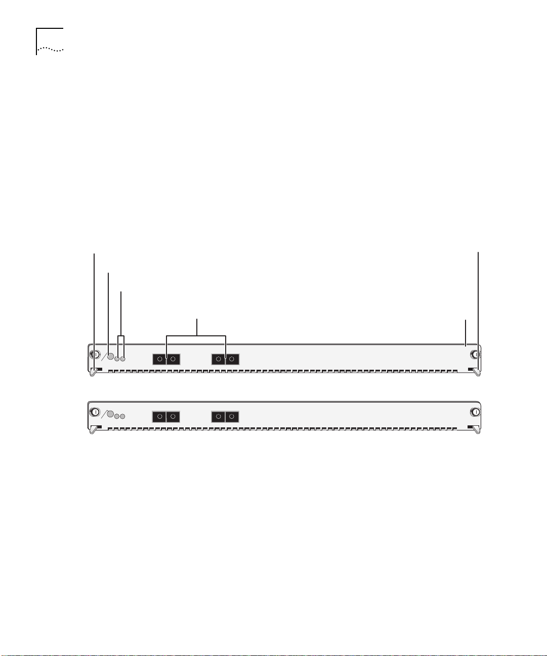
As shown in Figure 1, GEN Interface Modules are available in two
models:
■
1000BASE-LX (order number 3CB9LG2SC). Ports on this module use
a 1300-nanometer, multimode/single-mode, optical transceivers
(colored blue) and SC connectors.
■
1000BASE-SX (order number 3CB9LG2MC). Ports on this module
use an 850-nanometer, multimode, optical transceivers (colored
black) and SC connectors.
Ejector handle
Module Status LED
Port Status LEDs
MOD STAT
1
2
MOD STAT
1
2
Figure 1
Front Panels of the GEN Interface Modules
Ejector handle
Fiber-optic ports
(SC connectors)
Model number
1000BASE-LX
RX
TX
1
RX
TX
2
3CB9LG2SC
1000BASE-SX
RX
TX
1
RX
TX
2
3CB9LG2MC
Each GEN Interface Module has two ports on the front (see Figure 1) as
well as two ports on the rear of the module (not shown in Figure 1)
that connect to the chassis backplane. Because the front ports have a
pass-through function to the rear ports, they share port numbers
1 and 2 with the rear ports.
In the 16-slot chassis, you install modules vertically with the LEDs at the
top. In the 7-slot chassis, you install modules horizontally, as shown in
Figure 1.
Page 3
2-Port 1000BASE-SX and 2-Port 1000BASE-LX Gigabit Ethernet Interface Modules Quick Start Guide
3
Audience Description
Safety Precautions
This guide is intended for
trained technical personnel
only. Do not
attempt to install, remove, or replace a CoreBuilder 9000 GEN Interface
Module if you have not had the proper training from 3Com. For
training information, call 1-800-NET-3COM.
When you handle components in a CoreBuilder 9000 system, be sure
that you follow all safety precautions. To avoid electric shocks, burns, or
equipment damage, read and follow these warnings:
WARNING:
Allow only trained service personnel to install, remove, or
replace a GEN Interface Module.
WARNING:
Hazardous energy exists within the CoreBuilder system. Use
extreme caution when you install, remove, or replace a GEN Interface
Module.
When the system is on, never insert metal objects such as a screwdriver
or a finger with jewelry into open module slots.
When the system is on, do not touch any connections within the
chassis with your hands or fingers. Do not insert metal objects into the
backplane.
WARNING:
To ensure optical safety when installing GEN Interface
Modules, comply with the following precaution:
Although the data communication lasers used in this product meet the
regulatory requirements for casual exposure to the eye, as with any
source of bright light, it is advised that you do not look into the light
source.
Laser Safety Information:
IEC 825 and EN60825, Class 1 Laser
Device. For connection only to Class 1 Laser Devices.
CLASS 1
LASER PRODUCT
FDA Class 1 Laser Device
This product complies with U.S. Department of Health and Human
Services Rules 21 CFR Subchapter J applicable at date of manufacture.
Page 4

4
2-P
1000BASE-SX
ORT
AND
2-P
ORT
1000BASE-LX G
IGABIT ETHERNET INTERFACE MODULES QUICK START GUIDE
ESD Safety Information
Electrostatic discharge (ESD) can damage components of the module.
ESD, which occurs when a GEN Interface Module is improperly
handled, can cause complete or intermittent failures.
CAUTION: To prevent ESD-related damage:
■
Always wear an ESD wrist strap (not provided) when you handle a
GEN Interface Module, ensuring that the strap makes good skin
contact.
■
Keep the GEN Interface Module in its antistatic bag until you are
ready to install it.
Handling Precautions
Unpacking
Instructions
When you handle a GEN Interface Module, follow these precautions:
■
Always handle the module by its front panel only.
■
Do not touch the components, pins, leads, or solder connections.
■
Do not twist or otherwise force the module into the chassis when
you insert it into the module slot guides.
■
Before you push the module into the chassis, make sure that the
module ejector handles are open.
■
To slide the module into the 16-slot chassis, match the upper and
lower module guides; in the 7-slot chassis, match the left and right
module guides.
Use the following procedure when you unpack a GEN Interface
Module:
1
Verify that the GEN Interface Module is the correct product by
matching the order number that is listed on the shipping box label to
the order number that is listed on your sales invoice (3CB9LG2MC or
3CB9LG2SC).
2
Remove the module, in its antistatic bag, from the shipping box.
3
Ensure that the box also contains:
■
CoreBuilder 9000 GEN Switch Fabric and GEN Interface Modules
Release Notes
■
2-Port 1000BASE-SX and 2-Port 1000BASE-LX Gigabit Ethernet
Interface Modules Quick Start Guide for the CoreBuilder 9000
Enterprise Switch
(this guide)
Page 5

2-Port 1000BASE-SX and 2-Port 1000BASE-LX Gigabit Ethernet Interface Modules Quick Start Guide
If the listed contents are not in the shipping box, contact your supplier.
All shipping boxes are reusable. After you remove the contents, replace
the packing materials in the box and store it for future use.
Remove the GEN Interface Module from its antistatic bag and inspect it
4
for physical damage.
5
Installation
Prerequisites
CAUTION:
Handle the module by the front panel only. Do not touch
any components, pins, leads, or solder connections.
If the module appears to be damaged, replace it in its antistatic bag
and shipping box, and contact your supplier.
Before you install a GEN Interface Module, make sure that the
CoreBuilder 9000 chassis is properly installed in a rack, on a table, or
on a shelf, according to the instructions in the
Enterprise Switch Getting Started Guide
Installation Guide
7-Slot Chassis Quick Installation Guide
or
and the
CoreBuilder 9000
16-Slot Chassis Quick
.
You need a flat-blade screwdriver to complete the module installation.
Page 6

6
2-P
1000BASE-SX
ORT
AND
2-P
ORT
1000BASE-LX G
IGABIT ETHERNET INTERFACE MODULES QUICK START GUIDE
Order of Installation
Activities
3Com recommends that you install CoreBuilder 9000 modules in the
following order:
1
Management Modules
One Enterprise Management Engine (EME) is required (order number
3CB9EME). A second EME or an Enterprise Management Controller
(EMC) is optional (order number 3CB9EMC). By installing the
management modules first, you can complete the required system-level
setup procedures before you add other modules to the chassis. For
more information, see the following documents:
■
Enterprise Management Engine User Guide
■
Enterprise Management Engine Quick Start Guide
■
Enterprise Management Controller Quick Start Guide
2
Switch Fabric Modules
Because you manage a GEN Interface Module through the primary GEN
Switch Fabric Module, you must install one GEN Switch Fabric Module
first. In the 16-slot chassis, a second GEN Switch Fabric Module is
optional. See the
Guide
for more information.
3
Interface Modules
Gigabit Ethernet Switch Fabric Module Quick Start
Install all interface modules, such as the 2-port 1000BASE-SX GEN
Interface Module, the 2-port 1000BASE-LX GEN Interface Module, or
the 36-port 10/100BASE-TX Fast Ethernet RJ-45 Layer 2 Switching
Module, last. You can install interface modules in any order, but see
your module documentation for chassis slot restrictions and
recommendations. For restrictions and recommendations for the GEN
Interface Modules, see “Module Placement in the Chassis” next in this
guide.
Page 7

2-Port 1000BASE-SX and 2-Port 1000BASE-LX Gigabit Ethernet Interface Modules Quick Start Guide
7
Module Placement in
the Chassis
Note the following chassis slot restrictions and recommendations when
you choose a chassis slot for a GEN Interface Module.
In the CoreBuilder 9000 7-slot chassis:
■ Do not install the module in slot 7. This slot is reserved for a GEN
Switch Fabric Module.
■ Install the module in slot 1, 2, 3, 4, 5, or 6.
In a CoreBuilder 9000 16-slot chassis:
■ Do not install the module in slot 8 or 9. These slots are reserved for
GEN Switch Fabric Modules.
■ To optimize backplane performance, install the module in slot 1, 2,
3, 4, 5, 6, 7, 10, 11, or 12.
■ 3Com recommends that you do not install the module in slot 13,
14, 15, or 16, because these slots only have one connection to the
backplane and the GEN Switch Fabric Modules (see Table 2). If you
install a GEN Interface Module into one of these slots, you can only
use one of the module’s front panel ports. The GEN Switch Fabric
Module automatically disables the second port.
Table 1 and Table 2 list the relationship between the 24 Gbps Gigabit
Ethernet (GEN) Switch Fabric Module (3CB9FG24) and the interface
module slots in the 7-slot chassis and the 16-slot chassis, respectively.
Use the information to help select a slot for your module, as well as for
administration purposes after you have completed the installation.
Page 8

8
2-P
1000BASE-SX
ORT
AND
2-P
ORT
1000BASE-LX G
IGABIT ETHERNET INTERFACE MODULES QUICK START GUIDE
Table 1
Mapping the GEN SFM*
Number of SFM
Chassis Slot
Number
Backplane Ports
Allocated to Slot
1 4; only 2 are accessed
by this module
2 4; only 2 are accessed
by this module
3 4; only 2 are accessed
by this module
4 4; only 2 are accessed
by this module
5 4; only 2 are accessed
by this module
6 4; only 2 are accessed
by this module
and the 2-port GEN Interface Module to the 7-slot Chassis
2-port GEN
Interface Module
Port Numbers
1
2
1
2
1
2
1
2
1
2
1
2
SFM Backplane Port
Numbers Assigned
to Chassis Slot
1
2
5
6
9
10
13
14
17
18
21
22
SFM LED Numbers
Assigned to Backplane
Port Numbers
1
2
3
4
5
6
7
8
9
10
11
12
7 Reserved for an SFM Not applicable Not applicable Not applicable
*
SFM = Switch Fabric Module
Page 9

2-Port 1000BASE-SX and 2-Port 1000BASE-LX Gigabit Ethernet Interface Modules Quick Start Guide
9
Table 2
Mapping the GEN SFM*
Number of SFM
Chassis Slot
Number
Backplane Ports
Allocated to Slot
1 2 1
2 2 1
3 2 1
4 2 1
5 2 1
6 2 1
7 2 1
and the 2-port GEN Interface Module to the 16-slot Chassis
2-port GEN
Interface Module
Port Numbers
2
2
2
2
2
2
2
SFM Backplane Port
Numbers Assigned
to Chassis Slot
1
2
3
4
5
6
7
8
9
10
11
12
13
14
SFM LED Numbers
Assigned to Backplane
Port Numbers
1
2
3
4
5
6
7
8
9
10
11
12
13
14
8 Reserved for an SFM Not applicable Not applicable Not applicable
9 Reserved for an SFM Not applicable Not applicable Not applicable
10 2 1
2
11 2 1
2
12 2 1
2
15
16
17
18
19
20
15
16
17
18
19
20
13 1 1 21 21
14 1 1 22 22
15 1 1 23 23
16 1 1 24 24
*
SFM = Switch Fabric Module
Page 10

10
2-P
ORT
1000BASE-SX
AND
2-P
ORT
1000BASE-LX G
IGABIT ETHERNET INTERFACE MODULES QUICK START GUIDE
Installing the GEN
Interface Module
Follow this procedure to install a GEN Interface Module:
1
Before you start the installation process, read “Safety Precautions” and
“Handling Precautions” earlier in this guide.
2
Select a chassis slot for your module, following the restrictions and
recommendations in “Module Placement in the Chassis” earlier in this
guide.
3
To expose the selected chassis slot, remove the blank faceplate that
covers the slot.
Save this faceplate, because you may need to cover an empty slot in
the future. Empty slots must be covered to ensure proper air flow and
cooling in the chassis.
4
Open the module ejector handles.
5
Begin to insert the module:
■
In the 7-slot chassis, hold the module horizontally with the LEDs on
the left and insert the module using the guides on the left and the
right of the slot. See Figure 2.
■
In the 16-slot chassis, hold the module vertically with the LEDs at
the top and insert the module using the guides on the top and the
bottom of the slot. See Figure 3.
CAUTION: Be careful not to twist or bend the module when you insert
it.
6
Slide the module into the chassis by pushing firmly at the two ends of
the front panel near the ejector handles.
WARNING: Hazardous energy levels exist inside of the chassis. Do not
place hands or objects into the chassis or touch components on an
inserted module.
Page 11

2-Port 1000BASE-SX and 2-Port 1000BASE-LX Gigabit Ethernet Interface Modules Quick Start Guide
11
Figure 2
Installing the GEN Interface Module in the 7-Slot Chassis
GEN Interface Module
CoreBuilder
9000
3CB9FG24
3CB9FG24
3CB9FG24
3CB9LG2SC
7
6
5
4
3
2
1
MOD STAT
MOD STAT
MOD STAT
MOD STAT
R
SEC123456789101112131415161718192021222324
SEC123456789101112131415161718192021222324
SEC123456789101112131415161718192021222324
PRI
PRI
PRI
2
1
9
8
RX
RX
TX
TX
2
1
Spring-loaded
screws
Page 12

12
2-P
ORT
1000BASE-SX
AND
2-P
ORT
1000BASE-LX G
IGABIT ETHERNET INTERFACE MODULES QUICK START GUIDE
Figure 3
Spring-loaded
Interface
Module
Spring-loaded
Installing the GEN Interface Module in the 16-Slot Chassis
screw
R
1 2 3 4 5 6 7 8 12 13 169 10 11 14 15
MOD STAT
1
2
TX
1
RX
TX
2
RX
MOD STAT
MOD STAT
MOD STAT
MOD STAT
MOD STAT
MOD STAT
SEC
SEC
SEC
SEC
SEC
SEC
PRI
PRI
PRI
PRI
PRI
PRI
1
2
1
2
1
2
1
2
1
2
1
2
3
4
3
4
3
4
3
4
3
4
3
4
5
6
5
6
5
6
5
6
5
6
5
6
7
8
7
8
7
8
7
8
7
8
7
8
9
10
9
10
9
10
9
10
9
10
9
10
11
12
11
12
11
12
11
12
11
12
11
12
13
14
13
14
13
14
13
14
13
14
13
14
15
16
15
16
15
16
15
16
15
16
15
16
17
18
17
18
17
18
17
18
17
18
17
18
19
20
19
20
19
20
19
20
19
20
19
20
21
22
21
22
21
22
21
22
21
22
21
22
23
24
23
24
23
24
23
24
23
24
23
24
CoreBuilder
GEN
3CB9FG24
3CB9FG24
3CB9FG24
3CB9FG24
3CB9FG24
3CB9LG2MC
3CB9FG24
screw
9000
Page 13

2-Port 1000BASE-SX and 2-Port 1000BASE-LX Gigabit Ethernet Interface Modules Quick Start Guide
To engage the module connectors and the chassis backplane
7
connectors, apply forward pressure to the module front panel.
You feel a slight resistance as the connectors engage.
13
CAUTION:
If the resistance is too great, the module connectors and
the backplane connectors may not be aligned. Forcing the module into
place can damage the module connectors and backplane connectors. If
necessary, remove and reinsert the module, ensuring that the
connectors are properly aligned. Do not tighten the spring-loaded
screws to seat the module.
If modules are already installed to the left of this module in a 16-slot
chassis or installed beneath this module in a 7-slot chassis, you may
need to apply sideways or downward pressure on that adjacent module
to have your module line up correctly in its slot. Applying this pressure
compresses the thin strip of rubber-like material (which exists for
electromagnetic interference purposes) at the edge of the front panel
of the adjacent module.
Ensure that the module remains fully seated in the backplane
8
connectors while you close the ejector handles.
Use one hand to hold the module in place, and use your other hand to
close one ejector handle at a time until the handles are parallel with
the front panel.
To secure the module front panel to the chassis, tighten the
9
spring-loaded screws to a torque specification of 3–5 inch-pounds.
CAUTION:
To ensure adequate cooling air flow and continued product
safety agency compliance, install blank faceplates over all empty slots.
Page 14

14
2-P
ORT
1000BASE-SX
AND
2-P
ORT
1000BASE-LX G
IGABIT ETHERNET INTERFACE MODULES QUICK START GUIDE
Verifying Module
Operation
The GEN Interface Modules each have one Module Status LED and two
Port Status LEDs. Watch the LEDs during system power-on to verify
proper module operation. During the power-on diagnostic test, both
the Module Status and Port Status LEDs flash for approximately 1
second, and then reflect the active status of the module as described in
Table 3.
.
Table 3
LED State and Color Description
Module Status
Port Status
Module and Port Status LED Indicators
Green Power is on (normal operation).
Off No power.
Green Port is enabled and link is up.
■
Flashing Green
Port is receiving or transmitting
packets.
■
Port is cabled but the switch fabric
module is down or unavailable.
Off Link is disabled or port is not cabled.
Page 15

2-Port 1000BASE-SX and 2-Port 1000BASE-LX Gigabit Ethernet Interface Modules Quick Start Guide
15
Managing the
Module
You configure and manage the front panel ports on the GEN Interface
Module using the Administration Console, which is a command line
interface that you access from a terminal that is connected through the
Enterprise Management Engine (EME).
At the command prompt, you do not connect directly to a GEN
Interface Module; you manage GEN Interface Modules by connecting to
the primary GEN Switch Fabric Module backplane ports that correspond
to where you have installed the GEN Interface Module in the chassis. To
learn how GEN Switch Fabric Module backplane ports are assigned to
chassis slots, see Table 1 and Table 2 earlier in this guide.
To manage GEN Interface Module ports from the Administration
Console:
Log in to the EME.
1
For information about logging in to the EME, see the
Enterprise Management Engine User Guide.
At the prompt, enter:
2
connect <slot>.1
CoreBuilder 9000
Where <slot> is the slot number of the module that you want to
manage, and the number after the decimal point is a subslot number
(the subslot number is always 1).
Because you manage the GEN Interface Modules through the GEN
Switch Fabric Module, you always connect to slot 7 in the
CoreBuilder 9000 7-slot chassis and to slot 8 or slot 9 in the
CoreBuilder 9000 16-slot chassis.
This command connects you to the primary GEN Switch Fabric Module,
and the Administration Console displays the top-level menu prompt.
To manage a GEN Interface Module port, enter commands for the
3
corresponding backplane port on the primary GEN Switch Fabric
Module.
For information about module commands, see the
Guide
.
Command Reference
Page 16

16
2-P
ORT
1000BASE-SX
AND
2-P
ORT
1000BASE-LX G
IGABIT ETHERNET INTERFACE MODULES QUICK START GUIDE
Specifications
The following tables list specifications for the GEN Interface Modules:
1000BASE-SX (3CB9LG2MC) Module Cabling Requirements
Fiber Type
62.5/125 microns MMF 160 Up to 220 m (722 ft)
62.5/125 microns MMF 200 Up to 275 m (902 ft)
50/125 microns MMF 400 Up to 500 m (1,640 ft)
50/125 microns MMF 500 Up to 550 m (1,804 ft)
10/125 microns SMF Not applicable Not supported
Modal Bandwidth
(MHz•km)
Segment Length
1000BASE-LX (3CB9LG2SC) Module Cabling Requirements
Modal Bandwidth
Fiber Type
(MHz•km) Segment Length
62.5/125 microns MMF 500 Up to 550 m (1,804 ft)
50/125 microns MMF 400 Up to 550 m (1,804 ft)
50/125 microns MMF 500 Up to 550 m (1,804 ft)
10/125 microns SMF Not applicable Up to 5 km (16,404 ft)
Due to the dual media (single-mode and multimode) support of the
1000BASE-LX module, an offset-launch mode-conditioning patch cord
assembly is required to meet the specifications for multimode (MMF)
operation. This patch cord is not required for single mode (SMF)
operation. Patch cords come in various lengths and can be ordered
from Siecor Operations (800-743-2675, fax: 828-327-5973). The
following table lists the part number information:
Patch Cord Cable
Assembly Part Number
Description
39575802KMCXXXM* Mode-conditioning patch cord for 62.5 micron cables
39575802CMCXXXM* Mode-conditioning patch cord for 50 micron cables
* XXX = the length of the cable in meters.
Page 17

2-Port 1000BASE-SX and 2-Port 1000BASE-LX Gigabit Ethernet Interface Modules Quick Start Guide
Environmental Requirements
Operating temperature 0 to 50 °C (32 to 122 °F)
Operating humidity 10% to 90% relative humidity, noncondensing
Storage temperature –30 to 70 °C (–22 to 158 °F)
Storage humidity 10% to 95% relative humidity, noncondensing
Physical Specifications
Module Dimensions Weight
1000BASE-SX
(3CB9LG2MC)
1000BASE-LX
(3CB9LG2SC)
2.54 cm x 38.81 cm x 33.50 cm
1 in. x 15.28 in. x 13.19 in.
2.54 cm x 38.81 cm x 33.50 cm
1 in. x 15.28 in. x 13.19 in.
1.81 kg
4.85 lb
1.81 kg
4.85 lb
Power Specifications
Voltage Minimum Maximum Current
+5 V 4.75 V 5.25 V 1 A
+3.3 V 3.14 V 3.47 V 4.54 A
+12 V 11.4 V 12.6 V 0.125 A
17
Regulatory Compliance
Safety
■
CSA 22.2 No. 950
■
EN60950
■
IEC950
■
UL1950
Emissions
■
FCC 47 CFR Part 15 Class A
■
ICES003 Class A
■
VCCI Class 1
■
EN55022 Class A
■
EN50082-1
■
AS3548
■
CISPR 22 Class A
Page 18

18
2-P
ORT
1000BASE-SX
AND
2-P
ORT
1000BASE-LX G
IGABIT ETHERNET INTERFACE MODULES QUICK START GUIDE
Related
CoreBuilder 9000
Documents
For detailed information about using and managing GEN Interface
Modules, see the following documents:
■
CoreBuilder 9000 Implementation Guide
■
Command Reference Guide
■
CoreBuilder 9000 Enterprise Management Engine User Guide
To obtain the software code installation procedure as well as known
problem information for GEN Interface Modules, see the
CoreBuilder 9000 GEN Switch Fabric and GEN Interface Modules
Release Notes
.
For information about installing and powering on the system, see the
following documents:
■
CoreBuilder 9000 Enterprise Switch Getting Started Guide
■
16-Slot Chassis Quick Installation Guide for the CoreBuilder 9000
Enterprise Switch
■
7-Slot Chassis Quick Installation Guide for the CoreBuilder 9000
Enterprise Switch
■
16-Slot Chassis Power Supply Installation Guide for the
CoreBuilder 9000 Enterprise Switch
■
7-Slot Chassis Power Supply Installation Guide for the
CoreBuilder 9000 Enterprise Switch
You can view and print these and other CoreBuilder 9000 documents
from the:
■
3Com Web site —
■
CoreBuilder 9000 Documentation CD-ROM
http://support.3com.com/nav/switches.htm
The CoreBuilder 9000 Documentation CD-ROM is included when
you order a CoreBuilder 9000 Starter Kit (order number 3CB9PG1 or
3CB9PG2). You can also order the CD-ROM separately (order
number 3CB9DB).
Page 19

Page 20

Page 21

3Com Corporation L
The duration of the warranty for the CoreBuilder™ 9000 1000BASE-SX (3CB9LG2MC) and 1000BASE-LX (3CB9LG2SC) Gigabit Ethernet
Interface Modules is 1 year.
IMITED WARRANTY
ARDWARE
H
OFTWARE
S
EAR
Y
2000 W
ARRANTY
3Com warrants its hardware products to be free from defects in workmanship and materials, under normal
use and service, for the following lengths of time from the date of purchase from 3Com or its authorized
reseller:
Network Interface Cards Lifetime
Other hardware products
*unless otherwise specified above
Spare parts and spares kits 90 days
If a product does not operate as warranted above during the applicable warranty period, 3Com shall, at its
option and expense, repair the defective product or part, deliver to Customer an equivalent product or part
to replace the defective item, or refund to Customer the purchase price paid for the defective product. All
products that are replaced will become the property of 3Com. Replacement products may be new or
reconditioned. Any replaced or repaired product or part has a ninety (90) day warranty or the remainder of
the initial warranty period, whichever is longer.
3Com warrants that the software programs licensed from it will perform in substantial conformance to the
program specifications therefor for a period of ninety (90) days from the date of purchase from 3Com or its
authorized reseller. 3Com warrants the media containing software against failure during the warranty
period. No updates are provided. 3Com’s sole obligation with respect to this express warranty shall be (at
3Com’s discretion) to refund the purchase price paid by Customer for any defective software products, or
to replace any defective media with software which substantially conforms to applicable 3Com published
specifications. Customer assumes responsibility for the selection of the appropriate applications program
and associated reference materials. 3Com makes no warranty or representation that its software products
will meet Customer’s requirements or work in combination with any hardware or applications software
products provided by third parties, that the operation of the software products will be uninterrupted or
error free, or that all defects in the software products will be corrected. For any third party products listed
in the 3Com software product documentation or specifications as being compatible, 3Com will make
reasonable efforts to provide compatibility, except where the non-compatibility is caused by a “bug” or
defect in the third party's product.
In addition to the Hardware Products Warranty and Software Products Warranty identified above, 3Com
warrants that all Heritage 3Com products sold or licensed to Customer on and after January 1, 1998 that
are date sensitive will continue performing properly with regard to such date data on and after January 1,
2000, provided that all other products used by Customer in connection or combination with the 3Com
products, including hardware, software, and firmware, accurately exchange date data with the 3Com
products, with the exception of those products identified at 3Com’s Web site,
http://www.3com.com/products/yr2000.html, as not meeting this standard. A product is considered a
“Heritage 3Com product” if it is a member of a product family which was manufactured by 3Com prior to
its merger with US Robotics Corporation. This Year 2000 limited warranty does not apply to Heritage US
Robotics Corporation products. If it appears that any such product does not perform properly with regard
to such date data on and after January 1, 2000, and Customer notifies 3Com before the later of April 1,
2000, or ninety (90) days after purchase of the product from 3Com or its authorized reseller, 3Com shall,
at its option and expense, provide a software update which would effect the proper performance of such
product, repair such product, deliver to Customer an equivalent product to replace such product, or if none
of the foregoing is feasible, refund to Customer the purchase price paid for such product.
Any software update or replaced or repaired product will carry a Year 2000 Warranty for ninety (90) days
or until April 1, 2000, whichever is later.
1 year*
Page 22

O
BTAINING WARRANTY
S
ERVICE
W
ARRANTIES EXCLUSIVE
Customer must contact 3Com’s Corporate Service Center or an Authorized 3Com Service Center within the
applicable warranty period to obtain warranty service authorization. Dated proof of purchase may be
required. Products returned to 3Com’s Corporate Service Center must be pre-authorized by 3Com with a
Return Material Authorization (RMA) number marked on the outside of the package, and sent prepaid and
packaged appropriately for safe shipment, and it is recommended that they be insured. The repaired or
replaced item will be shipped to Customer, at 3Com’s expense, not later than thirty (30) days after receipt
of the defective product by 3Com.
Dead- or Defective-on-Arrival. In the event a product completely fails to function or exhibits a defect in
materials or workmanship within the first forty-eight (48) hours of installation but no later than thirty (30)
days after the date of purchase, and this is verified by 3Com, it will be considered dead- or
defective-on-arrival (DOA) and a replacement shall be provided by advance replacement. The replacement
product will normally be shipped not later than three (3) business days after 3Com’s verification of the DOA
product, but may be delayed due to export or import procedures. When an advance replacement is
provided and Customer fails to return the defective product to 3Com within fifteen (15) days after
shipment of the replacement, 3Com will charge Customer for the replacement product, at list price.
3Com shall not be responsible for any software, firmware, information, or memory data of Customer
contained in, stored on, or integrated with any products returned to 3Com for repair, whether under
warranty or not.
IF A 3COM PRODUCT DOES NOT OPERATE AS WARRANTED ABOVE, CUSTOMER’S SOLE REMEDY FOR
BREACH OF THAT WARRANTY SHALL BE REPAIR, REPLACEMENT, OR REFUND OF THE PURCHASE PRICE
PAID, AT 3COM’S OPTION. TO THE FULL EXTENT ALLOWED BY LAW, THE FOREGOING WARRANTIES AND
REMEDIES ARE EXCLUSIVE AND ARE IN LIEU OF ALL OTHER WARRANTIES, TERMS, OR CONDITIONS,
EXPRESS OR IMPLIED, EITHER IN FACT OR BY OPERATION OF LAW, STATUTORY OR OTHERWISE,
INCLUDING WARRANTIES, TERMS, OR CONDITIONS OF MERCHANTABILITY, FITNESS FOR A PARTICULAR
PURPOSE, AND SATISFACTORY QUALITY. 3COM NEITHER ASSUMES NOR AUTHORIZES ANY OTHER
PERSON TO ASSUME FOR IT ANY OTHER LIABILITY IN CONNECTION WITH THE SALE, INSTALLATION,
MAINTENANCE OR USE OF ITS PRODUCTS.
3COM SHALL NOT BE LIABLE UNDER THIS WARRANTY IF ITS TESTING AND EXAMINATION DISCLOSE THAT
THE ALLEGED DEFECT IN THE PRODUCT DOES NOT EXIST OR WAS CAUSED BY CUSTOMER’S OR ANY
THIRD PERSON'S MISUSE, NEGLECT, IMPROPER INSTALLATION OR TESTING, UNAUTHORIZED ATTEMPTS TO
REPAIR OR MODIFY, OR ANY OTHER CAUSE BEYOND THE RANGE OF THE INTENDED USE, OR BY
ACCIDENT, FIRE, LIGHTNING, OR OTHER HAZARD.
L
IMITATION OF LIABILITY
D
ISCLAIMER
G
OVERNING LAW
TO THE FULL EXTENT ALLOWED BY LAW, 3COM ALSO EXCLUDES FOR ITSELF AND ITS SUPPLIERS ANY
LIABILITY, WHETHER BASED IN CONTRACT OR TORT (INCLUDING NEGLIGENCE), FOR INCIDENTAL,
CONSEQUENTIAL, INDIRECT, SPECIAL, OR PUNITIVE DAMAGES OF ANY KIND, OR FOR LOSS OF REVENUE
OR PROFITS, LOSS OF BUSINESS, LOSS OF INFORMATION OR DATA, OR OTHER FINANCIAL LOSS ARISING
OUT OF OR IN CONNECTION WITH THE SALE, INSTALLATION, MAINTENANCE, USE, PERFORMANCE,
FAILURE, OR INTERRUPTION OF ITS PRODUCTS, EVEN IF 3COM OR ITS AUTHORIZED RESELLER HAS BEEN
ADVISED OF THE POSSIBILITY OF SUCH DAMAGES, AND LIMITS ITS LIABILITY TO REPAIR, REPLACEMENT,
OR REFUND OF THE PURCHASE PRICE PAID, AT 3COM’S OPTION. THIS DISCLAIMER OF LIABILITY FOR
DAMAGES WILL NOT BE AFFECTED IF ANY REMEDY PROVIDED HEREIN SHALL FAIL OF ITS ESSENTIAL
PURPOSE.
Some countries, states, or provinces do not allow the exclusion or limitation of implied warranties or the
limitation of incidental or consequential damages for certain products supplied to consumers or the
limitation of liability for personal injury, so the above limitations and exclusions may be limited in their
application to you. When the implied warranties are not allowed to be excluded in their entirety, they will
be limited to the duration of the applicable written warranty. This warranty gives you specific legal rights
which may vary depending on local law.
This Limited Warranty shall be governed by the laws of the State of California, U.S.A. excluding its conflicts
of laws principles and excluding the United Nations Convention on Contracts for the International Sale of
Goods.
Page 23

E
MISSIONS COMPLIANCE
S
TATEMENTS FOR CLASS
RODUCTS
P
Federal Communications
Commission Notice
Canadian Emissions Requirements This Class A digital apparatus meets all requirements of the Canadian Interference-Causing Equipment
VCCI Class A Compliance
EMC D
IRECTIVE STATEMENT
EMC Directive Compliance This equipment was tested and found to conform to the Council Directive 89/336/EEC for electromagnetic
A
This equipment has been tested and found to comply with the limits for a Class A digital device, pursuant to
part 15 of the FCC rules. These limits are designed to provide reasonable protection against harmful
interference when the equipment is operated in a commercial environment. This equipment generates, uses
and can radiate radio frequency energy and, if not installed and used in accordance with the instruction
manual, may cause harmful interference to radio communications. Operation of this equipment in a residential
area is likely to cause harmful interference in which case the user will be required to correct the interference at
his own expense.
Regulations.
Cet appareil numérique de la classe A respecte toutes les exigences du Règlement sur le matériel brouilleur du
Canada.
This is a Class A product based on the standard of the Voluntary Control Council for Interference by
Information Technology Equipment (VCCI). If this equipment is used in a domestic environment, radio
disturbance may arise. When such trouble occurs, the user may be required to take corrective actions.
compatibility. Conformity with this Directive is based upon compliance with the following harmonized
standards:
EN 55022 Limits and Methods of Measurement of Radio Interference
EN 50082-1 Electromagnetic Compatibility Generic Immunity Standard:
Residential, Commercial, and Light Industry
: This is a Class A product. In a domestic environment, this product may cause radio interference, in
Warning
which case you may be required to take adequate measures.
LOW V
OLTAGE DIRECTIVE
S
TATEMENT
Low Voltage Directive Compliance This equipment was tested and found to conform to the Council Directive 72/23/EEC for safety of electrical
equipment. Conformity with this Directive is based upon compliance with the following harmonized
standard:
EN 60950 Safety of Information Technology Equipment
Page 24

G
ENERAL APPROVAL
S
TATEMENT FOR
UK General Approval Statement This equipment is manufactured to the international Safety Standard EN60950 and is approved in the UK
UK
under the General Approval Number NS/G/12345/J/100003 for indirect connection to the public
telecommunication network.
A
USTRALIAN
RAMEWORKS STATEMENT
F
EMC
Australian EMC Frameworks
Compliance
3Com Corporation
5400 Bayfront Plaza
Santa Clara, California
95052-8145
This product conforms to the EMC Frameworks and meets the Class A limits of AS3548.
Copyright © 1998, 3Com Corporation. All rights reserved. No part of this documentation may be reproduced
in any form or by any means or used to make any derivative work (such as translation, transformation, or
adaptation) without written permission from 3Com Corporation.
3Com Corporation reserves the right to revise this documentation and to make changes in content from time
to time without obligation on the part of 3Com Corporation to provide notification of such revision or change.
3Com Corporation provides this documentation without warranty, term, or condition of any kind, either
implied or expressed, including, but not limited to, the implied warranties, terms, or conditions of
merchantability, satisfactory quality, and fitness for a particular purpose. 3Com may make improvements or
changes in the product(s) and/or the program(s) described in this documentation at any time.
Unless otherwise indicated, 3Com registered trademarks are registered in the United States and may or may not
be registered in other countries.
3Com and the 3Com logo are registered trademarks of 3Com Corporation. CoreBuilder is a trademark of
3Com Corporation.
Adobe, Acrobat, and Acrobat Reader are registered trademarks of Adobe Systems Incorporated.
All other company and product names may be trademarks of the respective companies with which they are
associated.
3Com Corporation
, 5400 Bayfront Plaza, Santa Clara, CA 95052-8145 (408) 326-5000
Part No. 10011897
Published December 1998
 Loading...