


50M56U-843
Universal Single Stage
HSI Integrated Furnace Control Kit
INSTALLATION INSTRUCTIONS
INSTALLER MUST READ
PAGE 3 CONTAINS WIRING HARNESS AND BLOWER CONNECTION INSTRUCTIONS FOR ALL APPLICATIONS AND IMPORTANT OEM REPLACEMENT INSTRUCTION FOR:
●TRANE / AMERICAN STANDARD
●RHEEM / RUUD
●BRYANT / CARRIER / DAY & NIGHT / PAYNE
FAILURETO READ AND FOLLOW ALL INSTRUCTIONS CAREFULLY BEFORE INSTALLING OR OPERATING THIS CONTROL COULD CAUSE PERSONAL INJURY AND/OR PROPERTY DAMAGE.
DESCRIPTION
The 50M56U-843 kit is a Universal Single Stage HSI Integrated Furnace Control that employs a microprocessor to continually monitor, analyze, and control the proper operation of the gas burner, inducer, and fan.
The kit contains: |
|
||
• 50M56-843 Ignition Control Module |
21D64-2 |
||
• |
21D64-2 Ignitor Kit |
||
|
|||
• |
Set of Interconnect Harnesses |
50M56-843 |
|
Installation should be done by a qualified heating and air conditioning contractor or licensed electrician.
If in doubt about whether your wiring is millivolt, line, or low voltage, have it inspected by a qualified heating and air conditioning contractor or licensed electrician.
Do not exceed the specification ratings.
All wiring must conform to local and national electrical codes and ordinances.
This control is a precision instrument, and should be handled carefully. Rough handling or distorting components could cause the control to malfunction.
Following installation or replacement, follow manufacturer’s recommended installation/service instructions to ensure proper operation.
! CAUTION
Do not short out terminals on gas valve or primary control. Short or incorrect wiring may damage the thermostat.
CONTENTS |
|
Description................................................................... |
1 |
Precautions.................................................................. |
1 |
Specifications............................................................... |
2 |
Installation.................................................................... |
2 |
Mounting & Wiring |
|
Operation...................................................................... |
6 |
Troubleshooting............................................................ |
8 |
PRECAUTIONS
! WARNING 

Failure to comply with the following warnings could result in personal injury or property damage.
FIRE HAZARD
•Do not exceed the specified voltage.
•Replace existing control with exact model and dash number.
•Protect the control from direct contact with water
(dripping, spraying, rain, etc.).
•If the control has been in direct contact with water, replace the control.
•Label all wires before disconnection when servicing controls. Wiring errors can cause improper and dangerous operation.
•Route and secure wiring away from flame.
SHOCK HAZARD
•Disconnect electric power before servicing.
•Ensure proper earth grounding of appliance.
•Ensure proper connection of line neutral and line hot wires.
EXPLOSION HAZARD
•Shut off main gas to appliance until installation is complete.
www.white-rodgers.com |
PART NO. 37-7042C |
Replaces 37-7042B |
|
www.emersonclimate.com |
1103 |
SPECIFICATIONS
ELECTRICAL RATINGS [@ 77°F (25°C)]: |
TIMING SPECIFICATIONS |
Input Voltage: 25 VAC 50/60 Hz |
(All times are in seconds, unless noted otherwise |
|
Max. Input Current @ 25 VAC: 0.45 amp Relay Load Ratings:
Valve Relay: 1.5 amp @ 25 VAC 50/60 Hz 0.6 pf Ignitor Relay:6.0 amp @ 120 VAC 50/60 Hz (resistive) Inducer Relay: 2.2 FLA–3.5 LRA @ 120 VAC Circulator Relay: 14.5 FLA–25.0 LRA @ 120 VAC
Flame Current Requirements:
Minimum current to insure flame detection: 1 µa DC* Maximum current for non-detection: 0.1 µa DC* Maximum allowable leakage resistance: 100 M ohms
*Measured with a DC microammeter in the flame probe lead
OPERATING TEMPERATURE RANGE:
-40° to 176°F (-40° to 80°C)
HUMIDITY RANGE:
MOUNTING:
Surface mount multipoise |
|
Timing Specs: (@ 60 Hz) |
|
|
maximum |
Flame Establishing Time: |
0.8 sec |
Flame Failure Response Time: |
2.0 sec |
Gases Approved: Natural, Manufactured, Mixed, Liquified Petroleum, and LP Gas Air Mixtures are all approved for use.
INSTALLATION
|
50M56U-843 |
|
|
|
|
Pre-Purge |
30 |
|
|
|
|
Initial Ignitor Warm-Up |
17 |
|
(1st 64 attempts) |
||
|
||
|
|
|
Maximum Ignitor Warm-Up |
19 |
|
|
|
|
Ignition Activation Period |
2 |
|
|
|
|
Trial for Ignition Period |
4 |
|
|
|
|
Retries |
2 |
|
|
|
|
Recycles |
3 |
|
|
|
|
Valve Sequence Period |
12 |
|
|
|
|
Interpurge |
60 |
|
|
|
|
Post-Purge |
25 |
|
|
|
|
Lockout Time |
275 |
|
|
|
|
Heat Delay-To-Fan-On |
30 |
|
|
|
|
Heat Delay-To-Fan-Off |
100/150* |
|
|
|
|
Cool Delay-To-Fan-On |
6 |
|
|
|
|
Cool Delay-To-Fan-Off |
45 |
|
|
|
|
Auto Reset |
60 minutes |
|
|
|
*These times will vary depending on option switch position. See OPERATION section for further information.
|
|
MOUNTING AND WIRING |
! WARNING |
|
|
|
All wiring should be installed by a qualified heating and air |
|
|
|
|
|
|
conditioning contractor or licensed electrician, according to |
|
|
local and national electrical codes and ordinances. |
FIRE HAZARD |
|
|
|
The control must be secured to an area that will experience a |
|
• Do not exceed the specified voltage. |
|
|
|
minimum of vibration and remain below the maximum ambient |
|
• Replace existing control with exact model and |
|
|
|
temperature rating of 176°F. The control is approved for |
|
dash number. |
|
|
|
minimum ambient temperatures of -40°F. |
|
• Protect the control from direct contact with water |
|
|
|
|
|
(dripping, spraying, rain, etc.). |
|
When mounting the control, any orientation is acceptable. |
• If the control has been in direct contact with |
|
Choose a location that will not damage, obstruct or place |
water, replace the control. |
|
stress on the control’s terminations, system wiring harness or |
• Label all wires before disconnection when serv- |
|
system components. After finding a suitable location, drill four |
icing controls. Wiring errors can cause improper |
|
(4) 1/8” holes for mounting control.To ensure proper mounting |
and dangerous operation. |
|
hole locations, use the control as a template. When drilling |
• Route and secure wiring away from flame. |
|
the holes, take care so that the transformer, wiring harness or |
SHOCK HAZARD |
|
other system components are not damaged. Four (4) #8 sheet |
|
metal screws are provided to complete the installation. |
|
• Disconnect electric power before servicing. |
|
|
|
|
•Ensure proper earth grounding of appliance. Refer to the wiring diagram and wiring table when connecting
•Ensure proper connection of line neutral and line the 50M56U-843 control to other components of the system.
hot wires. |
UL approved, 105°C rated 18 gauge, stranded, 2/64” thick |
|||
|
|
|
||
EXPLOSION HAZARD |
insulation wire is recommended for all low voltage safety circuit |
|||
• Shut off main gas to appliance until installation |
connections. |
|||
is complete. |
UL approved 105°C rated 16 gauge min., stranded, 4/64” |
|||
|
|
|
||
|
|
|
thick insulation wire is recommended for all line voltage |
|
|
! CAUTION |
|
connections. |
|
|
|
|
||
|
|
|
Afterinstallationorreplacement,followappliancemanufacturer’s |
|
Do not short out terminals on gas valve or primary |
||||
recommended installation or service instructions to ensure |
||||
control. Short or incorrect wiring may damage the |
||||
proper operation. |
||||
thermostat. |
||||
|
||||
|
|
|
|
|
2
INSTALLER MUST READ FOR PROPER
INSTALLATION
•Wiring harnesses and a Universal 21D64-2 ignitor are included in this package. Refer to the enclosed “Cross
Reference and Harness Application Chart” (Part Number
37-7077) for harness selection and ignitor application information. Ignitor installation instructions are in the
UNIVERSAL 21D64-2 Ignitor package included with this kit.
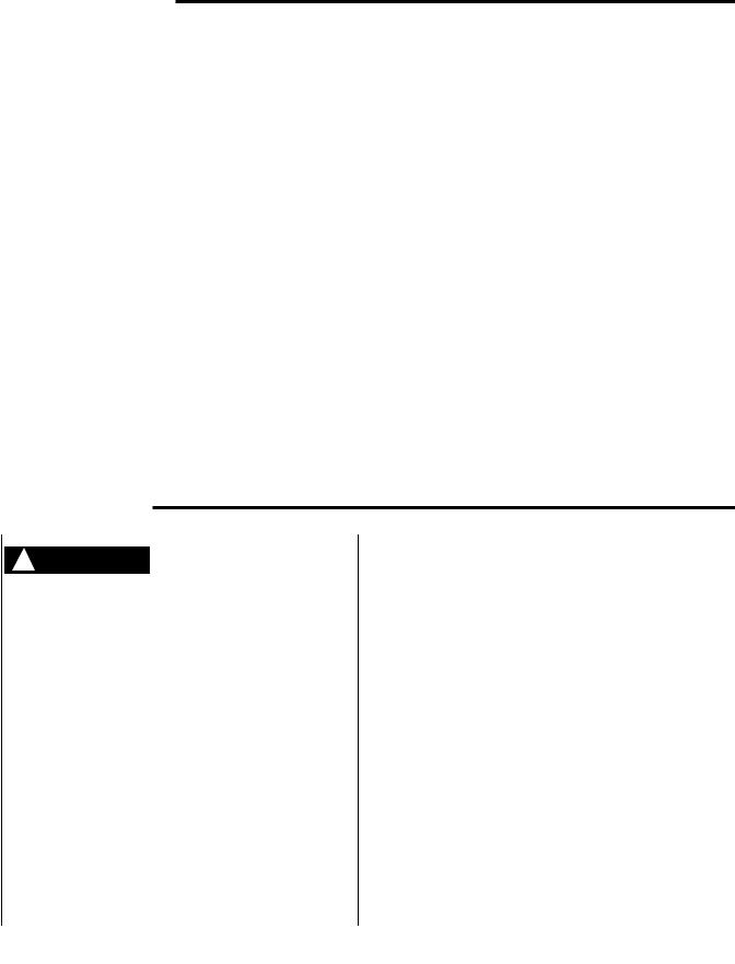
•IMPORTANT: For continuous fan speed operation, one of the unused parked motor taps must be connected to the low heat speed terminal. Failure to do this will result in the blower not energizing in the constant fan mode operation.
Refer to figure 1.
•Installer must read Page (6) “Operation” and follow option switch setting for proper control operation.
•In certain applications it may be necessary to remove the control board from the cover to be mounted in the space allowed. Standoffs supplied in the package must be installed before the control board can be mounted.
•4 Blower lead extensions are included in the kit if extra length is needed to complete installation.
IMPORTANT OEM REPLACEMENT INSTRUCTIONS
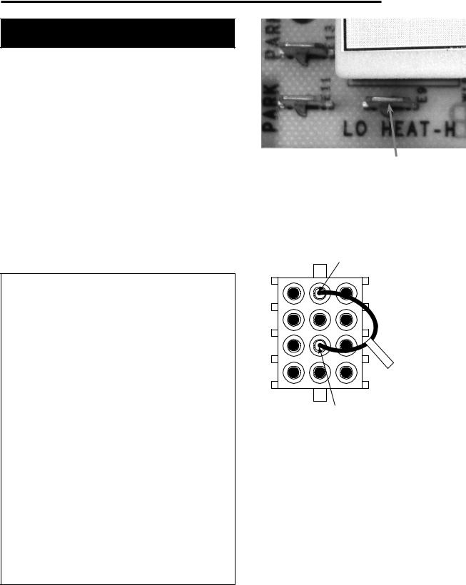
•TRANE and AMERICAN STANDARD
For all TRANE and AMERICAN STANDARD furnaces only: Install jumper 0151 290600 (included in this package) into the back of the furnace 12 pin connector harness from pin 5 to pin 11 as shown in Figure 2.
Make sure jumper snaps into the connector securely.
•RHEEM / RUUD (1994 and earlier models)
If the furnace control being replaced has 2 green lights and NO amber light (furnace date code 3294 or earlier) a Flame Sensor Kit, RHEEM Part Number 62-24044-71
(not available from White-Rodgers) is required. Install the flame sensor and plug the flame sensor lead into pin 7 of the connector on the furnace as detailed in the Rheem Flame Sensor Kit instructions. Plug the furnace connector into harness “B” (included in this package). Plug the other end of harness “B” into the new module. Attach the orange wire from harness “B” (3/16” female spade terminal) to FS on the new module to complete the flame sense circuit.
•BRYANT / CARRIER / DAY & NIGHT / PAYNE
This kit will not replace BRYANT / CARRIER / DAY & NIGHT / PAYNE HK42FZ013 modules or CARRIER / BDP modules using an 11 pin (straight) connector.
Refer to the enclosed “Cross Reference and Harness
Application Chart” (Instruction sheet Part Number 37-
7077) included with this kit for the list of modules it replaces.
INSTALLATION
Figure 1 |
For continuous fan speed |
|
|
|
connect one of the unused |
|
parked terminals here |
Pin 11 (RO In)
Jumper 0151-290600
(for Trane and American  Standard applications only)
290600 J
Pin 5 (RO Out)
Figure 2. 12 Pin Connector (back view) on existing Wire Harness in Furnace
3
 Loading...