


model nsp130
Professional Style
Range Hood
Page
read and save these instructions
for domestic cooking only
warning
TO REDUCE THE RISK OF FIRE, ELECTRIC SHOCK, OR INJURY TO PERSONS, OBSERVE THE FOLLOWING:
1.Use this unit only in the manner intended by the manufacturer. If you have questions, contact the manufacturer at the address or telephone number listed in the warranty.
2.Before servicing or cleaning unit, switch power off at service panel. Lock or tag service panel to prevent power from being switched on accidentally.
3.Installation work and electrical wiring (including switch location) must be done by a qualified person(s) in accordance with all applicable codes and standards, including fire-rated construction.
4.Provide sufficient air for proper combustion and exhausting of gases through the flue (chimney) of fuel burning equipment to prevent backdrafting. Follow the combustion equipment standards such as those published by the National Fire Protection Association (NFPA), the American Society for Heating, Refrigeration and Air Conditioning Engineers (ASHRAE), and local codes.
5.This product may have sharp edges. Be careful to avoid cuts and abrasions during installation and cleaning.
6.When cutting or drilling into wall or ceiling, do not damage electrical wiring and other hidden utilities.
7.Ducted fans must always be vented to the outdoors.
8.Use only metal ductwork.
9.As an alternative, this product may be installed with the ULapproved cord kit designated for the product, following instructions packed with the cord kit.
10.This unit must be grounded.
warning
TO REDUCE THE RISK OF INJURY TO PERSONS IN THE EVENT OF A RANGE TOP GREASE FIRE, OBSERVE THE FOLLOWING:*
1.SMOTHER FLAMES with a close-fitting lid, cookie sheet, or metal tray, then turn off the burner. BE CAREFUL TO
PREVENT BURNS. If the flames do not go out immediately,
EVACUATE AND CALL THE FIRE DEPARTMENT.
2.NEVER PICK UP A FLAMING PAN — You may be burned or spread the fire.
3.DO NOT USE WATER, including wet dishcloths or towels
-violent steam explosion will result.
4.Use an extinguisher ONLY if:
A.You know you have a Class ABC extinguisher and you already know how to operate it.
B.The fire is small and contained in the area where it started.
C.The fire department is being called.
D.You can fight the fire with your back to an exit.
* Based on “Kitchen Fire Safety Tips” published by NFPA.
caution
1.For general ventilating use only. Do not use to exhaust hazardous or explosive materials and vapors.
2.For best capture of cooking impurities, range hood should be mounted so that the bottom of the hood is 18”-24” above the cooking surface.
TO REDUCE THE RISK OF A RANGE TOP GREASE FIRE:
1.Never leave surface units unattended at high settings. Boilovers cause smoking and greasy spillovers that may ignite. Heat oils slowly on low or medium settings.
2.Always turn hood ON when cooking at high heat or when flambeing food (i.e. Crepes Suzette, Cherries Jubilee, Peppercorn Beef Flambe).
3.Clean ventilating fans frequently. Grease should not be allowed to accumulate on fan or filter.
4.Use proper pan size. Always use cookware appropriate for the size of the surface element.
3.Read specification label on product for information and requirements.
Installer: Leave this manual with the homeowner. Homeowner: Cleaning, Maintenance and Operating instructions on page 2.
model nsp130
cleaning & Maintenance
For performance, appearance, and health reasons, clean filter, fan and grease-laden surfaces. Use only a clean cloth and mild detergent solution on stainless and painted surfaces. Clean allmetal filters in the dishwasher.
The motor is permanently lubricated and never needs oiling. If the motor bearings make excessive or unusual noise, replace the motor with the exact service motor. The impeller should also be replaced.
Use 120 V, 50 W, shielded halogen bulbs - MR16 or PAR16 with GU10 base. Purchase bulbs separately.
The grease filters, bottom panel, and blower wheel should be cleaned frequently. Use a warm detergent solution. The grease filters and blower wheel are dishwasher safe.
Note: Some minerals, when in contact with dishwasher soap additives, may cause filters to discolor. This discoloration is not covered by the warranty.
operation
Always turn the hood ON before cooking in order to establish an air flow in the kitchen.After turning off the range, let the hood run for a few minutes to clear the air.
HEAT SENTRY™
The hood is equipped with a Heat Sentry™ thermostat. This safety device will turn on or speed up the blower if it senses excess heat above the cooking surface.
If the blower is not on, or if it is running at low speed, the Heat Senttry™ will override the normal blower control and trun the blower on the high speed. When the temperature level drops to normal levels, the blower will return to its original setting.
Operate the hood as follows:
 Blower Switch
This 3-position switch turns blower ON and OFF and controls blower speed.
Set switch to (1) position to turn blower ON to low speed. Set switch to (2) position to turn blower ON to high speed. Set switch to (0) position to turn blower OFF.
 light switch
This 3-position switch turns lights ON and OFF and controls their intensity.
Set switch to (1) position to turn lights ON to low intensity. Set switch to (2) position to turn lights ON to high intensity. Set switch to (0) position to turn lights OFF.
Page
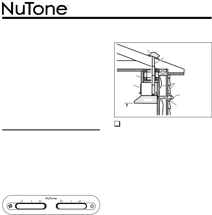
prepare hood location
ROOF CAP |
3¼" X 10" |
|
|
|
(For vertical |
|
discharge) |
SOFFIT |
|
|
HOUSE WIRING |
CABINET |
(Top or Back of hood) |
|
WALL CAP |
HOOD |
|
|
3¼" X 10" DUCT |
18" - 24" ABOVE |
(For horizontal discharge) |
|
|
COOKING SURFACE |
|
1 Determine whether hood will discharge vertically or hori- |
|
zontally. For vertical or horizontal discharge, run ductwork |
|
between the hood location and a roof cap or wall cap. For |
|
best results, use a minimum number of transitions and |
|
elbows. |
|
model nsp130
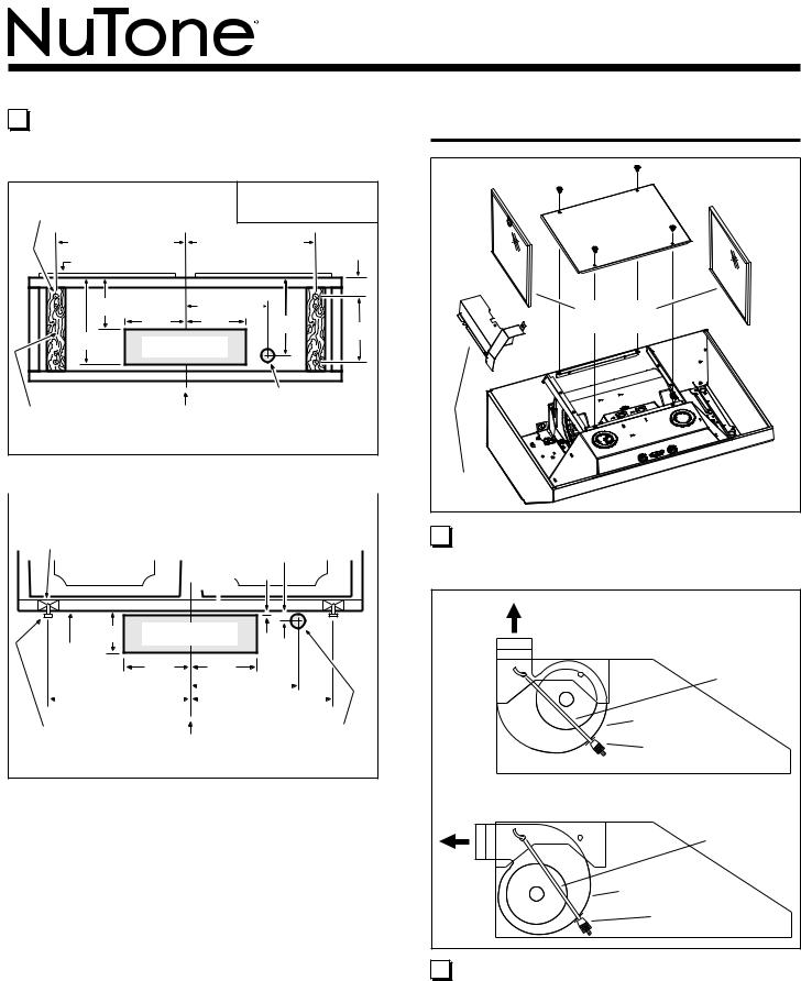
2 |
Use the proper diagram below, for placement of ductwork |
|
and electrical cutout in cabinet or wall. |
|
|
|
|
3¼” X 10” |
|
HOOD MOUNTING SCREWS (4) |
VERTICAL DUCTING |
||||
1315/16" (30" hood) |
1315/16" (30" hood) |
|
|||
1615/16" (36" hood) |
1615/16" (36" hood) |
|
|||
CABINET FRONT |
|
|
|
||
|
CABINET |
71/2" |
11/4" |
||
67/8" |
|
||||
BOTTOM |
|
||||
105/8" |
|
6¼" |
6¼" |
97/8" |
9" |
|
VERTICAL DUCT |
|
|||
|
|
|
|||
|
|
ACCESS HOLE |
|
|
|
WOOD SHIMS |
|
|
|
ELECTRICAL |
|
|
CENTER |
ACCESS HOLE |
|
||
(recessed-bottom |
(in cabinet bottom) |
|
|||
LINE |
|
|
|||
cabinets only) |
|
|
|
|
|
|
|
|
|
|
|
WOOD SHIMS |
|
3¼” X 10” |
(recessed-bottom |
|
horizontAL DUCTING |
cabinets only) |
|
|
CABINET FRONT 3/4" |
||
1/8" |
37/8" |
HORIZONTAL DUCT |
|
ACCESS HOLE |
||
CABINET |
6¼" |
6¼" |
BOTTOM |
||
13 |
15 |
/16" (30" hood) |
|
|
|
|
|
71/2" |
|
|
|
|
||||
|
|
|
|
|
|
|
|
|
||||||||
|
|
|
|
|
1315/16" (30" hood) |
|
|
|||||||||
|
|
|
15 |
|
|
|
|
|
|
|
|
|||||
16 |
/16" (36" hood) |
|
|
|
|
|
||||||||||
|
|
|
|
|
1615/16" (36" hood) |
|||||||||||
HOOD |
|
|
|
|
|
|
||||||||||
|
|
|
|
|
|
|
ELECTRICAL |
|||||||||
MOUNTING |
CENTER |
|||||||||||||||
SCREWS (4) |
ACCESS HOLE |
|||||||||||||||
|
LINE |
|
||||||||||||||
|
|
|
|
|
|
|
|
(in wall) |
||||||||
Page
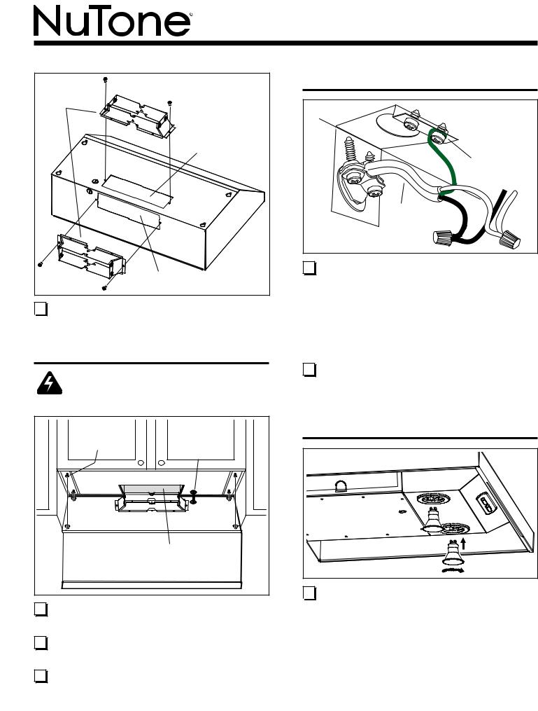
PREPARE THE HOOD
bottom |
cover |
aluminum |
filters |
wiring |
cover |
3 Remove the Aluminum Filters, Bottom Cover, and
Wiring Cover from the hood.
vertical discharge position |
|
|
blower |
|
mounting |
|
rod (2) |
blower |
|
knurled nut (2) |
|
horizontal discharge position |
blower |
|
|
|
mounting |
|
rod (2) |
blower |
|
knurled nut (2) |
|
4 |
Blower is shipped in Vertical Discharge Position. |
To change blower to Horizontal Discharge Position:
Remove Knurled Nuts from Blower Mounting Rods. Disengage mounting rods from blower and rotate blower to horizontal discharge position. Re-engage mounting rods and tighten blower in place with knurled nuts.
model nsp130
damper / |
duct |
connector |
vertical duct |
knockout |
horizontal duct |
knockout |
5 Remove Vertical Duct Knockout or Horizontal Duct  Knockout and attach Damper / Duct Connector with
two (2) screws (supplied).
Install the hood
WARNING
To reduce the risk of electrical shock, switch power off  at service panel. Lock or tag service panel to prevent
power from being switched on accidentally.
mounting |
house |
screws (4) |
power |
|
cable |
|
ductwork |
6 |
Run House Power Cable between service panel and |
|
hood location. Attach power cable to hood using appropri- |
|
ate connector. |
7 |
Hold the hood in position under the cabinet. Make sure |
|
the damper / duct connector enters the Ductwork and |
|
that the damper opens and closes freely. |
8 |
Tighten the four (4) Mounting Screws completely to se- |
|
cure the hood to the cabinet. |
Page
connect the wiring
green |
ground |
screw |
house |
power |
cable |
HE0059 |
9 |
Connect House Power Cable to range |
hood |
wiring |
|
- BLACK to BLACK, WHITE to WHITE, and GREEN or |
||
|
BARE WIRE to GREEN Ground Screw. |
|
|
complete installation
10 Re-install the wiring cover, bottom cover, and filters that  were removed in Step 3.
install light bulbs
(1) push in |
(2) rotate |
clockwise |
11 Install Halogen Bulbs. Use 120 V, 50 W, shielded halo-  gen bulbs - MR16 or PAR16 with GU10 base. Purchase
bulbs separately.

model nsp130
service parts
Key No. |
Part No. |
Description |
|
|
|
1 |
97017224 |
Feature Panel Weldment -Silver |
2 |
97007631 |
Bottom Cover - Silver |
3 |
97017429 |
Damper Assembly |
4 |
97007656 |
Wire Cover Assembly |
** |
99770113 |
Wire Harness |
5 |
97017428 |
Thermostat Bracket Assembly |
6 |
98006546 |
Light Socket Cover |
7 |
99400084 |
Bushing Split Heyco #2873 |
8 |
99271346 |
Socket/Trim Ring Assembly |
9 |
97017311 |
Control - Black |
10 |
99111379 |
Spacer .50 x .375 Nylon |
11 |
97017455 |
Filter, Aluminum (quantity 2) |
12 |
99420464 |
Blower Mounting Rod |
** |
99400052 |
Bushing Strain Relief (Not Shown) |
13 |
99150617 |
8-18 x .375 Truss Head |
14 |
99170245 |
Sheet Metal Screw * |
8-18 x .375 Hex Head |
||
15 |
99260476 |
Phillips Sheet Metal Screw * |
Blower Mounting Rod Nut |
||
16 |
97007313 |
Blower Scroll Housing |
17 |
99100491 |
Motor Isolation Bushing |
18 |
98005212 |
Motor Retaining Ring |
19 |
99080597 |
Motor |
20 |
99020142 |
Blower Wheel, Clockwise |
21 |
99020143 |
Blower Wheel, Counterclockwise |
22 |
99400055 |
Heyco Snap Bushing |
23 |
99500323 |
PVC Foam |
24 |
98010342 |
Ring, Inlet |
25 |
99260485 |
Nut, Sheet Metal U-Type |
|
|
|
warranty
Page
|
|
|
|
|
23 |
|
|
|
|
|
|
1 |
|
|
|
|
10 |
9 |
|
|
|
|
|
25 |
|
|
|
|
|
|
|
|
|
|
|
|
|
|
|
8 |
|
|
|
|
|
|
22 |
|
|
|
|
|
|
5 |
6 |
11 |
|
|
|
|
|
7 |
|
|
|
|
|
|
|
24 |
|
|
18 |
|
|
14 |
|
|
|
|
|
||
|
|
|
|
|
11 |
|
|
|
|
|
|
|
|
12 |
21 |
17 |
|
19 |
|
4 |
15 |
|
|
|
20 |
24 |
15 |
14 |
|
|
|
|
12 |
|
|
|
|
|
16 |
|
|
|
3 |
|
|
|
|
|
|
|
|
|
|
|
|
|
|
13 |
|
2 |
|
|
|
|
|
|
|
|
* Standard hardware - may be purchased locally. ** Not illustrated
Order replacement parts by PART NO. - not by KEY NO.
Replacement parts can now be ordered on our website. Please visit us at www.broan.com.
 Loading...