


REGISTER YOUR PRODUCT ONLINE AT www.nutone.com/register
MODEL 765HFL
VENTILATION FAN
WITH HEATER & FLUORESCENT LIGHT
Page
READ AND SAVE THESE INSTRUCTIONS
WARNING 


TO REDUCE THE RISK OF FIRE, ELECTRIC SHOCK, OR INJURY TO PERSONS, OBSERVE THE FOLLOWING:
1.Use this unit only in the manner intended by the manufacturer. If you have questions, contact the manufacturer at the address or telephone number listed in the warranty.
2.Before servicing or cleaning unit, switch power off at service panel. Lock or tag service panel to prevent power from being switched on accidentally.
3.Installation work and electrical wiring (including switch location) must be done by a qualified person(s) in accordance with all applicable codes and standards.
4.Provide sufficient air for proper combustion and exhausting of gases through the flue (chimney) of fuel burning equipment to prevent backdrafting. Follow the combustion equipment standards such as those published by the National Fire Protection Association (NFPA), the American Society for Heating, Refrigeration and Air Conditioning Engineers (ASHRAE), and local codes.
5.When cutting or drilling into wall or ceiling, do not damage electrical wiring and other hidden utilities.
6.Ducted fans must always be vented to the outdoors.
7.Provide a separate 20 AMP circuit. Use 12 GA., 90o C minimum power cable which meets code.
8.Do not use a speed control with this product.
9.This unit must be grounded.
CAUTION 


1.Forgeneralventilatinguseonly.Donotusetoexhausthazardous or explosive materials and vapors.
2.This product must be mounted in a flat ceiling only. Installations in ceilings 9-feet high or less will provide maximum comfort. DO NOT MOUNT THIS PRODUCT IN A
WALL.
3.Install in ceiling only - at least 6 inches from any wall.
4.To avoid motor bearing damage and noisy, unbalanced impellers, keep drywall spray, construction dust, etc. off motor and impeller.
5.Read specification label on product for information and requirements.
CLEANING & MAINTENANCE
For quiet and efficient operation, long life, and attractive appearance - lower or remove grille and vacuum interior of fan with a dusting brush attachment.
The motor is permanently lubricated and never needs oiling. If the motor bearings make excessive or unusual noise, replace the motor with the exact service motor. The impeller should also be replaced.
Replace light bulb with a 27-Watt, 3500K (maximum) GU24 fluorescent lamp.
OPERATION
Use a 3-Function Control to operate the heater, fan, and light separately. See “Connect Wiring” for details.
WARRANTY
BROAN-NUTONE ONE YEAR LIMITED WARRANTY
Broan-NuTone warrants to the original consumer purchaser of its products that such products will be free from defects in materials or workmanship for a period of one year from the date of original purchase. THERE ARE NO OTHER WARRANTIES, EXPRESS OR IMPLIED, INCLUDING, BUT NOT LIMITED TO, IMPLIED WARRANTIES OF MERCHANTABILITY OR FITNESS FOR A PARTICULAR PURPOSE.
During this one-year period, Broan-NuTone will, at its option, repair or replace, without charge, any product or part which is found to be defective under normal use and service.
THIS WARRANTY DOES NOT EXTEND TO FLUORESCENT LAMP STARTERS AND TUBES. This warranty does not cover (a) normal maintenance and service or (b) any products or parts which have been subject to misuse, negligence, accident, improper maintenance or repair (other than by Broan-NuTone), faulty installation or installation contrary to recommended installation instructions.
The duration of an implied warranty is limited to the one-year period as specified for the express warranty. Some states do not allow limitation on how long an implied warranty lasts, so the above limitation may not apply to you.
BROAN-NUTONE’S OBLIGATION TO REPAIR OR REPLACE, AT BROAN-NUTONE’S OPTION, SHALL BE THE PURCHASER’S SOLE AND EXCLUSIVE REMEDY UNDER THIS WARRANTY. BROAN-NUTONE SHALL NOT BE LIABLE FOR INCIDENTAL, CONSEQUENTIAL OR SPECIAL DAMAGES ARISING OUT OF OR IN CONNECTION WITH PRODUCT USE OR PERFORMANCE. Some states do not allow the exclusion or limitation of incidental or consequential damages, so the above limitation may not apply to you.
This warranty gives you specific legal rights, and you may also have other rights, which vary from state to state. This warranty supersedes all prior warranties.
To qualify for warranty service, you must (a) notify Broan-NuTone at the address or telephone number stated below, (b) give the model number and part identification and (c) describe the nature of any defect in the product or part. At the time of requesting warranty service, you must present evidence of the original purchase date.
Broan-NuTone LLC Hartford, Wisconsin www.nutone.com 888-336-3948
Installer: Leave this manual with the homeowner.
TYPICAL INSTALLATION
CEILING |
POWER |
MOUNTING |
JOIST,TRUSS, |
CABLES |
|
OR I-JOISTS |
|
CHANNELS |
|
|
HOUSING |
CEILING
MATERIAL GRILLE
Housing mounted to joists, trusses, or I-joists. Up to 24-inches on-center.

|
|
|
|
|
MODEL |
765HFL |
|
|
|
|
|
|
Page |
PLAN THE INSTALLATION |
hole for optional |
* screw (2) |
||||
|
|
|
screw mounting (4) |
|
|
|
insulation |
|
|
|
|
|
|
(Can be placed |
|
ROOF |
|
|
|
|
around and over |
|
|
|
|
|
|
|
CAP * |
|
|
|
|
|
housing.) |
|
|
|
|
|
|
|
|
|
|
nail (4) |
bottom edge |
|
|
|
|
|
of framing |
||
|
|
|
2. |
Mount housing. |
|
|
|
|
|
|
Extend hanger bars to the width of the framing. Hold fan |
||
|
|
|
|
in place with the hanger bar tabs wrapping around the |
||
housing |
|
|
|
bottom edge of the framing. |
|
|
|
|
|
Nail fan to framing or fasten with screws (not provided) |
|||
4-in. |
|
|
|
|||
|
|
|
through holes near nails. |
|
|
|
ROUND |
|
|
* To ensure a noise-free mount: Secure hanger bars |
|||
DUCT |
* |
|
|
|||
* Purchase |
4-in. ROUND |
WALL |
|
together with screws or use a pliers to crimp mounting |
||
separately |
ELBOW(S) * |
CAP * |
|
channels tightly around hanger bars. |
|
|
|
|
|
|
|||
The unit will operate most quietly and efficiently when located where the shortest possible duct run and minimum number of elbows will be needed.
Use a roof cap or wall cap that has a built-in damper to reduce backdrafts.
Plan to supply the unit with proper line voltage and appropriate power cable.
3.Attach damper / duct
connector to housing.
|
|
|
|
Snap damper / |
INSTALLATION |
|
|
duct connector |
|
|
|
onto housing. |
||
|
|
|
|
Make sure |
|
|
|
tab |
connector is flush |
|
hanger |
|
with top of housing |
|
|
channel |
|
||
|
bars |
|
and damper flap |
|
|
|
|
||
|
|
|
|
falls closed. |
|
|
|
4. |
Install 4- |
|
channel |
|
hanger |
inch round |
|
|
bars |
ductwork. |
|
1. |
Insert hanger bars. |
|
|
Connect 4-inch |
|
|
round ductwork |
||
|
Four (4) sliding hanger bars are provided to allow for |
to damper / duct |
||
|
connector. Run |
|||
|
accurate positioning of housing anywhere between |
|||
|
ductwork to a roof |
|||
|
framing. They can be used on all types of framing (I-joist, |
|||
|
cap or wall cap. |
|||
|
standard joist, and truss construction) and span up to 24”. |
|||
|
Tape all ductwork |
|||
|
Slide hanger bars into channels on housing. Make sure |
|||
|
connections to |
|||
|
hanger bar tabs face “up” as shown. |
|
make them secure |
|
|
|
|
|
and air tight. |
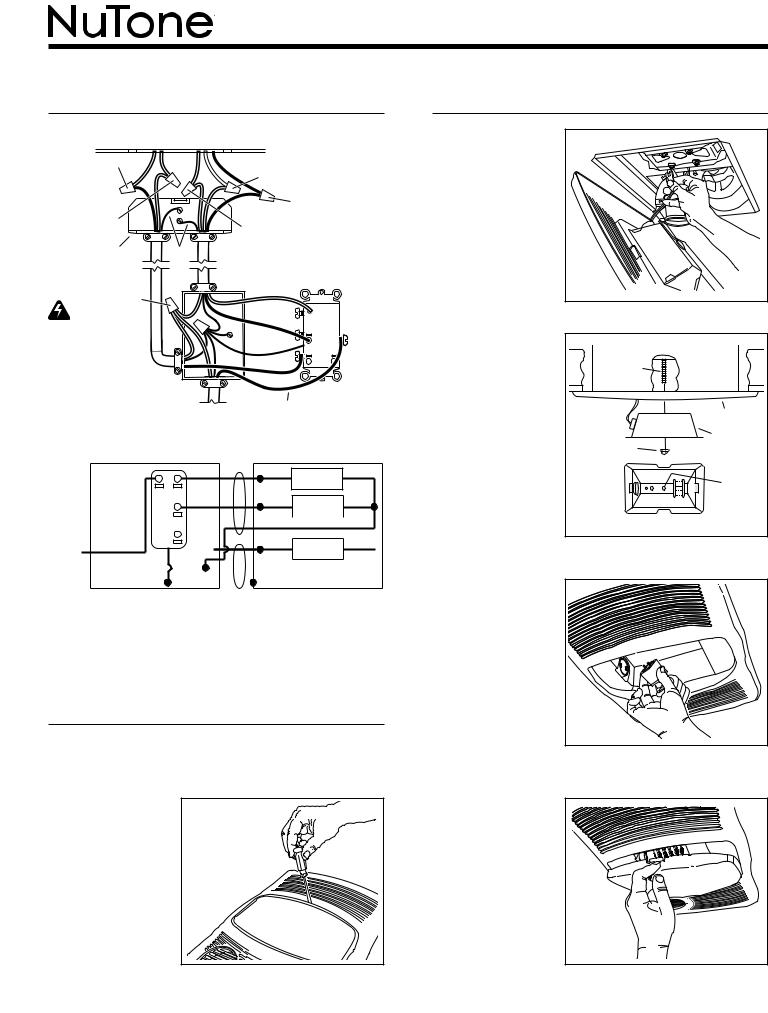
CONNECT WIRING
|
|
LIGHT |
|
|
|
& |
|
|
HEAT |
FAN |
|
|
|
VENTILATOR |
|
BLACK to RED |
|
HOUSING |
|
|
|
||
(Heat) |
|
RED to BLUE |
|
|
|
||
|
|
(Light) |
|
|
|
BLACK to BLACK |
|
|
|
(Fan) |
|
WHITE to WHITE |
|
WHITE to WHITE |
|
|
|
||
WIRING PLATE |
GROUND |
||
FROM VENTILATOR |
|||
|
|
||
WHITE |
|
RED |
|
|
to |
|
|
|
|
WHITE |
|
|
|
LIGHT |
|
|
BLACK |
|
|
caution |
|
|
|
|
|
|
|
FAN |
|
RATING |
|
|
|
|
|
GREEN |
|
|
|
SPECIFICATIONS |
|
BLACK |
|
HEAT |
Each two-position rocker |
|
|
|
|
|
|
|
|
|
switch is rated 15 A @ |
|
|
|
|
120VAC. The total load |
120 VAC LINE IN |
BLACK |
|
|
on this control must not |
|
|
|
|
|
|
|
|
|
exceed 20 A @ 120VAC. |
|
|
|
|
L I G H T |
R E D |
B L U |
L I G H T |
W H T |
S W I T C H |
|
|
|
V E N T |
B L K |
B L K |
V E N T |
W H T |
S W I T C H |
|
|
|
|
H E A T |
|
B L K |
W H T |
|
|
|
|
S W I T C H |
|
|
|
R E D |
|
W H T |
|
|
|
|
|
|||
|
B L K |
|
|
|
H E AT |
||
|
|
|
|
|
|
||
L I N E |
W H T |
|
|
|
W H T |
|
|
I N |
G R D |
G R D |
|
|
|
||
|
|
|
|
||||
D O U B L E - G A N G S W I T C H B OX |
|
U N I T |
|
||||
5. Connect electrical wiring.
Run 120 VAC house wiring to installation location. Use proper UL approved connectors to secure house wiring to wiring plate. Connect wires as shown in wiring diagram(s).
INSTALL GRILLE & BULB
6. Finish ceiling.
Install ceiling material. Cut out ceiling material closely around housing.
7.Remove light lens from grille.
Insert a small flat-bladed screwdriver into the slot at one end of the light lens. Carefully pry the lens out.
MODEL 765HFL
Page
INSTALL GRILLE & BULBS
8. Plug-in light.
Hold grille assembly up near housing. Connect light plug from grille assembly to receptacle inside of housing.
9. |
Attach |
|
|
|
grille. |
SCREW |
|
|
Place grille/ |
|
|
|
|
|
|
|
reflector |
|
|
|
combination |
|
grille |
|
over protruding |
|
|
|
|
light |
|
|
screw and |
acorn nut |
|
|
fasten in place |
reflector |
|
|
|
|
|
|
using acorn nut |
|
use |
|
provided. HAND |
|
|
|
TIGHTEN acorn |
|
this |
|
|
hole |
|
|
nut 1/4 turn after |
|
|
|
bottom view |
||
|
it is snug. |
||
10. Install bulb.
The unit accepts a 27-Watt, 3500K, GU24 fluorescent lamp. Insert tabs on lamp base into slots in lamp receptacle and gently twist lamp clockwise.
11. Attach light lens.
Hook the tabs on one end of the lens into the slot in the grille. Lift other end of lens up and snap into place.
 Loading...