


R
Model SR6300 User Guide
AV Surround Receiver
CAUTION |
RISK OF ELECTRIC SHOCK |
DO NOT OPEN |
CAUTION: TO REDUCE THE RISK OF ELECTRIC SHOCK, |
DO NOT REMOVE COVER (OR BACK) |
NO USER-SERVICEABLE PARTS INSIDE |
REFER SERVICING TO QUALIFIED SERVICE PERSONNEL |
The lightning flash with arrowhead symbol within an equilateral triangle is intended to alert the user to the presence of uninsulated “dangerous voltage” within the product’s enclosure that may be of sufficient magnitude to constitute a risk of electric shock to persons.
The exclamation point within an equilateral triangle is intended to alert the user to the presence of important operating and maintenance (servicing) instructions in the literature accompanying the product.
WARNING
TO REDUCE THE RISK OF FIRE OR ELECTRIC SHOCK,
DO NOT EXPOSE THIS PRODUCT TO RAIN OR MOISTURE.
CAUTION: TO PREVENT ELECTRIC SHOCK, MATCH WIDE
BLADE OF PLUG TO WIDE SLOT, FULLY INSERT.
ATTENTION: POUR ÉVITER LES CHOC ÉLECTRIQUES,
INTRODUIRE LA LAME LA PLUS LARGE DE LA FICHE DANS LA
BORNE CORRESPONDANTE DE LA PRISE ET POUSSER
JUSQU’AU FOND.
NOTE TO CATV SYSTEM INSTALLER:
This reminder is provided to call the CATV (Cable-TV) system installer’s attention to Section 820-40 of the NEC which provides guidelines for proper grounding and, in particular, specifies that the cable ground shall be connected to the grounding system of the building, as close to the point of cable entry as practical.
NOTE:
This equipment has been tested and found to comply with the limits for a Class B digital device, pursuant to Part 15 of the FCC Rules. These limits are designed to provide reasonable protection against harmful interference in a residential installation. This equipment generates, uses and can radiate radio frequency energy and, if not installed and used in accordance with the instructions, may cause harmful interference to radio communications. However, there is no guarantee that interference will not occur in a particular installation. If this equipment does cause harmful interference to radio or television reception, which can be determined by tuning the equipment off and on, the user is encouraged to try to correct the interference by one or more of the following measures:
-Reorient or relocate the receiving antenna.
-Increase the separation between the equipment and receiver.
-Connect the equipment into an outlet on a circuit different from that to which the receiver is connected.
-Consult the dealer or an experienced radio/TV technician for help.
NOTE:
Changes or modifications not expressly approved by the party responsible for compliance could void the user’s authority to operate the equipment.

IMPORTANT SAFETY
INSTRUCTIONS
READ BEFORE OPERATING EQUIPMENT
This product was designed and manufactured to meet strict quality and safety standards. There are, however, some installation and operation precautions which you should be particularly aware of.
1.Read Instructions – All the safety and operating instructions should be read before the product is operated.
2.Retain Instructions – The safety and operating instructions should be retained for future reference.
3.Heed Warnings – All warnings on the product and in the operating instructions should be adhered to.
4.Follow Instructions – All operating and use instructions should be followed.
5.Cleaning – Unplug this product from the wall outlet before cleaning. Do not use liquid cleaners or aerosol cleaners. Use a damp cloth for cleaning.
6.Attachments – Do not use attachments not recommended by the product manufacturer as they may cause hazards.
7.Water and Moisture – Do not use this product near water-for example, near a bath tub, wash bowl, kitchen sink, or laundry tub, in a wet basement, or near a swimming pool, and the like.
8.Accessories – Do not place this product on an unstable cart, stand, tripod, bracket, or table. The product may fall, causing serious injury to a child or adult, and serious damage to the product. Use only with a cart, stand, tripod, bracket, or table recommended by the manufacturer, or sold with the product. Any mounting of the product should follow the manufacturer’s instructions, and should use a mounting accessory recommended by the manufacturer.
9.A product and cart combination should be moved with care. Quick stops, excessive force, and uneven surfaces may cause the product and cart combination to overturn.
10.Ventilation – Slots and openings in the cabinet are provided for ventilation and to ensure reliable operation of the product and to protect it from overheating, and these openings must not be blocked or covered. The openings should never be blocked by placing the product on a bed, sofa, rug, or other similar surface. This product should not be placed in a built-in installation such as a bookcase or rack unless proper ventilation is provided or the manufacturer’s instructions have been adhered to.
11.Power Sources – This product should be operated only from the type of power source indicated on the marking label. If you are not sure of the type of power supply to your home, consult your product dealer or local power company. For products intended to operate from battery power, or other sources, refer to the operating instructions.
12.Grounding or Polarization – This product may be equipped with a polarized alternating-current line plug (a plug having one blade wider than the other). This plug will fit into the power outlet only one way. This is a safety feature. If you are unable to insert the plug fully into the outlet, try reversing the plug. If the plug should still fail to fit, contact your electrician to replace your obsolete outlet. Do not defeat the safety purpose of the polarized plug.
AC POLARIZED PLUG
13.Power-Cord Protection – Power-supply cords should be routed so that they are not likely to be walked on or pinched by items placed upon or against them, paying particular attention to cords at plugs, convenience receptacles, and the point where they exit from the product.
14.Protective Attachment Plug – The product is equipped with an attachment plug having overload protection. This is a safety feature. See Instruction Manual for replacement or resetting of protective device. If replacement of the plug is required, be sure the service technician has used a replacement plug specified by the manufacturer that has the same overload protection as the original plug.
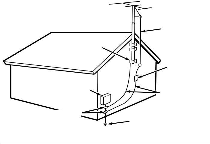
15.Outdoor Antenna Grounding – If an outside antenna or cable system is connected to the product, be sure the antenna or cable system is grounded so as to provide some protection against voltage surges and built-up static charges. Article 810 of the National Electrical Code, ANSI/NFPA 70, provides information with regard to proper grounding of the mast and supporting structure, grounding of the lead-in wire to an antenna discharge unit, size of grounding conductors, location of antenna-discharge unit, connection to grounding electrodes, and requirements for the grounding electrode. See Figure 1.
16.Lightning – For added protection for this product during a lightning storm, or when it is left unattended and unused for long periods of time, unplug it from the wall outlet and disconnect the antenna or cable system. This will prevent damage to the product due to lightning and power-line surges.
17.Power Lines – An outside antenna system should not be located in the vicinity of overhead power lines or other electric light or power circuits, or where it can fall into such power lines or circuits.
When installing an outside antenna system, extreme care should be taken to keep from touching such power lines or circuits as contact with them might be fatal.
18.Overloading – Do not overload wall outlets, extension cords, or integral convenience receptacles as this can result in a risk of fire or electric shock.
19.Object and Liquid Entry – Never push objects of any kind into this product through openings as they may touch dangerous voltage points or short-out parts that could result in a fire or electric shock. Never spill liquid of any kind on the product.
i
20.Servicing – Do not attempt to service this product yourself as opening or removing covers may expose you to dangerous voltage or other hazards. Refer all servicing to qualified service personnel.
21.Damage Requiring Service – Unplug this product from the wall outlet and refer servicing to qualified service personnel under the following conditions:
a.When the power-supply cord or plug is damaged.
b.If liquid has been spilled, or objects have fallen into the product.
c.If the product has been exposed to rain or water.
d.If the product does not operate normally by following the operating instructions. Adjust only those controls that are covered by the operating instructions as an improper adjustment of other controls may result in damage and will often require extensive work by a qualified technician to restore the product to its normal operation.
e.If the product has been dropped or damaged in any way, and
22.Replacement Parts – When replacement parts are required, be sure the service technician has used replacement parts specified by the manufacturer or have the same characteristics as the original part. Unauthorized substitutions may result in fire, electric shock, or other hazards.
23.Safety Check – Upon completion of any service or repairs to this product, ask the service technician to perform safety checks to determine that the product is in proper operating condition.
24.Wall or Ceiling Mounting – The product should be mounted to a wall or ceiling only as recommended by the manufacturer.
25.Heat – The product should be situated away from heat sources such as radiators, heat registers, stoves, or other products (including amplifiers) that produce heat.
f.When the product exhibits a distinct change in performance – this indicates a need for service.
FIGURE 1
EXAMPLE OF ANTENNA GROUNDING AS PER
NATIONAL ELECTRICAL CODE, ANSI/NFPA 70
ANTENNA
LEAD IN
WIRE
GROUND
CLAMP
ANTENNA DISCHARGE UNIT
(NEC SECTION 810-20)
ELECTRIC |
GROUNDING CONDUCTORS |
|
SERVICE |
||
(NEC SECTION 810-21) |
||
EQUIPMENT |
||
|
GROUND CLAMPS
POWER SERVICE GROUNDING ELECTRODE SYSTEM
(NEC ART 250, PART H)
NEC - NATIONAL ELECTRICAL CODE
This Class B digital apparatus complies with Canadian ICES-003.
Cet appareil numérique de la Classe B est conforme à la norme NMB-003 du Canada.
ii

|
|
a |
s |
|
d |
f g h |
j |
|
|
k |
|
|
|
|
|
|
|
|||
|
|
|
|
|
DIGITAL |
|
L R |
|
|
|
|
|
R |
L |
|
|
|
|
|
|
|
|
|
|
|
|
|
|
|
|
|
|
|
|
|
|
|
|
|
||
|
|
|
|
|
IN / OUT |
|
|
|
|
|
|
|
|
|
|
|
|
|
|
|
|
|
|
|
|
|
|
CD |
|
|
|
|
|
|
|
|
R |
L |
|
|
|
|
|
|
L |
R |
|
|
|
OUT |
|
OUT |
|
|
|
|
|
|
|
|
|
|
|
|
|
PRE |
|
|
|
|
|
|
|
|
|
FRONT |
|
|
|
|
|
|
|
|
|
|
OUT |
|
FRONT |
|
TAPE |
|
MONITOR |
|
MONI |
|
|
|
|
|
|
|
|
|
|
|
|
|
|
|
|
TOR |
|
|
|
|
|
|
|
|
|
||||
|
|
|
|
|
|
|
|
|
|
|
|
|
|
|
|
|
|
|
|
|
|
|
|
|
|
DIG- 5 IN |
|
|
|
|
|
|
|
|
|
|
|
|
|
|
|
|
|
ANTENNA |
|
|
OUT |
|
TAPE |
|
VCR1 |
|
VCR1 |
|
|
|
|
|
|
|
|
|
|
|
|
|
SURR. |
|
OUT |
|
|
|
|
|
|
|
|
|
|
|
|||
|
|
|
|
|
|
|
|
|
|
OUT |
|
|
|
|
|
|
|
|
|
|
|
|
|
|
|
DIG- 4 IN L |
R |
|
|
|
|
|
|
|
|
|
|
|
|
|
|
|
|
|
CENTER |
|
SURR. |
CDR |
CDR |
|
DSS / |
|
DSS/ |
|
|
|
|
SPEAKER SYSTEMS B |
|
|
|
|
|
|
|
|
CENTER |
/ MD |
/MD |
|
VCR2 |
|
VCR2 |
|
|
|
|
|
|
|
|||
|
|
|
|
|
|
|
|
|
|
|
|
|
|
|||||||
|
|
AM |
|
|
DIG- 3 IN |
|
|
|
|
|
|
|
SURROUND |
|
|
|
|
|
|
|
|
|
|
SUB |
|
SUB |
VCR1 |
VCR1 |
|
VCR1 |
|
VCR1 |
|
|
|
|
MODEL NO. SR6300 |
|
|
|
|
|
|
|
WOOFER |
|
WOOFER |
|
|
|
|
|
|
|
|
|
||||||
|
|
|
|
|
|
|
|
|
|
|
|
|
|
|
|
|
||||
|
|
GND |
|
|
DIG.OUT COAX |
|
|
|
|
|
|
|
|
|
|
|
|
|
|
|
|
|
|
CENTER |
|
|
DSS / |
DSS/ |
|
DSS / |
|
DSS/ |
|
|
|
|
|
|
|
|
|
|
|
|
|
SURR. |
VCR2 |
VCR2 |
|
VCR2 |
|
VCR2 |
|
|
|
UNSWITCHED |
|
|
|
|
||
|
|
|
|
|
|
|
|
|
|
|
|
|
|
|||||||
|
|
|
|
|
CENTER |
|
|
|
|
|
|
|
|
|
120W 1A MAX |
|
|
|
|
|
|
|
|
|
|
DIG- 2 IN |
|
|
|
|
|
|
|
|
|
|
|
|
|
|
|
|
|
FM |
|
|
|
|
|
|
|
|
|
|
|
|
|
|
|
|
|
|
|
|
(75Ω) |
|
|
SURR. |
|
TV |
|
TV |
|
TV |
|
|
|
|
|
|
|
|
|
|
|
|
|
|
|
|
|
|
|
|
|
|
|
|
|
|
||||
|
|
|
|
|
IN |
OUT |
|
|
|
|
|
|
|
|
|
|
|
|
|
|
|
|
|
|
|
DIG- 1 IN |
|
|
|
|
|
|
|
|
|
SWITCHED |
|
|
|
|
|
|
|
|
|
|
|
|
|
|
|
|
|
|
|
|
120W 1A MAX |
|
|
|
|
|
|
|
|
|
|
FRONT |
|
DVD |
|
DVD |
|
DVD |
|
|
|
|
|
|
|
|
|
|
|
|
6.1CH |
|
|
|
|
|
|
|
|
|
|
|
|
|
|
|
|
|
|
|
|
INPUT |
|
|
|
|
|
|
|
|
|
SURR.CENTER |
CENTER |
|
|
|
|
|
|
|
|
|
L |
R |
DIG.OUT OPT |
|
IN |
IN |
|
IN |
|
|
|
|
|
|
|
|
||
|
|
|
|
|
REMOTE CONTROL |
AUDIO |
VIDEO |
|
S-VIDEO |
|
|
SPEAKER SYSTEMS A |
|
AC OUTLETS |
|
|
|
|||
|
|
|
|
|
|
|
|
|
|
(120V |
60Hz) |
|
|
|
||||||
|
z |
|
|
|
|
|
|
|
|
|
|
|
|
|
|
|
|
|
|
|
|
|
|
l ¡0 ¡1 ¡32 |
¡4 |
¡5 |
|
¡6 |
|
|
|
|
|
|
¡7 ¡8 |
||||||
|
x |
S |
|
|
|
|
|
|
|
|
|
|
|
|
|
|
|
|
|
|
|
|
‹4 |
|
|
|
|
|
|
|
|
|
|
|
|
|
|
|
|
|
|
vc |
|
|
|
|
|
|
|
|
|
|
|
|
|
|
|
|
|
|
||
|
‹3 |
|
|
|
|
|
|
|
|
|
|
|
|
|
|
|
|
|
||
n |
b |
|
|
|
|
|
|
|
|
|
|
|
|
|
|
|
|
|
|
|
m |
|
‹2 |
|
|
|
|
|
|
|
|
FM stereo |
Encoded channel status |
||||||||
|
|
‹1 Night mode |
|
|
|
|
|
|
|
|||||||||||
|
|
|
|
|
|
|
|
|
Tuned |
Auto tuning mode |
|
Speaker |
||||||||
|
|
|
‹0 |
|
Attenuate |
|
|
|
|
|
|
|
|
|||||||
|
, |
|
|
|
|
|
|
|
|
|
|
System |
||||||||
|
|
¤9 |
|
PEAK |
|
Surround mode |
|
|
|
|
|
|
|
|
|
|
Indicator |
|||
|
|
|
¤8 |
|
|
|
|
|
|
|
|
|
|
|
|
|
|
|
|
|
|
. |
|
¤7 |
PEAK |
|
|
|
|
|
|
|
|
|
|
|
|
|
|
|
|
|
|
¤6 |
|
|
|
|
|
DOLBY |
PRO LOGICII |
|
STEREO |
|
|
L |
C |
R |
||||
|
⁄0 |
|
¤5 |
|
ATT |
|
|
|
DIGITAL |
VIRTUAL |
DSP SOUND |
TUNED |
AUTO |
|
SL |
SC |
SR |
|||
|
|
|
|
|
|
|
|
|
|
|
|
|
|
|
|
|
|
|||
⁄1 |
|
¤4 |
|
|
AUTO |
|
DTS ES |
SURROUND EX |
DIRECT |
MEMO PRESET |
|
SW |
|
|||||||
|
⁄2 |
|
¤3 |
|
NIGHT |
|
DIGITAL |
|
|
|
|
|
|
|
|
|
|
|
|
A B |
|
|
|
|
|
|
|
|
|
|
|
|
|
|
|
|
|
||||
|
⁄3 |
|
¤2 |
|
DISPLAY OFF |
ANALOG |
|
|
|
|
|
|
|
|
|
|
|
MUTE |
||
|
|
|
|
|
PCM |
|
|
|
|
|
|
|
|
|
|
SLEEP |
||||
⁄4 |
|
|
|
HT-EQ |
|
|
|
|
|
|
|
|
|
|
|
|
|
|
|
|
|
⁄5 |
|
|
|
|
|
|
|
|
|
|
|
|
|
|
Preset channel |
|
|
||
|
⁄6 |
|
¤1 |
|
HT-EQ |
|
|
|
|
|
|
|
|
|
|
|
|
|||
|
|
|
|
Input indicator |
|
|
|
|
|
|
Memory |
|
Sleep timer |
|||||||
|
⁄7 |
|
¤0 |
Display off |
|
|
|
|
|
|
|
|
||||||||
|
|
|
|
|
|
|
|
|
|
|
Direct mode |
|
|
|
|
Mute |
||||
|
|
|
|
|
|
|
|
|
|
|
|
|
|
|
|
|
||||
|
⁄8 |
|
|
|
|
|
|
|
|
|
|
|
|
|
|
|
|
|
|
|
|
⁄9 |
|
|
|
|
|
|
|
|
|
|
|
|
|
|
|
|
|
|
|
|
|
|
|
|
|
!2 |
!3 |
|
!4 |
!5 !6!7 |
|
|
|
|
||||||
|
|
|
|
|
y |
|
u |
i |
|
|
|
|
o |
|
!0 |
|
|
|
!1 |
|
|
|
|
e |
|
|
|
|
|
|
|
|
|
|
|
|
|
|
r |
|
|
|
AV SURROUND RECEIVER SR6300 |
SURROUND |
VOLUME |
|
|
PEAK |
|
|
DOLBY |
PRO LOGICII |
STEREO |
RDS |
|
L |
C |
R |
|
|
|
|
|
|
|
ATT |
|
|
DIGITAL |
VIRTUAL |
DSP SOUND |
TUNED |
AUTO PTY |
RT SL |
SC |
SR |
|
|
|
|
|
|
|
|
|
AUTO |
DTS ES |
SURROUND EX |
DIRECT |
MEMO |
PRESET |
SW |
|
|
|
|
|
||
|
|
NIGHT |
|
DIGITAL |
|
|
|
|
|
|
|
|
|
|
|
|
|
|
|
DISPLAY OFF |
ANALOG |
|
|
|
|
|
|
|
MUTE |
|
|
|
|
||
|
|
|
|
PCM |
|
|
|
|
|
|
|
SLEEP |
|
DOWN |
|
UP |
|
|
|
|
|
|
|
|
|
|
|
|
|
|
|
|
|||
|
|
HT-EQ |
|
|
|
|
|
|
|
|
|
|
|
|
|
|
|
|
|
|
CLEAR |
MEMORY |
|
|
TUNING/PRESET |
|
|
F/P |
|
|
MODE |
|
|
|
|
|
|
|
|
|
|
|
|
|
|
|
|
|
|
|
|
|
MUTE |
A |
SPEAKERS B |
6.1CH IN |
|
A/D |
|
|
S-DIRECT |
|
SLEEP |
|
|
|
DIMMER |
|
|
|
|
STANDBY |
|
|
|
|
|
|
|
|
|
|
|
|
|
|
|
|
|
|
|
|
|
|
|
|
|
|
|
|
|
|
|
|
|
AUX INPUT |
|
POWER ON/STANDBY |
PHONES |
TV |
DVD |
VCR1 |
DSS/VCR2 |
AUX |
CDR/MD |
TAPE |
|
|
CD |
TUNER |
S-VIDEO |
VIDEO |
L AUDIO R |
||
q |
w |
t |
|
!9 |
!8 |
iii

TABLE OF CONTENTS |
|
INTRODUCTION ............................................ |
2 |
DESCRIPTION............................................... |
2 |
FEATURES .................................................... |
3 |
FRONT PANEL FEATURES .......................... |
4 |
REAR PANEL CONNECTIONS..................... |
5 |
REMOTE CONTROLER RC7300SR ............. |
6 |
NAMES AND FUNCTIONS .................................................................... |
6 |
REMOTE CONTROL RANGE ............................................................... |
8 |
LOADING BATTERIES .......................................................................... |
8 |
GENERAL INFROMATION OF RC7300SR TO SR6300 ....................... |
8 |
CONNECTIONS............................................. |
9 |
SPEAKER PLACEMENT ....................................................................... |
9 |
CONNECTING SPEAKERS ................................................................. |
10 |
CONNECTING AUDIO COMPONENTS .............................................. |
11 |
CONNECTING VIDEO COMPONENTS .............................................. |
12 |
ADVANCED CONNECTING ................................................................ |
13 |
CONNECTING REMOTE CONTROL JACKS ...................................... |
13 |
CONNECTING THE ANTENNA TERMINALS ...................................... |
14 |
SETUP ......................................................... |
15 |
ON SCREEN DISPLAY MENU SYSTEM............................................. |
15 |
INPUT SETUP (ASSIGNABLE DIGITAL INPUT) ................................. |
16 |
SPEAKER SETUP ............................................................................... |
16 |
PREFERENCE ..................................................................................... |
18 |
SURROUND ........................................................................................ |
18 |
PL2 (PRO LOGIC II) MUSIC PARAMETER ......................................... |
18 |
CS2 (CIRCLE SURROUND II) PARAMETER ..................................... |
19 |
6.1 CH INPUT LEVEL .......................................................................... |
19 |
BASIC OPERATION .................................... |
20 |
LISTENING TO THE TUNER ............................................................... |
20 |
PLAYBACK OPERATION .................................................................... |
21 |
TV AUTO ON/OFF FUNCTION ............................................................ |
21 |
SETTING THE SLEEP TIMER ............................................................. |
22 |
ADJUSTING THE SURROUND LEVEL ............................................... |
22 |
ON SCREEN DISPLAY INFOMATION ........ |
23 |
REMOTE CONTROLLER OPERATION ..... |
24 |
CONTROLLING THE SR6300 ............................................................. |
24 |
CONTROLLING MARANTZ COMPONENTS ...................................... |
24 |
LEARN MODE ..................................................................................... |
26 |
MACRO MODE .................................................................................... |
27 |
SURROUND MODE ..................................... |
31 |
TROUBLE SHOOTING ................................ |
35 |
TECHNICAL SPECIFICATIONS.................. |
37 |
DIMENSION ................................................. |
37 |
ENGLISH
1
ENGLISH |
INTRODUCTION |
Please take a few minutes to read this manual thoroughly before you |
|
|
Thank you for purchasing the Marantz SR6300 DTS/Dolby Digital |
|
Surround receiver. |
|
This remarkable component has been engineered to provide you with |
|
many years of home theater enjoyment. |
|
connect and operate the SR6300. |
|
As there are a number of connection and configurations options, you |
|
are encouraged to discuss your own particular home theater setup |
|
with your Marantz A/V specialist dealer. |
DESCRIPTION
DTS was introduced in 1994 to provide 5.1 channels of discrete digital audio into home theater systems.
DTS brings you premium quality discrete multi-channel digital sound to both movies and music.
DTS is a multi-channel sound system designed to create full range digital sound reproduction.
The no compromise DTS digital process sets the standard of quality for cinema sound by delivering an exact copy
of the studio master recordings to neighborhood and home theaters.
Now, every moviegoer can hear the sound exactly as the moviemaker intended.
DTS can be enjoyed in the home for either movies or music on of
DVD’s, LD’s, and CD’s.
“DTS” and “DTS Digital Surround” are registered trademarks of Digital
Theater Systems, Inc.
The advantages of discrete multichannel systems over matrix are well known.
But even in homes equipped for discrete multichannel, there remains a need for high-quality matrix decoding. This is because of the large library of matrix surround motion pictures available on disc and on
VHS tape; and analog television broadcasts.
The typical matrix decoder of today derives a center channel and a mono surround channel from two-channel matrix stereo material. It is better than a simple matrix in that it includes steering logic to improve separation, but because of its mono, band-limited surround it can be disappointing to users accustomed to discrete multichannel.
Neo 6 offers several important improvements as follow,
•Neo 6 provides up to six full-band channels of matrix decoding from stereo matrix material. Users with 6.1 and 5.1 systems will derive six and five separate channels, respectively, corresponding to the standard home-theater speaker layouts.
•Neo 6 technology allows various sound elements within a channel or channels to be steered separately, and in a way which follows naturally from the original presentation.
•Neo 6 offers a music mode to expand stereo nonmatrix recordings into the fiveor six-channel layout, in a way which does not diminish the subtlety and integrity of the original stereo recording.
DTS-ES Extended Surround is a new multi-channel digital signal format developed by Digital Theater Systems Inc. While offering high compatibility with the conventional DTS Digital Surround format, DTSES Extended Surround greatly improves the 360-degree surround impression and space expression thanks to further expanded surround signals. This format has been used professionally in movie theaters since 1999.
In addition to the 5.1 surround channels (FL, FR, C, SL, SR and LFE), DTS-ES Extended Surround also offers the SC (Surround Center) channel for surround playback with a total of 6.1 channels. DTS-ES Extended Surround includes two signal formats with different surround signal recording methods, as DTS-ES Discrete 6.1 and DTS-
ES Matrix 6.1.
“DTS”, “DTS-ES Extended Surround” and “Neo:6” are trademarks of Digital Theater Systems, Inc.
Dolby Digital identifies the use of Dolby Digital (AC-3) audio coding for such consumer formats as DVD and DTV. As with film sound, Dolby Digital can provide up to five full-range channels for left, center, and right screen channels, independent left and right surround channels, and a sixth ( “.1”) channel for low-frequency effects.
Dolby Surround Pro Logic II is an improved matrix decoding technology that provides better spatiality and directionality on Dolby
Surround program material; provides a convincing three-dimensional soundfield on conventional stereo music recordings; and is ideally suited to bring the surround experience to automotive sound. While conventional surround programming is fully compatible with Dolby
Surround Pro Logic II decoders, soundtracks will be able to be encoded specifically to take full advantage of Pro Logic II playback, including separate left and right surround channels. (Such material is also compatible with conventional Pro Logic decoders.)
Dolby Digital EX creates six full-bandwidth output channels from 5.1- channel sources. This is done using a matrix decoder that derives three surround channels from the two in the original recording. For best results, Dolby Digital EX should be used with movies soundtracks recorded with Dolby Digital Surround EX.
“Dolby”, “Pro Logic”, and the double-D symbol are trademarks of
Dolby Laboratories.
Circle Surround II (CS-II) is a powerful and versatile multi-channel technology. CS-II is designed to enable up to 6.1 multi-channel surround sound playback from mono, stereo, CS encoded sources and other matrix encoded sources. In all cases the decoder extends it into 6 channels of surround audio and a LFE/subwoofer signal. The CS-II decoder creates a listening environment that places the listener “inside” music performances and dramatically improves both hi-fi audio conventional surround-encoded video material. CS-II provides composite stereo rear channels to greatly improve separation and image positioning – adding a heightened sense of realism to both audio and A/V productions.
CS-II is packed with other useful feature like dialog clarity (SRS Dialog) for movies and cinema-like bass enrichment (TruBass). CS-II can enable the dialog to become clearer and more discernable in movies and it enables the bass frequencies contained in the original programming to more closely achieve low frequencies – overcoming the low frequency limitations of the speakers by full octave.
SRS Circle Surround II, SRS Dialog, SRS TruBass, SRS and symbol are trademarks of SRS Labs, Inc.
SRS Circle Surround II, SRS Dialog and SRS TruBass technology are incorporated under license from SRS Labs, Inc.
2

FEATURES
BUILT-IN 6 CHANNEL POWER AMPLIFIER
100 watts to each of the six main channels ; the power amp section features an advanced, premium highstorage power supply capacitors, and fully discrete output stages housed in cast aluminum heat sinks .
192 kHZ/24-BIT D/A CONVERTER FOR ALL CHANNELS
High performance digital circuitry with 192 kHz / 24-bit D/A converter for all 7 channels.
DTS-ES
DTS-ES decoder built in to decode the impeccable 6.1-channel discrete digital audio from DTS-ES encoded DVD-Video discs, DVDAudio discs and CDs.
DOLBY DIGITAL EX
Dolby Digital EX decoder built in to create six full-band width output channels from the 5.1-channel digital audio of DVDs, Digital TV, HDTV, satellite broadcasts and other sources.
DOLBY PRO LOGIC II
Dolby Pro Logic II decoder provides better spatiality and directionality on Dolby Surround program material and provides a convincing three-dimensional sound field on conventional stereo music recordings.
DTS-NEO6
DTS-Neo6 decoder built in to decode 6.1-channel surround sound from any stereo material.
CIRCLE SURROUND II
CIRCLE SURROUND II decoder built in to decode 6.1-channel surround sound from any stereo or passive matrix-encoded material.
SOURCE DIRECT MODE
Source Direct mode bypasses, tone controls and bass management for purest audio quality.
6.1 CHANNEL PRE-AMP OUTPUTS
6.1 channel pre-amp outputs for connection to external components such as a subwoofer and external power amplifiers.
6.1CH DIRECT INPUT
6.1ch direct inputs accommodate future multi-channel sound formats or an external digital decoder.
5 DIGITAL INPUTS AND 2 DIGITAL OUTPUTS
5 Digital inputs for connection to other sources, such as DVD, DSS,
CD, CD-R or MD.
2 Digital outputs for connection to CD-R or MD.
ONSCREEN DISPLAY MENU SYSTEM
Easy to use on-screen display menu system in all video monitor output.
ENGLISH
3

ENGLISH |
FRONT PANEL FEATURES |
When this switch is pressed once, the unit turns ON and display |
|
|
(SEE PAGE iii.) |
|
q POWER switch and STANDBY indicator |
|
appears on the display panel. When pressed again, the unit turns OFF |
|
and the STANDBY indicator lights. |
|
When this unit is in the standby mode, pressing one of the FUNCTION |
|
SELECTOR buttons also allows to turn the power on. |
|
|
|
“When the STANDBY indicator lights up, the apparatus is NOT |
|
disconnected from the AC supply mains.” |
|
|
|
w PHONES jack for stereo headphones |
|
Conventional dynamic headphones can be plugged in here. |
|
Notes: |
•When using headphones, turn off the speakers systems A and B with SPEAKERS buttons. The surround mode is switched automatically to STEREO.
e SURROUND mode selector knob
When this knob is turned, the surround mode is switched sequentially.
r VOLUME control knob
Adjusts the over all sound level. Turning the control clockwise increases the sound level.
t Function selector buttons (Audio/
Video)
These buttons are used to select the sources.
The video function selector, such as TV, DVD , VCR1, DSS/VCR2, and AUX, selects video and audio simultaneously.
Audio function sources such as CD, TAPE , CDR/MD ,and TUNER may be selected in conjunction with a Video source.
This feature (Sound Injection) combines a sound from one source with a picture from another.
Choose the video source first, and then choose a different audio source to activate this function.
y 6.1CH IN button
Press this button to select the output of an external multi channel decoder.
u A/D (Analog/Digital) SELECTOR button
This is used to select between the analog and digital inputs.
Note:
•This button is not used for an input source that is not connected to a digital input.
i S- ( Source) DIRECT button
When this button is pressed, the tone control circuit is bypassed as well as Bass Management.
Notes:
•The surround mode is automatically switched to AUTO when the source direct function is turned on.
•Additionally, Speaker Configurations are fixed automatically as follow.
Front SPKR = LARGE Center SPKR = LARGE Surround SPKR = LARGE Surround Center SPKR = YES Sub woofer = YES
•S-DIRECT is turned off when the other surround mode is selected with the SURROUND mode selector knob or the surround mode buttons of the remote controller.
•S-DIRECT is not available for speaker systems B.
o SLEEP (Sleep timer) button
Set the sleep timer function with this button .
!0DIMMER button
When this button is pressed once, the display is dimmed.
When this button is pressed twice, the display is turned off and “DISPLAY OFF” indicator lights up.
Press this button again to turn the display ON again.
!1MUTE button
Press this button to mute the output to the speakers. Press it again to return to the previous volume level.
!2CLEAR button
Press this button to cancel the station memory setting mode or preset scan tuning.
!3MEMORY button
Press this button to enter the tuner preset memory numbers and station names.
!4TUNING / PRESET UP and DOWN buttons
During reception of AM or FM, you can scan the other frequencies or select another preset station pressing these buttons.
!5F/P (Frequency/ Preset) button
During reception of AM or FM, you can change the function of the UP/ DOWN buttons for scanning frequencies or selecting preset stations by pressing this button.
!6(FM) MODE button
Press this button to select the auto stereo mode or mono mode when the FM band is selected. The AUTO indicator lights in the auto stereo mode.
!7Infrared sensor
This window receives infrared signals from the remote control unit.
!8AUX input jacks
These auxiliary video/audio input jacks accept the connection of a camcorder, portable VCR, etc.
!9SPEAKERS buttons
Press these buttons to select speakers systems A and/or B.
4

REAR PANEL CONNECTIONS (SEE PAGE iii.)
All connections to the rear panel should be made with the entire system powered off.
To avoid errors, it is advisable to connect one cable at a time between the various components.
a FM antenna terminal (75 ohms)
Connect an external FM antenna with a coaxial cable, or a cable network FM source.
AM antenna and ground terminals
Connect the supplied AM loop antenna. Use the terminals marked “AM” and “GND”.
The supplied AM loop antenna will provide good AM reception in most areas.
Position the loop antenna until you hear the best reception.
s PRE OUT jacks
Jacks for Front - L/R, Center,Surround-L/R and Surround center.
Use these jacks for connection to an external power amplifier.
d SUB WOOFER output jack
Connect to the input jack(s) of the power amplifier for subwoofer channel or powered subwoofer.
f Analog AUDIO outputs for audio recording equipment
TAPE and CD-R/MD
Connect each output to the audio inputs (REC in) of your recording equipment.
g Analog AUDIO inputs
CD, TAPE, and CD-R/MD
Connect the audio outputs of your source components to the input jacks on the receiver.
h VIDEO (VIDEO/S-VIDEO) outputs
VCR1, and DSS/VCR2
Connect each output to the video input (REC in) of your video recording equipment.
j TV MONI. (VIDEO/S-VIDEO) output jacks
Connect the TV MONI jack to your TV’s video input (VIDEO IN) jack.
You can connect your video equipment with S-VIDEO jacks if possible, or the composite VIDEO jacks.
You must use the same type of connection from your video player into the receiver, and out of the receiver into your TV.
Both must be composite video or both must be S-Video. You cannot convert a signal from one type to the other.
k SPEAKER SYSTEMS terminals
SPEAKER SYSTEMS A TERMINALS
FRONT Left & Right speakers output terminals
Connect to the front left & right speakers.
CENTER speaker output terminals
Connect to the center speaker.
SURROUND Left & Right speakers output terminals
Connect to the surround (rear) left & right speakers.
SURROUND Center speaker output terminals
Connect to the surround center speaker.
SPEAKER SYSTEMS B TERMINALS
FRONT Left & Right speakers output terminals
Connect to the front left & right speakers.
Notes:
•When you use the speaker systems A and B simultaneously, the connected speakers which are impeadance 12 to 16 ohms must be used.
l 6.1 CH INPUT jacks
Connect to the outputs of DVD Audio player, SACD Multi channel player or an external multichannel decoder.
¡0DIGITAL outputs
Optical and Coaxial
Connect to the digital input of your digital recording equipment.
¡1DIGITAL inputs
Dig.1,2 (Optical) and Dig. 3, 4, 5 (Coaxial)
Connect each input to the digital output of your source equipment. Use the SETUP MAIN MENU to assign digital input to appropriate source. (see page 16)
Note :
•The coaxial connections are not for AC-3 RF from the LD player, If you want to decode this type of signal, an external demodulator must be used.
¡2REMOTE CONTOROL IN/OUT terminals
Connect to a Marantz component equipped with remote control (RC- 5) terminals.
¡3Analog AUDIO outputs for video recording equipment
VCR1, and DSS/VCR2
Connect each output to the audio inputs (REC in) of your video recording equipment.
¡4Analog AUDIO inputs for video source equipment
TV, DVD, VCR1, and DSS/VCR2
Connect each input to the audio outputs of your video source equipment.
¡5VIDEO inputs
TV, DVD, VCR1, and DSS/VCR2
Connect each input to the video outputs of your video source equipment.
¡6S-VIDEO inputs
TV, DVD, VCR1, and DSS/VCR2
Connect each input to the S-video outputs of your video source equipment.
¡7AC OUTLET
Connect the power cables of components such as a DVD and CD player to these outlets. Both SWITCHED and UNSWITCHED outlets are provided.
The one marked SWITCHED provides power only when the SR6300 is turned on and is useful for components which you use every time you play your system.
The one marked UNSWITCHED is always live as long as the SR6300 is plugged into a live outlet.
A component connected here may be left on permanently, or may be switched off with its own power switch.
Caution:
•In order to avoid potential turn-off thumps, anything plugged in here should be powered up BEFORE the SR6300 is turned on.
•The capacity of this AC outlet is 120W. Do not connect devices that consume electricity more than the capacity to this AC outlet. If total power consumption of connected devices exceeds the capacity, protection circuit shuts down the power supply.
¡8Power Cable
Connect to AC power outlet.
SR6300 can be powered by 120V AC only.
ENGLISH
5
ENGLISH
REMOTE CONTROLER RC7300SR
NAMES AND FUNCTIONS
z Infrared window
Outputs and inputs an infrared control signals.
x LCD (Liquid Crystal Display)
Used to display information about currently selected functions.
c / (open/close) button
Used to open or close the door.
v Source POWER ON/OFF button
Used to turn specific sources (such as DVD players, etc.) ON and OFF independently from the rest of the system.
b EQ button
Used to turn on or off HT (Home Theater)-EQ mode when the surround mode is set as AUTO, DOLBY, DTS or STEREO.
This mode compensates for the audio portion of a movie sounding “bright”. When this button is pressed, “HT-EQ” indicator lights up.
n V-OFF (video off) button
Used to turn off the video signal.
Note:
• This button is unavailable for SR6300.
m DVD operating buttons
(when DVD mode is selected)
AUDIO button
Used to select one of the audio language.
ANGLE button
Used to change the different camera angle.
SUBTITLE button
Used to select one of the subtitle language.
, Numeric buttons 1 to 9, 0 / Surround mode buttons
Numeric buttons
Used to enter figures in the selection of a tuner preset station and station name preset or to set select a CD track number, etc. The functions of these buttons are dependent on the function button selected.
Surround mode buttons (when AMP mode is selected)
Used to select the surround mode.
. CL (clear) / S-DIRECT (source direct) button
Used to cancel for certain memory or programming operations.
(when AMP mode is selected)
Used to select the S-DIRECT (source direct) mode. In source direct mode, the tone control circuitry is bypassed.
⁄0INPUT button
Used to select monitor input.
⁄1T.MODE button
(when TUNER mode is selected)
Used to select the auto stereo mode or mono mode when the FM band is selected.
The “AUTO” indicator lights in the auto stereo mode.
⁄2(TV) CH 3/4 buttons
Used to increase or decrease the TV channel.
⁄3TOP MENU button
(when DVD mode is selected)
Used to call up the top menu of the DVD.
⁄4Tone / Deck cotrol buttons
Tone cotrol buttons (when AMP mode is selected)
The TREBLE buttons are used to adjust the tone control of high frequency sound for left and right speaker.
The BASS buttons are used to adjust the tone control of low frequency sound for left, right and subwoofer speaker.
Deck cotrol buttons (when Tape mode is selected)
The DECK A button are used to select the deck A. The DECK B button are used to select the deck B.
The 1 2 button are used to change the direction.
⁄5CURSOR / OK button
Used to operate on-screen and other displays used by receivers and other components.
⁄6CH SEL. (channel select) button
(when AMP mode is selected)
Used to call up SETUP MAIN MENU and adjust speaker levels or 6.1 ch input level.
⁄7SETUP button
(when DVD mode is selected)
Used to call up the setup menu of the DVD.
⁄8CONTROL buttons
These buttons are used when operating the CD player, TAPE deck, etc. The function of these buttons are dependent on the function button selected.
(when AMP mode is selected)
SPK A/B button
Speaker mode is switched in the following sequence. A → B → A+B → off
ATT button
When the input signal is too high and the voice distorts even by throttling the SR6300 VOLUME control, turn on this function. “ATT” is indicated when this function is activated.
The input level is reduced. Attenuator is invalid for use with the output signal of “REC OUT”.
Note:
• This function is unavailable during the digital input is selected.
MULTI button
This button is unavailable for SR6300.
⁄9Input selector buttons/ FUNCTION SE-
LECTOR buttons (AUDIO/VIDEO INPUT)
Used to switch the remote controller to the command sets for specific sources (amplifier, receiver, etc.), thereby allowing a single remote controller to control up to 11 different components. To use these buttons to switch the amplifier’s source, press the desired button twice within 2 seconds. The AMP button ⁄9is used only to switch command set of the remote controller itself and therefore does not transmit any signal. Further, the function buttons may also be programmed to execute macros. (A macro allows a complex string of operations to be performed in series simply by pressing a single button.) One button can be programmed to learn sequences containing up to 10 commands. The following is an example of such a sequence that can be activated automatically using a macro:
Turn the receiver ON → Switch the function to DVD → Set the Surround Mode to VIRTUAL → Set the DVD player to Play.
Note:
• The AUX2 button is unavailable for SR6300.
6
¤0EXIT button
(when AMP mode is selected)
Used to exit SETUP MAIN MENU or On Screen Display.
¤1TEST button
(when AMP mode is selected)
Used to enter the test tone menu.
¤2MENU/OSD button
(when AMP mode is selected)
When this button is pressed, the current setting are displayed on the TV monitor.
¤3VOLUME  /
/  buttons
Used to adjust the volume on receivers and other components equipped with volume control.
¤4P.SCAN (preset scan) button
(when TUNER mode is selected)
Used to start preset scan when SR6300 is selected TUNER mode.
¤5MUTE button
Muting button of the SR6300. Press this button decrease the sound temporarily . Press this button again to return to the previous sound.
When this button is pressed, “MUTE” indicator lights up.
¤6MEMO button
Memory enable button for various preset functions.
¤7NIGHT button
(when AMP mode is selected)
Pressing this button prevents the Dolby Digital signal from playback at a loud voice. This function reduces the voice by 1/3 to 1/4 at maximum.
Thus, it eliminates the occurrence of an abruptly loud voice at night. However, the function is valid only for the case when the Dolby Digital signal is entered into OPTICAL or COAXIAL and data to compress the voice exists in the signal to be played back.
When this button is pressed, “NIGHT” indicator lights up.
¤8PTY button
(when TUNER mode is selected)
Used to display the programme type information of the current station.
The RDS system categorizes programmes according to their genre into different programme type (PTY) groups.
Note:
• This button is unavailable for SR6300.
¤9F.DIR/SEAR button
(when TUNER mode is selected)
Used to select the mode of frequency direct input.
‹0DISP./RDS button
(when TUNER mode is selected)
Selects display mode function in RDS (Radio Data System) by this button.
Note:
• This button is unavailable for SR6300.
(when AMP mode is selected)
When this button is pressed once, the display is dimmed.
When this button is pressed twice, the display is turned off and
“DISPLAY OFF” indicator lights up.
Press this button again to turn the display ON again.
‹1A/D button |
ENGLISH |
|
This is used to switch between the analog and digital inputs. |
||
|
‹2SLEEP (sleep timer) button
This button is used for setting the sleep timer. It can be operated the same way as the button in unit.
‹37.1/6.1CH IN button
Press this button to select the output of an external multi channel decoder.
‹4POWER ON OFF buttons
(when AMP mode is selected)
Press to switch the power of the SR6300 ON or OFF.
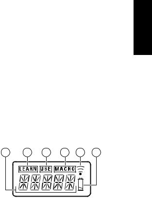
LCD (Liquid Crystal Display)
Information about currently selected functions and modes is displayed on the LCD.
a |
b c d e f |
a Function Name indicator
Displays the name of the currently selected function (DVD, TV, etc.) using up to 5 characters.
b LEARN indicator
Indicates when the remote controller is in the LEARN mode.
c USE indicator
For normal operation the USE indicator is displayed.
d MACRO indicator
Indicates when the remote controller is in the MACRO mode.
e Transmission indicator
Indicates when the remote controller is transmitting a signal.
f Low battery indicator
When this indicator appears, the batteries should be replace.
7
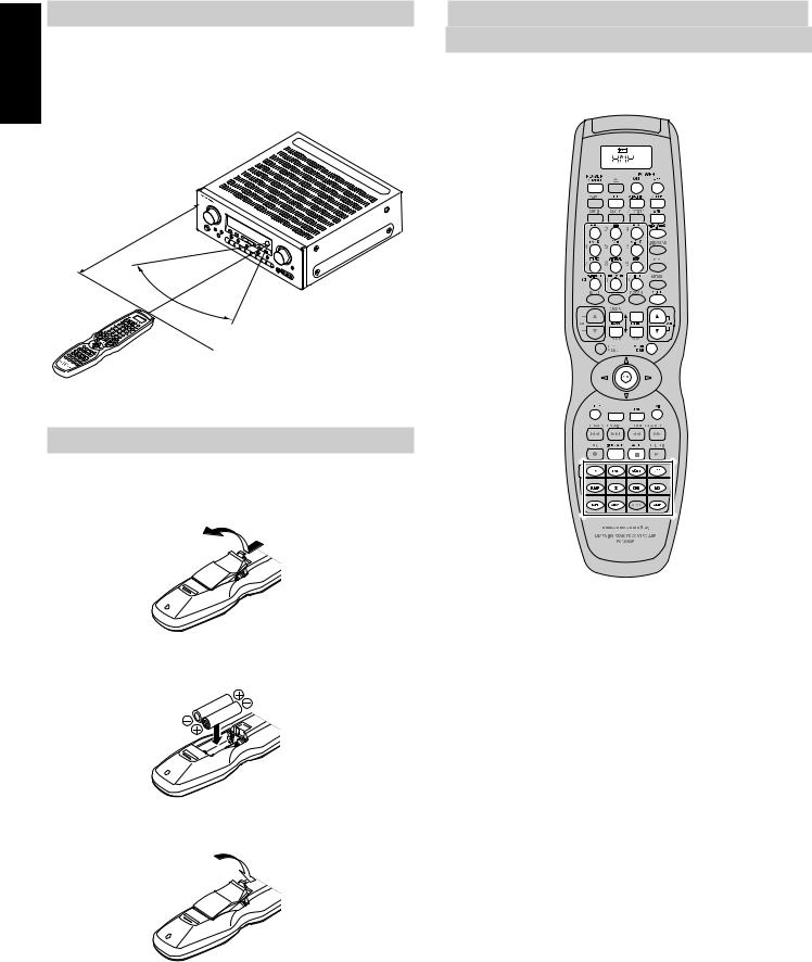
ENGLISH |
REMOTE CONTROL RANGE |
|
The distance between the transmitter of the remote control unit and |
||
|
||
|
the IR SENSOR of the SR6300 should be less than about 5 meters. If |
|
|
the transmitter is pointed to a direction other than the IR SENSOR or if |
|
|
there is an obstacle between them, remote control may not be |
|
|
possible. |
|
|
Remote-controllable range |
|
|
SR6300 |
|
|
m |
|
5 |
|
. |
|
|
Approx |
|
|
60°
Remote control unit (RC7300SR)
LOADING BATTERIES
The life of the batteries used with the remote control unit is about 4 months with normal use. Also be sure to replace batteries earlier when you notice that they are getting weak.
1. Remove the back cover.
2. Insert the new batteries (AA type) with correct (+) and (–) polarity.
3. Close until it clicks.
Note:
•The supplied batteries are shipped to confirm the initial operation. Therefore, the supplied batteries will be consumed quickly.
GENERAL INFROMATION OF RC7300SR
TO SR6300
To control the SR6300 by your RC7300SR, you have to select the device AMP by function selector button. Please refer as below for the details in AMP mode.
POWER ON/OFF |
Turns the SR6300 on and off |
|
POWER ON |
|
Turns the SR6300 on |
|
|
|
POWER OFF |
|
Turns the SR6300 off |
|
|
|
EQ |
|
Turns on or off HT-EQ mode |
7.1/6.1 IN |
|
Selects the 6.1CH IN |
|
|
|
SLEEP |
|
Sets the sleep timer function |
|
|
|
A/D |
|
Switches between the analog and digital inputs |
DISP./RDS |
|
Changes the brightness of the front display |
|
|
|
Surround mode |
|
Selects the surround mode |
(0-9) |
|
|
|
|
|
S-DIRECT |
|
Selects the Source Direct mode |
NIGHT(+10) |
|
Turns on or off NIGHT mode |
|
|
|
MUTE |
|
Decreases the sound temporarily |
|
|
|
BASS 34 |
|
Adjusts the tone control of low frequency sound |
TREBLE 34 |
|
Adjusts the tone control of high frequency sound |
|
|
|
VOL 34 |
|
Adjusts the over all sound level |
|
|
|
MENU/OSD |
|
Displays the current setting on the monitor |
Cursor |
|
Moves the cursor for setting in “On screen display” mode |
|
|
|
OK |
|
• Enter the “On screen display” |
|
|
|
|
|
• Confirms the setting in “On screen display” mode |
SETUP |
|
Same as OK button |
|
|
|
CH SEL |
|
Calls up SETUP MAIN MENU and adjusts speaker levels or 6.1ch input level |
|
|
|
TEST |
|
Enters the test tone menu |
EXIT |
|
Exits from SETUP MAIN MENU |
|
|
|
SPKR A/B |
|
Selects the speaker system |
|
|
|
ATT |
|
Reduces the input level |
Function selector |
Selects a particular source component |
|
|
|
|
8
 Loading...