


LG 4422LLHH2200, 3377LLHH2200, 3322LLHH3300, 1199LLUU5500, 4422LLHH3300 User Manual
...Trade Mark of the DVB Digital Video Broadcasting Project (1991 to 1996)
ID Number(s): ?? : 19LU4000 ?? : 19LU4010 ?? : 22LU4000 ?? : 22LU4010 ?? : 19LU5000 ?? : 19LU5010 ?? : 19LU5020 ?? : 22LU5000 ?? : 22LU5010 ?? : 22LU5020 ?? : 26LU5000 ?? : 26LU5010 ?? : 26LU5020
6200: 19LH2000 ?? : 19LH2010
?? : 19LH2020 6201: 22LH2000 ?? : 22LH2010
?? : 22LH2020 6202: 26LH2000 ?? : 26LH2010
?? : 26LH2020 6203: 32LH2000 ?? : 32LH2010
?? : 32LH2020 6204: 37LH2000 ?? : 37LH2010
?? : 37LH2020 6205: 42LH2000 ?? : 42LH2010
?? : 42LH2020 6206: 32LH3000 ?? : 32LH3010
?? : 32LH3020 ?? : 32LH3030
6208: 37LH3000 ?? : 37LH3010
?? : 37LH3020 ?? : 37LH3030
6209: 42LH3000 ?? : 42LH3010
?? : 42LH3020 ?? : 42LH3030 6210: 47LH3000 ?? : 47LH3010 ?? : 47LH3020 ?? : 47LH3030 6211: 32LH4000 ?? : 32LH4020 ?? : 32LH4010 6212: 37LH4000 ?? : 37LH4020 ?? : 37LH4010 6213: 42LH4000 ?? : 42LH4020 ?? : 42LH4010 6214: 47LH4000 ?? : 47LH4020 ?? : 47LH4010
??: 32LH5000
??: 32LH5020
??: 32LH5010 ??: 37LH5000
??: 37LH5020
??: 37LH5010 ??: 42LH5000
??: 42LH5020
??: 42LH5010 ??: 47LH5000
??: 47LH5020
??: 47LH5010 6195: 32LH7000
??: 32LH7010
??: 32LH7020
??: 32LH7030 6196: 37LH7000
??: 37LH7010
??: 37LH7020
??: 37LH7030 6197: 42LH7000
??: 42LH7010
??: 42LH7020
??: 42LH7030 6198: 47LH7000
??: 47LH7010
??: 47LH7020
??: 47LH7030
??: 32LF2500
??: 37LF2500
??: 42LF2500
??: 32LH4900
??: 37LH4900
??: 42LH4900
??: 47LH4900 6191: 50PS7000 6192: 60PS7000 6193: 50PS8000 6194: 60PS8000
ENGLISH
LCD TV |
PLASMA TV |
OWNER’S MANUAL |
|
LCD TV MODELS |
PLASMA TV MODELS |
19LU40** 32LH50** 50PS70** 22LU40** 37LH50** 60PS70** 19LU50** 42LH50** 50PS80** 22LU50** 47LH50** 60PS80** 26LU50** 32LH70**
19LH20** 37LH70** 22LH20** 42LH70** 26LH20** 47LH70** 32LH20** 32LF25** 37LH20** 37LF25** 42LH20** 42LF25** 32LH30** 32LH49** 37LH30** 37LH49** 42LH30** 42LH49** 47LH30** 47LH49** 32LH40**
37LH40** 42LH40** 47LH40**
Please read this manual carefully before operating your TV.
Retain it for future reference.
Record the model number and serial number of the TV.
Refer to the label on the back cover and quote this information.
To your dealer when requiring any service.
This product qualifies for ENERGY STAR in the “factory default (Home Use mode)” setting .
Changing the factory default picture setting or enabling other features will increase power consumption that could exceed the limits necessary to qualify for Energy Star rating.
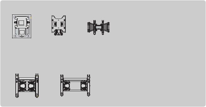
Wall Mounting Bracket(Separate purchase)
RW120 |
RW230 |
|
(19/22LU50** |
(26LU50**/32LF25** |
|
/19/22LU40** |
/26/32LH20 |
/32LH30 |
/19/22LH20**) |
** |
** |
/32LH40**/32LH49** |
||
|
/32LH50**/32LH70**) |
|
AW-47LG30M
(32/37/42LF25** 32/37/42LH20** /32/37/42/47LH30** /32/37/42/47LH40** /32/37/42/47LH49** /32/37/42/47LH50** /32/37/42/47LH70**)
AW-50PG60MS AW-60PG60MS
(50PS70**/50PS80**) (60PS70**/60PS80**)
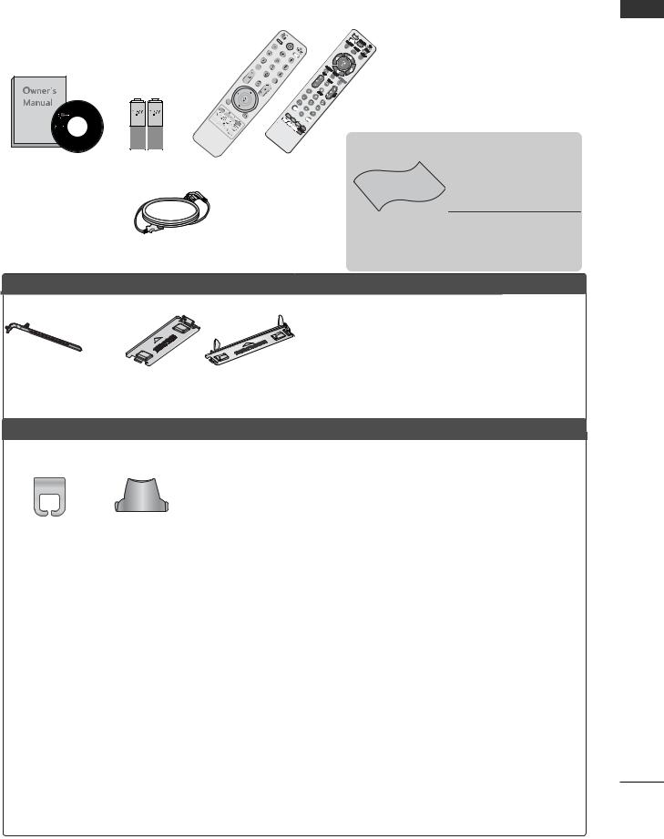
ACCESSORIES
Ensure that the following accessories are included with your TV. If an accessory is missing, please contact the dealer where you purchased the TV.
■ Image shown may differ from your
LIST
MUT
|
MENU |
|
Q. |
|
R |
MENU |
|
N/ |
INFO |
|
ETUR |
i |
IT |
|
|
|
EX |
|
GUIDE |
MARK |
|
|
|
|
|
FAV |
item is not included for all models.
Owner’s Manual |
Batteries |
Remote Control |
Ferrite Core |
|
(This item is not included for |
Power Cord |
all models.) |
PLASMA TV models
Polishing Cloth Polishing cloth for use on the screen.
*Lightly wipe any stains or fingerprints on the surface of the TV with the polishing cloth.
Do not use excessive force. This may cause scratching or discolouration.
x 2 |
or |
|
|
|
x 4 |
Cable Holder |
Protection cover |
Bolts for stand assembly |
Cable management clip |
(Refer to p.23) |
(Refer to p.24) |
(Refer to p.18) |
(Refer to p.23) |
LCD TV models |
|
|
|
|
|
|
|
|
|
|
|
|
|
|
Cable management clip |
1-screw for stand fixing |
|
|
|
|
|
|
|
Cable Holder |
|
|
|
||||
|
|
|
|
|
|
|
|
|
|||||
|
|
|
|
|
|
|
|
|
|||||
|
|
|
|
|
|
|
|
(Only 26LU50**, 32/37/42LF25**, |
|
||||
|
|
|
|
|
|
(Only 19/22LU40**, |
|
|
(Only 19/22LH20**) |
|
|||
|
|
|
|
|
|
|
|
26/32/37/42LH20 , 32/37/42LH30 , |
|||||
Cablemanagementclip |
Stand rear cover |
|
|
|
|
|
|
** |
** |
||||
19/22/26LU50**) |
|
|
(Refer to p.22) |
32/37/42LH40**, 32/37/42LH49**, |
|||||||||
(Only32/37/42/47LH70**) |
(Only 37/42/47LH70 ) |
(Refer to p.22) |
|
|
|
32/37/42LH50**, 32/37LH70**) |
|
||||||
(Refer to p.23) |
** |
|
|
|
|
|
|
|
(Refer to p.20) |
|
|||
|
(Refer to p.21) |
|
|
|
|
|
|
|
|||||
|
|
|
|
|
|
|
|
|
|
||||
Bolts for stand assembly
x 4 |
x 4 |
|
(Only32/37/42LF25**, 26/32/37/42LH20**, (Only 32/37/42/47LH30***, 32/37/42 32/37/42/47LH40***, LF25**)
32/37/42/47LH49**, 32/37/42/47LH50**)
or
Protection Cover
(Except for 19/22LU40**, 19/22/26LU50**)
(Refer to p.24)
(Refer to p. 17~19) |
|
|
|
|
|
||
x 2 |
x 3 |
|
|
x 8 |
|
|
|
|
|
|
|
|
|
||
|
|
|
x 7 |
x 8 |
x 3 |
x 4 |
|
(Only |
(Only |
M4x20 |
M4x20 |
M4x16 |
M4x20 |
M4x16 |
|
19/22LU40**, 26LU50**) |
|||||||
(Only 32LH70**) (Only 37LH70**) (Only 47LH70**) |
(Only 42LH70**) |
||||||
19/22LU50**) |
|
||||||
Protective Bracket |
USB extension cable |
and Bolt for Power Cord |
(Only 32/37/42/47LH70**) |
(Only 32/37/42/47LH70**) |
Make sure to use the provided |
(Refer to p.23) |
USB extension cable, Which is |
|
specially designed for a slim fit. |
ACCESSORIES
1
CONTENTS
ACCESSORIES . . . . . . . . . . . . . . . . . . . . . . . . . . . . . . . . . . . . . . . . . . . . 1
|
PREPARATION |
|
CONTENTS |
Detaching stand........................................................ |
19 |
|
Front Panel Controls..................................................... |
4 |
|
Back Panel Information............................................... |
11 |
|
Stand Installation......................................................... |
17 |
|
Attaching the TV to a desk ..................................... |
20 |
|
Desktop Pedestal Installation............................... |
20 |
|
Positioning your display ........................................ |
20 |
|
Kensington Security System ................................. |
20 |
|
Careful installation advice ..................................... |
21 |
|
Swivel Stand .................................................................. |
21 |
|
To use the stand rear cover .................................................. |
21 |
|
Back Cover for Wire Arrangement.......................... |
22 |
|
Not Using the desk-type stand ................................ |
24 |
|
Wall Mount: Horizontal Installation........................ |
25 |
|
Antenna Connection .................................................. |
26 |
|
EXTERNAL EQUIPMENT SETUP |
|
|
HD Receiver Setup...................................................... |
27 |
|
DVD Setup .................................................................... |
29 |
|
VCR Setup..................................................................... |
32 |
|
Insertion of CI Module .............................................. |
34 |
|
Digital Audio Out Setup ........................................... |
35 |
|
Headphone Setup....................................................... |
35 |
|
Other A/V Source Setup .......................................... |
36 |
|
Usb Setup...................................................................... |
37 |
|
PC Setup........................................................................ |
38 |
|
- Screen Setup for PC Mode................................ |
42 |
Manual Programme Tuning (In Digital Mode)..... |
55 |
Manual Programme Tuning (In Analogue Mode)... |
56 |
Programme Edit ........................................................... |
58 |
Booster(In Digital Mode)........................................... |
60 |
Software Update.......................................................... |
61 |
Diagnostics ................................................................... |
62 |
CI Information.............................................................. |
63 |
Selecting the Programme List.................................. |
64 |
Favourite Programme Setup...................................... |
65 |
Input List........................................................................ |
66 |
Input Label .................................................................... |
67 |
Simple manual .............................................................. |
68 |
................................................................. |
69 |
AV Mode........................................................................ |
72 |
Initializing (Reset to original factory settings) ..... |
73 |
TO USE A BLUETOOTH |
|
Precautions when using the Bluetooth ................. |
74 |
Setting the Bluetooth................................................. |
75 |
Set TV PIN...................................................................... |
76 |
Bluetooth headset |
|
- Connecting a new Bluetooth headset ............. |
77 |
- Connecting to Bluetooth headset already |
|
registered ................................................................. |
77 |
- Disconnecting the Bluetooth headset during use.... |
78 |
- When requesting to connect to TV from the |
|
Bluetooth headset.................................................... |
78 |
Managing Registered Bluetooth device ................ |
79 |
My Bluetooth Information......................................... |
80 |
Receiving Photos from external Bluetooth device ......... |
81 |
Listening to the Musics from external Bluetooth device...... |
81 |
WATCHING TV / PROGRAMME CONTROL
Remote Control Key Functions ............................... |
46 |
Turning on the TV....................................................... |
50 |
Programme Selection ................................................ |
50 |
Volume Adjustment ................................................... |
50 |
Quick Menu ................................................................. |
51 |
On-Screen Menus Selection and Adjustment..... |
52 |
Auto Programme Tuning............................................ |
53 |
TO USE A USB DEVICE |
|
When connecting the a USB device ...................... |
82 |
Photo List ...................................................................... |
83 |
Music List........................................................................ |
87 |
Movie List ....................................................................... |
90 |
DivX Registration Code.............................................. |
94 |
Deactivation................................................................... |
95 |
2

EPG (ELECTRONIC PROGRAMME |
|
GUIDE) (IN DIGITAL MODE) |
|
Switch on/off EPG...................................................... |
96 |
Select a Programme.................................................... |
96 |
Button Function in NOW/NEXT Guide Mode....... |
96 |
Button Function in 8 Day Guide Mode.................. |
97 |
Button Function in Date Change Mode................ |
97 |
Button Function in Extended Description Box......... |
98 |
Button Function in Record/Remind Setting Mode......... |
98 |
Button Function in Schedule List Mode ............... |
98 |
PICTURE CONTROL |
|
Picture Size (Aspect Ratio) Control ...................... |
99 |
Picture Wizard.............................................................. |
101 |
Energy Saving .............................................................. |
102 |
Preset Picture Settings |
|
- Picture Mode-Preset.......................................... |
103 |
Manual Picture Adjustment |
|
- Picture Mode-User option .............................. |
104 |
Picture Improvement Technology......................... |
105 |
Expert Picture Control............................................. |
106 |
Picture Reset .............................................................. |
109 |
Power Indicator ............................................................ |
110 |
Image Sticking Minimization (ISM) Method....... |
111 |
Demo Mode................................................................. |
112 |
Mode Setting................................................................ |
113 |
SOUND & LANGUAGE CONTROL |
|
Auto Volume Leveler.................................................. |
114 |
Clear Voice II................................................................. |
115 |
Preset Sound Settings - Sound Mode.................. |
116 |
Sound Setting Adjustment -User Mode ............... |
117 |
SRS TruSurround XT................................................. |
117 |
Balance.......................................................................... |
118 |
TV Speakers On/ Off Setup..................................... |
119 |
Selecting Digital Audio Out .................................... |
120 |
Audio Reset .................................................................. |
121 |
Audio Description (In Digital Mode only)........... |
122 |
I/II |
|
- Stereo/Dual Reception (In Analogue Mode |
|
Only)......................................................................... |
123 |
- NICAM Reception (In Analogue Mode Only).... |
124 |
- Speaker Sound Output Selection.................. |
124 |
On-Screen Menu Language/Country Selection.... |
125 |
Language Selection (In Digital Mode only)....... |
126 |
TIME SETTING |
|
Clock Setup ................................................................ |
127 |
Auto On/ Off Time Setting .................................... |
128 |
Sleep Timer Setting .................................................. |
129 |
PARENTAL CONTROL / RATINGS |
|
Set Password & Lock System................................. |
130 |
Block Programme....................................................... |
131 |
Parental Control (In Digital Mode only)............. |
132 |
External Input Blocking ............................................. |
133 |
Key Lock....................................................................... |
134 |
TELETEXT |
|
Switch on/off.............................................................. |
135 |
SIMPLE Text ................................................................ |
135 |
TOP Text...................................................................... |
135 |
FASTEXT...................................................................... |
136 |
Special Teletext Functions ...................................... |
136 |
DIGITAL TELETEXT |
|
Teletext within Digital Service................................ |
137 |
Teletext in Digital Service........................................ |
137 |
APPENDIX |
|
Troubleshooting......................................................... |
138 |
Maintenance .............................................................. |
140 |
Product Specifications ............................................. |
141 |
IR Codes ...................................................................... |
150 |
External Control Device Setup .............................. |
152 |
CONTENTS
3

PREPARATION
PREPARATION
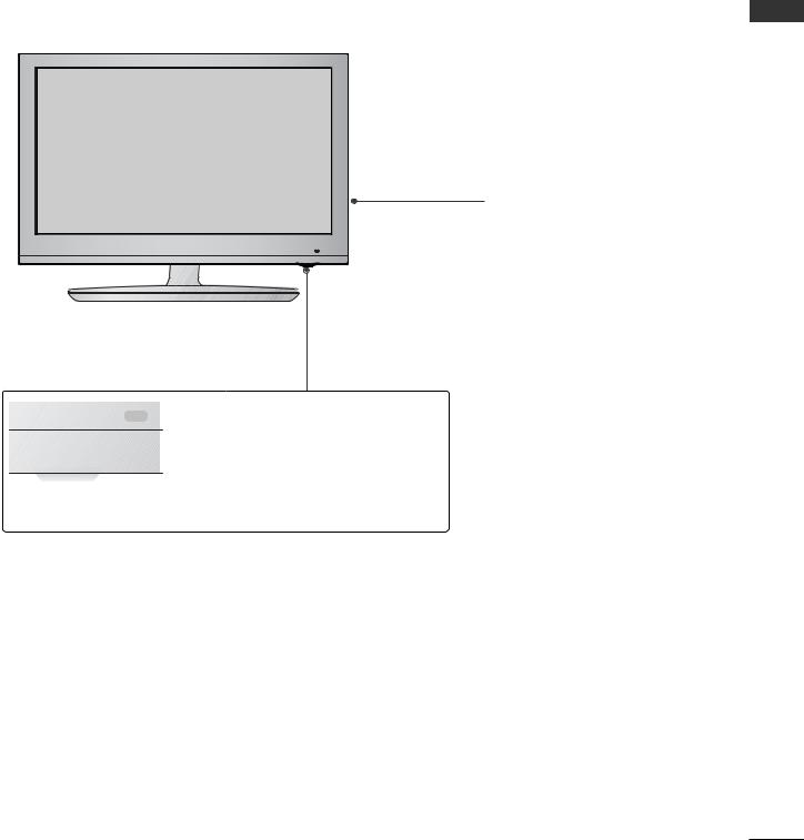
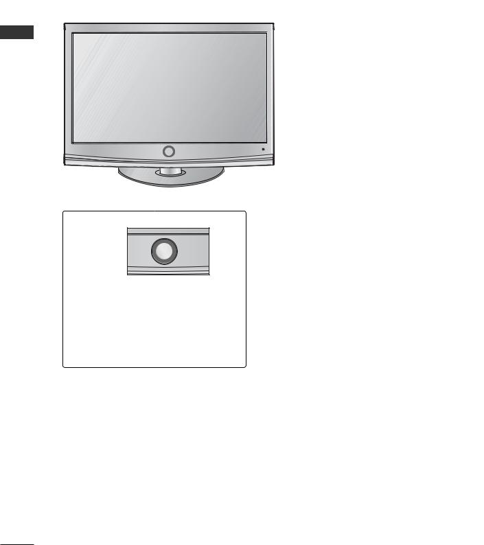
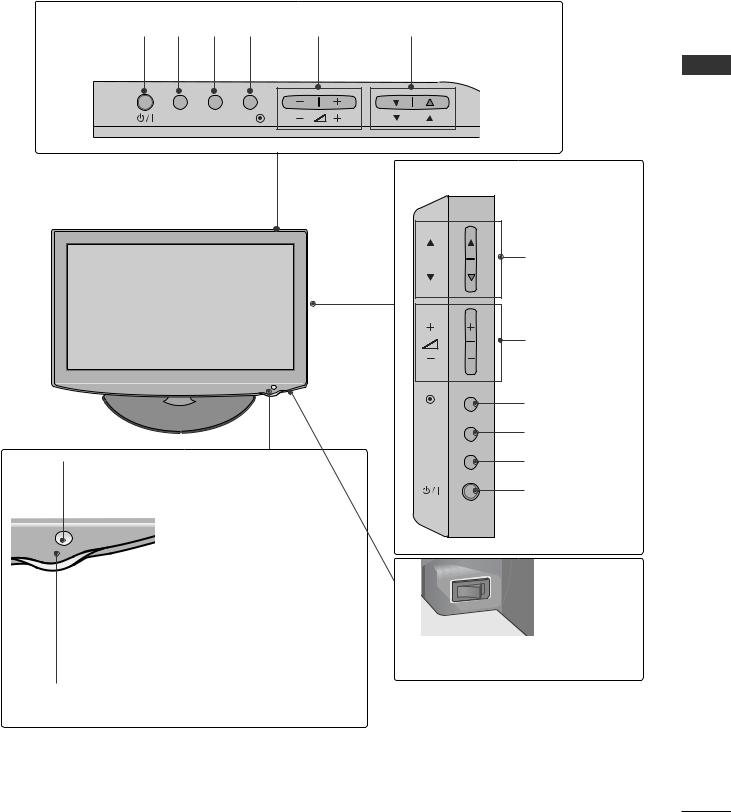
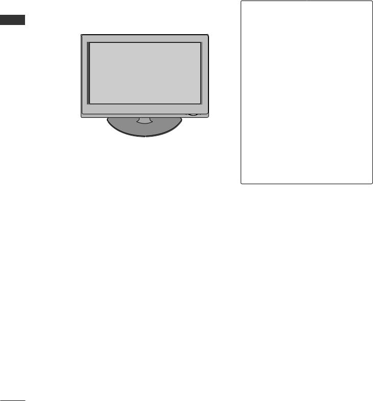
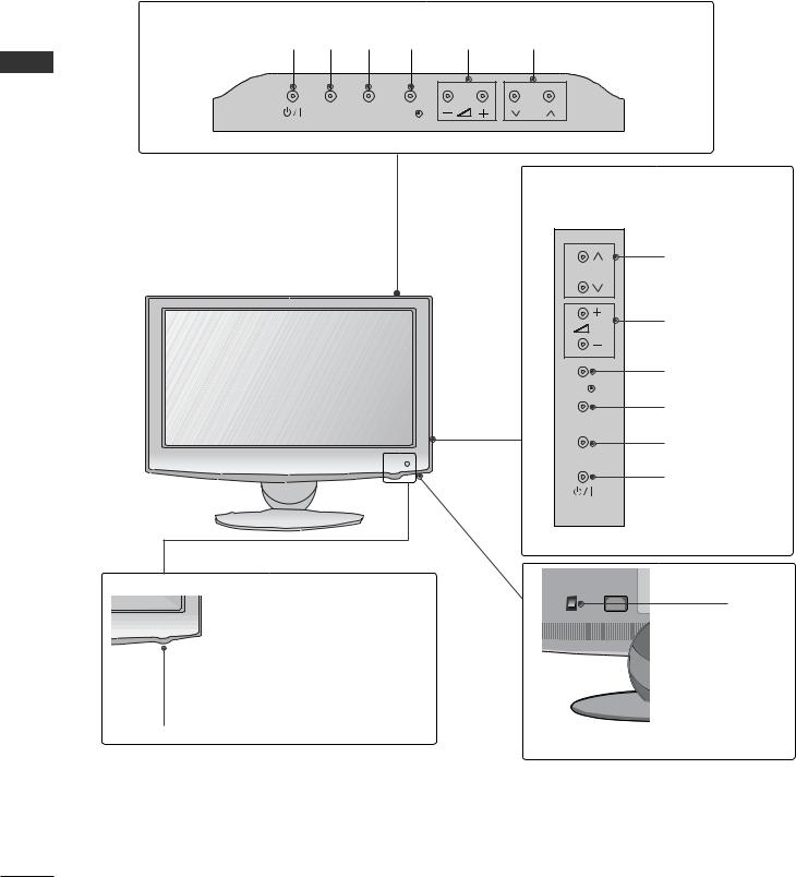
FRONT PANEL CONTROLS
■ Image shown may differ from your TV.
Plasma TV Models
 CAUTION
G When the TV cannot be turned on with the remote control, press the main power button on the TV. (When the power is turned off with the main power button on the TV, it will not be turned on with the remote control).
GDo not step on the glass stand or subject it to any impact.
GIt may break, causing possible injury from fragments of glass, or the TV may fall.
GDo not drag the TV. The floor or the product may be damaged.
50/60PS70**
Intelligent Sensor
Adjusts picture according to the surrounding conditions
Remote Control Sensor
 Power/Standby Indicator
• Illuminates red in standby mode.
• The LED is off while the TV remains on.
 PROGRAMME


 VOLUME
OK

 MENU
MENU

 INPUT
INPUT

 POWER
POWER
4
50/60PS80** |
|
|
PROGRAMME |
|
VOLUME |
Intelligent Sensor |
OK |
Adjusts picture according to |
|
the surrounding conditions |
|

 MENU
MENU

 INPUT
INPUT
Remote Control Sensor
 POWER
POWER
 Power/Standby Indicator
•Illuminates red in standby mode.
•The LED is off while the TV remains on.
PREPARATION
5
PREPARATION
LCD TV Models : 32/37/42/47LH70**
|
|
PROGRAMME |
PREPARATION |
|
P |
|
VOLUME |
|
|
|
|
|
Intelligent Sensor |
OK |
|
OK |
|
|
Adjusts picture according to |
|
|
|
|
|
the surrounding conditions |
|
|
Remote Control Sensor |
MENU |
|
MENU |
|
|
|
|
|
Moving LED |
INPUT |
|
|
|
|
|
INPUT |
POWER(Touch Sensor)
Power/Standby Indicator
•Illuminates red in standby mode.
•Illuminates whitish when the TV is switched on.
Note: You can adjust Power Indicator in the
OPTION menu.
Main Power Switch
6
LCD TV Models : 19/22/26/32/37/42LH20**, 32/37/42/47LH30**
(Only 19/22/26LH20**) |
|
|
|
|
|
|
POWER INPUT MENU |
OK |
VOLUME |
PROGRAMME |
PREPARATION |
||
INPUT MENU |
OK |
|
|
(Only 32/37/42LH20**, 32/37/42/47LH30**) |
||
|
|
P |
|
|
||
|
|
|
|
P |
PROGRAMME |
|
|
|
|
|
|
VOLUME |
|
|
|
|
|
OK |
OK |
|
|
|
|
|
|
|
|
|
|
|
|
MENU |
MENU |
|
|
|
|
|
|
|
|
Remote Control Sensor |
|
|
|
INPUT |
INPUT |
|
|
|
|
|
|
|
|
|
|
|
|
|
POWER |
|
|
|
|
|
|
|
|
Power/Standby Indicator |
|
|
|
|
|
|
Illuminates red in standby mode. |
|
|
Main Power Switch |
|
||
Illuminates blue when the TV is switched on. |
|
|
|
|
||
7
PREPARATION
LCD TV Models : 32/37/42/47LH40**, 32/37/42/47LH49**, 32/37/42/47LH50**
PREPARATION
Remote Control Sensor Intelligent Sensor
 Adjusts picture according to
 the surrounding conditions.
Power/Standby Indicator
•Illuminates red in standby mode.
•Illuminates blue when the TV is switched on.
 PROGRAMME
P
 VOLUME
OK
OK 
MENU
MENU
INPUT
INPUT
POWER
OFF  ON
ON
Main Power Switch
8
LCD TV Models : 19/22LU40**
POWER INPUT MENU OK |
VOLUME PROGRAMME |
INPUT MENU OK |
P |
Main Power Switch
Remote Control Sensor
Power/Standby Indicator
• illuminates red in standby mode.
• illuminates white when the TV is switched on.
LCD TV Models : 32/37/42LF25**
POWER
Remote Control Sensor
Power/Standby Indicator
•illuminates red in standby mode.
•illuminates blue when the TV is switched on.
P |
PROGRAMME |
+
 VOLUME
-
OK
OK
MENU
MENU
INPUT
INPUT
PREPARATION
9
PREPARATION
PREPARATION
LCD TV Models : 19/22/26LU50**
(Only 19/22LU50**)
POWER INPUT MENU OK |
VOLUME PROGRAMME |
INPUT MENU OK |
P |


 Remote Control Sensor
Power/Standby Indicator
Illuminates red in standby mode.
Illuminates white when the TV is switched on.
(Only 26LU50**) |
|
|
PROGRAMME |
P |
|
|
VOLUME |
|
OK |
OK |
|
|
MENU |
MENU |
|
|
INPUT |
INPUT |
|
|
POWER |
|
Main |
|
|
|
Power |
|
|
|
Switch |
10
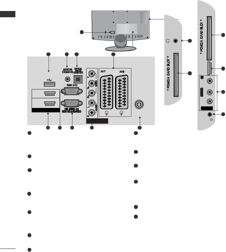
BACK PANEL INFORMATION
A Image shown may differ from your TV.
Plasma TV Models
|
|
|
10 |
1 |
|
|
|
|
|
|
11 |
2 |
3 |
4 |
5 |
|
|||
|
|
|
2 |
|
|
|
12 |
|
|
|
|
|
|
|
|
|
|
|
|
|
|
|
|
|
|
|
|
|
|
|
|
|
|
|
|
|
|
|
|
|
|
|
|
|
|
|
|
|
|
|
|
|
|
|
|
|
|
|
|
|
|
|
|
|
|
|
|
|
|
|
|
|
|
|
|
|
|
|
|
|
|
|
|
|
|
|
|
|
|
|
|
|
|
|
|
|
|
|
|
|
|
|
|
|
|
|
|
|
|
|
|
|
|
|
|
|
|
|
|
|
|
|
|
|
|
|
|
|
|
|
|
|
|
6 |
|
|
|
|
|
|
|
|
|
|
|
|
|
|
|
|
|
|
|
|
|
|
|
|
||||
|
|
|
|
7 |
|
|
|
|
|
|
8 |
|
|
|
|
|
|
|
|
|||||||||||
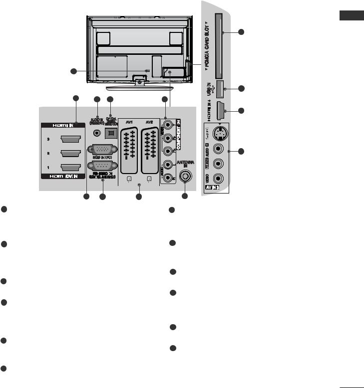
1Power Cord Socket
This TV operates on an AC power. The voltage is indicated on the Specifications page. Never attempt to operate the TV on DC power.
2HDMI/DVI IN Input
Connect an HDMI signal to HDMI IN.
Or DVI(VIDEO)signal to HDMI/DVI port with DVI to HDMI cable.
3RGB/DVI Audio Input
Connect the audio from a PC or DTV.
4OPTICAL DIGITAL AUDIO OUT
Connect digital audio to various types of equipment. Connect to a Digital Audio Component.
9
7RS-232C IN (CONTROL & SERVICE) PORT
Connect to the RS-232C port on a PC. This port is used for Service or Hotel mode.
8Euro Scart Socket (AV1/AV2)
Connect scart socket input or output from an external device to these jacks.
9Antenna Input
Connect antenna or cable to this jack.
10PCMCIA (Personal Computer Memory Card International Association) Card Slot
Insert the CI Module to PCMCIA CARD SLOT. (This feature is not available in all countries.)
Use an Optical audio cable.
5Component Input
Connect a component video/audio device to these jacks.
6RGB IN Input
Connect the output from a PC.
11USB Input
Connect USB storage device to this jack.
12S-Video Input
Connect S-Video out from an S-VIDEO device.
Audio/Video Input
Connect audio/video output from an external device to these jacks.
PREPARATION
11

PREPARATION
LCD TV Models : 32/37/42/47LH70**
PREPARATION
2 |
|
|
|
|
12 |
|
|
|
|
|
|
3 |
|
|
|
|
|
4 |
5 |
6 |
1 |
|
7 |
|
|
||||
|
8 |
|
9 |
10 |
11 |
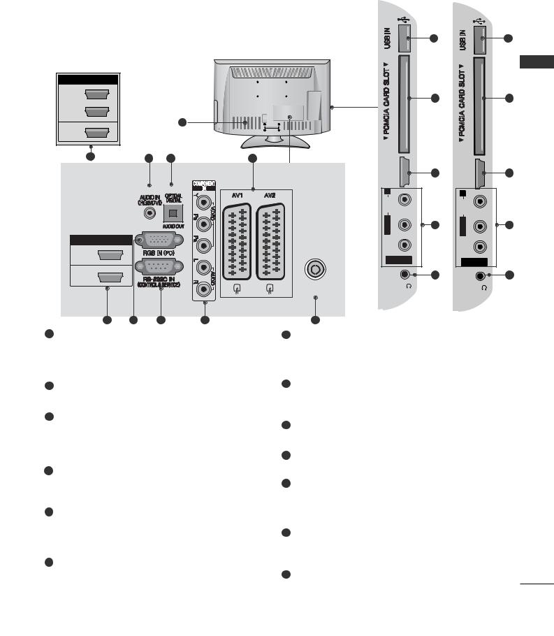
1Power Cord Socket
This TV operates on an AC power. The voltage is indicated on the Specifications page. Never attempt to operate the TV on DC power.
2USB Input
Connect USB storage device to this jack.
3HDMI/DVI IN Input
Connect an HDMI signal to HDMI IN.
Or DVI(VIDEO)signal to HDMI/DVI port with DVI to HDMI cable.
4S-Video Input
Connect S-Video out from an S-VIDEO device.
Audio/Video Input
Connect audio/video output from an external device to these jacks.
5RGB IN Input
Connect the output from a PC.
RGB/DVI Audio Input
Connect the audio from a PC or DTV.
6RS-232C IN (CONTROL & SERVICE) PORT
Connect to the RS-232C port on a PC. This port is used for Service or Hotel mode.
7Antenna Input
Connect antenna or cable to this jack.
8Component Input
Connect a component video/audio device to these jacks.
9OPTICAL DIGITAL AUDIO OUT
Connect digital audio to various types of equipment. Connect to a Digital Audio Component.
Use an Optical audio cable.
10Euro Scart Socket (AV1/AV2)
Connect scart socket input or output from an external device to these jacks.
11Headphone Socket
Plug the headphone into the headphone socket.
12PCMCIA (Personal Computer Memory Card International Association) Card Slot
Insert the CI Module to PCMCIA CARD SLOT. (This feature is not available in all countries.)
12
LCD TV Models : 32/37/42/47LH40**, 32/37/42/47LH49**, 32/37/42/47LH50**
(Only32/37/42/47LH50**/
32/37/42/47LH49**)
|
|
|
|
|
|
10 |
|
10 |
|
(Only32/37/42/47LH50**/ |
|
|
|
|
|
|
|
|
|
32/37/42/47LH49**) |
|
|
|
|
|
|
|
|
|
HDMI / DVI IN |
|
|
|
|
|
|
|
|
PREPARATION |
3 |
|
|
|
|
|
11 |
|
11 |
|
|
|
|
|
|
|
|
|||
|
|
|
|
|
|
|
|
||
2 |
|
|
|
|
|
|
|
|
|
|
|
|
|
1 |
|
|
|
|
|
1(DVI) |
|
|
|
|
|
|
|
|
|
5 |
|
2 |
3 |
4 |
HDMI |
IN3 |
HDMI |
IN4 |
|
|
|
|
|
|
|
||||
|
|
|
|
|
|
5 |
|
5 |
|
|
|
|
|
|
R |
|
R |
|
|
|
|
|
|
(RGB) |
AUDIO |
|
AUDIO |
|
|
|
|
|
|
|
|
|
|
|
|
|
|
|
|
|
M/LONO |
12 |
L/MONO |
12 |
|
|
|
|
|
|
|
|
|
||
HDMI / DVI IN |
|
|
|
|
VIDEO |
|
VIDEO |
|
|
2 |
|
|
|
|
|
|
|
||
|
|
|
|
|
AV IN 3 |
|
AV IN 3 |
|
|
|
|
|
|
|
|
|
|
||
|
|
|
|
|
|
|
|
|
|
1(DVI) |
|
|
|
|
|
13 |
|
13 |
|
|
|
|
|
|
ANTENNA IN |
H/P |
|
H/P |
|
|
|
|
|
|
|
|
|
||
|
|
|
|
|
|
|
|
|
|
5 |
6 |
|
7 |
8 |
9 |
|
|
|
|
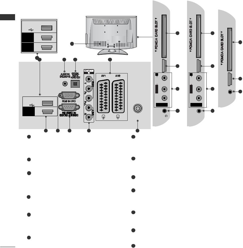
1 Power Cord Socket |
|
|
|
7 RS-232C IN (CONTROL & SERVICE) PORT |
|
||||
This TV operates on an AC power. The voltage is |
Connect to the RS-232C port on a PC. |
|
|
|
|||||
indicated on the Specifications page. Never |
This port is used for Service or Hotel mode. |
|
|||||||
attempt to operate the TV on DC power. |
|
|
|
|
|
||||
2RGB/DVI Audio Input
Connect the audio from a PC or DTV.
3OPTICAL DIGITAL AUDIO OUT
Connect digital audio to various types of equipment. Connect to a Digital Audio Component.
Use an Optical audio cable.
4Euro Scart Socket (AV1/AV2)
Connect scart socket input or output from an external device to these jacks.
5HDMI/DVI IN Input
Connect an HDMI signal to HDMI IN. Or DVI (VIDEO) signal to HDMI/DVI port with DVI to HDMI cable.
6RGB IN Input
Connect the output from a PC.
8Component Input
Connect a component video/audio device to these jacks.
9Antenna Input
Connect antenna or cable to this jack.
10USB Input
Connect USB storage device to this jack.
11PCMCIA (Personal Computer Memory Card International Association) Card Slot
Insert the CI Module to PCMCIA CARD SLOT. (This feature is not available in all countries.)
12Audio/Video Input
Connect audio/video output from an external device to these jacks.
13Headphone Socket
Plug the headphone into the headphone socket.
13
|
PREPARATION |
|
|
|
|
|
|
||
|
LCD TV Models : 32/37/42LF25**, 26/32/37/42LH20**, |
|
|
|
|||||
|
32/37/42/47LH30** |
(Only32/37/42/47LH30 |
) |
(Only26/32/37/42LH20 |
) |
||||
|
|
|
|
|
|
** |
** |
||
|
|
|
|
|
|
|
|
(Only32/37/42LF25**) |
|
|
(Only32/37/42/47LH30**) |
|
|
|
|
|
|
|
|
PREPARATION |
USB IN |
|
|
|
|
|
|
|
|
SERVICE ONLY |
|
|
|
|
|
|
|
||
|
|
|
|
|
10 |
|
10 |
|
|
HDMI |
2 |
|
|
|
|
|
|
|
|
HDMI |
|
1 |
|
|
|
|
|
10 |
|
1 |
|
|
|
|
|
|
|||
|
|
|
|
|
|
|
|||
/ DVI IN |
|
|
|
|
|
|
|
||
|
|
|
|
|
|
|
|
|
|
|
|
5 |
2 |
3 |
4 |
|
|
|
|
|
|
|
|
|
|
|
|||
|
|
|
|
|
HDMI |
5 |
|
5 |
|
|
|
|
|
|
IN3 |
|
HDMI IN2 |
|
|
USB IN
SERVICE ONLY
HDMI |
1 |
/ DVI IN |
(RGB)
VIDEO L/MONO AUDIO R
AV IN 3
H/P
ANTENNA IN
11
12
VIDEO L/MONO AUDIO R
AV IN 3
H/P
IN 2
HDMI
11
H/P
12
5
12
5 |
6 |
7 |
8 |
9 |
1Power Cord Socket
This TV operates on an AC power. The voltage is indicated on the Specifications page. Never attempt to operate the TV on DC power.
2RGB/DVI Audio Input
Connect the audio from a PC or DTV.
3OPTICAL DIGITAL AUDIO OUT
Connect digital audio to various types of equipment. Connect to a Digital Audio Component.
Use an Optical audio cable.
4Euro Scart Socket (AV1/AV2)
Connect scart socket input or output from an external device to these jacks.
5HDMI/DVI IN Input
Connect an HDMI signal to HDMI IN. Or DVI (VIDEO) signal to HDMI/DVI port with DVI to HDMI cable.
6RGB IN Input
Connect the output from a PC.
7RS-232C IN (CONTROL & SERVICE) PORT
Connect to the RS-232C port on a PC. This port is used for Service or Hotel mode.
8Component Input
Connect a component video/audio device to these jacks.
9Antenna Input
Connect antenna or cable to this jack.
10PCMCIA (Personal Computer Memory Card International Association) Card Slot
Insert the CI Module to PCMCIA CARD SLOT. (This feature is not available in all countries.)
11Audio/Video Input
Connect audio/video output from an external device to these jacks.
12Headphone Socket
Plug the headphone into the headphone socket.
13SERVICE ONLY PORT
14
LCD TV Models : 19/22LH20**
11
1
12 |
|
2 |
3 |
|
4 |
|
|
|
|
|
10 |
|
|
|
COMPONENTIN |
(RGB) |
H/P |
USB IN |
|
|
|
||
|
|
|
|
|
|
SERVICE ONLY |
|
|
|
|
|
|
|
RGB IN (PC) |
|
|
|
HDMI / DVI IN |
|
|
|
|
|
|
|
|
|
|
ANTENNA IN |
5 |
6 |
7 |
8 |
|
9 |
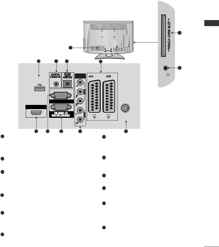
1 Power Cord Socket |
|
|
|
|
7 RS-232C IN (CONTROL & SERVICE) PORT |
This TV operates on an AC power. The voltage is |
|
Connect to the RS-232C port on a PC. |
|||
indicated on the Specifications page. Never |
|
This port is used for Service or Hotel mode. |
|||
attempt to operate the TV on DC power. |
|
|
|||
2RGB/DVI Audio Input
Connect the audio from a PC or DTV.
3OPTICAL DIGITAL AUDIO OUT
Connect digital audio to various types of equipment. Connect to a Digital Audio Component.
Use an Optical audio cable.
4Euro Scart Socket (AV1/AV2)
Connect scart socket input or output from an external device to these jacks.
5HDMI/DVI IN Input
Connect an HDMI signal to HDMI IN. Or DVI (VIDEO) signal to HDMI/DVI port with DVI to HDMI cable.
6RGB IN Input
Connect the output from a PC.
8Component Input
Connect a component video/audio device to these jacks.
9Antenna Input
Connect antenna or cable to this jack.
10Headphone Socket
Plug the headphone into the headphone socket.
11PCMCIA (Personal Computer Memory Card International Association) Card Slot
Insert the CI Module to PCMCIA CARD SLOT. (This feature is not available in all countries.)
12SERVICE ONLY PORT
PREPARATION
15
PREPARATION
PREPARATION
16
(Only 26LU50**)
LCD TV Models : 19/22LU40**, 19/22/26LU50**
|
|
|
|
|
|
|
|
|
|
|
|
1 |
|
|
|
|
|
|
|
|
|
|
11 |
|
|
|
|
|
|
|
|
|
|
|
|
|
H/P |
10 |
|
12 |
|
2 |
3 |
|
4 |
|
|
|
|
|
|
|
|
HDMI |
IN 3 |
|
|
|
|
(RGB) |
|
|
5 |
USB IN |
|
|
|
|
11 |
|
|
|
|
|
|
|
|
||
SERVICE ONLY |
|
|
|
|
|
R |
|
|
|
|
|
|
|
AUDIO |
|
2 |
|
|
|
|
|
L/MONO |
13 |
|
|
|
|
|
|
||
|
|
|
|
|
|
|
|
1(DVI) |
|
|
|
|
|
VIDEO |
|
HDMI / DVI IN |
|
|
|
|
|
|
AV IN 3 |
|
|
|
|
|
|
|
|
|
|
|
|
|
ANTENNA IN |
|
10 |
|
|
|
|
COMPONENT IN |
|
|
H/P |
|
|
|
|
|
|
|
|
5 |
6 |
|
7 |
8 |
9 |
|
|
1Power Cord Socket
This TV operates on an AC power. The voltage is indicated on the Specifications page. Never attempt to operate the TV on DC power.
2RGB/DVI Audio Input
Connect the audio from a PC or DTV.
3OPTICAL DIGITAL AUDIO OUT
Connect digital audio to various types of equipment. Connect to a Digital Audio Component.
Use an Optical audio cable.
4Euro Scart Socket (AV1/AV2)
Connect scart socket input or output from an external device to these jacks.
5HDMI/DVI IN Input
Connect an HDMI signal to HDMI IN. Or DVI (VIDEO) signal to HDMI/DVI port with DVI to HDMI cable.
6RGB Input
Connect the output from a PC.
7RS-232C IN (CONTROL & SERVICE) PORT
Connect to the RS-232C port on a PC. This port is used for Service or Hotel mode.
8Component Input
Connect a component video/audio device to these jacks.
9Antenna Input
Connect antenna or cable to this jack.
10Headphone Socket
Plug the headphone into the headphone socket.
11PCMCIA (Personal Computer Memory Card International Association) Card Slot
Insert the CI Module to PCMCIA CARD SLOT. (This feature is not available in all countries.)
12SERVICE ONLY PORT
13Audio/Video Input
Connect audio/video output from an external device to these jacks.
STAND INSTALLATION
■ Image shown may differ from your TV
When assembling the desk type stand, check whether the bolt is fully tightened. (If not tightened fully, the product can tilt forward after the product installation.) If you tighten the bolt with excessive force, the bolt can deviate from abrasion of the tightening part of the bolt.
Only 32/37/42/47LH70**
1Carefully place the TV screen side down on a cushioned surface to protect the screen from damage.
Only 26/32/37/42LH20**,
32/37/42/47LH30**, 32/37/42/47LH40**, 32/37/42/47LH49**, 32/37/42/47LH50**
1Carefully place the TV screen side down on a cushioned surface to protect the screen from damage.
2Assemble the parts of the Stand Body with the Stand Base of the TV.
32LH70** 47LH70** 37LH70**
M4x20 |
Stand Body |
M4x20 |
M4x16 |
 Stand Base
42LH70**
M4x20
Stand Body
Stand Base
2Assemble the TV as shown.
3Fix the 4 bolts securely using the holes in the back of the TV.
3Assemble the TV as shown.
PREPARATION
4Fix the 4 bolts securely using the holes in the back of the TV.
32/37LH70** |
42/47LH70** |
M4x20 |
M4x16 |
|
17

PREPARATION
PREPARATION
Only 19/22LH20** |
Only 50PS70**/50PS80** |
|
1 Carefully place the TV screen side down on a cushioned |
|
surface to protect the screen from damage. |
1Carefully place the TV screen side down on a cushioned surface to protect the screen from damage.
2 |
2 Assemble the TV as shown. |
Assemble the TV as shown. |
Cover Base
Only 19/22LU40**, 19/22/26LU50**
1Carefully place the TV screen side down on a cushioned surface to protect the screen from damage.
2Fix the 2 or 3 bolts securely using the holes in the back of the TV.
(Only 26LU50**)
3Fix the 4 bolts securely using the holes in the back of the TV.
make sure to distinguish and assemble the front and rear side of the stand correctly.
Front
18
Only 32/37/42LF25**
1Carefully place the TV screen side down on a cushioned surface to protect the screen from damage.
2Assemble the parts of the Stand Body with the Cover Base of the TV.
Stand Body
Cover Base
3Assemble the TV as shown.
DETACHING STAND
Only 19/22LU40**, 19/22/26LU50**
■ Image shown may differ from your TV. |
|
|
1 |
Carefully place the TV screen side down on a cush- |
PREPARATION |
|
ioned surface to protect the screen from damage. |
|
|
|
|
2Loose the bolts and then detach the stand from TV.
(Only 26LU50**)
3Loose the bolts from TV.
Detach the Cover Base from T V.
Cover Base
(Only 26LU50**)
4 |
Fix the 4 bolts securely using the holes in the |
4 Detach the Stand Body from T V. |
Stand Body |
||
|
back of the TV. |
|
19
PREPARATION
ATTACHING THE TV TO A DESK
(Only 26LU50**, 32/37/42LF25**, 26/32/37/42LH20**, 32/37/42LH30**, 32/37/42LH40**, 32/37/42LH49**, 32/37/42LH50**, 32/37LH70**)
■ Image shown may differ from your TV.
|
The TV must be attached to desk so it cannot be |
||
PREPARATION |
pulled in a forward/backward direction, potentially |
||
causing injury or damaging the product. Use only an |
|||
|
|||
|
attached screw. |
||
|
|
1-Screw |
|
|
|
(provided as parts of the product) |
|
|
|
Stand |
|
|
|
Desk |
|
|
! |
WARNING |
|
|
G To prevent TV from falling over, the TV should |
||
|
|
be securely attached to the floor/wall per |
|
|
|
installation instructions. Tipping, shaking, or |
|
rocking the machine may cause injury.
DESKTOPPEDESTALINSTALLATION
For adequate ventilation allow a clearance of 4” (10cm) all around the TV.
4 inches
4 inches
4 inches |
4 inches |
|
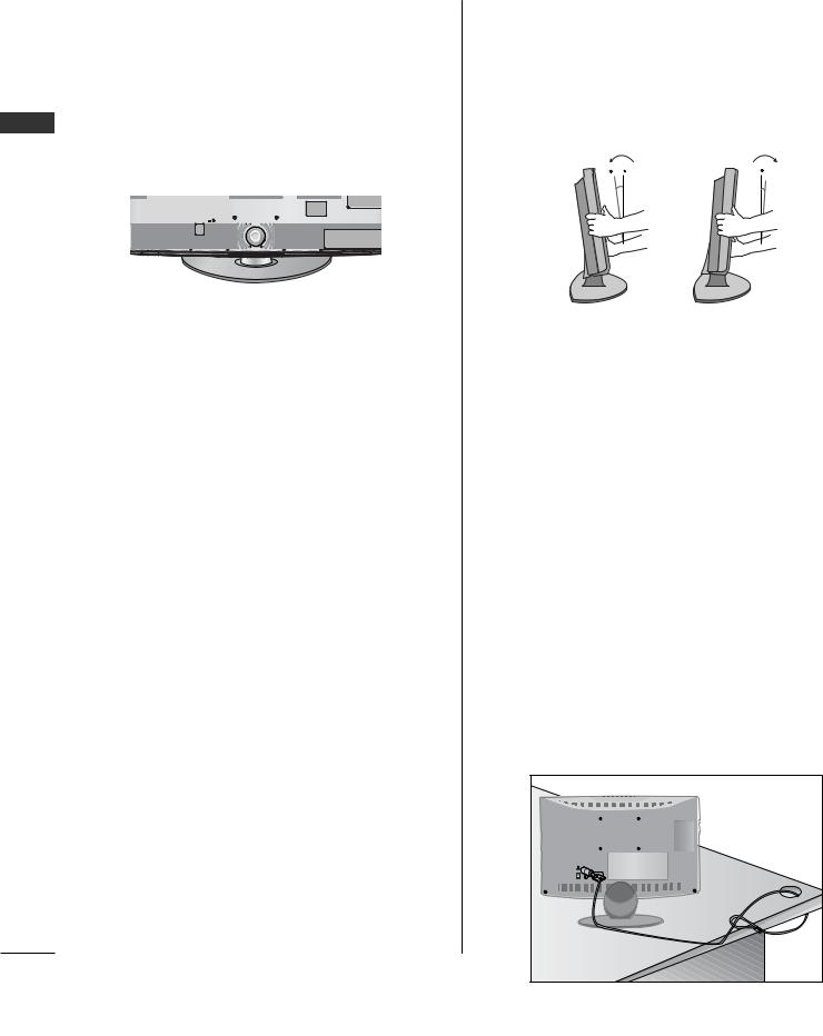
POSITIONING YOUR DISPLAY
(Only 19/22LH20**)
■Image shown may differ from your TV.
■Adjust the position of the panel in various ways for maximum comfort.
•Tilt range
12 |
0 |
0 |
3 |
KENSINGTONSECURITYSYSTEM
■This feature is not available for all models.
■Image shown may differ from your TV.
The TV is equipped with a Kensington Security System connector on the back panel. Connect the Kensington Security System cable as shown below.
For the detailed installation and use of the Kensington Security System, refer to the user’s guide provided with the Kensington Security System.
For further information, contact http://www.kensington.com, the internet homepage of the Kensington
company. Kensington sells security systems for expensive electronic equipment such as notebook PCs and LCD projectors.
NOTE
- The Kensington Security System is an optional accessory.
NOTES
a.If the TV feels cold to the touch, there may be a small “flicker” when it is turned on.
This is normal, there is nothing wrong with TV.
b.Some minute dot defects may be visible on the screen, appearing as tiny red, green, or blue spots. However, they have no adverse effect on the monitor's performance.
c.Avoid touching the LCD screen or holding your finger(s) against it for long periods of time.
Doing so may produce some temporary distortion
effects on the screen.
20
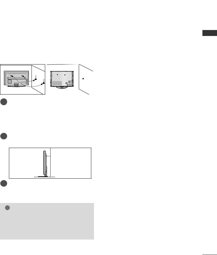
CAREFUL INSTALLATION ADVICE
A You should purchase necessary components to fix the TV safety and secure to the wall on the market.
A Position the TV close to the wall to avoid the possibility of it falling when pushed.
A The instructions shown below are a safer way to set up the TV, by fixing it to the wall, avoiding the possibility of it falling forwards if pulled. This will prevent the TV from falling forward and causing injury. This will also prevent the TV from damage. Ensure that children do not climb or hang from the TV.
1 |
2 |
1 |
2 |
1Use the eye-bolts or TV brackets/bolts to fix the product to the wall as shown in the picture.
(If your TV has bolts in the eyebolts, loosen then bolts.)
* Insert the eye-bolts or TV brackets/bolts and tighten them securely in the upper holes.
2Secure the wall brackets with the bolts on the wall. Match the height of the bracket that is mounted on the wall.
3
3Use a sturdy rope to tie the product for alignment. It is safer to tie the rope so it becomes horizontal between the wall and the product.
! NOTE
GWhen moving the TV undo the cords first.
GUse a platform or cabinet strong and large enough to support the size and weight of the TV.
GTo use the TV safely make sure that the height of the bracket on the wall and on the TV is the same.
SWIVEL STAND
(Except for 19/22LH20**, 19/22LU40**, 19/22/26LU50**)
■ Image shown may differ from your TV.
After installing the TV, you can adjust the TV set manually to the left or right direction by 20 degrees to suit your viewing position.
TO USE THE STAND REAR
COVER (Only 37/42/47LH70**)
■ Image shown may differ from your TV. Install the STAND REAR COVER as shown.
STAND REAR COVER
Grip the knob in your fingers and pull it.
PREPARATION
21
PREPARATION
PREPARATION
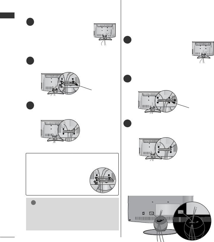
BACK COVER FOR WIRE ARRANGEMENT
■ Image shown may differ from your TV.
LCD TV Models : 19/22LH20**
1 Connect the cables as necessary.
To connect additional equipment, see the EXTERNAL EQUIPMENT SETUP section.
2 Install the CABLE MANAGEMENT CLIP as shown.
LCD TV Models : 32/37/42LF25**, 26/32/37/42LH20**, 32/37/42/47LH30**, 32/37/42/47LH40**, 32/37/42/47LH49**,
32/37/42/47LH50**
1 Connect the cables as necessary.
To connect additional equipment, see the EXTERNAL EQUIPMENT SETUP section.
CABLE MANAGEMENT CLIP |
3 Fit the CABLE MANAGEMENT CLIP as shown.
2Install the CABLE MANAGEMENT CLIP as shown.
CABLE MANAGEMENT CLIP |
3Fit the CABLE MANAGEMENT CLIP as shown.
How to remove the cable management
clip (LCD TV Models : 19/22LH20**)
Hold the CABLE MANAGEMENT CLIP with both hands and pull it backward.
! NOTE
G Do not use the CABLE MANAGEMENT CLIP to lift the TV.
-If the TV is dropped, you may be injured or the TV may be damaged.
LCD TV Models :
19/22LU40**, 19/22/26LU50**
After Connecting the cables as necessary, install CABLE HOLDER as shown and bundle the cables.
22
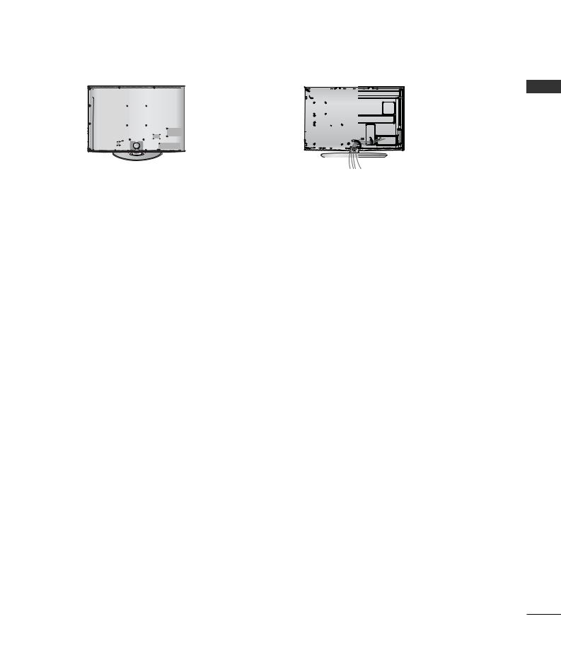
LCD TV Models : 32/37/42/47LH70**
Align the hole with the tab on the CABLE
1MANAGEMENT CLIP.
Turn the CABLE MANAGEMENT CLIP as shown.
Note : that excessive force might cause damage to the product when using Cable Management clip.
Plasma TV Models
1After Connecting the cables as necessary, install CABLE HOLDER as shown and bundle the cables.
To connect additional equipment, see the External equipment Setup section.
PREPARATION
CABLE HOLDER
2 Install the CABLE MANAGEMENT CLIP as
|
shown. |
|
CABLE MANAGEMENT CLIP |
2 |
Connect the cables as necessary. |
To connect additional equipment, see the |
|
|
External equipment Setup section. |
How to secure the power cable
(Only 32/37/42/47LH70**)
1Secure the power cable with the PROTECTIVE BRACKET and the bolt as shown. It will help prevent the power cable from being removed by accident.
Bolt
CABLE MANAGEMENT CLIP
How to remove the cable management clip
Hold the CABLE MANAGEMENT CLIP with both hands and pull it upward.
PROTECTIVE BRACKET
! NOTE
G Do not use the CABLE MANAGEMENT CLIP to lift the TV.
- If the TV is dropped, you may be injured or the TV may be damaged.
23
PREPARATION
PREPARATION
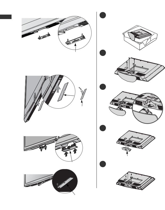
NOT USING THE DESK-TYPE STAND
(Except for 19/22LU40**, 19/22/26LU50**)
■ Image shown may differ |
|
When installing the wall- |
protection cover. |
Plasma TV models |
1 Carefully place the TV screen side down on a |
|
cushioned surface to protect the screen from |
|
damage. |
PROTECTION COVER |
2 Loose the bolts from TV. |
Insert the PROTECTION COVER into the TV until clicking sound.
LCD TV models
Only 32/37/42/47LH70**
3 Detach the stand from TV.
COVER
paper adhere it
Only 26/32/37/42LH20**, 32/37/42/47LH30**, 32/37/42/47LH40**, 32/37/42/47LH49**, 32/37/42/47LH50**
Insert the PROTECTION
COVER into the TV until
clicking sound. |
PROTECTION COVER |
|
Only 32/37/42LF25**
|
Insert the PROTECTION |
|
|
|
|
24 |
COVER into the TV until |
PROTECTION COVER |
clicking sound. |
|
|
|
|
4Insert the Protection Cover into the TV.
PROTECTION COVER
Fix the 4 bolts securely using the holes in the 5 back of the TV.
AThe TV can be installed in various ways such as on a wall, or on a desktop etc.
AThe TV is designed to be mounted horizontally.
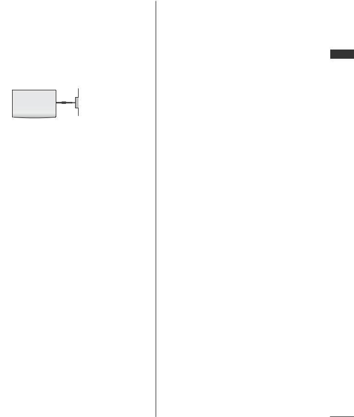
EARTHING
Ensure that you connect the earth wire to prevent possible electric shock. If grounding methods are not possible, have a qualified electrician install a separate circuit breaker.
Do not try to earth the TV by connecting it to telephone wires, lightening rods or gas pipes.
Power Supply
Circuit breaker
WALL MOUNT: HORIZONTAL INSTALLATION
A We recommend the use of a LG Brand wall mounting bracket when mounting the TV to a wall.
A We recommend that you purchase a wall mounting bracket which supports VESA standard.
A LG recommends that wall mounting be performed by a qualified professional installer.
! NOTE
GShould Install wall mount on a solid wall perpendicular to the floor.
GShould use a special wall mount, if you want to install it to ceiling or slanted wall.
GThe surface that wall mount is to be mounted on should be of sufficient strength to support the weight of TV set; e.g. concrete, natural rock, brick and hollow block.
GInstalling screw type and length depends on the wall mount used. Further information, refer to the instructions included with the mount.
GLG is not liable for any accidents or damage to property or TV due to incorrect installation:
-Where a non-compliant VESA wall mount is used.
-Incorrect fastening of screws to surface which may cause TV to fall and cause personal injury.
-Not following the recommended Installation method.
4 inches
4 inches
4 inches |
4 inches |
4 inches
A
B
Model |
VESA |
Standard |
Quantity |
|
|
(A * B) |
Screw |
|
|
19/22LU40** |
100 |
* 100 |
M4 |
4 |
19/22LU50** |
100 |
* 100 |
M4 |
4 |
26LU50** |
200 * 100 |
M4 |
4 |
|
32LF25** |
200 * 100 |
M4 |
4 |
|
37/42LF25** |
200 |
* 200 |
M6 |
4 |
19/22LH20** |
100 |
* 100 |
M4 |
4 |
26/32LH20** |
200 * 100 |
M4 |
4 |
|
37/42LH20** |
200 |
* 200 |
M6 |
4 |
32LH30** |
200 * 100 |
M4 |
4 |
|
37/42LH30** |
200 |
* 200 |
M6 |
4 |
47LH30** |
200 |
* 200 |
M6 |
4 |
32LH40** |
200 * 100 |
M4 |
4 |
|
37/42/47LH40** |
200 |
* 200 |
M6 |
4 |
32LH49** |
200 * 100 |
M4 |
4 |
|
37/42/47LH49** |
200 |
* 200 |
M6 |
4 |
32LH50** |
200 * 100 |
M4 |
4 |
|
37/42/47LH50** |
200 |
* 200 |
M6 |
4 |
32LH70** |
200 * 100 |
M4 |
4 |
|
37/42/47LH70** |
200 |
* 200 |
M6 |
4 |
50PS70** |
400 |
* 400 |
M6 |
4 |
60PS70** |
600 |
* 400 |
M8 |
4 |
50PS80** |
400 |
* 400 |
M6 |
4 |
60PS80** |
600 |
* 400 |
M8 |
4 |
PREPARATION
25
PREPARATION
PREPARATION
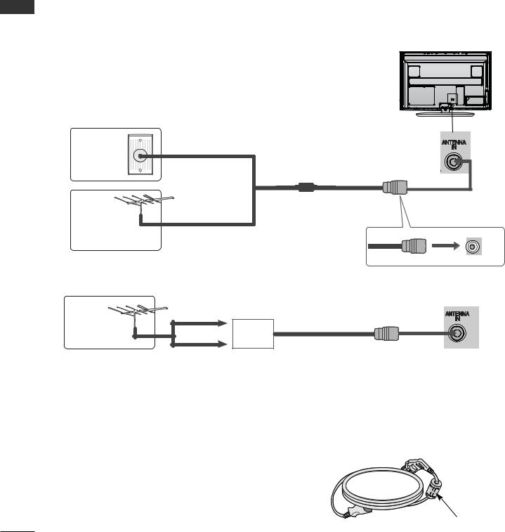
■ To prevent damage do not connect to the mains outlet until all connections are made between the devices.
ANTENNA CONNECTION
■For optimum picture quality, adjust antenna direction.
■An antenna cable and converter are not supplied.
Wall
Antenna
Socket
Outdoor
Antenna
(VHF, UHF)
Antenna
Multi-family Dwellings/Apartments (Connect to wall antenna socket)
RF Coaxial Wire (75 ohm)
Single-family Dwellings /Houses
(Connect to wall jack for outdoor antenna)
UHF
Signal
Amplifier
VHF
■In poor signal areas, to achieve better picture quality it may be necessary to install a signal amplifier to the antenna as shown above.
■If signal needs to be split for two TVs,use an antenna signal splitter for connection.
Use of ferrite core (This feature is not available for all models.)
Ferrite core can be used to reduce the electromagnetic wave when connecting the power cord. The closer the location of the ferrite core to the power plug, the better it is.
Install the power plug closely.
26
EXTERNAL EQUIPMENT SETUP
■To avoid damaging any equipment, never plug in any power cord until you have finished connecting all equipment.
■This section on EXTERNAL EQUIPMENT SETUP mainly uses diagrams for the Plasma TV models.
■Image shown may differ from your TV.
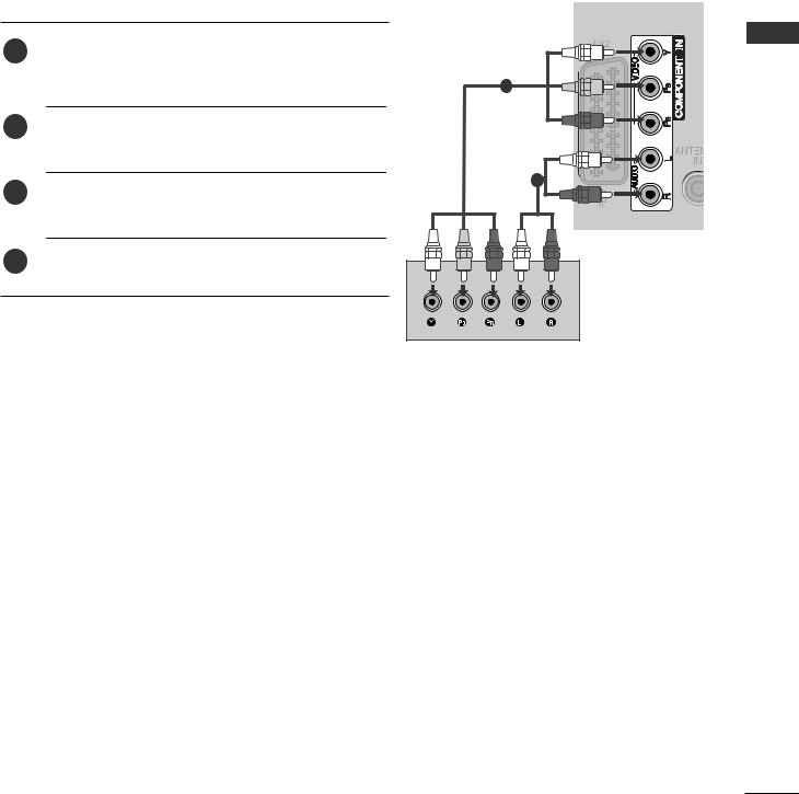
HD RECEIVER SETUP
■This TV can receive Digital RF/Cable signals without an external digital set-top box. However, if you do receive Digital signals from a digital set-top box or other digital external device, refer to the diagram as shown below.
Connecting with a Component cable |
|
|
1 |
Connect the video outputs (Y, PB, PR) of the digital set |
|
top box to the COMPONENT IN VIDEO jacks on the |
|
|
|
|
|
|
TV. |
1 |
2 |
Connect the audio output of the digital set-top box to |
|
|
the COMPONENT IN AUDIO jacks on the TV. |
|
3 |
Turn on the digital set-top box. |
2 |
|
||
|
(Refer to the owner’s manual for the digital set-top box.) |
|
4 |
Select Component |
input source using the INPUT |
|
|
button on the remote control.
Signal |
Component |
HDMI |
|
|
|
|
|
|
|
|
|
480i/576i |
O |
X |
|
480p/576p |
O |
O |
|
720p/1080i |
O |
O |
|
1080p |
O |
O |
|
(50/60Hz only) |
(24Hz/30Hz/50Hz/60Hz) |
||
|
|||
|
|
|
SETUP EQUIPMENT EXTERNAL
27
EXTERNAL EQUIPMENT SETUP
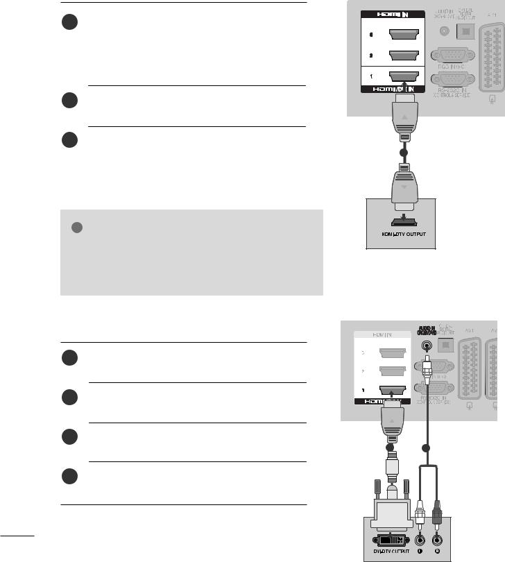
Connecting a set-top box with an HDMI cable
|
|
1 |
Connect the digital set-top box to HDMI/DVI IN 1, HDMI IN |
|||
|
|
2(Except for 19/22LH20**), HDMI IN 3 (Except for |
|
|||
|
|
|
|
|||
|
|
|
19/22LU40**, 19/22LU50**, |
|
|
|
|
|
|
19/22/26/32/37/42LH20**, 32/37/42LF25**) or HDMI |
|||
EXTERNAL |
|
IN 4 (Only 32/37/42/47LH49**, 32/37/42/47LH50**, |
|
|||
|
(Refer to the owner’s manual for the digital set-top box.) |
|||||
|
|
|
32/37/42/47LH70**, 50/60PS70**, 50/60PS80**) jack on the TV. |
|||
EQUIPMENT |
2 |
Turn on the digital set-top box. |
|
|
||
3 |
Select HDMI1, HDMI2(Except for |
19/22LH20**), |
||||
|
|
|||||
|
|
HDMI3 (Except for 19/22LU40**, |
19/22LU50**, |
|||
|
|
|
||||
|
|
|
19/22/26/32/37/42LH20**, 32/37/42LF25**) |
or |
||
|
|
|
HDMI4(Only 32/37/42/47LH49**, 32/37/42/47LH50**, |
|||
SETUP |
|
32/37/42/47LH70**, 50/60PS70**, 50/60PS80**) |
input |
|||
|
source using the INPUT button on the remote control. |
|||||
|
|
|
||||
|
|
|
|
|
|
|
|
|
! |
NOTE |
|
|
|
G Check that your HDMI cable is version 1.3 or higher.
If the HDMI cables don’t support HDMI version 1.3, flickering or no screen display can result. Please use the latest cables that support at least HDMI version 1.3.
Connecting with an HDMI to DVI cable
1Connect the digital set-top box to HDMI/DVI IN 1 jack on the TV.
2Connect the audio output of the digital set-top box to the AUDIO IN (RGB/DVI) jack on the TV.
3Turn on the digital set-top box. (Refer to the owner’s manual for the digital set-top box.)
4Select HDMI1 input source using the INPUT button on the remote control.
1
1 |
2 |
28
 Loading...