


KitchenAid K45SS, KSM75, KSM90, KSM103, KSM110 User Manual
...SERVICE MANUAL for
KITCHENAID
STAND MIXER
Models K45SS |
KSM75 |
KSM90 |
KSM103 |
KSM110 |
KSM150 |
KSM151 |
K5SS |
KSM5 |
KSM50P |
KSMC50 |
KPM5 |
KPM50 |
KP50P |
Printed in U.S.A. |
September, 2005 |
LIT4177310-C |

KITCHENAID
Stand Mixer Service Manual Lit4177310-C 2005 KITCHENAID
Safety Guidelines
This Service Manual is written for the Professional Service Technician who has familiarity with the KitchenAid Stand Mixer. The following Safety Guidelines should be adhered to when servicing this product.
SERVICE ENVIRONMENT
•The workplace will be dry and sanitary at all times and all units should be inspected for cleanliness before any work is started.
•Visually inspect the unit requiring service in a well luminated area.
•A mild, non-abrasive dishwashing soap solution and clean towel can be used to wash any unit requiring attention.
•The hands of the service technician should be clean at all times during service procedure.
ELECTRICAL CONSIDERATIONS
•The workplace for the stand mixer will have properly grounded AC outlets that adhere to all Local Electrical Codes that are applicable at the time of repair.
•The Stand Mixer Power Cord should always be inspected first before testing the mixer operation. Do NOT run the mixer if the Power Cord is damaged -- replace it.
•All disassembly and assembly procedures discussed in this manual should be conducted with the unit disconnected from the AC mains.
•Do NOT leave the unit unattended while running the mixer for speed range and bowl clearance checks. Always unplug the unit immediately after concluding these tests.
Technician
•The Service Technician should wear Protective Eyewear at all times when conducting a repair on the Stand Mixer.
•Loose fitting sweaters, shirts sleeves or bracelets should NOT be worn while servicing the Stand Mixer.
SAFETY

KITCHENAID
Stand Mixer Service Manual Lit4177310-C 2005 KITCHENAID
INDEX: Stand Mixer Repair Manual
K45SS KSM75 KSM90 KSM103 KSM110 KSM150 KSM151
K5SS KSM5 KSM50P KSMC50 KPM5 KPM50 KP50P
SECTION |
SUBJECT |
PAGE |
- |
General Information |
1 |
1 |
Disassembly of Gearcase and Planetary |
2 |
2 |
Disassembly of Motor and Control Unit |
6 |
3 |
Repairs to Motor and Control Unit |
11 |
4 |
Repairs to Gearcase and Planetary |
16 |
5 |
Repairs to Pedestal |
21 |
6 |
Adjustment to Control Unit |
22 |
7 |
Repairs to Bowl Lift Assembly |
26 |
8 |
Troubleshooting the Bowl Lift Assembly |
30 |
APPENDIX |
SUBJECT |
|
A |
Tools Required for Stand Mixer Service |
|
B |
Problem Solving Quick Reference Guide |
|
C |
Domestic Model Wiring Diagram |
|
D |
International Model Wiring Diagram - RF Filter |
|
E |
International Model Wiring Diagram - Bowl Interlock RF Filter |
|
F |
Stand Mixer Serial Number Codes |
|
Introduction
All KitchenAid Stand Mixers are well designed and carefully built. Normally they will give continual use year after year without service attention.
Careful records have been maintained over a period of years to determine and correct, through improved design, any troubles that might possibly develop.
An effort has been made in preparation of this manual to cover them all.
INDEX

KITCHENAID
Stand Mixer Service Manual LIT4177310-C 2005 KitchenAid
Heating
GENERAL INFORMATION Normal Performance
The KitchenAid Stand Mixer is powered with a universal motor which will operate on 50 or 60 hertz, alternating current only.
The Voltage of the power supply should be within 10 volts either way of the voltage stamped on the mixer trimband and nameplate.
A mixer in good running condition will start turning slowly when the switch lever is moved from the “OFF” position to the “STIR” position.
As the switch lever is moved to successively higher positions, the speed of the beater increases until the #10 speed is reached.
At stir position, the planetary should turn at approximately 60 RPM; at the #10 position all models turn at approximately 255 RPM, with the exception of K45SS models built before May 6th, 2002 (WM19), which turn at approximately 280 RPM.
KITCHENAID STAND MIXER RPM
SPEED |
*K45SS |
OTHER MODELS |
STIR |
60 RPM |
60 RPM |
#10 |
255 RPM |
255 RPM |
Prior to May 6th, 2002, |
|
|
#10 |
280 RPM |
|
*Note: All models have similar RPM, except K45SS units built before May 6th, 2002, which run at 280 RPM in the #10 position.
The mixer will run quietly in the lower speed range; however, some noise can be expected on the higher speed settings due to hum of gears and the motor.
When the mixer is first turned to the stir position, there may be a slight clattering, irregular noise. This noise will disappear as the lubrication in the gearcase warms up.
The switch lever should move freely with the “feel” of definite positions for speed numbers stir, 2, 4, 6, 8 and 10. Speed numbers 3, 5, 7 and 9 do not have definite notches.
Power
A mixer will have full power on all speed settings. To check for full power, carefully hold the planetary with one hand and move the switch lever on and off with the other hand.
At the stir position, it should not be possible to stall the planetary except by a very great effort; nor should the planetary slow down noticeably when the retarding pressure is applied.
Under normal conditions, the mixer will not show any tendency to heat because of the built-in ventilating system in the motor.
Under heavy loads with extended mixing time periods, the head may heat up to the point of being uncomfortable to touch.
Speed Control
The speed control of the mixer is attained through the use of a governor assembly mounted at the rear of the control plate assembly.
The electrical circuit is made and broken by the action of the fly ball governor revolving against the control plate.
When the switch lever is moved to an ON position, the position of the control plate with respect to the governor is changed by the action of the switch lever. Thus, when the control plate is set close to the governor, a relatively low speed of the motor causes the governor to make or break the mixer’s electrical circuit through the control plate.
When the control plate is set farther away, a greater motor speed is required before the governor starts breaking the circuit.
The action of the governor is such that the speed of the motor will remain constant for a given setting of the control plate within certain loads.
After certain loads have been exceeded, the speed of the motor will drop to meet the torque requirements of the given load.
Speed is controlled by the governor and the control plate in conjunction with the phase control.
TRIAC RMS VOLTAGE
BOTH CONTACTS OPEN - 40 VOLTS ONE CONTACT OPEN - 80 VOLTS
BOTH CONTACTS CLOSED - FULL VOLTAGE NOTE: The triac regulates the power the motor sees
depending on control board contacts.
A device called a triac is a part of the phase control circuit.
This device determines the amount of power the motor sees dependent upon the condition of the control board contacts.
If both contacts are open, about 40 volts RMS is applied to the motor and about 80 volts is applied when either contact is closed and the other is open.
PAGE 1
KITCHENAID
Stand Mixer Service Manual LIT4177310-C 2005 KitchenAid
When both contacts are closed, the triac is full on; consequently, full power is applied to the motor. In this way, the speed is controlled.
If the mixer motor begins to run too fast for a particular speed setting, one or both contacts open, which cuts back on the voltage the motor sees, thus slowing it up.
If the motor operation becomes too slow, one or both contacts will close, applying the needed voltage to the motor to sufficiently increase motor speed.
This is always accomplished through the triac. The control plate contacts control the triac, and in turn, controls the amount of power supplied to the motor.
BEATER
The beater should fit freely on the beater shaft located in the planetary.
Power is transmitted from the motor to the center-bevel gear assembly by means of the worm gear.
The center-bevel gear assembly engages the beater pinion, located in the planetary, to turn the beater shaft.
The attachment hub bevel gear also meshes with the center-bevel gear assembly to transmit power when various attachments are being used.
LUBRICATION
SECTION 1
DISASSEMBLY OF THE GEARCASE AND
PLANETARY
A.All solid state KitchenAid mixers have the same motor and control parts and the gears in the gearcase are alike, with one exception: “K45SS units built prior to May 6th, 2002.”
Planetary parts are all the same, except that some early production K5SS had a lead weight. Gearing and motor instructions are for both tilt head and bowl lift machines and any differences will be pointed out.
BOWL LIFT - Models K5SS,KSM5,KSM50, KSMC50,KPM5, KPM50, KP50. The bowl is raised and lowered into position.
TILT HEAD - Models K45SS, KSM45, KSM75, KSM90, KSM103, KSM110, KSM150, KSM151, KSM152. The mixer head is tilted up and down into position.
Bowl, column, base and bowl lift details are covered separately in section 7.
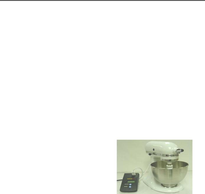
B.Before repairs are attempted on any KitchenAid mixer, a wattmeter test should be made. To make the test, set the wattmeter to the proper voltage. Next, plug the cord from the mixer into the wattmeter. Turn on the current and run the mixer.
Under normal service conditions, the mixer will not require lubrication for many years.
The gear case is lubricated with an ample supply of Benalene 930-2 grease (6 fluid ounces), which lubricates all the gears and shafts.
GEARCASE LUBRICATION |
|
|
All KitchenAid Stand Mixer Gearcases are |
|
|
lubricated with 6 Fluid Ounces of: |
|
KitchenAid stand mixer shown with a digital wattmeter |
BENALENE 930-2 GREASE (OR EQUIVALENT) |
|
|
|
If the wattmeter shows up to 135 watts, going from |
|
NOTE: Gearcases lubricated with this grease |
|
|
|
stir to #10 speed, the mixer is in good condition. |
|
will not require lubrication for years. |
|
|
|
If the wattmeter reading is 175 to 400 watts, there |
|
|
|
|
The motor bearing and the beater shaft bearing |
|
is a problem. |
|
High wattage mixer readings indicate either |
|
are oil impregnated. |
|
|
|
electrical or mechanical problems. |
|
The rear motor bearing has a felt washer which |
|
|
|
Check first for bearing/gear drag, then for |
|
has been presoaked in oil. |
|
|
|
motor/brush problems. |
|
The front motor bearing in the mixer housing is |
|
|
|
CAUTION: Always remove power cord from |
|
a ball bearing. |
|
|
|
electrical outlet before servicing any part of the |
|
|
|
|
|
|
mixer. |
|
PAGE 2 |
|
KITCHENAID
Stand Mixer Service Manual LIT4177310-C 2005 KitchenAid
C. Note: remove the bowl and any attachments before disassembly of unit.
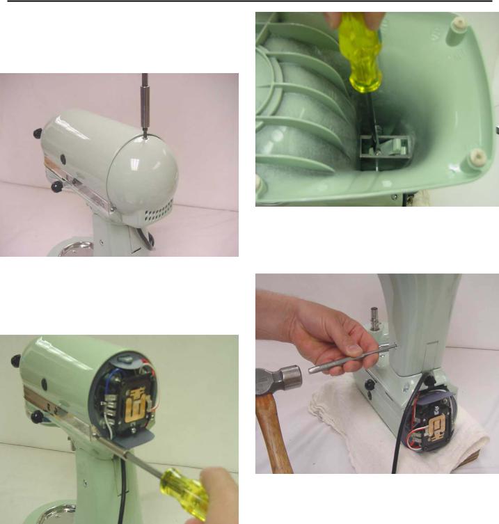
Remove the #6-32x3/8” (tapered head) screw from the end cover (Fig. 1).
Fig. 1 The end cover is removed by removing the tapered head endcover screw.
Remove the two #6-32x3/16” screws that hold the trimband to the gearcase-motor housing (Fig. 2). With the screws removed, take the trimband off and set aside.
Fig. 2 The trimband can be removed after removing the trimband screws.
D. To save the paint, lay the unit in a padded cradle or on a cloth pad.
To remove the pedestal from the gearcase-bottom cover, turn the unit upside down in a padded cradle. Loosen the set screw with a screwdriver (Fig. 3)
Fig. 3 Loosen the hinge pin setscrew to remove the pedestal from the bottomcover.
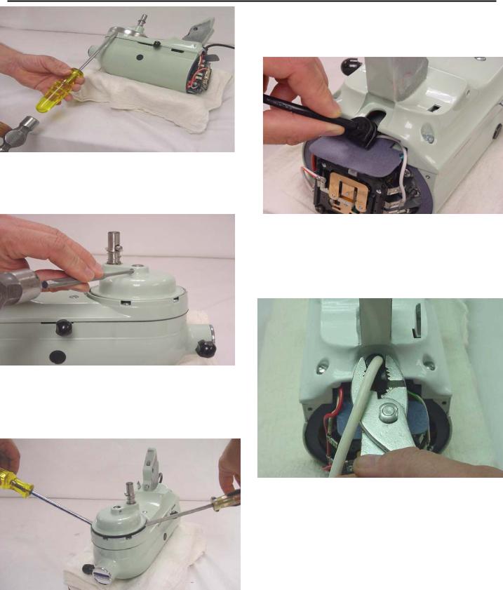
Using a drift punch and hammer, drive out the hinge pin (Fig. 4) and lift the pedestal off the gearcase-bottom cover.
Fig. 4 A drift punch and hammer is used to drive out the hinge pin.
E. To remove the planetary, first remove the drip ring . Use a screwdriver on the upper edge of the drip ring and gently tap the screwdriver to remove the drip ring (Fig. 5).
PAGE 3
KITCHENAID
Stand Mixer Service Manual LIT4177310-C 2005 KitchenAid
F. Remove the power cord from the bottom cover by sliding the molded strain relief out of the slot in the bottom cover (Fig. 8).
Fig. 5 The Drip Cup fits tightly and must be started off by tapping it.
With a 5/32” drift punch, remove the groove pin that holds the planetary to the vertical center shaft (Fig. 6).
Fig. 6 Removal of the groove pin that holds the planetary to the vertical center shaft
With the pin out, the planetary can be removed from the center shaft. Using two (2) screwdrivers, pry the planetary up and off the shaft (Fig. 7).
Fig. 8 Pull back on the molded strain relief to remove the power cord from the slot in the bottom cover.
To remove the power cord with the Heyco strain relief used on older models, use a pair of pliers to squeeze the strain relief while pulling up (Fig. 9). Reverse this procedure to reinstall it.
Fig. 9 Removal of Heyco strain relief using pliers.
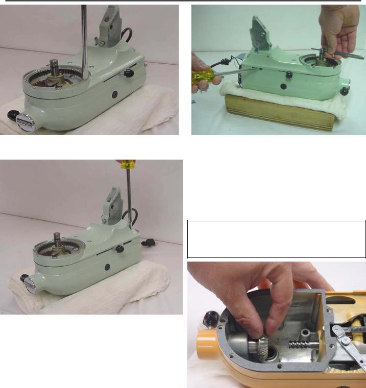
G. To remove the bottom cover from the gearcasemotor housing, unscrew the five (5) #10-24 special screws (Fig. 10). These screws hold the internal gear into the bottom cover.
Next remove the four (4) filister head screws from the bottom cover (Fig. 11).
Fig. 7 Use two screwdrivers to pry the planetary off the
shaft.
Page 4
KITCHENAID
Stand Mixer Service Manual LIT4177310-C 2005 KitchenAid
Fig. 10 Removal of the 5 special screws holding the internal gear in the bottom cover.
Fig. 12 While lifting up on the center shaft, use a screw driver to gently pry the bottom cover from the housing.
H. Remove the attachment hub bevel gear from the gearcase-motor housing.
This gear is removed by simply pulling it out of the attachment hub (Fig. 13). The gear will clear the worm of the motor’s armature shaft and should be easy to remove.
Note: For clarity, the pictures in this manual have
no grease shown in the gearcase. Normally the gearcase has 6 oz. of grease surrounding the gears.
Fig. 11 The bottom cover is removed after removing the four #10-24 filister head screws.
To remove the bottom cover from the gearcasemotor housing, insert a drift punch through the hole in the center shaft and lift, while using a screwdriver to break the bottom cover loose.
Use the slots in the side of the gearcase to do this (Fig. 12).
Do NOT pry in the area of the transmission gasket, as this may prevent the gasket from sealing properly upon reassembly.
The transmission gears will come out with the bottom cover. Be careful not to allow any grease to fall into the motor area of the housing.
Fig. 13 The attachment hub bevel gear being removed from the mixer attachment hub bearing.
I. Clean out the gearcase and remove as much of the grease as possible.
The gearcase may be thoroughly cleaned when the motor has been removed.
Page 5
KITCHENAID
Stand Mixer Service Manual LIT4177310-C |
2005 KitchenAid |
||||
|
|
SECTION 2 |
Remove the end seal and disconnect the phase |
||
|
DISASSEMBLY OF STAND MIXER MOTOR |
control flag terminals from the control board |
|||
|
|
AND CONTROL UNIT |
(Fig. 16). |
|
|
|
|
Note: All service operations discussed |
|
|
|
|
|
here should be performed with the mixer |
|
|
|
|
|
disconnected from the A. C. mains. |
|
|
|
A. Start the disassembly of the control unit by |
|
|
|||
removing the cord flag terminals from the control |
|
|
|||
board and the ground wire from the bearing bracket |
|
|
|||
(Fig. 14). |
|
|
|||
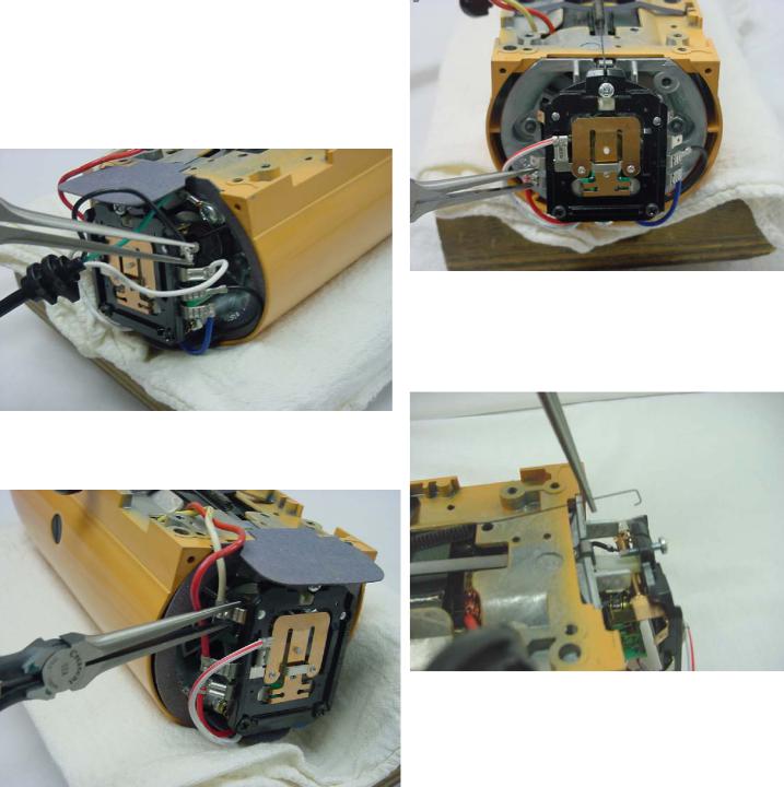
Fig. 14 Removal of the cord flag terminals and cord ground wire.
Remove the motor stator flag terminals from the control board ( Fig. 15).
Fig. 15 The removal of the motor stator flag terminals from the control board.
Fig. 16 After removing the end seal, remove the phase control flag terminals.
Unhook the control board spring at the bottom of the control board (Fig. 17).
Fig. 17 Unhook the control board spring.
Unlock the two lock nuts on the control board and unscrew the two adjusting screws.
The mixer control board can now be removed and set aside for later evaluation (Fig. 18 ).
Page 6

KITCHENAID
Stand Mixer Service Manual LIT4177310-C 2005 KitchenAid
Fig. 18 Mixer housing with end seal and control board removed.
B. The phase control can now be disassembled from the bearing bracket, if necessary, by unscrewing the #4-40 x 1/4” pan head screw (Figs. 19 & 20).
Fig. 19 Removal of the phase control (Triac) from the bearing bracket.
C. With a pair of needle nose pliers, carefully pry off the governor assembly. (Fig. 21) Do NOT bend.
Remove the governor drive pin and lay it aside so it will not be lost (Fig. 22).
Fig. 20 Phase control or (triac) shown removed in lower center.
Fig. 21 Needle nose plier used to pry governor off the motor shaft.
Fig. 22 Governor shown removed from the shaft of the motor.
Page 7
KITCHENAID
Stand Mixer Service Manual LIT4177310-C 2005 KitchenAid
D. To remove the speed control link and cam
assembly, take out the pivot screw and tension washer (Fig. 24).
Flat Spring
Fig. 25 Removing the speed control spring, flat spring and the speed control link assembly.
E. Unscrew and remove the two #10-24 nuts (Fig. 26).
Fig. 24 The pivot screw and tension washer are removed with a phillips screwdriver.
Before removing the speed control link and cam assembly, remove the control board spring from the link.
The flat spring is removed as you remove the speed control link assembly.
The speed control link and cam assembly can be removed by pulling it out of the gearcase-motor housing (Fig. 25).
Fig. 26 Two 10-24 nuts are removed from the bearing bracket.
Remove the bearing bracket (Fig. 27).
Now remove the motor stud sleeve from the stator stud (Fig. 28).
Page 8
KITCHENAID
Stand Mixer Service Manual LIT4177310-C 2005 KitchenAid
Fig. 27 Bearing bracket being removed after two #10-24 nuts have been removed.
Fig. 28 The motor stud sleeve is shown being removed after bearing bracket removal.
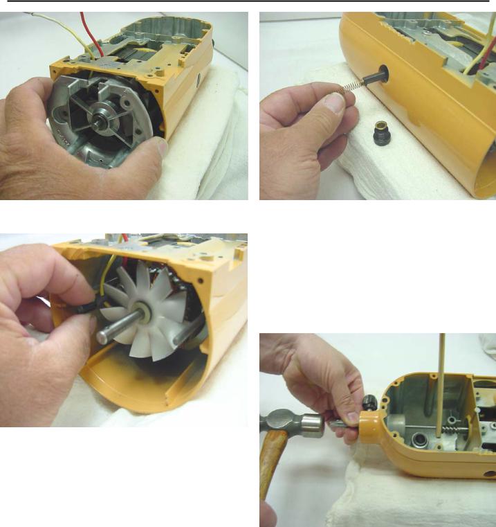
F. Unscrew the two brush holder screw caps and remove the brushes and springs (Fig. 29).
Viewing from the rear, mark the brushes right and left, and also the top of the brush, just as it was removed from the motor.
Fig. 29 the brush holder caps are loosened to access brushes for removal. Make sure to mark orientation.
G. The armature can now be removed.
With the attachment hub bevel gear removed, insert a drift punch through the attachment hub opening and gently tap the armature back through the stator using a block of wood to protect the shaft (Fig. 30).
Fig. 30 A block of wood is used to protect the motor shaft when removing the armature.
Remove the worm end bearing washer and the fan end spacer washer.
Page 9
KITCHENAID
Stand Mixer Service Manual LIT4177310-C 2005 KitchenAid
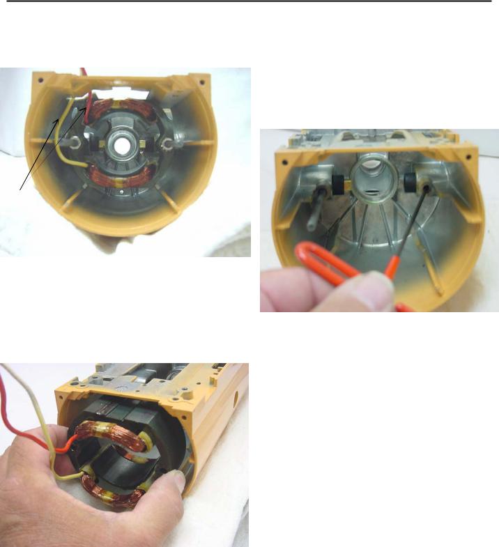
H. Pull the two wires from the rear of the stator through the slot in the gearcase-motor housing so they are inside the gearcase-motor housing and sticking out the back (Fig. 31).
I. To remove the brush holder , it will be necessary to remove the other stator stud. Under the stator studs are #10-24x1/4 cup point screws. To remove the set screws, use a 3/32” Allen wrench; older models may use a flat screwdriver (Fig. 33).
Stator Wires
Fig. 31 Wire orientation inside the gearcase-motor housing
Using long pliers, pull the brush slips from the stator out of the brush holders. Note orientation of stator clip in brush holder.
Remove the two #10-24 nuts from the stator studs and carefully set aside for use during reassembly. Unscrew one stator stud and pull out the stator (Fig. 32).
Fig. 33 Removing the brush holder set screws with a allen wrench.
Unscrew the set screws a few turns and (from inside the housing) push the brush holder out by hand. Note the orientation of the brush insert inside the brush holder.
Fig. 32 The stator is shown being removed from the motor housing.
To pull the stator out, reach into the motor housing
and grasp the stator |
and pull it out. Caution: Do |
not nick or damage the copper coil wires on |
|
the motor. |
Page 10 |
 Loading...