


PERFORMANCE
AV1
DIGITAL SURROUND PROCESSOR/CONTROLLER
USER GUIDE

IMPORTANT SAFETY INSTRUCTIONS
1.Read these instructions.
2.Keep these instructions.
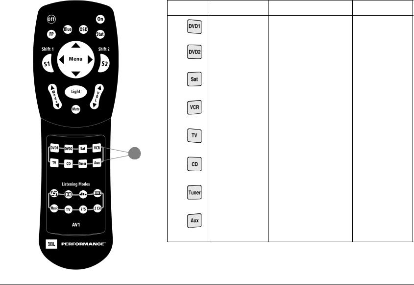
3.Heed all warnings.
4.Follow all instructions.
5.Do not use this apparatus near water.
6.Clean only with a dry cloth.
7.Do not block any ventilation openings. Install in accordance with the manufacturer’s instructions.
8.Do not install near any heat sources such as radiators, heat registers, stoves, or another apparatus (including amplifiers) that produces heat.
9.Do not defeat the safety purpose of the polarized or grounding-type plug. A polarized plug has two blades with one wider than the other. A grounding-type plug has two blades and a third grounding prong. The wide blade or the third prong are provided for your safety. If the provided plug does not fit into your outlet, consult an electrician for replacement of the obsolete outlet.
10.Protect the power cord from being walked on or pinched particularly at plugs, convenience receptacles, and the point where they exit from the apparatus.
11.Only use attachments/accessories specified by the manufacturer.
12.Use only with the cart, stand, tripod, bracket, or table specified by the manufacturer, or sold with the apparatus. When a cart is used, use caution when mov-
ing the cart/appartus combination to avoid injury from tip-over.
13.Unplug this apparatus during lightning storms or when unused for long periods of time.
14.Refer all servicing to qualified service personnel. Servicing is required when the apparatus has been damaged in any way, such as when a power-supply cord or plug is damaged, liquid has been spilled or objects have fallen into the apparatus, the apparatus has been exposed to rain or moisture, does not operate normally, or has been dropped.
•Refer to the manufacturer’s operating instructions for power requirements. Be advised that different operating voltagesmayrequiretheuseofdifferentlinecordand/or attachment plug.
•Do not install the unit in an unventilated rack, or directly above heat-producing equipment such as power amplifiers. Observe the maximum ambient operating temperature listed in the product specification.
•Never attach audio power amplifier outputs directly to any of the unit’s connectors.
This equipment has been tested and found to comply with the limits for a Class B digital device, pursuant to Part 15
 To reduce the risk of fire or electric shock, WARNING do not expose this apparatus to rain or
moisture. Do not place objects containing liquid, such as vases, on this apparatus.
of FCC Rules. These limits are designed to provide reasonable protection against harmful interference in a residential installation. This equipment generates, uses, and radiates radio frequency energy and, if not installed and used in accordance with the instructions, may cause harmful interference to radio or television reception, which can be determined by turning the equipment off and on. The user is encouraged to try to correct the interference by one or more of the following measures:
•Re-orient or relocate the receiving antenna.
•Increase the separation between the equipment and the receiver.
•Connect the equipment into an outlet on a circuit different from that to which the receiver is connected.
•Consult the dealer or an experienced radio/television technician for help.

JBL Performance
8500 Balboa Boulevard Northridge, CA 91329 250 Crossways Park Drive Woodbury, NY 11797 USA 800-336-4JBL
Part No. 070-16959 Rev 0 12/04
Manufactured under license from Dolby Laboratories. “Dolby,” “Pro Logic’” and the double-D symbol are trademarks of Dolby Laboratories. “Surround EX” is a jointly developed technology of THX and Dolby, Laboratories, Inc., and is a registered trademark of Dolby. Used under authorization.
THX, Ultra and Ultra2 are trademarks of THX Ltd., which may be registered in some jurisdictions. All rights reserved.
Manufactured under license from Lucasfilm Ltd. U.S. Patent Nos. 5,043,970; 5,189,703; and/or 5,222,056. European Patent No. 0323830. Other U.S. and foreign patents pending. Lucasfilm is a trademark of Lucasfilm Ltd. Surround EX is a trademark of Dolby Laboratories. Used under authorization.
“DTS,” “DTS-ES,” “Neo:6,” and”DTS 96/24” are trademarks of Digital Theater Systems, Inc.
SACD is a trademark of Sony Electronics, Inc.
SHARC is a Trademark of ANALOG DEVICES, INC.
“Lexicon,” “LOGIC7,” and the L7 logo are registered trademarks of Harman International Industries, Inc. U.S. Patent Nos. D454,553; D454,860; 5,796,844; 5,870,480 and other worldwide patents issued and pending.
© 2004 JBL Performance. All rights reserved.
This document should not be construed as a commitment on the part of JBL Performance. The information it contains is subject to change without notice. JBL Performance assumes no responsibility for errors that may appear within this document.

Introduction |
JBL Performance |
DOCUMENTATION CONVENTIONS
This document contains general safety, installation and operation instructions for the AV1 Digital Controller. It is important to read this user guide before attempting to use the product. Pay particular attention to safety instructions.
The following symbols are used in the document:
Appears on the component to indicate the presence of uninsulated, dangerous voltage inside the enclosureævoltage that may be sufficient to constitute a risk of shock.
Appears on the component to indicate important operating and maintenance instructions in the accompanying literature.
WARNING
Calls attention to a procedure, practice, condition or the like that, if not correctly performed or adhered to, could result in injury or death.
CAUTION! Calls attention to a procedure, practice, condition or the like that, if not correctly performed
or adhered to, could result in damage or destruction to part or all of the product.
SETUP 

 INPUTS

 DVD1
DVD1 

 NAME
NAME 

 EDIT INPUT NAME
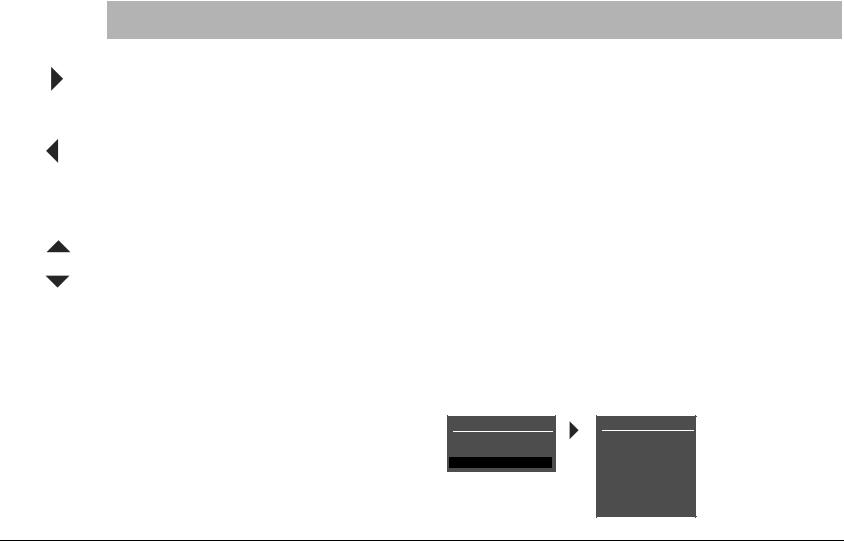
Represents a menu path. The menu items in gray boxes must be selected with the remote control Menu arrow to access the menu or menu item in the black box. For instance, the SETUP, INPUTS, and DVD1 menu items must be selected to open the DVD1 INPUT SETUP menu.
The DVD1 INPUT SETUP menu is used here as an example and will continue to be used as an example throughout this document. Whenever it appears, any other INPUT SETUP menu may be substituted. Likewise, whenever the DVD1 input appears as a step in a menu path, any other input may be substituted.
Note: Calls attention to information that is essential to highlight.
This document uses the term DTS(-ES) to indicate that DTS-ES encoding may or may not be present in the input source.
ii

AV1 |
Introduction |
ENGLISH
IMPORTANT SAFETY INSTRUCTIONS
1Save these instructions for later use.
2 Follow all instructions and warnings marked on the unit.
3Follow all instructions and warnings marked on the unit.
4Always use with the correct line voltage. Refer to the manufacturer’s operating instructions for power requirements. Be advised that different operating voltages may require the use of a different line cord and/or attachment plug.
5Do not install the unit in an unventilated rack, or directly above heat producing equipment such as power amplifiers. Observe the maximum ambient operating temperature listed in the product specification.
6Slots and openings on the case are provided for ventilation; to ensure reliable operation and prevent it from overheating, these openings must not be blocked or covered. Never push objects of any kind through any of the ventilation slots. Never spill liquid of any kind on the unit.
7Never attach audio power amplifier outputs directly to any of the unit’s connectors.
8To prevent shock or fire hazard, do not expose the unit to rain or moisture, or operate it where it will be exposed to water.
9Do not attempt to operate the unit if it has been dropped, damaged, exposed to liquids, or if it exhibits a distinct change in performance indicating the need for service.
10This unit should only be opened by qualified service personnel. Removing covers will expose you to hazardous voltages.
This triangle, which appears on your component, alerts you to the presence of uninsulated, dangerous voltage inside the enclosure…voltage that may be sufficient to constitute a risk of shock.
This triangle, which appears on your component, alerts you to important operating and maintenance instructions in this accompanying literature.
DEUTSCH
WICHTIGE SICHERHEITSHINWEISE
1Bewahren Sie diese Anleitungen zur späteren Benutzung auf.
2Befolgen Sie alle Anleitungen und alle Warnhinweise auf dem Gerät
3Betreiben Sie das Gerät immer mit der korrekten Netzspannung. Angaben über den Strombedarf entnehmen Sie bitte den Betriebsanweisungen des Herstellers. Bei unterschiedlichen Betriebsspannungen kann die Verwendung anderer Netzkabel und/oder Anschlußstecker erforderlich werden.
4Bauen Sie das Gerät nie in ein unbelüftetes Rack oder direkt über Wärme erzeugenden Geräten wie Verstärkern ein. Beachten Sie die in der Produktspezifikation aufgeführte maximale Umgebungstemperatur für den Betrieb.
5Schlitze und Öffnungen in der Box dienen der Belüftung, damit das Gerät zuverlässig läuft und sich nicht überhitzt. Diese Öffnungen dürfen nicht abgedeckt oder blockiert werden. Auch dürfen keine Gegenstände in sie hineingesteckt werden. Verschütten Sie niemals Flüssigkeiten, gleich welcher Art, auf das Gerät.
6Schließen Sie niemals Stromausgänge des Audioverstärkers direkt an das Gerät an.
7Zur Vermeidung von elektrischen Schlägen oder Brandgefahr darf das Gerät weder Regen noch Feuchtigkeit ausgesetzt oder an Orten betrieben werden, wo es mit Wasser in Berührung kommen kann.
8Versuchen Sie nie, das Gerät zu betreiben, wenn es fallen gelassen, beschädigt oder Flüssigkeiten ausgesetzt wurde oder wenn ein deutlicher Leistungsunterschied zu verzeichnen ist, der darauf hinweist, dass es gewartet werden muss.
9Dieser Apparat sollte nur von qualifizierten Fachleuten geöffnet werden. Das Abnehmen von Abdeckungen setzt Sie gefährlichen Spannungen aus.
Dieses Dreieck, welches auf Ihrem Bauteil angebracht ist, warnt Sie vor dem Vorhandensein nicht isolierter gef hrlicher Spannung im Gerät. Diese Spannung kann so hoch sein, dass das Risiko eines Stromschlags besteht.
Dieses Dreieck, welches auf Ihrem Bauteil angebracht ist, macht Sie auf wichtige Betriebsund Wartungshinweise in diesen Hinweisen aufmerksam.
v
Introduction |
JBL Performance |
ESPAÑOL
INSTRUCCIONES DE SEGURIDAD IMPORTANTES
1Guarde estas instrucciones para futuras referencias.
2Siga todas las instrucciones y tenga en cuenta las advertencias que aparecen en la unidad y en las instrucciones de funcionamiento.
3Utilice siempre la tensión de línea correcta. Consulte las instrucciones del fabricante, donde se especifican los requisitos de alimentación. Tenga en cuenta que unas tensiones operativas diferentes pueden precisar de la utilización de diferentes cables de alimentación y/o enchufes.
4No instale la unidad en un rack sin ventilación, o directamente sobre equipos que generen calor, como amplificadores de potencia. Tenga en cuenta la temperatura operativa ambiental máxima que se detalla en las especificaciones del producto.
5Las ranuras y aberturas del equipo son para su ventilación - para garantizar un funcionamiento fiable y evitar que la unidad se sobrecaliente, no bloquee, cubra o inserte objetos en las aberturas. No derrame nunca líquidos de ningún tipo sobre la unidad.
6Nunca conecte directamente salidas de amplificadores de potencia de audio a ninguno de los conectores de la unidad.
7Para evitar descargas eléctricas o incendios, no exponga la unidad a la humedad o la lluvia, ni la utilice donde pueda estar expuesta al agua.
8No intente utilizar la unidad si ésta ha caído, se ha dañado, ha estado expuesta a líquidos, o si muestra un cambio importante en sus prestaciones, lo cual indicaría la necesidad de una reparación.
9Das Esta unidad deberá ser abierta únicamente por personal calificado. Si usted quita las coberturas se expondrá a voltajes peligrosos.
Este tri ngulo, que aparece en su componente, alerta de la presencia de una tensi n peligrosa no aislada en el interior del equipo - una tensi n que puede ser suficiente como para constituir un riesgo de descarga el ctrica.
Este tri ngjlo, que aparece en su equipo, le alerta de instrucciones operativas y de mantenimiento importantes en los documentos que acompa an el producto.
FRANÇAIS
INSTRUCTIONS IMPORTANTES RELATIVES À LA
SÉCURITÉ
1Conservez ces instructions pour pouvoir vous y référer ultérieurement.
2Suivez toutes ces instructions et tenez compte de tous les avertissements indiqués sur l’appareil et dans la documentation fournie avec l’appareil.
3Utilisez toujours la tension secteur correcte. Consultez les instructions du fabricant précisant les caractéristiques d’alimentation à respecter. Attention, le type de cordon secteur et/ou de prise secteur peut varier selon des tensions en vigueur dans l’installation.
4N’installez pas l’appareil dans un Rack mal ventilé ou directement audessus d’un appareil dégageant de la chaleur comme un amplificateur de puissance. Respectez la température maximale de fonctionnement précisée dans les caractéristiques techniques.
5Les ouvertures dans le boîtier assurent la bonne ventilation de l’appareil, évitent toute surchauffe et assurent le bon fonctionnement du système. Veillez à ne pas obstruer, couvrir ou insérer d’objets dans ces ouvertures. Veillez à ne pas renverser de liquide sur l’appareil.
6Ne reliez jamais directement les sorties audio des amplificateurs de puissance aux connecteurs de l’appareil.
7Afin d’éviter tout risque d’électrocution ou d’incendie, n’exposez pas l’appareil à la pluie ou à l’humidité ; ne l’utilisez pas dans des endroits exposés aux projections de liquides.
8N’essayez pas d’utiliser l’appareil si celui-ci est tombé, a été endommagé, exposé à des projections de liquides ou si vous constatez des dysfonctionnements nécessitant l’intervention d’un technicien spécialisé.
9Cet appareil ne doit être ouvert que par un personnel de service qualifié. En enlevant les couvercles vous vous exposez à des tensions électriques dangereuses.
Le symbole de l’ clair fl ch dans un triangle quilat ral sert alerter l’utilisateur sur la pr sence l’int rieur de l’appareil de tensions non isol es susceptibles de constituer un risque d’ lectrocution.
Le point d’exclamation dans un triangle quilat ral sert alerter l’utilisateur sur la pr sence de nombreuses instructions de maintenance dans le manuel fourni avec l’appareil.
vi
AV1 |
Introduction |
ITALIANO
IMPORTANTI NORME DI SICUREZZA
1Conservare le presenti norme per l’utilizzo futuro.
2Seguire sempre tutte le istruzioni e gli avvertimenti segnati sull’unità e nelle istruzioni operative.
3Utilizzare sempre la corretta tensione di alimentazione. Fare riferimento al manuale del costruttore per le caratteristiche di alimentazione. Tensioni di rete diverse necessitano anche di un diverso cavo con spine differenti.
4Non installare l’unità in un rack poco ventilato, o direttamente sopra apparecchiature che producono calore, come amplificatori di potenza. Controllare la massima temperatura ambientale di esercizio sulle specifiche tecniche del prodotto.
5Fori ed aperture nei pannelli sono necessari per garantire un corretta ventilazione e prevenire surriscaldamenti. Queste aperture non devono essere coperte o ostruite. Non inserire oggetti di alcun tipo nei fori di ventilazione. Evitare il contatto con liquidi di qualsiasi genere.
6Evitare di collegare le uscite di un amplificatore di potenza direttamente a qualsiasi connettore dell’unità.
7Per evitare il rischio di scosse elettriche non esporre il prodotto a pioggia o umidità. Evitare l’uso dove possa essere esposto all’acqua.
8Non tentare di utilizzare il prodotto se è caduto, se è stato a contatto con liquidi, o mostra chiari segni di danneggiamento o cambio di prestazioni che indicano la necessità di assistenza tecnica.
9Ogni intervento sull’unità va eseguito esclusivamente da personale qualificato. La rimozione della copertura comporta l’esposizione al pericolo di folgorazione.
Il presente triangolo impresso sul componente avverte la presenza di tensioni pericolose non isolate all interno della copertura – tali tensioni rappresentano un pericolo di folgorazione.
Il presente triangolo impresso sul componente avverte l utente della presenza nella documentazione allegata di importanti istruzioni relative al funzionamento ed alla manutenzione.
PORTUGUESE
INSTRUÇÕES IMPORTANTES DE SEGURANÇA
1Guarde essas instruções para uso posterior.
2Siga todas as instruções e fique atento aos avisos marcados na unidade e nas instruções de operação.
3Sempre use com a voltagem correta. Veja no manual de instruções do fabricante qual a alimentação necessária. Lembre-se que voltagens de operação diferentes podem precisar de um cabo ou plug diferentes.
4Não instale a unidade em um suporte sem ventilação ou diretamente acima de equipamentos que produzam calor, como transformadores. Observe a temperatura ambiente máxima de operação indicada na especificação do produto.
5O revestimento da unidade é provido de fendas e aberturas para ventilação – para assegurar uma operação confiável e evitar que a unidade se superaqueça. Não bloqueie, cubra ou insira objetos nas aberturas. Nunca derrube líquido de qualquer espécie na unidade.
6Nunca ligue saídas de amplificadores de áudio diretamente a qualquer dos conectores da unidade.
7Para evitar danos de choque ou fogo, não exponha a unidade à chuva ou umidade, ou opere-a onde haja exposição à água.
8Não tente operar a unidade se ela for derrubada, danificada, exposta à líquidos ou apresente uma mudança de performance notável, indicando a necessidade de manutenção.
9Esta unidade só deveria ser aberta através de pessoal de serviço qualificado. Removendo coberturas o exporão a voltagens perigosas.
Esse triângulo que aparece no seu console, alerta para a presença de voltagem perigosa e não isolada no recinto – voltagem que pode ser suficiente para constituir um risco de choque.
Esse triângulo ques aparece no seu console alerta para instruções importantes de operação e manutenção neste manual.
vii

Introduction |
JBL Performance |
DANSK
VIGTIG INFORMATION OM SIKKERHED
1Gem denne vejledning til senere brug.
2Følg alle anvisninger og advarsler på apparatet.
3Apparatet skal altid tilsluttes den korrekte spænding. Der henvises til brugsanvisningen, der indeholder specifikationer for strømforsyning. Der gøres opmærksom på, at ved varierende driftsspændinger kan det blive nødvendigt at bruge andre ledningsog/eller stiktyper.
4Apparatet må ikke monteres i et kabinet uden ventilation eller lige over andet udstyr, der udvikler varme, f.eks. forstærkere. Den maksimale omgivelsestemperatur ved drift, der står opført i specifikationerne, skal overholdes.
5Der er ventilationsåbninger i kabinettet. For at sikre apparatets drift og hindre over phedning må disse åbninger ikke blokeres eller tildækkes. Stik aldrig noget ind igennem ventilationsåbningerne, og pas på aldrig at spilde nogen form for væske på apparatet.
6Udgangsstik fra audioforstærkere må aldrig sættes direkte i apparatet.
7Apparatet må ikke udsættes for regn eller fugt og må ikke bruges i nærheden af vand for at undgå risiko for elektrisk stød og brand.
8Apparatet må aldrig bruges, hvis det er blevet stødt, beskadiget eller vådt, eller hvis ændringer i ydelsen tyder på, at det trænger til eftersyn.
9Dette apparat må kun åbnes af fagfolk. Hvis dækslet tages af, udsættes man for livsfarlig højspænding.
Denne mærkat på komponenten advarer om uisoleret, farlig spænding i apparatet - høj nok til at give elektrisk stød.
Denne mærkat på komponenten advarer om vigtig driftsog vedligeholdsinformation i den tilhørende litteratur.
SUOMI
TÄRKEITÄ TURVALLISUUSOHJEITA
1Säilytä nämä ohjeet tulevaa käyttöä varten.
2Seuraa kaikkia yksikköön merkittyjä ohjeita ja varoituksia.
3Käytä aina oikeaa verkkojännitettä. Tehovaatimukset selviävät valmistajan käyttöohjeista. Huomaa, että eri käyttöjännitteet saattavat vaatia toisenlaisen verkkojohdon ja/tai-pistokkeen käytön.
4Älä asenna yksikköä telineeseen jossa ei ole tuuletusta, tai välittömästi lämpöä tuotavien laitteiden, esim. tehovahvistimien, yläpuolelle.Ympäristön lämpötila käytössä ei saa ylittää tuotespesifikaation maksimilämpötilaa.
5Kotelo on varustettu tuuletusreiillä ja -aukoilla. Luotettavan toiminnan varmistamiseksi ja ylilämpenemisen välttämiseksi näitä aukkoja ei saa sulkea tai peittää. Mitään esineitä ei saa työntää tuuletusaukkoihin.
Mitään nesteitä ei saa kaataa yksikköön.
6Älä kytke audiotehovahvistimen lähtöjä suoraan mihinkään yksikön liittimeen.
7Sähköiskun ja palovaaran välttämiseksi yksikkö ei saa olla sateessa tai kosteassa, eikä sitä saa käyttää märässä ympäristössä.
8Älä käytä yksikköä jos se on pudonnut, vaurioitunut, kostunut, tai jos sen suorituskyky on huomattavasti muuttunut, mikä vaatii huoltoa.
9Yksikön saa avata vain laitteeseen perehtynyt huoltohenkilö. Kansien poisto altistaa sinut vaarallisille jännitteille.
Tämä kolmio, joka esiintyy komponentissasi, varoittaa sinua eristämättömän vaarallisen jännitteen esiintymisestä yksikön sisällä. Tämä jännite saattaa olla riittävän korkea aiheuttamaan sähköiskuvaaran.
Tämä kolmio, joka esiintyy komponentissasi, kertoo sinulle, että tässä tuotedokumentoinnissa esiintyy tärkeitä käyttöja ylläpitoohjeita.
viii
AV1 |
Introduction |
NORSK
VIKTIG INFORMASJON OM SIKKERHET
1Ta vare på denne veiledningen for senere bruk.
2Følg alle anvisningene og advarslene som er angitt på apparatet.
3Apparatet skal alltid anvendes med korrekt spenning. Produktbeskrivelsen inneholder spesifikasjoner for strømkrav. Vær oppmerksom på at det ved ulike driftsspenninger kan være nødvendig å bruke en annen ledningog/eller støpseltype.
4Apparatet skal ikke monteres i skap uten ventilasjon, eller direkte over varmeproduserende utstyr, som for eksempel kraftforsterkere. Den maksimale romtemperaturen som står oppgitt i produktbeskrivelsen, skal overholdes.
5Apparatet er utstyrt med ventilasjonsåpninger. For at apparatet skal være pålitelig i bruk\ og ikke veropphetes, må disse åpningene ikke blokkeres eller tildekkes. Stikk aldri noe inn i ventilasjonsåpningene, og pass på at det aldri søles noen form for væske på apparatet.
6Utgangsplugger fra audioforsterkere skal aldri koples direkte til apparatet.
7Unngå brannfare og elektrisk støt ved å sørge for at apparatet ikke utsettes for regn eller fuktighet og ikke anvendes i nærheten av vann.
8Apparatet skal ikke brukes hvis det har blitt utsatt for støt, er skadet eller blitt vått, eller hvis endringer i ytelsen tyder på at det trenger service.
9Dette apparatet skal kun åpnes av fagfolk. Hvis dekselet fjernes, utsettes man for livsfarlig høyspenning.
Komponenten er merket med denne trekanten, som er en advarsel om at det finnes uisolert, farlig spenning inne i kabinettet - høy nok til å utgjøre en fare for elektrisk støt.
Komponenten er merket med denne trekanten, som betyr at den tilhørende litteraturen inneholder viktige opplysninger om drift og ved.
SVENSKA
VIKTIGA SÄKERHETSFÖRESKRIFTER
1Spara dessa föreskrifter för framtida bruk.
2Följ alla anvisningar och varningar som anges på enheten.
3Använd alltid rätt nätspänning. Se tillverkarens bruksanvisningar för information om effektkrav. Märkväl, att andra matningsspänningar eventuellt kräver att en annan typs nätsladd och/eller kontakt används.
4Installera inte enheten i ett oventilerat stativ, eller direkt ovanför utrustningar som avger värme, t ex effektförstärkare. Se till att omgivningens temperatur vid drift inte överskrider det angivna värdet i produktspecifikationen.
5Behållaren är försedd med hål och öppningar för ventilering. För att garantera tillförlitlig funktion och förhindra överhettning får dessa öppningar inte blockeras eller täckas. Inga föremål får skuffas in genom ventilationshålen. Inga vätskor får spillas på enheten.
6Anslut aldrig audioeffektförstärkarutgångar direkt till någon av enhetens kontakter.
7För att undvika elstöt eller brandfara får enheten inte utsättas för regn eller fukt, eller användas på ställen där den blir våt.
8Använd inte enheten om den har fallit i golvet, skadats, blivit våt, eller om dess prestanda förändrats märkbart, vilket kräver service.
9Enheten får öppnas endast av behörig servicepersonal. Farliga spänningar blir tillgängliga när locken tas bort.
Denna triangel, som visas på din komponent, varnar dig om en oisolerad farlig spänning inne i enheten. Denna spänning är eventuellt så hög att fara för elstöt föreligger.
Denna triangel, som visas på din komponent, anger att viktiga bruksanvisningar och serviceanvisningar ingår i dokumentationen i fråga.
ix

Introduction |
JBL Performance |
Unpacking and Inspection
After unpacking the unit, save all packing materials in case the unit ever needs to be shipped. Thoroughly inspect the modules and packing materials for signs of damage. Report any damage to the carrier at once; report equipment malfunction to the dealer.
Auspacken und Überprüfung
Bewahren Sie nach dem Auspacken des Geräts das Verpackungsmaterial für den Fall auf, dass Sie das Gerät wieder versenden müssen. Überprüfen Sie die Module und die Verpackung sorgfältig auf Anzeichen von Beschädigung. Etwaige Schäden sind dem Transporteur unverzüglich anzuzeigen; Funktionsstörungen sind dem zuständigen Händler zu melden.
Desembalaje e Inspección
Después de desembalar la unidad, guarde todos los materiales de embalaje por si alguna vez transportar la unidad. Inspeccione con atención los módulos y los materiales de embalaje para comprobar que no muestren desperfectos. Informe inmediatamente de cualquier desperfecto al transportista; informe de cualquier problema de funcionamiento del equipo a su distribuidor.
 Contenu de L’emballage et Inspection
Après avoir ouvert l’emballage, conservez-le pour tout retour. Inspectez avec soin les modules et les matériaux d’emballage pour tout signe de dommage. Veuillez rapporter immédiatement les dommages auprès du transporteur. Les dysfonctionnements du matériel doivent être signalés à votre revendeur.
Disimballaggio ed Ispezione
Dopo aver disimballato l’unità, salvi tutto il materiale d’imballaggio, in caso Lei abbia bisogno di spedire l’unità. Ispezioni attentamente i moduli ed il materiale d’imballaggio per vedere se riportano segni di danno. Riporti subito ogni segno di danno al corriere; riferisca il malfunzionamento dell’attrezzatura al suo rivenditore.
Retirando a Embalagem e Inspecionando
Depois de desembalar a unidade, guarde a embalagem caso precise enviar a unidade para manutenção. Inspecione cuidadosamente o módulo e a embalagem procurando sinais de dano. Avise à loja qualquer tipo de dano ou mal funcionamento do equipamento.
x
AV1 |
Introduction |
Table of Contents
Documentation Conventions........................................................ |
ii |
Important Safety Instructions........................................................ |
v |
Wichtige Sicherheitshinweise........................................................ |
v |
Instrucciones De Seguridad Importantes....................................... |
vi |
Instructions Importantes Relatives À La Sécurité............................ |
vi |
Importanti Norme Di Sicurezza ................................................... |
vii |
Instruções Importantes De Segurança.......................................... |
vii |
Vigtig Information Om Sikkerhed ............................................... |
viii |
Tärkeitä Turvallisuusohjeita......................................................... |
viii |
Viktig Informasjon Om Sikkerhet .................................................. |
ix |
Viktiga Säkerhetsföreskrifter.......................................................... |
ix |
Unpacking and Inspection............................................................. |
x |
Auspacken und Überprüfung......................................................... |
x |
Desembalaje e Inspección ............................................................. |
x |
Contenu de L’emballage et Inspection .......................................... |
x |
Disimballaggio ed Ispezione .......................................................... |
x |
Retirando a Embalagem e Inspecionando ...................................... |
x |
Getting Started
About the AV1........................................................................... |
1-2 |
Highlights ............................................................................. |
1-3 |
Product Registration .................................................................. |
1-4 |
Installation Considerations......................................................... |
1-4 |
Remote Control Battery Installation ........................................... |
1-5 |
Basic Operation
Front-Panel Overview ................................................................ |
2-2 |
Rear-Panel Overview.................................................................. |
2-4 |
Remote Control Overview ......................................................... |
2-6 |
Operation Considerations ...................................................... |
2-6 |
Menu Navigation .................................................................. |
2-6 |
Main Menu ........................................................................... |
2-6 |
Menu Item Selection ............................................................. |
2-7 |
Command Bank Activation .................................................... |
2-9 |
Command Matrix ............................................................... |
2-10 |
Two-line Status ....................................................................... |
2-14 |
Status Menus .......................................................................... |
2-14 |
Status Menu Descriptions .................................................... |
2-15 |
Status Menu Parameter Descriptions ................................... |
2-18 |
Status Menu Level Meters ....................................................... |
2-20 |
Setup
Setup ........................................................................................ |
3-2 |
Input Setup ............................................................................... |
3-3 |
Changing Input Names (Name) ............................................ |
3-4 |
Assigning Audio & Video Input Connectors ........................... |
3-6 |
Selecting Preferred Listening Modes .................................... |
3-13 |
Configuring Advanced Settings ........................................... |
3-17 |
Speaker Setup ......................................................................... |
3-24 |
Custom Speaker Setups ....................................................... |
3-24 |
Thx Speaker Setups ............................................................. |
3-33 |
Measuring Speaker Distances .............................................. |
3-35 |
Calibrating Output Levels .................................................... |
3-37 |
Speaker Level Adjust ............................................................ |
3-40 |
Rear Panel Config.................................................................... |
3-43 |
Display Setup .......................................................................... |
3-45 |
On-screen Display Setup ..................................................... |
3-47 |
Front Panel Display Setup .................................................... |
3-50 |
Volume Control Setup............................................................. |
3-51 |
Trigger Setup .......................................................................... |
3-52 |
Lock Options........................................................................... |
3-54 |
Audio Controls
Audio Controls .......................................................................... |
4-2 |
iii

Introduction |
JBL Performance |
Mode Adjust |
|
Mode Adjust.............................................................................. |
5-2 |
Listening Mode Activation ......................................................... |
5-2 |
Preferred Listening Mode Selection |
|
Parameters ............................................................................ |
5-3 |
Mode And Buttons ....................................................... |
5-3 |
Mode Family Selection Buttons .............................................. |
5-3 |
Listening Mode Descriptions...................................................... |
5-4 |
Listening Mode Menu Option & Parameter Descriptions ......... |
5-29 |
Troubleshooting & Maintenance |
|
Troubleshooting ........................................................................ |
6-2 |
Routine Maintenance................................................................. |
6-3 |
Restoring Factory-default Settings.............................................. |
6-4 |
Appendix |
|
Specifications............................................................................. |
A-2 |
Declaration of Conformity ......................................................... |
A-4 |
Menu Tree................................................................................. |
A-5 |
Installation Worksheet ............................................................. |
A-14 |
iv

1
Getting Started
About the AV1............................................................................ |
1-2 |
Highlights . . . . . . . . . . . . . . . . . . . . . . . . . . . . . . . . . . . . . . . . . . . . . . . |
. 1-3 |
Product Registration ................................................................... |
1-4 |
Installation Considerations.......................................................... |
1-4 |
Remote Control Battery Installation ............................................ |
1-5 |

Getting Started |
JBL Performance |
ABOUT THE AV1
Thank you for purchasing the AV1 Digital Controller, an 8-channel audio and video control center. The AV1 includes eight configurable inputs, each of which can be assigned to its eight digital audio, eight analog audio, five composite video, five S-video or three component video input connectors. The analog connectors can be configured for up to two 5.1-channel sources.
Inside and out, the AV1 is designed for possible future developments. The rear panel houses two RS-232 connectors; one capable of performing configuration downloads and Flash memory software upgrades and the other capable of supporting future software developments.
More than just an audio and video control center, the AV1 offers the latest version of the critically acclaimed LOGIc7 decoding, which creates a 7.1-channel output signal from stereo, 5.1- and 6.1-channel sources. Unlike other decoders, LOGIC7 decoding is compatible with all input sources and requires no special encoding. Because the improvement it provides is clearly audible, LOGIC7 is widely regarded as the finest decoder available.
In addition to LOGIC7, the AV1 offers Dolby Digital Surround EX, Dolby Pro Logic™II, Dolby Pro Logic, DTS® 96/24, DTSNeo:6®, DTS-ES®, THX Ultra2™ and THX® Surround EX decoding. THX Ultra2 certification guarantees that the AV1 meets the highest THX specifications.
With four floating-point SHARC™ digital signal-processing (DSP) engines, the AV1 boasts enormous processing power. These powerful processors perform custom processing such as LOGIC7 decoding, bass enhancement, dialog enhancement, auto azimuth, 5- speaker enhancement, bass management, high-precision digital crossovers and audio controls. These features are available at sam-
ple rates up to 96kHz, with 24-bit resolution to retain top performance from all sources. In addition, a fifth DSP engine is dedicated to decoding multi-channel compressed audio sources.
The AV1 is one of the most advanced audio and video control centers available. High-precision 24-bit/96kHz A/D converters can be used to convert stereo analog audio input signals to digital signals, allowing the AV1 to provide the benefits of precise digital signal processing without sacrificing signal integrity. Alternatively, stereo analog signals can bypass A/D conversion and internal processing, following a pure signal path directly to the output connectors.
Digital audio input signals are processed through a two-stage phase lock loop for extremely low intrinsic jitter and high jitter rejection. Auto azimuth technology corrects timing and level imbalances in stereo sources, ensuring exceptionally accurate playback of surround-encoded sources.
1-2

AV1 |
Getting Started |
Complementing its audio performance, the AV1 features two broadcast-quality video switchers. A wide-bandwidth component video switcher accepts analog component or RGB video signals, while a composite and S-video switcher accepts high-quality NTSC, PAL or SECAM video signals. The component video switcher can pass high-definition TV (HDTV) signals, as well as standard-defini-
tion TV signals. Both switchers are designed to pass video signals without alteration or degradation.
Built to professional standards, the AV1 is designed to serve as the control center in any high-quality home theater. The most demanding enthusiast will be impressed with its unique combination of power, performance, flexibility and technological sophistication.
HIGHLIGHTS
•Eight channels
•Eight configurable inputs
•Four S/PDIF coaxial and four S/PDIF optical (Toslink) digital audio input connectors
•24-bit/192kHz D/A converters for all audio channels
•Two 5.1-channel analog audio input connectors
•Analog bypass option for stereo audio input connectors
•Auto switching between digital and analog audio input connectors
•Three component video input connectors with full HDTV compatibility
•Five S-video input connectors
•Five composite video input connectors
•Four 32-bit DSP engines
•Separate DSP engine for decoding compressed audio sources
•Broadcast-quality video switching
•LOGIC7 decoding
•Dolby Digital Surround EX, Dolby Pro Logic II, and Dolby Pro Logic decoding
•DTS 96/24, DTS-ES (discrete and matrix) and DTS Neo:6 decoding
•THX Ultra2 and THX Surround EX decoding
•THX Ultra2 certification
•Flash memory software upgrade capabilities
•RS-232 control
•Rear-panel IR input connector
•Two trigger outputs
•Optional 19-inch rack-mount kit
1-3

Getting Started |
JBL Performance |
PRODUCT REGISTRATION
Please register the AV1 Digital Controller within 15 days of purchase. Register online at www.JBL.com or complete and return the product registration card attached to the back cover of this user guide. Retain the sales receipt as proof of warranty coverage.
INSTALLATION CONSIDERATIONS
The AV1 requires special care during installation to ensure optimal performance. Pay particular attention to instructions below and to other precautions that appear throughout this user guide.
DO install the AV1 on a solid, flat, level surface such as a table or shelf. The AV1 can also be installed in a standard 19-inch equipment rack using an optional rack-mount kit available from an authorized JBL dealer.
DO select a dry, well-ventilated location out of direct sunlight.
DO NOT expose the AV1 to high temperatures, humidity, steam, smoke, dampness or excessive dust. Avoid installing the AV1 near radiators and other heat-producing appliances.
DO NOT install the AV1 near unshielded TV or FM antennas, cable TV decoders, or other RF-emitting devices that might cause interference.
DO NOT place the AV1 on a thick rug or carpet, or cover the AV1 with a cloth, as this might prevent proper cooling.
DO NOT place the AV1 on a windowsill or any location exposed to direct sunlight.
DO NOT obstruct the front-panel IR receiver window. The remote control must be in line of sight with the IR receiver for proper operation. See “Operation Considerations” on page 2-6 for more information.
DO NOT install the AV1 on a surface that is unstable or unable to support all four feet, unless it is installed in an equipment rack.
DO NOT stack the AV1 directly above heat-producing equipment such as a power amplifier.
CAUTION!
Before moving the AV1, power the unit off using the rearpanel power switch and unplug the power cord from the wall outlet.
1-4
AV1 |
Getting Started |
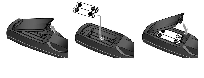
REMOTE CONTROL BATTERY INSTALLATION
The remote control requires two AA batteries. The batteries should be replaced as needed. Alkaline batteries, which last longer without leaking, are recommended. When battery power is low, the remote control enters a low-voltage condition, preventing it from operating the AV1. When this occurs, replace the batteries. Normal operation will resume when new batteries are installed.
To replace the remote control batteries:
1.Locate the battery compartment on the back of the remote control. Press the tab and lift the cover away from the remote control.
2.Remove old batteries (if applicable).
3.Observing the proper polarity, insert two AA batteries.
4.Align the cover over the battery compartment and gently press down until it snaps back into place.
5.Dispose of the old batteries (if applicable).
1-5

Getting Started |
JBL Performance |
1-6

2
Basic Operation
Front-Panel Overview ................................................................ |
2-2 |
Rear-Panel Overview .................................................................. |
2-4 |
Remote Control Overview ......................................................... |
2-6 |
Operation Considerations . . . . . . . . . . . . . . . . . . . . . . . . . . . . . . . . . . . . . 2-6
Menu Navigation . . . . . . . . . . . . . . . . . . . . . . . . . . . . . . . . . . . . . . . . . . . 2-6
Main Menu . . . . . . . . . . . . . . . . . . . . . . . . . . . . . . . . . . . . . . . . . . . . . . . 2-6
Menu Item Selection . . . . . . . . . . . . . . . . . . . . . . . . . . . . . . . . . . . . . . . . 2-7
Command Bank Activation . . . . . . . . . . . . . . . . . . . . . . . . . . . . . . . . . . . . 2-9
Command Matrix . . . . . . . . . . . . . . . . . . . . . . . . . . . . . . . . . . . . . . . . . 2-10
Two-line Status ........................................................................ |
2-14 |
Status Menus .......................................................................... |
2-14 |
Status Menu Descriptions . . . . . . . . . . . . . . . . . . . . . . . . . . . . . . . . . . . |
. 2-15 |
Status Menu Parameter Descriptions . . . . . . . . . . . . . . . . . . . . . . . . . . |
. 2-18 |
Status Menu Level Meters ........................................................ |
2-20 |
Basic Operation |
JBL Performance |
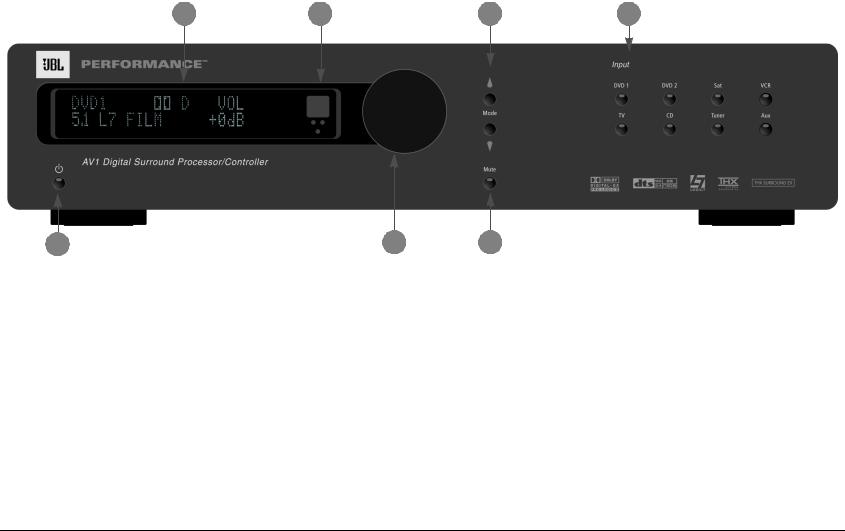
FRONT-PANEL OVERVIEW
The numbers in the front-panel illustration correspond with the numbered items below.
2 |
3 |
1 |
4 |
1 STANDBY BUTTON
Use the Standby button to activate or deactivate standby mode. The Standby button performs no function when the AV1 is powered off with the rear panel power switch.
When in standby mode, pressing the Standby button activates the AV1. When standby mode is deactivated, pressing the Standby button activates standby mode and deactivates the AV1. The red standby button LED lights indicating that standby mode is activated.
5 |
7 |
6
2 FRONT-PANEL DISPLAY
Use the Front-Panel display to view the current input, listening mode, input source and volume level. The 2 x 20 character display also functions as a display for messages and menus. See “Menu Navigation” on page 2-6 for more information.
2-2
AV1 |
Basic Operation |
3 IR RECEIVER
The IR Receiver receives infrared commands from the AV1 remote control. There are three associated LEDs.
•The amber LED blinks when a remote control command is received.
•The red LED lights when the A/D converters are overloading.
•The blue LED lights when the AV1 is powered on and activated
– even if the FRONT PANEL DISPLAY menu STATUS parameter is set to ALWAYS OFF.
Red LED |
|
|
|
Amber LED |
|
|
Blue LED 

4 VOLUME KNOB
Use the Volume knob to adjust volume level.
To adjust the volume level:
Rotate the volume knob clockwise to increase
VOLUME
or counterclockwise to decrease volume level 

 in 1dB increments. A horizontal bar graph
  indicating the current volume level is displayed in the on-screen and front-panel displays. The volume range is –80 to +6dB.
Note:
When AV1 output levels have been properly calibrated, the +0dB volume level setting corresponds to THX reference levels (75dB).
5 MODE & BUTTONS
Use the Mode buttons to scroll to the previous and next available listening mode. Scrolling occurs in the order shown in the MODE ADJUST menu. Press the Mode button to scroll upward through available listening modes. Press the Mode button to scroll downward through available listening modes. See “Listening Mode Activation” on page 5-2 for more information.
6 MUTE BUTTON
Use the Mute button to mute the AV1 volume or to restore the AV1 volume to its original level. Press the Mute button to lower the volume level; "MUTE ON" appears in the on-screen and front-panel displays. Press the Mute button again to restore the AV1 volume to its original level. See“Volume Control Setup” on page 3-51 for information about using the MUTE LEVEL parameter to set mute levels.
Mute may be activated automatically or manually. For example, the AV1 briefly activates mute when changing input sources or listening modes. The amber Mute button LED lights whenever mute is activated.
7 INPUT SELECTION BUTTONS
Select the AV1 input. The blue input selection button LEDs light whenever the corresponding input is selected.
2-3

Basic Operation |
JBL Performance |
REAR-PANEL OVERVIEW
The numbers in the rear-panel illustration correspond with the numbered items below.
8 |
3 |
6 |
7 |
1 |
|||
|
|
|
|
|
|
|
|
|
|
|
|
|
|
|
|
|
|
|
|
|
|
|
|
|
|
|
|
|
|
|
|
|
|
|
|
|
|
|
|
|
|
|
|
|
|
|
|
|
|
10 |
9 |
4 |
5 |
2 |
||||
|
|
|
||||||
1 POWER SWITCH |
|
|
|
|
3 DIGITAL AUDIO INPUT CONNECTORS (S/PDIF) |
|||
Use the Power switch to power the AV1 on or off. The I and O positions represent "on" and "off" status respectively. When the AV1 is powered on, the front-panel Standby button or remote control On button can be used to activate and deactivate standby mode. When the AV1 is powered off, standby mode is not available.
Provide digital audio input. Four S/PDIF coaxial and four S/PDIF optical (Toslink) input connectors are available. Connectors are compatible with PCM (44.1kHz, 48kHz, 88.2kHz and 96kHz), Dolby Digital and DTS(-ES) sources. Connectors are not compatible with MPEG (MP3) sources.
2 AC INPUT CONNECTOR
Provides power to the AV1 through the supplied power cord (3 wire, 10 amp, IEC 320).
Caution!
Never make or break connections to the AV1 unless all associated components are powered off.
2-4

AV1 |
Basic Operation |
4 ANALOG AUDIO INPUT CONNECTORS
Provide analog audio input. Eight stereo analog audio input connectors labeled 1 to 8 are available. Connectors labeled 3, 4, 5, 6, 7 and 8 can be configured as 5.1-channel connectors.
When a 5.1-channel analog audio source is present, input signals are sent to the audio output connectors as indicated in the table below.
Input Connector |
Output Connector |
|
|
(L) |
Front L |
|
|
(R) |
Front R |
|
|
(C) |
Center |
|
|
(SUB) |
Subwoofer |
|
|
(LS) |
Side L and Rear L |
|
|
(RS) |
Side R and Rear R |
5 AUDIO OUTPUT CONNECTORS
Provide analog audio output. Eight connectors, labeled Front L/R, Center, Subwoofer, Side L/R and Rear L/R are available.
6 VIDEO INPUT CONNECTORS
Provide video input. Five composite video connectors labeled Video 1 to 5, five S-video connectors labeled S-Video 1 to 5, and three component video connectors labeled 1 to 3 are available.
7 VIDEO OUTPUT CONNECTORS
Provide video output. One composite video connector, one S-video connector, and one component video connector are available.
Note:
•Composite video output connectors are available when a composite source is present.
•S-video output connectors are available when an S-video source is present.
•Component video output connectors are available when a component, composite or S-video source is present.
8 IR IN CONNECTOR
Accepts input of IR signals from infrared distribution equipment. One 3.5mm jack that accepts a stereo plug (Tip/Ring connection) or mono plug (Tip/Sleeve connection) is available.
9 RS-232 CONNECTORS
The RS-232 serial connector (1) is used to perform configuration downloads and flash memory software upgrades. The RS-232 connector (2) is capable of supporting future developments.
10 TRIGGER OUTPUT CONNECTORS
The AV1 is equipped with one 5-pin DIN connector, which provides three 12V DC outputs for controlling compatible components. The figure below shows how the connector is configured. The Power Trigger pin is not user programmable, Trigger (1) is user programmable, Trigger (2) is an inverted sense from Trigger (1) and is not independently programmable. The Power Trigger is “on” when the AV1 is not in Standby and is “off” when the AVI is in Standby or powered down. Trigger (1) is user configurable by remote control, Input Selection, or Mode Selection. See“Trigger Setup” on page 3-52 for more information.
Power Trigger |
|
Ground |
Trigger 1 |
|
Trigger 2 |
|
Ground |
|
|
|
2-5

Basic Operation |
JBL Performance |
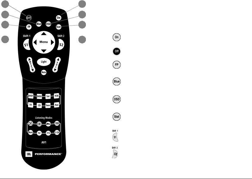
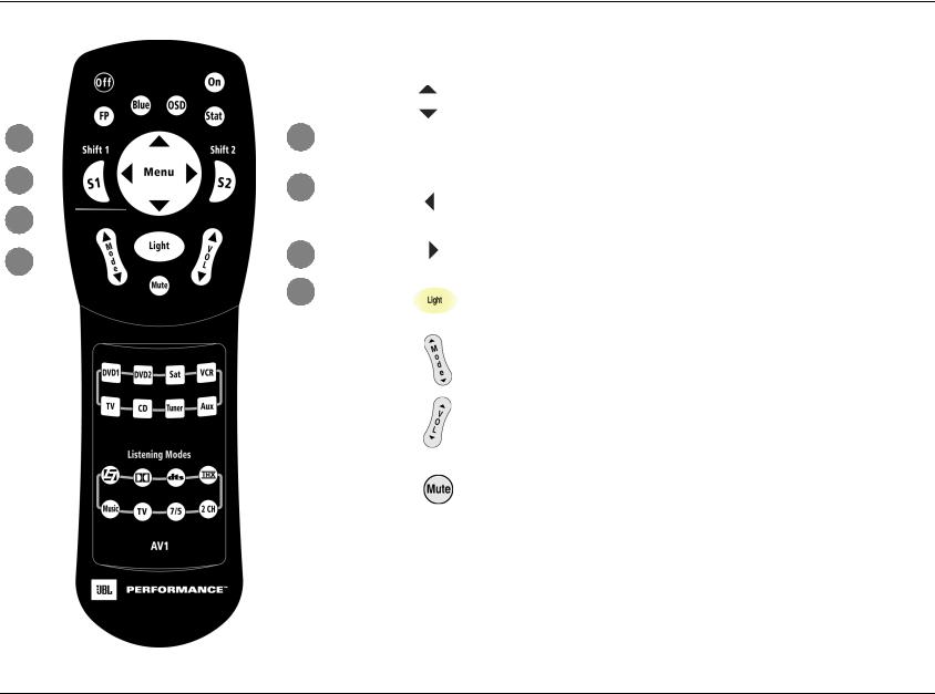
REMOTE CONTROL OVERVIEW
The AV1 remote control provides full operation of the AV1, including commands such as menu navigation that are not available from the front-panel. The command matrix that beginning on page 2-10 indicates the commands remote control buttons perform when each command bank is active. The numbered items in the matrix correspond with the remote control illustrations on pages 2-10 to 2-13.
OPERATION CONSIDERATIONS
The following factors can improve or impede remote control operation.
Note the following before operating the AV1 remote control:
•The remote control must be in line-of-sight with the frontpanel IR receiver. Eliminate obstructions between the remote control and the IR receiver. The remote control may become unreliable if strong sunlight or fluorescent light shines on the IR receiver.
•For optimal performance, position the remote control at a 30 degree angle no more than 17 feet (5m) from the AV1. Placing the AV1 inside a smoked glass cabinet will reduce the remote control range.
•Remote controllers for different components can interfere with one another. Avoid using remote controls for different components at the same time.
•Remote control batteries should be replaced as needed. See page 1-5 for battery installation instructions.
MENU NAVIGATION
Use the remote control Menu arrows to navigate the extensive menu structure shown in the Appendix (A-5 to A-13). The table on the previous page indicates the navigation functions remote control Menu arrows perform.
MAIN MENU
The MAIN MENU, shown to the right, represents the beginning of the menu structure. Use the MAIN MENU to open the three main
menu branches: MODE ADJUST, AUDIO CONTROLS, and SETUP. See Sections 3, 4,
and 5 for information about these menu branches.
2-6
AV1 |
Basic Operation |
MENU ITEM SELECTION
Use the remote control Menu arrows to select menu items.
Arrow |
Navigation Function(S) |
|
|
|
|||
|
|
|
|
|
|
||
|
|
|
• |
When a menu is open, press the Menu |
arrow to select the highlighted menu item. |
||
|
|
|
• When all menus are closed, press the Menu |
arrow to open the MAIN MENU. |
|||
|
|
|
|
|
|
||
|
|
|
• |
When a menu is open, press the Menu |
arrow to close the menu and, in most cases, open the previous menu. Subse- |
||
|
|
|
|
quent presses continue to close the current menu and open the previous menu until the MAIN MENU is closed. When |
|||
|
|
|
|
the MAIN MENU is closed, the menu structure is also closed. |
|
||
|
|
|
• |
When no menus are open, pressing the Menu |
arrow performs no function. |
||
|
|
|
• |
When a parameter drop-down menu (next page) is open, press the Menu |
arrow to select the current setting and |
||
|
|
|
|
close the drop-down menu. |
|
|
|
|
|
|
|
|
|
|
|
|
|
|
• When a menu is open, press the Menu |
and |
arrows to scroll upward ( |
) and downward ( ) through the complete |
|
|
|
|
|
list of menu items. The highlighted menu item appears on the front-panel display. All menu items appear in the on- |
|||
|
|
|
|
screen display. A scroll bar appears on the right side of the on-screen display when menu items exceed the on-screen |
|||
|
|
|
|
||||
|
|
|
|
display top and bottom margins. The cursor automatically wraps to the next menu item when the first or last menu item |
|||
|
|
|
|
is passed. |
|
|
|
|
|
|
|
|
|
|
|
|
|
|
|
|
|
|
|
To select a menu item on the open menu:
1. Press the remote control and arrows to highlight the desired menu item.
2.When the desired menu item is highlighted, press the arrow to select the highlighted item. If an option is selected, another menu opens. If a parameter is selected, a parameter drop-down menu opens.
MENU OPTIONS
Selecting a menu option opens another menu within the menu structure. For example, selecting the MAIN MENU SETUP option opens the SETUP menu.
MAIN MENU
MODE ADJUST AUDIO CONTROLS
SETUP
SETUP
INPUTS SPEAKERS
REAR PANEL CONFIG DISPLAYS
VOLUME CONTROLS TRIGGER
LOCK OPTIONS
2-7

Basic Operation |
JBL Performance |
MENU PARAMETERS
Selecting a menu parameter opens a drop-down menu or horizontal bar graph that is used to select the desired setting.
PARAMETER DROP-DOWN MENUS
Selecting some menu parameters opens a drop-down menu that contains a list of available parameter settings. For example, selecting the DISPLAY SETUP menu CUSTOM NAME parameter opens the drop-down menu shown below, which is used to select the ON or OFF setting.
DISPLAY SETUP |
|
|
O N |
ON-SCREEN DISPLAY |
|
|
OFF |
|
|
|
|
FRONT PANEL DISPLAY |
|||
A/V SYNC DELAY |
OFF |
||
CUSTOM NAME |
OFF |
|
|
EDIT CUSTOM NAME
To select the desired setting on a parameter drop-down menu:
1. When the drop-down menu opens, press the remote control and arrows to scroll upward and downward through the complete list of available settings. The current setting appears beneath the parameter name on the on-screen and front-panel displays.
2.When the desired setting appears beneath the parameter name, press the arrow to select the setting and close the drop-down menu.
HORIZONTAL BAR GRAPHS
Selecting some menu parameters opens a horizontal bar graph. The bar graph indicates the position the current parameter setting falls within the entire parameter range. The setting appears to the right of the parameter name in the on-screen and front-panel displays.
For example, selecting the DISPLAY SETUP menu A/V SYNC DELAY parameter opens the horizontal bar graph shown below, which is used to adjust the amount of audio delay.
DISPLAY SETUP
ON-SCREEN DISPLAY FRONT PANEL DISPLAY
A/V SYNC DELAY |
OFF |
CUSTOM NAME |
OFF |
EDIT CUSTOM NAME
OFF, 1 to 60ms
To adjust a parameter setting with a horizontal bar graph:
1. When the horizontal bar graph appears, press the remote control and arrows to increase or decrease the setting in designated increments. The setting appears to the right of the parameter name in the on-screen and frontpanel displays.
2.When the desired adjustments have been made, press the arrow to select the setting and close the horizontal bar graph.
2-8

AV1 |
Basic Operation |
COMMAND BANK ACTIVATION
The remote control buttons perform different commands depending on which command bank is activated. The remote control contains three command banks:
•default
•S1 (Shift 1)
•S2 (Shift 2)
The default command bank remains activated unless the Shift 1 or Shift 2 command bank is activated.
The Shift 1 and Shift 2 buttons themselves do not send commands to the AV1. When pressed and held, these buttons activate the associated command bank. For instance, pressing the remote control L7 button selects the Logic 7 listening mode. Pressing and holding the Shift 1 button while pressing the L7 button selects the Panorama listening mode. Pressing and holding the Shift 2 button while pressing the L7 button selects the PARTY listening mode.
The default command bank does not need to be activated; it remains activated unless the Shift 1 or Shift 2 command bank is activated.
•Pressing and holding the remote control S1 button activates the Shift 1 command bank.
•Pressing and holding the remote control S2 button activates the Shift 2 command bank.
•The S1 and S2 buttons themselves do not send commands to the AV1. When pressed and held, these buttons activate the associated command bank.
To activate the Shift 1 or Shift 2 command bank:
1.Press and hold the remote control S1 button or S2 button to activate one of the command banks.
2.While holding the selected button, press the desired remote control button to send the associated command to the AV1.
3.Release the S1 or S2 button to deactivate the associated command bank.
The ON-SCREEN DISPLAY menu REMOTE STATE parameter controls the remote control command bank indicator. When the REMOTE STATE parameter is set to ON, a command bank indicator appears in the top-right corner of the on-screen display indicating the last command bank used. When the REMOTE STATE parameter is set to OFF, no command bank indicator appears on the on-screen display.
•A "1" appears when a command from the Shift 1 command bank was received last.
•A "2" appears when a command from the Shift 2 command bank was received last.
•No letter appears when a command from the default command bank was received last.
2-9
Basic Operation |
JBL Performance |
2 |
|
|
1 |
|
4 |
|
|
5 |
|
3 |
|
|
6 |
|
7 |
|
|
|
8 |
|
|
|||
COMMAND MATRIX
The command matrix describes the commands remote control buttons perform when each command bank is active.
Button |
Main Zone |
Shift 1 |
Shift 2 |
|
|
|
|
|
|
1 |
Deactivates standby mode and |
Reserved for possible |
Reserved for possible |
|
activates the AV1. |
future expansion. |
future expansion. |
||
|
||||
|
|
|
|
|
2 |
Activates standby mode and |
Reserved for possible |
Reserved for possible |
|
deactivates the AV1. |
future expansion. |
future expansion. |
||
|
||||
|
|
|
|
|
3 |
Toggles the FRONT PANEL |
Centers the AUDIO CON- |
Reserved for possible |
|
DISPLAY menu STATUS param- |
TROLS menu BALANCE |
future expansion. |
||
|
||||
|
eter between ALWAYS OFF and |
and FADER parameters. |
|
|
|
its current setting. |
|
|
|
|
|
|
|
|
4 |
Toggles the ON-SCREEN DIS- |
Deactivates the trigger out- |
Sets the AUDIO CON- |
|
PLAY menu BACKGROUND |
put connector (1) when |
TROLS menu BASS, |
||
|
||||
|
parameter between ON and |
the connector is config- |
TREBLE, and TILT EQ |
|
|
OFF. |
ured for remote operation. |
parameters to +0.0dB. |
|
|
|
|
|
|
5 |
Toggles the ON-SCREEN DIS- |
Activates the trigger output |
Reserved for possible |
|
PLAY menu STATUS parameter |
connector labeled 1 when |
future expansion. |
||
|
||||
|
between ALWAYS OFF and its |
the connector configured |
|
|
|
current setting. |
for remote operation. |
|
|
|
|
|
|
|
6 |
Displays the two-line status for |
Toggles between opening |
Reserved for possible |
|
2 seconds. |
and closing the STATUS |
future expansion. |
||
|
||||
|
|
menu for the current input |
|
|
|
|
source. |
|
|
|
|
|
|
|
7 |
Activates an additional bank of commands that control the AV1. See “Command Bank |
|||
Activation” on page 3-9 for more information. |
|
|||
|
|
|||
|
|
|||
8 |
Activates an additional bank of commands that control the AV1. See “Command Bank |
|||
Activation” on page 3-9 for more information. |
|
|||
|
|
|||
|
|
|
|
|
2-10
AV1
9
10
12
13
|
|
|
|
|
|
|
|
|
|
|
|
|
|
|
|
|
|
|
|
|
|
|
|
Basic Operation |
|
|
|
|
|
|
|
|
|
|
|
|
|
|
|
|
|
|
|
|
|
|
|
||
|
|
|
|
|
|
|
|
|
|
|
|
|
|
|
|
Button |
Main Zone |
Shift 1 |
|
Shift 2 |
||||
|
|
|
|
|
|
|
|
|
|
|
|
|
|
|
|
|
|
|
|
|
|
|
|
|
|
|
|
|
|
|
|
|
|
|
|
|
|
|
|
|
9 |
|
|
Scroll upward ( ) and |
Adjust the AUDIO |
|
Increase ( ) and decrease |
||
|
|
|
|
|
|
|
|
|
|
|
|
|
|
|
|
|
|
CONTROLS menu FADER |
||||||
|
|
|
|
|
|
|
|
|
|
|
|
|
|
|
|
|
|
|
downward ( |
) through |
( ) the output level of the |
|||
|
|
|
|
|
|
|
|
|
|
|
|
|
|
|
|
|
|
|
parameter forward ( |
) and |
||||
|
|
|
|
|
|
|
|
|
|
|
|
|
|
|
|
|
|
|
menu items. |
|
audio output connector |
|||
|
|
|
|
|
|
|
|
|
|
|
|
|
|
|
|
|
|
|
|
|||||
|
|
|
|
|
|
|
|
|
|
|
|
|
|
|
11 |
|
|
|
|
|
backward ( |
). |
|
labeled Subwoofer as applied |
|
|
|
|
|
|
|
|
|
|
|
|
|
|
|
|
|
|
|
|
|
|
|
|
to the activated listening |
|
|
|
|
|
|
|
|
|
|
|
|
|
|
|
|
|
|
|
|
|
|
|
|
mode. |
|
|
|
|
|
|
|
|
|
|
|
9 |
|
|
|
|
|
|
|
|
|
||||
|
|
|
|
|
|
|
|
|
|
|
10 |
|
|
Closes the current menu. |
Adjusts the AUDIO CON- |
Reserved for possible future |
||||||||
|
|
|
|
|
|
|
|
|
|
|
|
|
|
|
|
|
|
|||||||
|
|
|
|
|
|
|
|
|
|
|
|
|
|
|
|
|
|
|
||||||
|
|
|
|
|
|
|
|
|
|
|
|
|
|
|
|
|
|
|
|
|
TROLS menu BALANCE |
expansion. |
||
|
|
|
|
|
|
|
|
|
|
|
|
|
|
|
|
|
|
|
|
|
||||
|
|
|
|
|
|
|
|
|
|
|
|
|
|
|
|
|
|
|
|
|
parameter left. |
|
|
|
|
|
|
|
|
|
|
|
|
|
|
|
|
|
|
|
|
|
|
|
|
|
|
||
|
|
|
|
|
|
|
|
|
|
|
|
|
|
|
|
|
|
|
|
|
|
|
|
|
|
|
|
|
|
|
|
|
|
|
|
|
|
14 |
11 |
|
|
Opens the menu structure |
Adjusts the AUDIO CON- |
Reserved for possible future |
|||||
|
|
|
|
|
|
|
|
|
|
|
|
|
|
|
|
and selects the highlighted |
TROLS menu BALANCE |
expansion. |
||||||
|
|
|
|
|
|
|
|
|
|
|
|
|
|
|
||||||||||
|
|
|
|
|
|
|
|
|
15 |
|
|
|
menu item. |
|
parameter right. |
|
|
|||||||
|
|
|
|
|
|
|
|
|
|
|
|
|
|
|
|
|
|
|||||||
|
|
|
|
|
|
|
|
|
12 |
|
|
Activates the remote control backlight, making remote control buttons more visible in |
||||||||||||
|
|
|
|
|
|
|
|
|
|
|
|
|
|
|
|
|
|
|
||||||
|
|
|
|
|
|
|
|
|
|
|
|
|
|
|
|
|
|
|
the dark. |
|
|
|
|
|
|
|
|
|
|
|
|
|
|
|
|
|
|
|
|
|
|
|
|
|
|
|
|
||
|
|
|
|
|
|
|
|
|
|
|
|
|
|
|
|
13 |
|
|
Scroll to the previous ( ) |
Sets the volume level to -15 |
Reserved for possible future |
|||
|
|
|
|
|
|
|
|
|
|
|
|
|
|
|
|
|
|
dB ( ) or -30 dB ( |
). |
expansion. |
||||
|
|
|
|
|
|
|
|
|
|
|
|
|
|
|
|
|
|
|
and the next ( |
) available |
||||
|
|
|
|
|
|
|
|
|
|
|
|
|
|
|
|
|
|
|
listening mode. |
|
|
|
|
|
|
|
|
|
|
|
|
|
|
|
|
|
|
|
|
|
|
|
|
|
|
|
|
|
|
|
|
|
|
|
|
|
|
|
|
|
|
|
|
|
|
14 |
|
|
Increases ( ) and |
Increases ( |
) and |
|
Reserved for possible future |
|
|
|
|
|
|
|
|
|
|
|
|
|
|
|
|
|
|
|
|
expansion. |
|||||
|
|
|
|
|
|
|
|
|
|
|
|
|
|
|
|
|
|
|
decreases ( |
) the volume |
decreases ( |
) the volume |
||
|
|
|
|
|
|
|
|
|
|
|
|
|
|
|
|
|
|
|
|
|||||
|
|
|
|
|
|
|
|
|
|
|
|
|
|
|
|
|
|
|
level in 1 dB increments. |
level in 3 dB increments. |
|
|||
|
|
|
|
|
|
|
|
|
|
|
|
|
|
|
|
|
|
|
|
|
|
|
|
|
|
|
|
|
|
|
|
|
|
|
|
|
|
|
|
|
15 |
|
|
Toggles between lowering |
Toggles between fully mut- |
Reserved for possible future |
|||
|
|
|
|
|
|
|
|
|
|
|
|
|
|
|
|
|
|
|
||||||
|
|
|
|
|
|
|
|
|
|
|
|
|
|
|
|
|
|
|
the volume level and restor- |
ing volume level and restor- |
expansion. |
|||
|
|
|
|
|
|
|
|
|
|
|
|
|
|
|
|
|
|
|
ing the volume to its |
ing the volume to its original |
|
|||
|
|
|
|
|
|
|
|
|
|
|
|
|
|
|
|
|
|
|
original level. |
|
level. |
|
|
|
|
|
|
|
|
|
|
|
|
|
|
|
|
|
|
|
|
|
|
|
|
|
|
|
|
2-11
Basic Operation |
JBL Performance |
Button |
Main Zone |
Shift 1 |
Shift 2 |
|
|
|
|
16 |
Selects the DVD1 input. |
Increases the AUDIO CONTROLS |
Reserved for possible |
|
|||
|
|
menu BASS parameter in 0.5dB |
future expansion. |
|
|
increments. |
|
|
|
|
|
|
Selects the DVD2 input. |
Increases the AUDIO CONTROLS |
Reserved for possible |
|
|
menu TREBLE parameter in 0.5dB |
future expansion. |
|
|
increments. |
|
|
|
|
|
|
Selects the Sat input. |
Increases the AUDIO CONTROLS |
Reserved for possible |
|
|
menu TILT EQ parameter in |
future expansion. |
|
|
0.2dB increments. |
|
|
|
|
|
|
Selects the VCR input. |
Sets the AUDIO CONTROLS menu |
Reserved for possible |
|
|
LOUDNESS parameter to ON. |
future expansion. |
|
|
|
|
|
Selects the TV input. |
Decreases the AUDIO CONTROLS |
Reserved for possible |
|
|
menu BASS parameter in 0.5dB |
future expansion. |
|
|
increments. |
|
16 |
|
|
|
|
Selects the CD input. |
Decreases the AUDIO CONTROLS |
Reserved for possible |
|
|
menu TREBLE parameter in 0.5dB |
future expansion. |
|
|
increments. |
|
|
|
|
|
|
Selects the Tuner input. |
Decreases the AUDIO CONTROLS |
Reserved for possible |
|
|
menu TILT EQ parameter in |
future expansion. |
|
|
0.2dB increments. |
|
|
|
|
|
|
Selects the AUX input. |
Sets the AUDIO CONTROLS menu |
Reserved for possible |
|
|
LOUDNESS parameter to OFF. |
future expansion. |
2-12
 Loading...