


531204-1_B
Thank You!
Thank you for purchasing a SmartCast wireless fishfinder from Humminbird, America’s #1 Manufacturer of quality consumer marine electronics.
With this purchase you should have:
•One Remote Sonar Sensor - RSSTM - Channel A
•SmartCast Portable Base and Display
•Hardware
•SmartCast Operations Manual.
If any of these components are missing or are not included, please contact our Customer Resource Center at 1-334-687-0503.
Using the SmartCast
The SmartCast is a first-of-its-kind wireless fishfinder that is incredibly easy to use. Simply attach the Remote Sonar Sensor (RSS) to the end of your fishing line and cast it into the water as you would a normal float or lure. Then power on the SmartCast Base display and you are ready to fish. The SmartCast system uses sonar technology to send sound waves from the RSS into the water. The returned “echoes” are transmitted with wireless technology to the display unit and plotted on the LCD. New information appears on the right. As this information moves to the left a very accurate picture of the underwater world is created, including the depth of underwater objects such as the bottom, fish, and structures.
To scan an area, cast and then reel in at a steady rate with your rod tip up. Jerks may break water contact, causing gapped signal input. A low rod tip or
heavy line may cause signal loss if the RSS submerges.
WARNING! The electronic parts in the Remote Sonar Sensor (RSS) are made to withstand use when casting into water. Because shock from abrupt contact with rocks can damage your RSS, we recommend using your RSS in water deeper than 1 foot only.
Operational Modes
The RSS can be used in two distinct ways:
Sonar Graph: The RSS can be used to create a sonar graph of the bottom. Cast the RSS into the water beyond an area of interest. Retrieving the RSS slowly and steadily will produce a screen detailing structure, fish and bottom detail. Rhythmic wave action and rocking may cause the display of a rippled bottom.
Stationary Float: The RSS can be used as a float in a stationary location to monitor the area below, giving you a live update as fish approach your bait.
SmartCast Portable Case Assembly
The following step-by-step procedures for portable case assembly tasks must be performed in order:
1.Attaching the control head
2.Installing the batteries.
Attaching the Control Head
1.Remove the thumb knob bolt, gimbal knob, and rubber washers from the hardware bag.
2.Place the rubber washers between the control head’s pivot knuckle and the arms from the portable case. Make sure that the control head screen is facing the case cavity and away from the battery compartment.
3.Slide the pivot bolt through the side with the smaller hole (¹⁄”) and screw the gimbal knob onto it using only 2-3 turns. The gimbal knob may have two alignment pins that will seat into holes in the case arm holding the SmartCast control head. Make sure these pins are seated and then tighten the assembly to a snug tension.

Installing the Batteries in the SmartCast Portable Case
1.With a #2 Phillips screwdriver, remove both screws located on either side of the battery door.
2.Insert the 8 “AA” batteries (not included) into the case as shown on the diagram inside the battery compartment.
NOTE: It is recommended that only high-quality 1.5 volt alkaline batteries be used.
3.Before reattaching the battery door, make sure the silicon gasket is still in place. It should be just above the plastic, and completely in the gasket channel. Make sure that the gasket is clean of debris.
Control Head |
Pivot Knuckle |
|
|
Washers |
Thumb Knob Bolt |
|
|
Gimbal Knob |
|
Non-Skid Base |
|
4.Reattach the battery door to the case using a #2 Phillips screwdriver. Partially insert one screw and then the other. Fully seat the screws. Hand tighten only; please do not use power tools. Finally, plug in the power cable to the RF10.
5.Under normal use you should expect the life of the batteries to last from 50 hours with the LCD backlight(s) on, to 120 hours with the backlight(s) off.
Handle the RSS by the antenna tower when it has been in water.
 Use a heavy test line, standard knots, and tackle such as a swivel.
The second leader hole is for using the RSS as a float. Connect a lighter weight hook line to this hole. Do not over-weight the hook line as this will submerge the RSS, causing signal loss.
Battery Compartment
Power Cable Clip
Do not store the RSS in this area.
Enlarged view of battery layout. Polarity shows top of battery as viewed with the battery installed.
Attaching the RSS
The line coming from your reel can be tied off to the front hole in the RSS. If you wish to also use the RSS as a conventional float, use the second hole to attach your hook using a lighter weight line. A snag will break the lighter line if you have to break free. Slip line techniques are not recommended because of the higher risk of losing the RSS. If you do use the slip line method, use a lighter weight line after the lower stop, enabling retrieval of the RSS if the lower line with hook breaks away.
CAUTION: You will increase the possibility of breaking your line if you use light test pound line on your reel. The RSS is positively buoyant (is buoyant under its own weight plus 0.2 ounces of bait and lead weight.) The maximum amount of weight for any attachment to the RSS is approximately 0.2 ounces (5.67 grams), and includes the combined weight of any hook, line, weight, swivel/snap swivel and bait that is attached to the RSS. The RSS itself weighs 1 ounce, and therefore light test line might break.
Store the RSS in a dry, non-metallic container, such as a tackle box, in a separate compartment, and isolated from any metallic devices.
WARNING! The bottom of the RSS should not be handled during sonar operation, as this may cause physical discomfort and may result in personal injury in the form of tissue damage. Handle the RSS only by the antenna tower when it has been in the water.
WARNING! The RSS (Remote Sonar Sensor) is not intended for use by children younger than 6 years old without adult supervision as the RSS may represent a choking hazard to small children.
Handling and/or opening this unit may result in exposure to lead, in the form of solder.
RSS Power
The Remote Sonar Sensor (RSS) has a separate, non-replaceable Lithium battery that has a shelf life of three years and will last for approximately 400 hours of in-water use. Discard the used RSS in compliance with local laws as you would any electronic component or battery.
The RSS has contacts that perceive when the device is immersed in the water. These contacts turn on the Sonar Trans-mitter/Receiver and begin transmitting the sonar information via RF to the display. The RSS automatically stops using power a few seconds after being pulled out of the water.
WARNING! Do not place the RSS in a wet area when not in use as this will turn on the RSS and shorten its usable life. Store the RSS in a dry area when not in use to conserve power. Never place the RSS in a wet area of a boat or on a metal surface that could accidentally power it on.
NOTE: If the RSS was used in salt water, rinse it with fresh water before storing it.
Powering ON and OFF
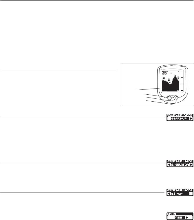
To turn on the display, press and release the POWER-MENU button. Press and hold
POWER-MENU until the display unit shuts down to power off.
Screen
Left Arrow Button
Power-Menu Button
Right Arrow Button
Start-Up in Fishing Mode
After pushing the POWER-MENU button to turn on the unit, you will see the Start-Up screen.
The Start-Up screen will disappear automatically after two seconds have passed, without further action from you. In Fishing mode, the screen will either display Waiting for Sonar or Received Sonar.
When you have powered on the unit and have cast the RSS into the water, returned sonar data will start to be displayed on the LCD. See Understanding the On-Screen Images for more information.
Start-Up in Simulator Mode
After pushing the POWER-MENU button to turn on the unit, and the |Start-Up screen is displayed, quickly press
the Right Cursor Button to enter Simulator mode. Once you are in Simulator mode, the screen will show Simulate, and after two seconds, the screen will start to display simulated data. To exit Simulator mode, you must power down the unit.
Start-Up in Set-Up Mode
Your RF10 comes with a Set-Up mode to allow you to choose the units of depth (Meters, Feet or Fathoms). After
pushing the POWER-MENU button to turn on the unit, and the Start-Up screen is displayed, quickly press the Right Cursor Button twice to enter Set-Up mode.
Within a few seconds, the screen will change to display the Units menu, which defaults to Feet or Meters, depending on your model number. By pressing the Right Cursor Button, you can choose Feet, Meters or Fathoms. You must power down the unit to save your selection, then power it back on again to enter normal Fishing mode.

Understanding the On-Screen Images
The SmartCast displays received underwater sonar information in an easy to understand format. The top of the display corresponds to the water surface, and the bottom of the display corresponds to the selected Depth Range (see Depth Range). The display varies as the area under the RSS changes. Reeling in the RSS at a slow and steady rate will allow you to graph the bottom for structure, detail and fish. Digital readouts provide precise information for bottom contour, depth and fish locations below the RSS.
If you are using SmartCast to graph an area, terrain and bottom composition varia-
tions are displayed on-screen. Fish and bait fish are displayed when detected. Underwater conditions vary greatly, so some experience and interpretation is need-
ed to realize all the benefits of the SmartCast – use the picture above as a guide to
the most common conditions and practice using the SmartCast over known bottom types.
Menu Features
A simple menu system accesses the adjustable features of the SmartCast. To acti-
vate the menu system, press the POWER-MENU button; the first time you do this after power up, the Sensitivity menu will appear. Once the SmartCast has been powered on, pressing the POWER-MENU button will display the last menu viewed.
Press POWER-MENU repeatedly to access other SmartCast menu choices, one at a time. When a menu choice is on the display, use the RIGHT and LEFT Cursor but-
tons to adjust the menu settings. Menus are automatically removed from the screen after several seconds.
NOTE: Menu settings are not saved in memory. All settings return to factory defaults when the SmartCast is turned off.
Light
Press POWER-MENU until the LIGHT menu appears. Select either OFF or ON to activate the backlight. Default = OFF
NOTE: Continuous backlight operation significantly decreases the SmartCast’s battery life by as much as 60%.
Sensitivity
Press POWER-MENU until the Sens-itivity menu appears. Select a higher number to show smaller sonar returns on-
screen, or a lower number to remove clutter from the screen. Adjusting Sensitivity also affects how sonar returns not attached to the bottom are identified as Fish ID Symbols. Larger returns will be shown as fish at a lower setting. Increasing Sensitivity selects smaller returns to be identified as fish. Sensitivity settings range from 1 to 5. Default = 3
Depth Range
Press POWER-MENU until the Depth Range menu appears. Select AUTO to have the SmartCast automatically set the Depth
Range. Select 10,15, 20, 30, 60 or 100 feet to set a manual depth range. This locks the depth range to a specific setting. Default = AUTO
NOTE: In manual operation, if the water depth is greater than the depth range setting, the bottom will not be visible on-screen. Select AUTO to return to automatic operation.
Depth Scale changes or signal loss will cause lines with missing detail and/or abrupt changes in the graphed bottom. When the Depth range is set to AUTO, the depth is set to keep the bottom in the lower third of the screen. The screen image jump shown here is due to an automatic change in depth. New returns graphed at a different scale will not match up with the historic data already graphed at a higher or lower scale. Vertical lines can also occur as the radio signal from the RSS is lost and then regained in rough water conditions.
Depth Change or temporary signal loss 
Graphed sonar history at a different range setting
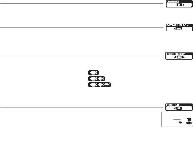
Channel
Press POWER-MENU until the CHANNEL menu appears. Select either A or B to match your RSS. See Channel A and B RSS Units. Default = Channel A
Bottom Black
Press POWER-MENU until the BOTTOM BLACK menu appears. Select OFF to gain bottom hardness information by 


 viewing second returns. For a high contrast display that is easy to view from a distance, leave the view setting on Bottom Black. Default = ON
Fish Alarm
Press POWER-MENU until the FISH ALARM menu appears. Select OFF for no fish alarm, or one of the following symbols to set the alarm point and turn it on. Default = OFF
• Alarms on big fish only
• Alarms on big and medium fish only
• Alarms on all fish
Fish ID+ must be set to ON for Fish Alarm to work.
Fish ID+
Press POWER-MENU until the FISH ID+ menu appears. Select either OFF to view “raw” sonar returns, or ON to take advantage of SmartCast’s ability to identify sonar returns that are determined to be fish. The sensitivity setting also affects the definition of sonar returns as fish (see Sensitivity). Some fish symbols will show the depth of the fish above the fish symbol. Fish Alarm does not sound if Fish ID+ is turned off. Default = ON
Fish ID
Raw Sonar
Channel A and B RSS Units
There are two versions of the RSS that are available at your local tackle dealer, major outdoor retailers, or at the website www.humminbird.com: Channel A and Channel B.
The Channel A RSS unit (RF40A) comes standard with your SmartCast product. You also have the option to purchase additional Channel A or Channel B RSS. When using the A or B version of the RSS, make sure to select the appropriate channel in the CHANNEL menu.
The A&B Channel Option gives you the flexibility to use a different type of RSS than the one you are currently using if another angler is using a SmartCast product within 100 feet of your SmartCast. If you have a Channel B RSS, you will need to set the channel to B each time you power up the SmartCast. Two Channel A or two Channel B RSS units in the water within 100 feet of the display will cause RF interference that prevents the product from functioning properly, resulting in fluctuating depth readings and excessive clutter on the screen. If you use a Channel B RSS while another angler is using an Channel A RSS or vice versa, the interference will be reduced but not completely eliminated.
NOTE: RSS units, regardless of Channel, either in close proximity to each other or to other sonar devices (closer than 40 feet) can also experience or cause sonar interference, which may result in erratic depth readings.

Maintenance
Your SmartCast is designed to provide years of trouble-free operation with virtually no maintenance. Follow these simple procedures to ensure your SmartCast continues to deliver top performance.
After using the RSS in salt water, wipe the affected surfaces with a cloth dampened with fresh water. The RSS Wet SwitchTM pins must be rinsed with fresh water after exposure to salt water to prevent corrosion.
If the SmartCast comes into contact with salt spray, wipe the affected surfaces with a cloth dampened with fresh water. When cleaning the LCD protective lens, use a chamois and non-abrasive, mild cleaner. Do not wipe while dirt or grease is on the lens. Be careful to avoid scratching the lens. Do not use a chemical glass cleaner on the lens, as this may cause it to crack.
If your RSS remains out of the water for a long period of time, it may take some time to wet it when returned to the water. Small air bubbles can cling to the surface of the RSS and interfere with proper operation. Wipe the face of the RSS with a wet cloth to remove them.
If sonar performance becomes weak (i.e., there are bottom gaps or "0" depth readings) the bottom of the RSS needs to be cleaned with a drop or two of a 5 to 10 percent solution of liquid dishwashing detergent and water. Use approximately one tablespoon detergent to 8 ounces of water to remove oils from the face of the RSS, then wipe with a damp cloth.
Never leave the SmartCast product in a closed car or trunk - the extremely high temperatures generated in hot weather can damage the electronics.
Replacement Battery Power Cables
You will not have to install the battery power cable before first use, but may need to replace it should it become corroded after prolonged usage in a marine environment. Order replacement cables at www.humminbird.com.
Troubleshooting
Do not attempt to repair the SmartCast or RSS yourself. There are no user serviceable parts inside, and special tools and techniques are required for assembly to ensure the waterproof integrity of the housings. Repairs should be performed only by authorized Humminbird technicians.
Many requests for repair received by Humminbird involve units that do not actually need repair. These units are returned “no problem found.” If you have a problem with your SmartCast, use the following troubleshooting guide before calling the Customer Resource Center or sending your unit in for repair.
NOTE: Retrieving the RSS too rapidly, or the repetitive rocking motion of rough water, can result in loss or distortion of the bottom picture. This will cause intermittent screen display. For best bottom detail, perform a smooth and slow reel-in with constant speed and the rod tip up (holding the rod tip low or using a heavy line may cause the RSS to submerge and momentarily lose radio contact). The RSS has a maximum transmit range of 100 feet (30 meters). If the unit is cast or drifts more than 100 feet away from the receiver, the signal may be inconsistent or lost. Raising the SmartCast slightly above ground level will also increase signal capture.
1. The SmartCast loses signal.
If the SmartCast is not able to get an RF signal from the RSS, the display will stop updating (the screen will freeze) and the SmartCast screen will be displayed after several seconds. Whenever reception is lost or the RSS emerges from the water for more than a few seconds, the SmartCast screen will be displayed until the RSS is placed back in the water and reception is regained.
•The SmartCast system is a line-of-sight wireless product. If objects are placed between the RSS and the SmartCast, the reception may be lost.
•The SmartCast depth range is 2 to 100 feet (0.6 to 30 meters). Erratic readings may occur in water that is shallower than 2 feet. In addition, because of the nature of sonar, this product is not intended for use in swimming pools or small enclosed bodies of water.
•Reeling the RSS too fast can cause loss of signal and the screen will freeze
 Loading...