


RX1290 Multi-Format Receiver
Software Version 3.0.0 (and later)
REFERENCE GUIDE
EN/LZT 790 0003/2 R1A

Preliminary Pages
ENGLISH (UK) - READ THIS FIRST!
If you do not understand the contents of this manual. DO NOT OPERATE THIS EQUIPMENT. Also, translation into any EC official language of this manual can be made available, at your cost.
SVENSKA - LÄS DETTA FÖRST!
Om Ni inte förstår informationen i denna handbok. ARBETA DÅ INTE MED DENNA UTRUSTNING. En översättning till detta språk av denna handbok kan också anskaffas, på Er bekostnad.
PORTUGUÊS - LEIA O TEXTO ABAIXO ANTES DE MAIS NADA!
Se não compreende o texto deste manual. NÃO UTILIZE O EQUIPAMENTO. O utilizador poderá também obter uma tradução do manual para o português à própria custa.
FRANÇAIS - AVANT TOUT, LISEZ CE QUI SUIT!
Si vous ne comprenez pas les instructions contenues dans ce manuel. NE FAITES PAS FONCTIONNER CET APPAREIL. En outre, nous pouvons vous proposer, à vos frais, une version française de ce manuel.
DEUTSCH - LESEN SIE ZUERST DIESEN HINWEIS!
Sollte Ihnen der Inhalf dieses Handbuches nicht klar verständlich sein, dann. BEDIENEN SIE DIESE GERÄTE NICHT! Eine Übersetzung des Handbuches in diese Sprache ist gegen Berechnung lieferbar.
ESPAÑOL - LEA ESTE AVISO PRIMERO!
Si no entiende el contenido de este manual. NO OPERE ESTE EQUIPO. Podemos asimismo suministrarle una traducción de este manual al (idioma) previo pago de una cantidad adicional que deberá abonar usted mismo.
ITALIANO - LEGGERE QUESTO AVVISO PER PRIMO!
Se non si capisce il contenuto del presente manuale. NON UTILIZZARE L’APPARECCHIATURA.. È anche disponibile la versione italiana di questo manuale, ma il costo è a carico dell’utente.
NEDERLANDS - LEES DIT EERST!
Als u de inhoud van deze handleiding niet begrijpt. STEL DEZE APPARATUUR DAN NIET IN WERKING. U kunt tevens, op eigen kosten, een vertaling van deze handleiding krijgen.
SUOMI - LUE ENNEN KÄYTTÖÄ!
Jos et ymmärrä käsikirjan sisältöä. ÄLÄ KÄYTÄ LAITETTA. Käsikirja voidaan myös suomentaa asiakkaan kustannuksella.
DANSK - LÆS DETTE FØRST!
Udstyret må ikke betjenes. MEDMINDRE DE TIL FULDE FORSTÅR INDHOLDET AF DENNE HÅNDBOG. Vi kan også for Deres regning levere en dansk oversættelse af denne håndbog.
ΕΛΛΗΝΙΚΑ - ΔΙΑΒΑΣΤΕ ΠΡΩΤΑ ΑΥΤΟ!
Αν δεν καταλάβετε το περιεχόμενο αυτού του βοηθήματος/εγχειριδίου. ΜΗΝ ΛΕΙΤΟΥΡΓΗΣΕΤΕ ΑΥΤΟΝ ΤΟΝ ΕΞΟΠΛΙΣΜΟ. Επίσης, αυτό το εγχειρίδιο είναι διαθέσιμο σε μετάφραση σε αυτή τη γλώσσα και μπορείτε να το αγοράσετε.
Copyright
© Copyright Ericsson AB 2011. All rights reserved.
Disclaimer
No part of this document may be reproduced in any form without the written permission of the copyright owner.
The contents of this document are subject to revision without notice due to continued progress in methodology, design and manufacturing. Ericsson shall have no liability for any error or damage of any kind resulting from the use of this document.
ii |
EN/LZT 790 0003/2 R1A 2011-06-06 |
Preliminary Pages
Contents
Chapter 1: Introduction
This chapter identifies the equipment versions covered by this Reference Guide; describes the purpose of the equipment in a typical system; provides a summary of its main features; identifies the controls, indicators and connectors.
Chapter 2: Installing the Equipment
This chapter provides a guide to the suitability of an installation; gives detailed procedures for the preparation, installation and configuration of the equipment including important safety information; provides pin-out details of the external connectors; and details the power-up/-down procedures.
Chapter 3: Operating the Equipment Locally
This chapter provides a guide to using the Front Panel LCD interface and details the setting-up, configuration and operating procedures.
Chapter 4: Operating the Equipment Remotely
This chapter provides a guide to configuring and preparing the unit for remote operation.
Chapter 5: Alarms
This chapter provides a guide to configuring the alarm interface.
Chapter 6: Options
This chapter describes the available hardware and software options for the equipment.
Chapter 7: Preventive Maintenance and Fault-finding
This chapter details routine maintenance tasks to be performed; provides general servicing advice, and information regarding warranty and maintenance; provides general fault-finding information for other types of problem which may be encountered.
Annex A: Glossary
Annex B: Technical Specification
Annex C: Menus
Annex D: Annex A: Glossary
Annex E: Factory Defaults
EN/LZT 790 0003/2 R1A 2011-06-06 |
iii |
Preliminary Pages
Introduction
This Reference Guide provides instructions and information for the installation and operation of the RX1290 Multi-Format Receiver.
This Reference Guide should be kept in a safe place for reference for the life of the equipment. It is not intended that this Reference Guide will be amended by the issue of individual pages. Any revision will be by a complete reissue. Further copies of this Reference Guide can be ordered from the address listed in Customer Services. If passing the equipment to a third party, also pass the relevant documentation.
Revision History
Issues of this Reference Guide are listed below:
Issue |
Date |
Software Version |
Comments |
|
|
|
|
1 |
Jul 2006 |
1.0.0 |
Initial release. |
|
|
|
|
2 |
Oct 2006 |
1.0.0 |
Updates to Annex B Technical Specification |
|
|
|
Product name also corrected. |
|
|
|
|
3 |
Mar 2007 |
2.0.0 |
G.703 and IP Options added.. |
|
|
|
|
4 |
Jan 2008 |
3.0.0 |
Maintenance release. |
|
|
|
|
5 |
May 2008 |
3.0.0 |
References to New IP Card added. |
|
|
|
|
A |
June 2011 |
3.0.0 |
Allocation of Ericsson Number Identity and |
|
|
|
re-brand completion. |
|
|
|
|
Associated Documents
The following manuals/guides are also associated with this equipment:
Ericsson Document Identity |
Original Document |
Title |
|
Number |
|
|
|
|
1/1424-EN/LZT 790 0003 Uen A |
ST.US.E10228 |
RX1290 User Guide |
|
|
|
1424-EN/LZT 790 0003 Uen A |
ST.TS.E10288 |
RX1290 RCP |
|
|
|
Trademarks
All best endeavors have been made to acknowledge registered trademarks and trademarks used throughout this Reference Guide. Any notified omissions will be rectified in the next issue of this Reference Guide. Some trademarks may be registered in some jurisdictions but not in others.
Registered trademarks and trademarks used are acknowledged below and marked with their respective symbols. However, they are not marked within the text of this Reference Guide.
iv |
EN/LZT 790 0003/2 R1A 2011-06-06 |

|
Preliminary Pages |
Registered Trademarks |
|
Ethernet® |
Registered trademark of Xerox Corporation. |
Dolby®/AC-3® |
Registered trademarks of Dolby Laboratories Licensing |
|
Corporation. |
Trademarks |
|
Alteia™ |
Trademark of Ericsson AB. |
Macrovision |
|
This product incorporates copyright protection technology that is protected by U.S. patents and other intellectual property rights. Use of this copyright protection technology must be authorized by Macrovision Corporation, and is intended for home and other limited viewing uses only unless authorized by Macrovision. Reverse engineering or disassembly is prohibited.
Warnings, Cautions and Notes
Heed Warnings
All warnings on the product and in the operating instructions should be adhered to. The manufacturer cannot be held responsible for injuries or damage where warnings and cautions have been ignored or taken lightly.
Read Instructions
All the safety and operating instructions should be read before this product is operated.
Follow Instructions
All operating and use instructions should be followed.
Retain Instructions
The safety and operating instructions should be retained for future reference.
Warning!
Warnings give information which, if strictly observed, will prevent personal injury or death, or damage to property or the environment. They are highlighted for emphasis, as in this example, and are placed immediately preceding the point at which the reader requires them.
EN/LZT 790 0003/2 R1A 2011-06-06 |
v |

Preliminary Pages
Caution!
Cautions give information which, if strictly followed, will prevent damage to equipment or other goods. They are highlighted for emphasis, as in this example, and are placed immediately preceding the point at which the reader requires them.
Note: Notes provide supplementary information. They are highlighted for emphasis, as in this example, and are placed immediately after the relevant text.
EMC Compliance
This equipment is certified to the EMC requirements detailed in Annex B, Technical Specification. To maintain this certification, only use the leads supplied or if in doubt contact Customer Services.
Contact Information
Support Services
Our primary objective is to provide first class customer care that is tailored to your specific business and operational requirements. All levels are supported by one or more service performance reviews to ensure the perfect partnership between Ericsson and your business.
Warranty
All Ericsson products and systems are designed and built to the highest standards and are covered under a comprehensive 12 month warranty.
Levels of Continuing Ericsson Service Support
For standalone equipment, then Ericsson BASIC Essential support is the value for money choice for you. BASIC provides you with year-by-year Service long after the warranty has expired.
Call Ericsson Sales for more details.
vi |
EN/LZT 790 0003/2 R1A 2011-06-06 |
|
|
|
|
|
Preliminary Pages |
Customer Services |
|
|
|
|
|
Europe, Middle East |
Tel: |
+44 |
(0) 23 8048 4455 |
|
|
and Africa |
Fax: |
+44 |
(0) 23 8048 4467 |
|
|
|
Email: |
tvsupportemea@ericsson.com |
|
||
Americas |
Tel: |
+888 |
671 1268 |
US and Canada |
|
|
Tel: |
+678 |
812 6255 |
International |
|
|
Fax: |
+678 |
812 6262 |
Compression |
|
|
Email: |
tvsupportamericas@ericsson.com |
|||
|
Email: |
tvsupport@ericsson.com |
Software Support Centre |
||
China |
Tel: |
+86 |
10 8476 8676 |
Beijing |
|
|
Fax: |
+86 |
10 8476 7741 |
Beijing |
|
|
Tel: |
+852 |
2590 2388 |
Hong Kong |
|
|
Fax: |
+852 |
2590 9550 |
Hong Kong |
|
|
Email: |
tvsupportapac@ericsson.com |
|
||
Australia and New |
Tel: |
+612 |
(0) 9111 4027 |
|
|
Zealand |
Fax: |
+612 |
(0) 9111 4949 |
|
|
|
Email: tvsupportanz@ericsson.com |
|
|||
Internet Address |
www.ericsson.com |
|
|||
Technical Training
Ericsson provides a wide range of training courses on the operation and maintenance of our products and on their supporting technologies. Ericsson can provide both regularly scheduled courses and training tailored to individual needs. Courses can be run either at your premises or at one of our dedicated training facilities.
International |
Tel: |
+44 (0) 23 8048 4229 |
|
Fax: |
+44 (0) 23 8048 4161 |
|
Email: |
tvglobaltraining@ericsson.com |
Customer Services and Technical Training Postal Address
Ericsson
Unit 2
Strategic Park
Comines Way
Hedge End
Southampton
Hampshire
SO30 4DA
United Kingdom
EN/LZT 790 0003/2 R1A 2011-06-06 |
vii |
Preliminary Pages
Return of Equipment
If you need to return equipment for repair please contact your local Ericsson
Customer Services Department.
Please refer to the Customer Services Contact Information on Page vii
You will then be directed to return the faulty equipment to a repair centre with the appropriate facilities for that equipment. A tracking number will be issued that should be used if you need to enquire about the progress of the repair. The equipment should be properly packed and the tracking number should be clearly marked on the outside of the packaging.
Technical Publications
If you need to contact Ericsson Technical Publications regarding this publication, e-mail: tvtechpubs@ericsson.com.
viii |
EN/LZT 790 0003/2 R1A 2011-06-06 |

Introduction
Chapter 1
Contents
1.1 |
Scope of This Reference Guide ........................................................... |
1-3 |
1.1.1 |
Who Should Use This Reference Guide............................................... |
1-3 |
1.1.2 |
What Equipment is Covered by This Reference Guide ........................ |
1-3 |
1.1.2.1 |
The Equipment Models......................................................................... |
1-3 |
1.1.2.2 |
Software Version .................................................................................. |
1-5 |
1.2 |
Summary of Features ........................................................................... |
1-5 |
1.2.1 |
Main Features....................................................................................... |
1-5 |
1.2.2 |
Inputs.................................................................................................... |
1-7 |
1.2.2.1 |
ASI Input (Decoder).............................................................................. |
1-7 |
1.2.2.2 |
Remote Control .................................................................................... |
1-7 |
1.2.2.3 |
DVB-S / DVB-S2 L-Band Inputs (Satellite Receivers) (Option) ............ |
1-7 |
1.2.2.4 |
TTV G.703 DS3 and E3 Input (Telco Receivers) (Option).................... |
1-7 |
1.2.2.5 |
IP Input (Telco Receivers) (Option) ...................................................... |
1-7 |
1.2.2.6 |
Frame Synchronization......................................................................... |
1-7 |
1.2.3 |
Outputs ................................................................................................. |
1-7 |
1.2.3.1 |
Transport Stream Outputs .................................................................... |
1-7 |
1.2.3.2 |
Video Outputs....................................................................................... |
1-7 |
1.2.3.3 |
Audio Outputs....................................................................................... |
1-7 |
1.2.3.4 |
Data Output .......................................................................................... |
1-8 |
1.2.3.5 |
Alarm Output ........................................................................................ |
1-8 |
1.3 |
The Satellite Receiver .......................................................................... |
1-8 |
1.3.1 |
Typical Satellite System ....................................................................... |
1-8 |
1.3.2 |
Input Connections................................................................................. |
1-9 |
1.3.3 |
What the Satellite Receiver Does......................................................... |
1-9 |
1.4 |
The Telco Receiver/Decoder.............................................................. |
1-10 |
1.4.1 |
Typical Decoder System..................................................................... |
1-10 |
1.4.2 |
What the Decoder Does ..................................................................... |
1-10 |
1.5 |
Control Modes .................................................................................... |
1-11 |
1.5.1 |
Introduction......................................................................................... |
1-11 |
1.5.2 |
Front Panel (Local) Modes ................................................................. |
1-11 |
1.6 |
Guided Tour........................................................................................ |
1-12 |
1.6.1 |
Construction ....................................................................................... |
1-12 |
1.6.2 |
Front Panel Controls........................................................................... |
1-12 |
1.6.3 |
Front Panel LEDs ............................................................................... |
1-12 |
1.6.4 |
Rear Panel.......................................................................................... |
1-13 |
EN/LZT 790 0003/2 R1A |
1-1 |
Introduction
List of Figures |
|
|
Figure 1.1 |
Front View of a RX1290 Multi-Format Receiver |
................................... 1-3 |
Figure 1.2 |
Typical Satellite Compression System ................................................. |
1-8 |
Figure 1.3 |
What the Satellite Receiver Does......................................................... |
1-9 |
Figure 1.4 |
Typical Compression System............................................................. |
1-10 |
Figure 1.5 |
Role of the Decoder ........................................................................... |
1-11 |
Figure 1.6 |
Front Panel States ............................................................................. |
1-11 |
Figure 1.7 |
Front Panel Controls .......................................................................... |
1-12 |
List of Tables |
|
|
Table 1.1 |
Equipment Model Descriptions............................................................. |
1-3 |
Table 1.2 |
Hardware Options ................................................................................ |
1-4 |
Table 1.3 |
Software Options.................................................................................. |
1-4 |
1-2 |
EN/LZT 790 0003/2 R1A |
Introduction
1.1Scope of This Reference Guide
1.1.1Who Should Use This Reference Guide
This Reference Guide is written for operators/users of the RX1290 Multi-Format Receiver. It describes the unit’s functions and operation. The Reference Guide is written to assist in the installation and day-to-day care and operation of the unit.
Maintenance information requiring the covers to be removed is not included.
Warning!
Do not remove the covers of this equipment. Hazardous voltages are present within this equipment and may be exposed if the covers are removed. Only Ericsson television trained and approved service engineers are permitted to service this equipment.
Caution!
Unauthorized maintenance or the use of non-approved replacements may affect the equipment specification and invalidate any warranties.
1.1.2What Equipment is Covered by This Reference Guide
1.1.2.1The Equipment Models
Ericsson is introducing an improved ordering system for its television products. New part numbers are being introduced to support this new system. The tables below shows the new part numbers used for ordering and supply of the product and its options. The Multi-Format Receiver described in this Reference Guide is the base model.
Figure 1.1 Front View of a RX1290 Multi-Format Receiver
Table 1.1 Equipment Model Descriptions
Marketing Code |
Price Object |
Supply Object |
Description |
|
Number |
Number |
|
|
|
|
|
RX1290/BAS |
FAZ 101 0116/1 |
KDU 137 642/1 |
Decoder with integrated Common Interface |
|
|
|
CAM reader, AC voltage input. SD MPEG-2 |
|
|
|
4:2:0, SD MPEG-2 4:2:2, HD MPEG-2 4:2:0 |
|
|
|
video decode only. |
|
|
|
|
EN/LZT 790 0003/2 R1A |
1-3 |
Introduction
Table 1.2 |
Hardware Options |
|
|
|
Marketing Code |
Price Object |
Supply Object |
Description |
|
|
|
Number |
Number |
|
RX1290/HWO/DVBS2 |
FAZ 101 0116/3 |
ROA 128 3800 |
DVBS2 I/P SAT DEMOD |
|
|
|
|
|
OPTION |
|
|
|
|
|
RX1290/HWO/DVBS2/IF/C |
FAZ 101 0116/5 |
ROA 128 3801 |
DVBS2 I/P SAT |
|
|
|
|
|
DEMOD+CONST O/P |
|
|
|
|
|
RX1290/HWO/IP/PROFEC |
FAZ 101 0116/8 |
ROA 128 3802 |
IP, PRO-MPEG INPUT |
|
|
|
|
|
OPTION |
|
|
|
|
|
RX1290/HWO/G703 |
FAZ 101 0116/6 |
ROA 128 3803 |
G.703 INPUT OPTION CARD |
|
|
|
|
|
|
RX1290/HWO/IP/GIGE |
FAZ 101 0116/7 |
ROA 128 3804 |
100/1000 BASE-T INPUT |
|
|
|
|
|
OPTION |
|
|
|
|
|
Table 1.3 |
Software Options |
|
|
|
|
|
|
|
|
Marketing Code |
Price Object |
Supply Object |
Description |
|
|
|
Number |
Number |
|
RX1290/SWO/MPEG2/HD/422 |
FAZ 101 0116/22 |
FAT 102 0205 |
MPEG-2 HD 4:2:2 LICENSE |
|
|
|
|
|
|
RX1290/SWO/MPEG4/SD |
FAZ 101 0116/24 |
FAT 102 0206 |
MPEG-4 SD 4:2:0 LICENSE |
|
|
|
|
|
|
RX1290/SWO/MPEG4/HD |
FAZ 101 0116/23 |
FAT 102 0207 |
MPEG-4 HD 4:2:0 LICENSE |
|
|
|
|
|
|
RX1290/SWO/DIR5 |
FAZ 101 0116/14 |
FAT 102 0208 |
DIRECTOR V5 LICENSE |
|
|
|
|
|
|
RX1290/SWO/AC3 |
FAZ 101 0116/11 |
FAT 102 0209 |
DOLBY AC3 LICENSE |
|
|
|
|
|
|
RX1290/SWO/DVBS2/QPSK |
FAZ 101 0116/18 |
FAT 102 0210 |
DVB-S2 QPSK LICENSE |
|
|
|
|
|
|
RX1290/SWO/DVBS2/8PSK |
FAZ 101 0116/16 |
FAT 102 0211 |
DVB-S2 8PSK LICENSE |
|
|
|
|
|
|
RX1290/SWO/DVBS2/LSYM |
FAZ 101 0116/17 |
FAT 102 0212 |
DVB-S2 LOW SYMBOL RATE |
|
|
|
|
|
LICENSE |
|
|
|
|
|
RX1290/SWO/DVBS2/16APSK |
FAZ 101 0116/15 |
FAT 102 0213 |
DVB-S2 16APSK LICENSE |
|
|
|
|
|
|
RX1290/SWO/CI |
FAZ 101 0116/12 |
FAT 102 0214 |
COMMON INTERFACE |
|
|
|
|
|
LICENSE |
|
|
|
|
|
RX1290/SWO/RAS |
FAZ 101 0116/28 |
FAT 102 0215 |
RAS LICENSE |
|
|
|
|
|
|
RX1290/SWO/PROV/LOCK |
FAZ 101 0116/26 |
FAT 102 0216 |
PROVIDER LOCK LICENSE |
|
|
|
|
|
|
RX1290/SWO/IP/PROMPEG |
FAZ 101 0116/20 |
FAT 102 0217 |
PRO-MPEG IP LICENSE |
|
|
|
|
|
|
RX1290/SWO/UPCONV |
FAZ 101 0116/29 |
FAT 102 0218 |
UPCONVERSION LICENSE |
|
|
|
|
|
|
RX1290/SWO/DCONV |
FAZ 101 0116/13 |
FAT 102 0219 |
DOWN CONVERSION |
|
|
|
|
|
LICENSE |
|
|
|
|
|
RX1290/SWO/AAC |
FAZ 101 0116/10 |
FAT 102 0220 |
AAC AUDIO LICENSE |
|
|
|
|
|
|
RX1290/SWO/PW |
FAZ 101 0116/27 |
FAT 102 0222 |
PASSWORD PROTECTION |
|
|
|
|
|
LICENSE |
|
|
|
|
|
1-4 |
EN/LZT 790 0003/2 R1A |

|
|
|
Introduction |
|
|
|
|
Marketing Code |
Price Object |
Supply Object |
Description |
|
Number |
Number |
|
RX1290/SWO/LDELAY |
FAZ 101 0116/21 |
FAT 102 0223 |
LOW LATENCY DECODE |
|
|
|
MODE (4:2:0 ONLY) |
|
|
|
|
RX1290/SWO/HSETHER |
FAZ 101 0116/19 |
FAT 102 0224 |
HIGH SPEED DATA PIPING |
|
|
|
LICENSE |
|
|
|
|
RX1290/SWO/PAA |
FAZ 101 0116/25 |
FAT 102 0229 |
QUAD PHASE ALIGNED |
|
|
|
MPEG-1 LAYER 2 AUDIO |
|
|
|
|
RX1290/SWO/4AUD |
FAZ 101 0116/9 |
FAT 102 0221 |
DIGITAL AUDIO 3&4 |
|
|
|
LICENSE |
|
|
|
|
RX1290/SWO/EBU/3.6.2 |
FAZ 101 0116/34 |
FAT 102 0227 |
RX1290 SW 3.6.2 FOR EBU |
|
|
|
|
RX1290/SWO/UPG/MP4SD/MP4H |
FAZ 101 0116/31 |
FAT 102 0225 |
UPGRADE FROM MPEG4 SD |
|
|
|
TO HD |
|
|
|
|
RX1290/SWO/UPG/MP2422/MP4H |
FAZ 101 0116/30 |
FAT 102 0226 |
UPGRADE FROM MPEG-2 |
|
|
|
HD 4:2:2 TO MPEG-4 HD |
|
|
|
|
1.1.2.2Software Version
This Reference Guide covers the functions of software version 3.0.0 and later.
To verify the installed version access the Systems Menu (Menu 7.2.1). The menus are described in Annex C, Menus.
1.2Summary of Features
1.2.1Main Features
The Multi-Format Receiver is fully compliant with the appropriate sections of the MPEG-21, DVB-S2 and MPEG-4 AVC3 specifications and offers the following features:
•Front Panel Controls and Indications:
-A vertical split two line x 40 character back-lit dot matrix LCD display with pushbuttons for Up, Down, Left, Right, Edit, and Save to provide information and operator choice entry.
-LEDs to indicate lock and general alarm conditions.
•Service Selection:
-Chosen from a menu list of available Services carried in the currently received Transport Stream.
1Moving Pictures Expert Group: MPEG-2 specification ISO 13818.
2European Digital Video Broadcasting (DVB) Project. EN 300 421 Digital broadcasting systems for television, sound and data services: Framing structure, channel coding and modulation for the 11/12 GHz satellite service.
3ITU-T Recommendation and ISO/IEC 14496-10 (MPEG-4 AVC) Advanced Video Coding.
EN/LZT 790 0003/2 R1A |
1-5 |
Introduction
-Up to 40 preselected choices can be stored within the unit.
•Multiple Inputs (Satellite Receivers):
-L-band Satellite Receivers have four inputs.
•Video Decoding:
-MPEG 4:2:0 mode support.
-MPEG 4:2:2 mode support (MPEG-2 Only).
•Audio Decoding:
-Sampling rate 48 kHz.
-All MPEG-1 data rates.
-AAC decode.
-All Dolby Digital AC-3 data rates, decoded as a Dolby Stereo downmix.
-Dolby E pass-through.
-Linear uncompressed audio, data rates as defined by SMPTE 302M.
-DTS audio detection and pass-through.
•Data:
-Low Speed Data: RS-232 asynchronous (up to 38.4 kbps).
-High Speed Data: Ethernet Data-piping (up to 5 Mbps) (option).
•Transport Stream Output:
-ASI Transport Stream output with maximum data rate 160 Mbps.
•Remote Control:
-SNMP.
-RS-232 (Alteia protocol).
•Clock/Calendar:
-Available to coordinate universal and local time.
-Constantly updated when locked to a valid Transport Stream.
•Transport Stream Demultiplexing:
-Maximum capability is 160 Mbps, depending on CA in use and input frontend.
•Video Decoding:
-Maximum Video decoding capability of 90 Mbps.
•Audio:
-Audio embedding in the digital video output.
•VANC data support:
-Closed Captions.
-VITC.
-ARIB reference spec TR23.
•Frame Synchronization of video output to a composite analogue input.
•Local Control Methods:
1-6 |
EN/LZT 790 0003/2 R1A |
Introduction
-Front Panel User Interface.
1.2.2Inputs
1.2.2.1ASI Input (Decoder)
One BNC connector supporting both byte-mode and single packet burst mode.
1.2.2.2Remote Control
An RJ-45 Ethernet connector for connection to a PC or network switch to provide SNMP control.
1.2.2.3DVB-S / DVB-S2 L-Band Inputs (Satellite Receivers) (Option)
Four F-type connectors connect the L-band output of a suitable LNB either directly or via a suitable attenuator giving lightning and surge protection.
1.2.2.4TTV G.703 DS3 and E3 Input (Telco Receivers) (Option)
Equipped with a single BNC connector for receiving signals over a PDH Telco network.
1.2.2.5IP Input (Telco Receivers) (Option)
A single 10/100/1000BaseT RJ-45 connector for receiving signals over Ethernet
1.2.2.6Frame Synchronization
A BNC connector accepts a composite video input to which the video output timing can be synchronized.
1.2.3Outputs
1.2.3.1Transport Stream Outputs
•Up to three BNC connectors output ASI Transport Streams with a maximum data rate of 160 Mbps, depending on the CA in use and the input card front-end.
1.2.3.2Video Outputs
•One SVGA HD video output carried on a D-type connector for monitoring only.
•Three digital video outputs carried on BNC connectors (same connectors as ASI).
•One SD Analogue composite video output on BNC.
1.2.3.3Audio Outputs
•Two 9-way, D-type, male connectors each provide simultaneous analogue stereo and balanced digital audio output. The digital mode can be changed via the user interface.
EN/LZT 790 0003/2 R1A |
1-7 |
Introduction
•Four BNC connectors providing unbalanced audio output.
1.2.3.4Data Output
•RS-232 asynchronous low-speed data output carried on a 9-way, D-type, female connector.
•RJ-45 high speed data over Ethernet output (option).
1.2.3.5Alarm Output
A 9-way, D-type connector for interfacing to the alarm and failure monitoring within the Multi-Format Receiver. This includes a summary alarm signal that coincides with the general front-panel ALARM LED.
There is one relay for failure monitoring. The operator can define (using the Alarm Menu pages) which alarm conditions drive the relay. This is described in Chapter 5, Alarms and Annex C, Menus.
1.3The Satellite Receiver
1.3.1Typical Satellite System
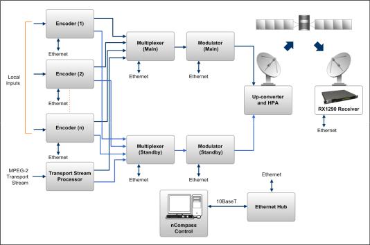
The Multi-Format Receiver is a component of the MPEG-4 AVC/MPEG-2/DVB compliant range of Ericsson's equipment. They are designed for use by broadcasters and distributors of video, audio and data Services over satellite.
Figure 1.2 Typical Satellite Compression System
1-8 |
EN/LZT 790 0003/2 R1A |
Introduction
1.3.2Input Connections
The Satellite Receiver interfaces directly to Low-Noise Block (LNB) and accepts an intermediate frequency (IF) input in the band 950 - 2150 MHz (L-band) for operation in the specified symbol-rate range (see Annex B, Technical Specification). The unit can provide dc power and polarization switching to the LNB.
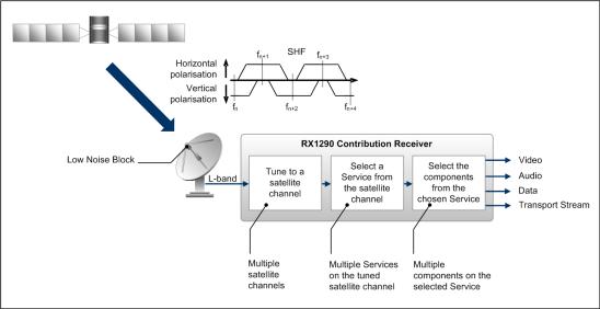
1.3.3What the Satellite Receiver Does
The Receiver can be tuned to a specified satellite channel frequency and polarization. The input is down-converted via a Low-Noise Block (LNB) to provide an L-band input to the Receiver. The front-end tuning is microprocessor controlled with a frequency synthesized local oscillator. A software tuning and acquisition algorithm resolves translation errors (mainly due to the LNB).
The signal is then passed to a demodulator that recovers the signal using softdecision decoding. The resulting stream is Reed-Solomon decoded and descrambled to provide inputs to the Decoder circuit. The received channel may contain multiple Services, therefore the Receiver’s demultiplexer is configured to select a single video Service and other audio/data components and present them at the output.
Figure 1.3 What the Satellite Receiver Does
EN/LZT 790 0003/2 R1A |
1-9 |
Introduction
1.4The Telco Receiver/Decoder
1.4.1Typical Decoder System
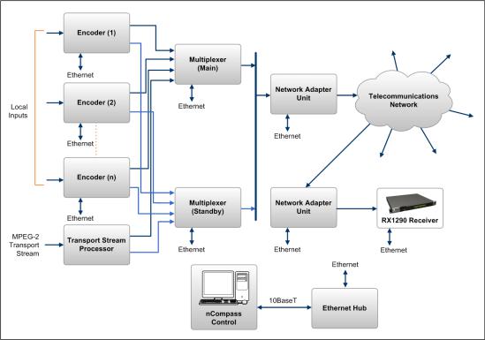
The Decoder is a component of Ericsson’s range of equipment. It is designed for use by broadcasters and distributors of video and audio Services. It can be used as a Transport Stream monitor or to decode signals received over a telecommunications network.
Figure 1.4 Typical Compression System
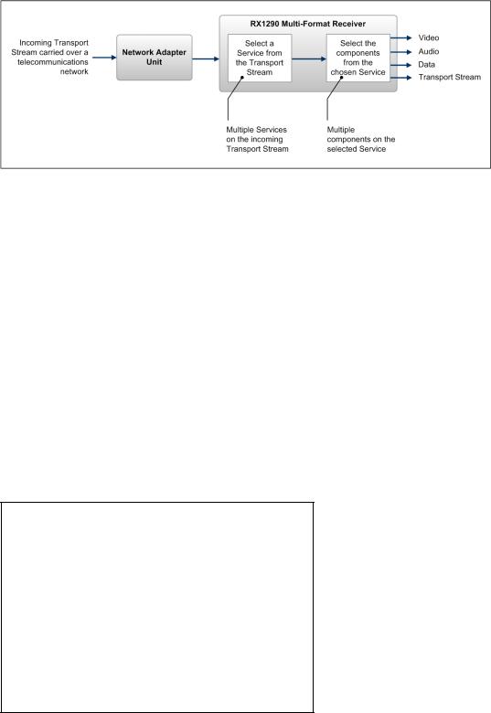
1.4.2What the Decoder Does
The ASI interface is used to present the Transport Stream in the format required by the internal Decoder circuitry. At this point, the operation of the unit is the same as the Satellite Receiver.
The Decoder can be used to receive an input signal from a Public Telecom Network via a Network Adapter Unit (NAU). No error correction is supported at the input of the unit so a level of Quality of Service should be negotiated with the Telecom Network Provider.
The Decoder is configured to select a single video Service and other audio/data components from the multiple Services on the incoming Transport Stream and present them at the output.
1-10 |
EN/LZT 790 0003/2 R1A |
Introduction
Figure 1.5 Role of the Decoder
1.5Control Modes
1.5.1Introduction
The Multi-Format Receiver is designed for unattended operation. Once set-up, the unit requires no further attention except to ensure the fans are working. There are up to three control modes associated with the Receiver (dependent upon options fitted). The unit remains in the chosen control mode until another mode is requested.
Note: Local (Front Panel) Control is the factory default if Director is not installed.
1.5.2Front Panel (Local) Modes
Operating the Multi-Format Receiver from the Front Panel is via two main operating modes: Navigate and Edit. See Section 3.3, Front Panel Operating Modes.
Timeout (5 minutes)
EDIT Off
EDIT |
NAVIGATE |
EDIT On
SAVE
Figure 1.6 Front Panel States
EN/LZT 790 0003/2 R1A |
1-11 |
Introduction
1.6Guided Tour
1.6.1Construction
The Multi-Format Receiver is constructed using a screened self-ventilated modular system. All operational inputs and outputs are via rear-panel connectors. The unit may be operated freestanding or mounted in a 19-inch rack.
1.6.2Front Panel Controls
The physical interface for the Front Panel consists of an alphanumeric LCD display, pushbuttons, and status LEDs that are used to set-up and monitor the unit. The general layout is shown in Figure 1.7. Information on the use of these controls is given in Chapter 3, Operating the Equipment Locally.
User input is via six pushbuttons comprising four cursor pushbuttons: Left, Right, Up, and Down; and two edit control pushbuttons: Edit and Save.
Each pushbutton has an integral green LED except Save, which has an integral red LED. When lit these LEDs indicate to the user which pushbutton is currently active.
Automatic repeat following an initial delay period is implemented for the Left, Right, Up, and Down pushbuttons in software.
ALARM LED |
LCD display |
Edit |
Left |
Up |
|
|
|
|
|
|
|
|
|
|
|
|
|
|
|
|
|
|
|
POWER LED |
Save |
Down Right |
Figure 1.7 Front Panel Controls
1.6.3Front Panel LEDs
Figure 1.7 shows the location of the LEDs on the front panel The LEDs indicate the Multi-Format Receiver status as follows:
The red ALARM LED is used to indicate a Multi-Format Receiver fault condition, e.g. a missing or faulty input signal. It should be off for correct operation, although it may be lit briefly during power up.
The green POWER LED is used to indicate that the Multi-Format Receiver is locked to a Transport Stream when lit, indicates correct conditions and correct system functioning.
1-12 |
EN/LZT 790 0003/2 R1A |
Introduction
1.6.4Rear Panel
Inputs and outputs to the unit are taken via the rear panel. Connector descriptions are given in Chapter 2, Installing the Equipment and Chapter 6, Options.
EN/LZT 790 0003/2 R1A |
1-13 |
Introduction
BLANK
1-14 |
EN/LZT 790 0003/2 R1A |

Installing the Equipment
Chapter 2
Contents
2.1 |
Read This First! .................................................................................... |
2-3 |
2.1.1 |
Handling ............................................................................................... |
2-3 |
2.1.2 |
Installing the Equipment ....................................................................... |
2-3 |
2.1.3 |
Lifting .................................................................................................... |
2-3 |
2.1.4 |
Site Requirements ................................................................................ |
2-3 |
2.1.4.1 |
Power Supplies..................................................................................... |
2-3 |
2.1.4.2 |
Environment ......................................................................................... |
2-3 |
2.1.4.3 |
Lightning Protection.............................................................................. |
2-3 |
2.2 |
Preliminary Checks............................................................................... |
2-4 |
2.2.1 |
Mechanical Inspection .......................................................................... |
2-4 |
2.2.2 |
Moving the Equipment Safely............................................................... |
2-4 |
2.3 |
Installing the Equipment ....................................................................... |
2-4 |
2.3.1 |
Fixing .................................................................................................... |
2-4 |
2.3.2 |
Ventilation............................................................................................. |
2-5 |
2.3.3 |
Openings in the Covers ........................................................................ |
2-5 |
2.3.3.1 |
Care in Positioning ............................................................................... |
2-5 |
2.3.3.2 |
Protection from Moisture ...................................................................... |
2-5 |
2.3.4 |
Installing Cables - Safety...................................................................... |
2-6 |
2.4 |
EMC Compliance Statements .............................................................. |
2-6 |
2.4.1 |
EN 55022/AS/NZS 3548....................................................................... |
2-6 |
2.4.2 |
FCC ...................................................................................................... |
2-6 |
2.5 |
AC Supply Operating Voltage and Fusing – Safety Information........... |
2-6 |
2.5.1 |
AC Power Supply ................................................................................. |
2-6 |
2.5.2 |
AC Power Supply Cord........................................................................ |
2-7 |
2.5.2.1 |
General................................................................................................. |
2-7 |
2.5.2.2 |
Wire Colors........................................................................................... |
2-7 |
2.5.3 |
Connecting the Equipment to the AC Power Supply ............................ |
2-8 |
2.6 |
Protective Earth/Technical Earth .......................................................... |
2-8 |
2.7 |
Signal Connections............................................................................... |
2-9 |
2.7.1 |
General................................................................................................. |
2-9 |
2.7.2 |
ASI/HD-SDI/SD-SDI OUT................................................................... |
2-11 |
2.7.3 |
CVBS.................................................................................................. |
2-11 |
2.7.4 |
Audio Outputs..................................................................................... |
2-11 |
2.7.5 |
SVGA Output (RGB HV)..................................................................... |
2-12 |
2.7.6 |
Frame Synchronization....................................................................... |
2-13 |
2.7.7 |
Ethernet .............................................................................................. |
2-14 |
2.7.8 |
ASI IN ................................................................................................. |
2-14 |
EN/LZT 790 0003/2 R1A |
2-1 |
Installing the Equipment
2.7.9 |
Alarm Connector and Relay ............................................................... |
2-15 |
2.7.10 |
RS-232 Low-speed Asynchronous Data Output ................................ |
2-15 |
2.7.11 |
Serial Remote Control........................................................................ |
2-16 |
2.8 |
Option Card Connectors..................................................................... |
2-16 |
List of Figures |
|
|
Figure 2.1 |
Air-flow Through the Equipment........................................................... |
2-5 |
Figure 2.2 |
AC Power Inlet Assembly..................................................................... |
2-7 |
Figure 2.3 |
Location of the Technical Earth............................................................ |
2-9 |
Figure 2.4 |
Typical Receiver Rear Panel................................................................ |
2-9 |
Figure 2.5 |
Signal Connections ............................................................................ |
2-10 |
List of Tables |
|
|
Table 2.1 |
Supply Cord Wiring Colors................................................................... |
2-7 |
Table 2.2 |
Non Standard Supply Cord Wire Colors............................................... |
2-8 |
Table 2.3 |
Digital Output Connector.................................................................... |
2-11 |
Table 2.4 |
Digital Output Connector.................................................................... |
2-11 |
Table 2.5 |
Analogue/Digital Audio Connectors.................................................... |
2-12 |
Table 2.6 |
Digital (Unbalanced) Audio Connectors ............................................. |
2-12 |
Table 2.7 |
SVGA Connector................................................................................ |
2-13 |
Table 2.8 |
Frame Sync Hi-Z Connector............................................................... |
2-14 |
Table 2.9 |
Ethernet Pin-outs ............................................................................... |
2-14 |
Table 2.10 |
Digital Input Connector....................................................................... |
2-14 |
Table 2.11 |
Alarm Connector ................................................................................ |
2-15 |
Table 2.12 |
RS-232 Low-speed Data.................................................................... |
2-15 |
Table 2.13 |
RS232/RS485 Remote Control .......................................................... |
2-16 |
2-2 |
EN/LZT 790 0003/2 R1A |

Installing the Equipment
2.1Read This First!
2.1.1Handling
The equipment must be handled and installed carefully and thoughtfully to prevent safety hazards and damage.
2.1.2Installing the Equipment
Ensure the personnel designated to fit the unit have the appropriate skills and knowledge. If in any doubt, contact Ericsson Customer Services (see Preliminary Pages for contact details).
Installation of the product should follow these instructions, and should only use installation accessories recommended by the manufacturers. When rack mounted, this equipment must have shelf supports as well as being fixed at the front panel.
Do not use this product as a support for any other equipment.
2.1.3Lifting
In some circumstances the unit might be awkward to lift. In which case, do not attempt to lift or move it without proper assistance or equipment. If in doubt, seek assistance.
2.1.4Site Requirements
2.1.4.1Power Supplies
See Annex B Technical Specification for a full specification.
2.1.4.2Environment
See Annex B, Technical Specification for a full specification.
Do not install this product in areas of high humidity or where there is danger of water ingress.
2.1.4.3Lightning Protection
Warning!
If the receiver has been subject to a lightning strike or power surge that has stopped it working, disconnect the power immediately. Do not re-apply power until it has been checked for safety. If in doubt contact Ericsson Customer Services.
EN/LZT 790 0003/2 R1A |
2-3 |

Installing the Equipment
Where appropriate, ensure this product has an adequate level of lightning protection. Alternatively, during a lightning storm or when it is left unattended and unused for long periods of time, unplug it from the supply outlet and disconnect the output equipment. This prevents damage to the product due to lightning and power line surges.
2.2Preliminary Checks
2.2.1Mechanical Inspection
Warning!
Removing the covers of this equipment may invalidate any warranties, cause a safety hazard or/and affect the EMC performance.
2.2.2Moving the Equipment Safely
Do not place this product on an unstable cart, stand, bracket, or table. The product may fall, causing serious injury and serious damage to the product. Use only with a cart, stand, bracket or table recommended by Ericsson.
An appliance and cart combination should be moved with care. Quick stops, excessive force, and uneven surfaces may cause the appliance and cart combination to overturn. Do not move or carry the equipment whilst it is still connected to the supply or other leads, is live, or is in operation.
2.3Installing the Equipment
2.3.1Fixing
The equipment is designed for fixed use only and has been shipped with fixing brackets suitable for a standard 19-inch rack. When installed in a rack, it should be secured using the fixing brackets. In addition, support shelves must be used to reduce the weight on the brackets. Ensure it is firmly and safely located and it has an adequate flow of free-air.
Slide the receiver onto the chassis supports and affix to the rack by means of an M6 x 18 mm panhead screw in each corner.
A freestanding unit should be installed on a secure horizontal surface where it is unlikely to be knocked or its connectors and leads disturbed.
2-4 |
EN/LZT 790 0003/2 R1A |
Installing the Equipment
2.3.2Ventilation
2.3.3Openings in the Covers
Side openings in the unit, as well as side-mounted cooling fans, are provided for ventilation. They ensure reliable operation of the product and protect it from overheating. The openings of the fans must not be blocked or covered.
Air is released through vents at this
side of the unit.
Fans are mounted on this side of the unit
Figure 2.1 Air-flow Through the Equipment
2.3.3.1Care in Positioning
Cautions!
The fans contained within this unit are not fitted with a dust/insect filter. Pay attention to the environment in which it is to be used.
Do not install equipment so that the air intake of one aligns with the outlet on another. Provide baffles and adequate spacing.
The equipment should never be placed near or over a radiator or other source of heat. It should not be placed in a built-in installation such as a rack unless proper ventilation is provided and the instructions have been adhered to.
Allow at least 40 mm free air-space at each side of the equipment to ensure adequate cooling. Racks containing stacked equipment may need to be forced aircooled to reduce the ambient temperature within the rack.
2.3.3.2Protection from Moisture
Do not install this equipment in areas of high humidity or where there is a danger of water ingress.
EN/LZT 790 0003/2 R1A |
2-5 |

Installing the Equipment
2.3.4Installing Cables - Safety
Power supply cables should be routed so that they are not likely to be walked on or pinched by items placed upon or against them. Pay particular attention to cables at plugs, convenience receptacles, and the point where they exit from the appliance.
Do not run AC power cables in the same duct as signal leads. Do not move or install equipment whilst it is still attached to the mains supply. Ensure safety and ESD precautions are observed whilst inter-connecting equipment.
2.4EMC Compliance Statements1
2.4.1EN 55022/AS/NZS 3548
This is a Class A product. In a domestic environment this product may cause radio interference in which case the user may be required to take adequate measures.
2.4.2FCC
This equipment has been tested and found to comply with the limits for a Class A digital device, pursuant to Part 15 of the FCC Rules. These limits are designed to provide reasonable protection against harmful interference when the equipment is operated in a commercial environment.
This equipment generates, uses and can radiate radio frequency energy and, if not installed and used in accordance with the Reference Guide, may cause harmful interference to radio communications. Operation of this equipment in a residential area is likely to cause harmful interference in which case the user will be required to correct the interference at his/her own expense.
2.5AC Supply Operating Voltage and Fusing – Safety Information
2.5.1AC Power Supply
The equipment operates from an wide-ranging mains power supply (100-240 V AC 50/60 Hz nominal) and is designed for use in ambient air temperature in the range 0°C to +50°C. There are no links etc. to be altered for operation from different supply voltages. The full Technical Specification is given in Annex B, Technical Specification.
1 The EMC information was correct at the time of manufacture. The EMC tests were performed with the Technical Earth attached.
2-6 |
EN/LZT 790 0003/2 R1A |

Installing the Equipment
Warning!
The RX1290 should only be operated from the type of power source indicated on the marking label. If you are not sure of the type to your business, consult your appliance dealer or local power company. Do not overload wall outlets and extension cords as this can result in a risk of fire or electric shock.
The RX1290 Receivers are not fitted with an AC power ON/OFF switch. Ensure the supply socket outlet is installed or located near the equipment so that it is accessible.
AC Power Inlet
Position of the fuse carrier
Figure 2.2 AC Power Inlet Assembly
Note: See Annex B, Technical Specification for fuse information.
2.5.2AC Power Supply Cord
2.5.2.1General
A two-meter power supply cord is supplied with this product. It is fitted with a molded plug suitable for the USA, UK or mainland Europe as advised at the time of ordering.
Note: The equipment is not fitted with an AC power supply ON/OFF switch. Ensure the socket-outlet supplying the equipment is installed near the equipment so that it is easily accessible.
2.5.2.2Wire Colors
The wires in the supply cord are colored as shown in Table 2.1.
Table 2.1 Supply Cord Wiring Colors
|
UK (BS 1363) |
EUROPE (CEE 7/7) |
USA (NEMA 5-15P) |
|
|
|
|
Earth: |
Green-and-yellow |
Green-and-yellow |
Green |
|
|
|
|
Neutral: |
Blue |
Blue |
White |
|
|
|
|
Live: |
Brown |
Brown |
Black |
|
|
|
|
EN/LZT 790 0003/2 R1A |
2-7 |

Installing the Equipment
If the colors do not correspond with the colored markings identifying the terminals in a locally supplied plug, proceed as in Table 2.2. The inclusion of Table 2.2 is for reference.
Table 2.2 Non Standard Supply Cord Wire Colors
Wire Color (UK) |
Action |
|
|
green-and-yellow |
...must be connected to the terminal in the plug which is marked |
|
with the letter E or the safety earth symbol or colored green or |
|
green-and-yellow. |
|
|
blue |
...must be connected to the terminal in the plug which is marked |
|
with the letter N or colored black. |
|
|
brown |
...must be connected to the terminal in the plug which is marked |
|
with the letter L or colored red. |
|
|
2.5.3Connecting the Equipment to the AC Power Supply
As there is no mains power switch fitted to this unit, ensure the local AC power supply is switched OFF before connecting the supply cord.
Connect the mains lead to the equipment and then to the local supply.
2.6Protective Earth/Technical Earth
Warning!
This unit must be correctly earthed through the molded plug supplied. If the local mains supply does not have an earth conductor do not connect the unit. Contact Ericsson Customer Services for advice.
Before connecting the unit to the supply, check the supply requirements in Annex B.
The terminal marked  at the rear panel is a Technical Earth. Its use is recommended. This is NOT a protective earth for electric shock protection. The terminal is provided to:
•Ensure all equipment chassis fixed within a rack are at the same technical earth potential. To do this, connect a wire between the Technical Earth terminal and a suitable point on the rack.
•Eliminate the migration of stray charges when connecting between equipment.
The Technical Earth provides a suitable connection between the equipment and the installation to give a low impedance path at normal operating frequencies.
2-8 |
EN/LZT 790 0003/2 R1A |
 Loading...