


OPERATOR’S MANUAL
SERIES 7000
COMPACT TRACTOR
Model Numbers 7530 7532
IMPORTANT:
READ SAFETY RULES AND INSTRUCTIONS CAREFULLY
CUB CADET LLC P.O. BOX 361131 CLEVELAND, OHIO 44136-0019 [www.cubcadet.com]
PRINTED IN U.S.A. |
FORM NO. 769-01060 |
|
(1/04) |

Off-Road Diesel Engine
Emission Control SystemWarranty Statement
Emission Related System Defect Warranty
Manufacturer Statement
Mitsubishi Heavy Industries, ltd. (MHI) will give a warranty condition, required by the
U.S. Environmental Protection Agency(EPA) and the California Air Resource Board(CA RB) to Original Equipment Manufacturers (OEMs) for small off-road engines purchased in 1997 and later which are used in U.S.A.
It is the OEMs responsibility to give the following warranty to the end-users for small off-road engines purchased in 1997 and later which are used in U.S.A.
The manufacturer of MHI small off-road engines has authorized equipment manufacturers to be th e direct contact for all warranty and service related questions and/or repairs. All inquiries should be directed to equipment manufacturers only.
Emission Control Warranty Statement
Applicable only to engines purchased in U.S.A. in 1997 and thereafter which are used in U.S.A. .
EPA emission control defects warranty statement – Your ( Customer) defects warranty rights and obligations:
EPA and Mitsubishi Heavy Industries, Ltd. are pleased to explain the emission control system warranty on your 1997 and later small off-road engine. In U.S.A., new small off-road engines must be designed, built and equipped to meet the EPA stringent anti-smog s tandards. Mitsubishi Heavy Industries, Ltd. must warrant the emission control system on your small off-road engine for the periods of time listed below, provided there has been no abuse, neglect or imp roper maintenance of your small off-road engine.
Where a warrantable condition exists, the (OEMs) will repair your small off-road engine at no cost to you including diagnosis, parts and labor.
A

Manufacturer’s Emission Control Warranty Coverage
Applicable only to engines purchased in U.S.A. in 1997 and thereafter which are used in U.S.A.
Emission control systems warranty coverage.
The small off-road engines are warranted as to emission control parts defects for a period, which is prescribed by US EPA CFR Part 89, subject to provisions as set forth hereafter . If any covered part on your engine is defective, the part will be repaired by (OEMs).
Owner ’s warranty responsibility
As the small off-road engine owner , you ar e responsible for the performance of the
required maintenance listed in your owner ’s manual. (OEMs) recommends that you
retain all receipts covering maintenance on your small off-road engine. But (OEMs)
cannot deny warranty solely for the lack of receipts or for your failure to ensure t he performance of all scheduled maintenance.
As the small off-road engine owner, you should be aware, howe ver, that OEMs may
deny you warranty coverage if your small off-road engine or a part has failed due to abuse, neglect, improper maintenance or unapproved modifications.
You are responsible for presenting y our small off-road engine to an authorized service dealer (authorized by OEMs) of small off-road engines as soon as a problem exists. The
undisputed |
warranty repairs should be completed in a reasonable amount of time, not |
to exceed |
30 days. If you have any questi on regarding your warranty rights and |
responsibilities, you should contact (CUB CADET) at 1-330-273-4550. The emission warranty is a defects warranty. Defects are judged on normal engine perf ormance.
The warranty is not related to an in-use emission test.
Specific Warranty Provisions
The following are specific provisions relative to your emissions control systems warranty coverage.
Warr anted Parts
Coverage under this warranty extends only to the parts listed below (the emission control systems parts) to the extent these parts were present on the engine purchased.
B

Fuel injection system
Fuel injection pump
Fuel inj ectors
Inlet system
Intake manifold
Exhaust system
Exhaust manifold
Turbocharger system
Turbocharger (it equipped)
Miscellaneous items used in above systems
Cylinder Head Gasket
Valve Stem Seal
Length of Coverage
MHI warrants to the initial owner and each subsequent purchaser that the warranted parts shall be free from defects in materials and workmanship which cause the failure of the warranted part(s) for a period, which is prescribed by US EP A CFR Part 89, from the date the engine is delivered to a retail purchaser.
For all engines rated under 19kW and for constant speed engines rated under 37kW with rated speeds greater than or equal to 3,000 rp m, the warranty period is 3,000 hours or 5 years of use, whichever first occurs.
For all other engines rated at or above 19kW, the warranty period is 5,000 hours or 7 years of use, whichever f irst occurs.
No Charge
Repair or replacement of any warranted part will be performed at no charge to the
owner, including diagnostic labor which leads to the determination that a warranted part is defective, if the diagnostic work is perfor med at an authorized service dealer of small off-road engines to whom OEM s would sell engines.
Claims an d Coverage Exclusions
Warranty claims shall be filled in accordance warranty policy . Warranty coverage shall be
with the provisions of the OEMs engine excluded for failures of warranted parts
C

which are not original OEMs parts or because of abuse, neglect or improper maintenance as s et forth in the OEMs engine warranty policy . OEMs is not liable to cover failures of warranted parts caused by the use of add-on, non-original, or modified parts.
Maintenance
Any warranted part which is not scheduled for rep lacement as required maintenance or which is scheduled only for regular inspection to the effect of “repair or replace as necessary” shall be warranted as to defects for the warranty period. Any warranted part which is scheduled for replacement as required maintenance shall be warranted as to defects only of the period of time up to t he first scheduled replacement for that part. Any replacement part that is equivalent in performance and durability may be used in the performance of any maintenance or repairs. The owner is responsible for the performance of all required maintenance, as defined in t he MHI owner ’s manual.
Consequential Coverage
Coverage hereunder sha ll extend to the failure of any engine components caused by the failure of any warranted part still under warranty.
D
INTRODUCTION
INTRODUCTION
This instruction manual contains information on the operation, lubrication and maintenance of your tractor. The information contained is comprehensive and essential, and is designed to assist you, even if unexperienced, in utilizing your tractor.
How well your tractor continues to give satisfactory performance depends greatly upon the manner in which it is operated. It is, therefore, requested that this manual be read carefully and kept ready for use so that the operation and maintenance service will properly be carried out in order to keep the tractor in top mechanical condition at all times.
Should any information as to your tractor be required, consult your local dealer or distributor stating the machine and engine serial numbers of the tractor concerned. We are sure you will be happy with your tractor.
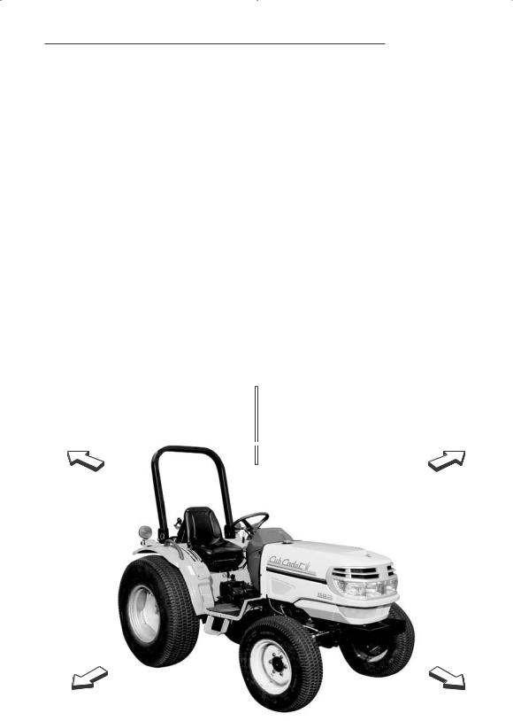
NOTE: Expressions such as LEFT, RIGHT, FRONT, or REAR used in this manual should be understood in accordance with following rules: FRONT means the front grill end while REAR means the lifting arm end of the tractor. LEFT or RIGHT means the left or right hand side of the tractor looking forward from operator’s seat.
TURN RIGHT  TURN LEFT
REAR |
LEFT |
RIGHT |
FRONT |
I
SERIAL NUMBERS
SERIAL NUMBERS
Write your machine Model Name and Serial Numbers of major components on the lines provided. If needed, give these numbers to your dealer when you need parts or information for your machine.
1.TRACTOR MODEL NAME
2.TRACTOR SERIAL NUMBER
3.ENGINE SERIAL NUMBER
4.ROPS SERIAL NUMBER
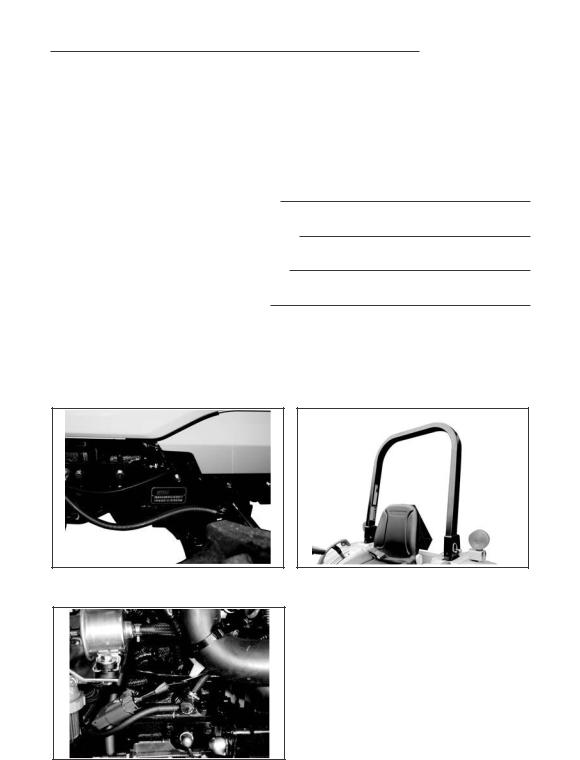
SERIAL NUMBER LOCATIONS
TRACTOR MODEL NUMBER AND ROPS SERIAL NUMBER PLATE SERIAL NUMBER PLATE
ENGINE SERIAL NUMBER
II

GENERAL TABLE OF CONTENTS
Safety/Decals |
1~13 |
Specifications |
14~18 |
Instruments/Controls |
19~35 |
Operating Instructions |
36~54 |
Field Operation |
55~64 |
Tires/Wheels/Ballast |
65~75 |
Lubrication/Filters/Fluids |
76~103 |
Maintenance/Adjustments |
104~109 |
Electrical System |
110~116 |
Storage |
117~118 |
III

SAFETY/DECALS
SAFETY PRECAUTIONS
REMEMBER: “SAFETY” IS ONLY A WORD UNTIL IT IS PUT INTO PRACTICE
Improper handling of the tractor could cause an accident. Prior to the operation of the tractor, be sure to read this Manual carefully and have a thorough understanding of all of the contents. In particular, the instructions given in this section entitled “Safety Precautions” must be strictly followed.
A. GENERAL OPERATING SAFETY PRECAUTION
1.Observe all the safety precautions in this manual when operating the tractor.
2.Operate the tractor while wearing tight clothing that allows easy movement.
Avoid loose jackets, mufflers, scarves, or loose shirt sleeves to prevent from being caught by moving parts.
3.Always work when you are in good physical condition by
taking sufficient rest to avoid overwork.
4.Do not allow children or adults having no knowledge of the tractor or tractor operation,
to operate the tractor.
5.Never allows riders on the tractor, linkage drawbar or attachment while traveling and operating them.
B. BASIC SAFETY REQUIREMENTS
FOR MAINTENANCE
Always follow these maintenance instructions before operating
the tractor:
1.Immediately repair the head lights and work lamps required to conform to traffic regulations where the tractor is operated.
2.Keep tractor steps clean to avoid accidents due to slippage.
1

SAFETY/DECALS
3.Cover the PTO shaft with a guard when not using.
4.Be sure to engage the brake and lower any attachment or implement before disassembling any part.
5.Never adjust or service the tractor when it is in motion or while the engine is running. Always adjust the brake or clutch properly in accordance with the adjusting procedure in the instruction book.
6.Do not remove the radiator cap while the engine is running. Shut down the engine and wait until it cools sufficiently. For removal, turn the cap to the first stop to relieve pressure.
To replace the coolant, use the coolant recovery tank.
7.Hydraulic oil or fuel escaping under pressure can penetrate the skin, causing serious injury. Before disconnecting oil or fuel
lines, be sure to relieve all pressure. Before restoring pressure after repair, be sure all connections are tight and all hydraulic components are in normal condition. If injured by leaked fluid, see a doctor immediately for proper treatment.
8.When refueling, be particularly careful first to stop the engine completely to prevent the fuel from igniting. Never refuel in the presence of an open flame or
2
SAFETY/DECALS
9.Before starting any work on electrical equipment or work that may cause you to touch the electrical parts accidentally, first disconnect the battery cables. Never remove the rubber cap cover at the positive terminal of the battery cable end. Before connecting the battery to the charger, make sure that the charger switch is in “OFF” position. Be sure to connect the charger to the correct terminals on the battery (positive to positive, negative to negative).
A great amount of hydrogen gas is generated by the battery when it is being charged. Take precautions against fire: Do not have any exposed flame in the area where you are working.
Be sure not to cause any leakage of the electrolyte, since it will corrode the skin or clothing.
In case of accident as described below, immediately seek first aid, and see a doctor immediately for proper treatment.
a)If the diluted sulfuric acid from the battery has gotten into the eyes:
Cleanse the eyes with a lot of clean running water for more than 15 minutes, while opening the eyes widely.
b)If diluted sulfuric acid from the battery has been swallowed: Rinse the mouth with clean water immediately and drink a lot of raw eggs or milk. Lie down quietly.
c)If diluted sulfuric acid has gotten on the skin of clothing: Wash away the diluted sulfuric acid completely with a lot of clean running water and neutralize with soap solution.
Then rinse with water.
d)If the diluted sulfuric acid is spilled: Wash away with a lot of water or neutralize with slacked lime or bicarbonate of soda.
10. Stop the engine and make sure the PTO shift lever is in Neutral before performing any of the following services, including.
a)Removal of the propeller shaft between PTO and any attachment.
b)Adjustment of PTO drive train and hitch.
c)Adjustment or cleaning of PTO driven attachment.
11.The steering wheel always has built-in play to some extent, which is required for smooth meshing of sector gear and pinion gear. Always inspect the amount of
the play. Do not operate the tractor if there is too much or too little play in the steering.
3
C. OPERATION OF THE Before driving the tractor, follow these rules:
C-1. Before starting and the Tractor
Operate the tractor only seated properly in
and keep a firm grip on steering wheel at all times Never attempt to perform operation of the tractor anywhere else, on or off Always wear a “hard hat” when operating the tractor.
C-2. Starting and Driving the Tractor Always operate the tractor at the proper speeds which enable you to keep the tractor in complete control.
Before leaving the tractor, stop the engine, remove the key, apply the parking brake and make sure that the engine has come to a complete stop, and any attachment is completely touching the ground.
4

SAFETY/DECALS
When starting the engine in an enclosed area or building, ensure proper ventilation by opening the doors and/or windows to prevent carbon monoxide inhalation. Mount the extension exhaust pipe on the tractor which has a cabin.
operating any attachment or engaging the PTO make sure that no one is in the way,
5
C-3. Traveling on Roads and Streets For traveling on roads and streets be sure to lock both brake pedals together before driving to prevent
while driving at high speed or traveling on the road. For driving the 4-WD tractor on the road, be sure to place the 4-WD shift lever in OFF position.
SAFETY/DECALS
C-4. Steering and Turning the Tractor
Slow down your tractor and disengage the differential lock
going into a turn, being prevent any attachments on the front or rear from
anyone or anything
and Operating
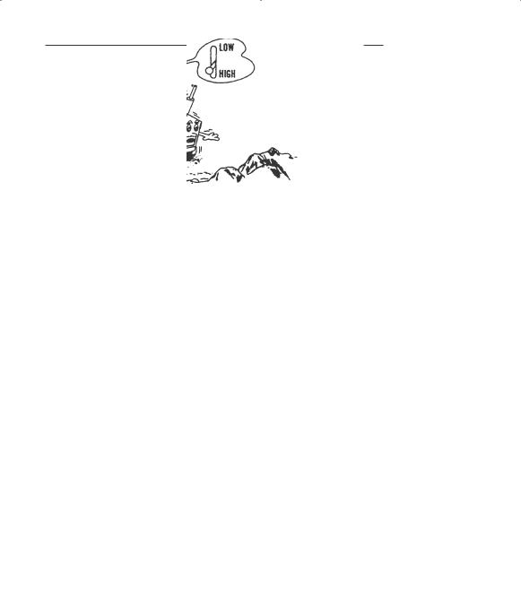
work on downward place the shift lever in low use engine brake.
to reduce the speed with
.
heavy object on a hill is hazardous.
tread of the tractor and mount the wheel weight or chassis weight to increase the stability
6

When operating the tractor on either a steep slope or flat ground, be sure not to suddenly steer, brake, clutch or operate attachments.
Do not operate the tractor at the edge of cliff or slope. Be particularly careful right after the
For towing, be sure to use the drawbar only. Set the hitch point below the center line of the rear axle. When using a chain, never try to
SAFETY/DECALS
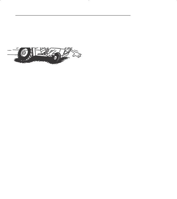
Avoid operating the tractor on an extreme slope that appears hazardous, when forced to operate on such slope, use extra
care. Driving forward out of a ditch or mired condition or up a steep slope could cause tractor to tip over rearward.
Back out of such situation if possible. the situation does not permit you back out, use the front wheel weight or the chassis weight for balancing the tractor lengthwise. Also in case any extra-heavy rear mounting attachment is used, try obtain better balance in this
manner.
. Using Attachment
To mount or operate attachment, follow the instruction manual for the particular attachment for safe operation.
When using agricultural chemicals with an attachment on the tractor, always follow the instructions in the manual for the attachment as well as the instructions provided by the chemical manufacturer.
7
SAFETY/DECALS
DECALS
IMPORTANT: Install new decals if the old decals are destroyed, lost, painted over or can not be read. When parts are replaced that have decals, make sure you install a new decal with each new part.
NOTE: New decals are available from your Dealer.
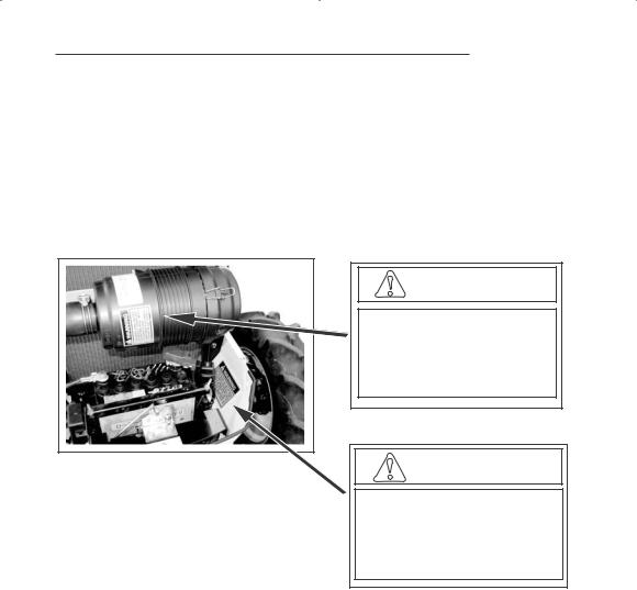
WARNING
EXPLOSION AND INJURY
CAN RESULT FROM USE
OF STARTING AIDS WITH
HOT GLOW PLUGS.
DO NOT INJECT GASOLINE
OR ETHER IN AIR INTAKE.
WARNING
B AT T E R I E S C O N TA I N A C I D A N D E X P L O S I V E
G A S . E X P L O S I O N C A N R E S U LT F R O M
S PA R K S , F L A M E S , O R W R O N G C A B L E C O N -
N E C T I O N S . TO C O N N E C T J U M P E R C A B L E S
O R C H A R G E R , S E E M A N U A L ( S ) F O R T H E
C O R R E C T P R O C E D U R E . FA I L U R E TO
F O L L O W T H E A B O V E I N S T R U C T I O N S C A N
C A U S E S E R I O U S P E R S O N A L I N J U RY O R
D E AT H
32 1 - 6 71 4
8
SAFETY/DECALS
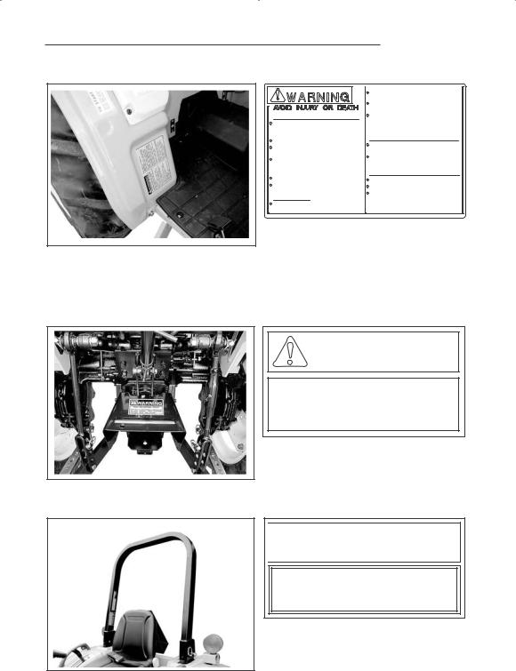
WARNING
ROTATING MACHINE PARTS
STAY CLEAR,KEEP SHIELDS INSTALLED TO HELP PROTECT FROM CLOTHING ENTANGLEMENT AND INJURY.
321-3710

 WARNING
When improperly operated,this tractor can rollover or upset.Use of ROPS and seat belt minimize the possibility of injury or death if rollover or upset occurs.For low clearance use only,the ROPS can be lowered.NO protection is provided in this position and the seat belt should not be fastened.For all other uses.secure ROPS in upright position and fasten seat belt.
1991603C1
9
SAFETY/DECALS
Tractor Roll Over
ROPS is a special safety unit. After an accident the ROPS must be replaced so that you will get the same protection as a new ROPS. ROPS, the seat, the seat belts and all the mounting, accessories and wiring inside the operator’s protective area must be carefully checked after a tractor accident and all parts with damage should be replaced immediately. DO NOT TRY TO MAKE REPAIRS OR WELD ROPS.
Safety Rules
1.Do not make modification to the ROPS. Example, welding an accessory to the ROPS, or drilling a hole in the ROPS.
2.Special fasteners are used to install the operator protective parts. Replacement parts must be the same as given in the Parts Catalog for your tractor.
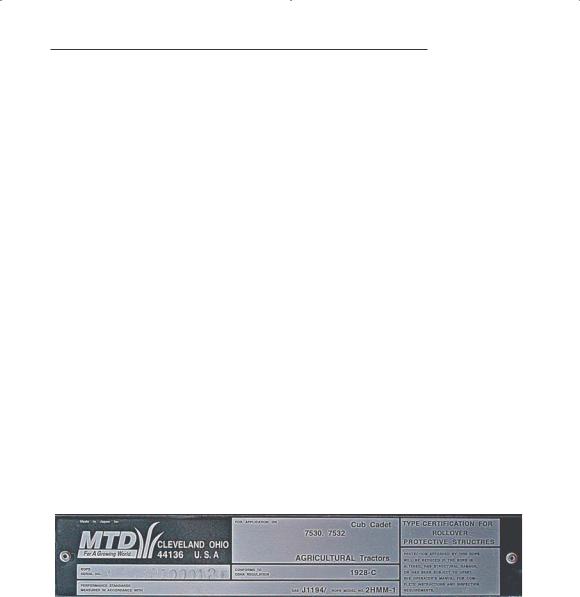
ROPS Label
1.ROPS is equipped with a ROPS label.
2.The label contains the ROPS serial number and applicable standards.
10
SAFETY/DECALS
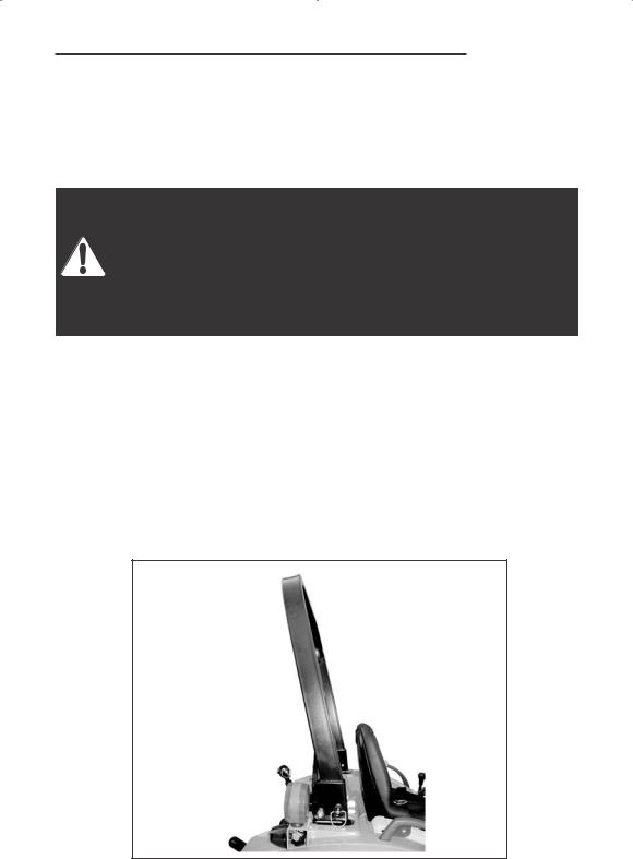
ROLL OVER PROTECTIVE STRUCTURE (ROPS)
Foldable ROPS Frame
When improperly operated, this tractor can roll over or upset. Use of the ROPS and seat belt minimize the possibility of injury or death if rollover or upset occurs. For low clearance use only, the ROPS can be lowered. No protection is provided in this position and the seat belt should not be fastened. For all other uses, secure the ROPS in the upright position and the fasten the seat belt.
ROPS is foldable so that the tractor can be operated in places such as orchards where the height is restricted. See Folding the ROPS in this manual.
Normal Operating Position
For normal operation, including transport, always use the foldable ROPS in the secured upright position with a fastened seat belt for full rollover protection.
11

SAFETY/DECALS
Low Clearance Positions
For low clearance operation, such as operating in buildings, orchards or vineyards, the ROPS can be lowered and secured in the down position. No rollover protection is provided in the lowered positions and the seat belt should not be fastened. When the low clearance operation is completed, return the ROPS to the secured upright position for all other tractor uses and transport.
IMPORTANT: When the ROPS frame is in the lowered position, make sure there is clearance between the frame and hitch mounted equipment. Slowly raise the hitch to maximum height to check for necessary clearance. For drawbar attached and/or PTO driven equipment, check for clearance including turning corners.
12

SAFETY/DECALS
STEP 1 |
STEP 4 |
|
|
ROPS BAR |
HOLE |
( |
NORMAL |
|
POSITIONOPERATING( |
|
|
POSITION
PIN
SLIT
SLIT
While holding the ROPS bar. CAREFULLY pull the position pins.
STEP 2
POSITION PIN
And then Rotate position pin to (90 ).
STEP 3
ROPS BAR
CAREFULLY move the ROPS bar to the desired position.
Rotate position pin and insert GUIDE to SLIT. In this state, move ROPS bar up and down and position pin is installed completely ROPS bar can set at three position.
STEP 5
ROPS BAR
UPRIGHT |
( |
(POSITION |
|
POSITION PIN
Adjustment of Foldable ROPS.
If you feel less friction when the ROPS is in the upright position, tighten the nut untill you feel the right friction in the movement.
Rollover protection is provided only with proper assembly. Lock pins, must be in place. Correct parts may be obtained from your dealer.
13

|
|
SPECIFICATIONS |
|
|
|
DIESEL ENGINE |
||
General |
|
|
Type |
Three Cylinders, Four Stroke Cycle, |
|
|
Valve in Cylinder Head, Cross |
|
|
Flow Porting |
|
Firing Order |
1-3-2 |
|
Bore |
84mm (3.307 inch) |
|
Stroke |
90mm (3.543 inch) |
|
Piston Displacement |
1496cm3(91.29 Cubic inch) |
|
Compression Radio |
|
18.0 to 1 |
Governor Engine Speed without Load |
2670 to 2730 RPM |
|
Rated Engine Speed |
|
2500 RPM |
Engine Idle Speed |
1005 to 1055 RPM |
|
Maximum Horsepower (Per SAE J816b & J245) |
||
7530 |
30 HP at 2500 RPM |
|
7532 |
32 HP at 2500 RPM |
|
Valve Clearance (Intake and Exhaust Cold Engine) |
||
|
0.25 mm (0.010 inch) |
|
IMPORTANT: Valve clearance adjustment must be made when the engine is not running and is cold.
Engine Lubrication System
Oil Pressure |
296 to 441kPa (43 to 64 PSI) at 2500 |
|
Engine RPM with 20 W Oil at |
Fuel System |
93.3 C (200 F) |
|
|
Fuel Injection Pump |
BOSCH M Plunger In Line |
|
NIPPONDENSO ND – PFR |
Injection Pump Timing |
|
|
11Degrees Before Top Dead Center (BTDC) |
Fuel Injectors |
Hole Type, NIPPONDENSO, ND – DLLA150P |
14

Air Intake System
Type
Cooling System
Type
Radiator
Thermostat
Pressure Cap
Water Temperature
SPECIFICATIONS
Dry Type Air Cleaning System with 2nd Filter
Pressure System, Thermostat
Controlled Bypass, Impeller Type Pump
Corrugated and Wave Fin Type
Start to Open at Approx.82 C (180 F) Fully Open at 95 C (203 F)
88.3kPa (12.8PSI) Thermometer on Instrument Panel
Tractor Brakes
Type
Operation
Parking Brakes
Transmission
Type
Gear Drive
Hydrostatic Drive
Gear Selection
Gear Drive
Hydrostatic Drive
Shift Control
Gear Drive
Hydrostatic Drive
Oil Cooler
POWER TRAIN
Wet Disk Plate Type
Mechanical
Hand Operating Lock Type
Synchromesh on shuttle shift (forward-reverse section) and main Gear Shift of constant mesh with two Ranges of Selective Sliding Gears
Hydrostatic Transmission with Three
Ranges of Selective Sliding Gears
8 Speeds Forward and 8 Speeds Reverse
3 Speed ranges in Forward and Reverse with Variable Speeds.
Actuated by Two Shift Levers on the LH Fender and shuttle lever on the column. Actuated by Pedal on the RH Step and lever on the LH Fender
Hydrostatic Drive only
15

SPECIFICATIONS
Clutch
Type, Diameter
Gear Drive |
Dry, Single Disc, Diaphragm Type, |
|
|
||
Hydrostatic Drive |
215mm (8.46 Inch) |
|
Dry, Single Disc, Diaphragm Type, |
||
|
||
|
215mm (8.46 Inch) |
|
Operation |
Mechanical |
Mechanical Front Drive (MFD)
Front Axle |
Spiral Bevel Gear Type Differential |
|
with Bevel Gear Reductions |
Differential Lock
Type |
|
Gear Drive |
Controlled by Pedal on the RH Step |
|
and Mechanically Actuated |
Hydrostatic Drive |
Controlled by Pedal on the LH Step |
|
and Mechanically Actuated |
Steering
Type of Steering Hydrostatic Type
Hitch System
Type |
Three Point, Category |
Type Control |
Position Control |
Type Valve |
Three Positions, Lift, Hold and lower |
Lifting Capacity at 24”behind Lift Point (Per ASAE S349.1) |
|
|
780kg (1720lbs) |
Type of Cylinder |
Single Acting Type |
16

SPECIFICATIONS
Hydraulic System
Hydraulic Pump Type |
Front Mounted, Engine Driven, |
|
Pressure Loading Gear Type |
Capacity |
|
Pump for Three Point Hitch |
27.2 l/min (7.2GPM) |
|
at 2500 Engine RPM |
Pump for Power Steering |
12.3 l/min (3.3GPM) |
|
at 2500 Engine RPM |
Maximum System Pressure |
15200kPa (2204PSI) |
Auxiliary Connector |
Front Hydraulic Block |
Connector Size |
9.5mm (3/8 inch) |
Rear Power Takeoff (PTO)
PTO Type |
|
Gear Drive |
Independent PTO |
Hydrostatic Drive |
Live PTO |
Location |
At the rear of transmission |
Rotation |
Clockwise from rear of tractor |
Shaft Size |
34.9 mm (1.375 Inch) Diameter, 6Splines |
Speed |
540 RPM at 2376 Engine RPM |
Mid Power Takeoff (PTO) OPTION
PTO Type |
|
Gear Drive |
Independent PTO |
Hydrostatic Drive |
Live PTO |
Location |
At the Bottom of Transmission |
Rotation |
Clockwise from Rear of Tractor |
Shaft Size |
25.4mm (1 Inch) Diameter, 15Splines |
Speed |
2000 RPM at 2632 Engine RPM |
Drawbar
Type |
Fixed Type |
Distance from Hitch Hole to the End of PTO Shaft |
358mm (14.092 inch) |
|
|
Maximum Vertical Load on Drawbar |
440Kgf (969Lb) |
17

SPECIFICATIONS
Overall length (To end of Lower link) |
3080 mm (121 inch) |
|
Overall width (To end of tire) |
|
|
7530 |
1360 mm (53.5 inch) |
|
7532 |
1365 mm |
(54 inch) |
Height (To top of ROPS) |
|
|
7530 |
2110 mm |
(83 inch) |
7532 |
2140 mm (84.3 inch) |
|
Wheel base |
|
|
7530 |
1710 mm (67 inch) |
|
Ground Clearance |
|
|
7530 |
370 mm |
(15 inch) |
7532 |
325 mm (12.8 inch) |
|
Turning Radius (with Brake Assistance) |
|
|
7530 |
2300 mm (78.8 inch) |
|
7532 |
2300 mm (78.7 inch) |
|
Weight |
|
|
7530 |
1060 kg (2370 lbs) |
|
7532 |
1115 kg (2456 lbs) |
|
18
INSTRUMENTS/CONTROLS
INSTRUMENTS AND INDICATORS
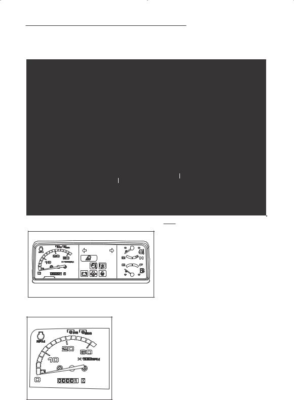
1. TACHOMETER AND HOURMETER |
The tachometer shows the |
|
engine speed in revolutions per |
|
minute (RPM). A symbol on the |
|
face indicates the correct Power |
|
Takeoff (PTO) operating speed. |
|
The hour meter shows the hours |
|
and tenths of hours that the engine |
|
has operated at an average RPM. |
[A] |
[B] |
|
Yellow line [A] shows the 540 rpm of the Rear PTO speed.
Yellow line [B] shows the 2000 rpm of the MID PTO speed.
19
INSTRUMENTS/CONTROLS
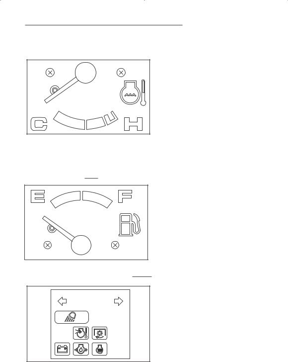
2. ENGINE COOLANT TEMPERATURE GAUGE
The gauge indicates the coolant temperature when the starter key switch is in ON position.
If the engine overheats, the pointer moves right into H position area. In this case, run the engine at 1500 RPM without load until the pointer moves left out from H position area. If the pointer still stays in the H position area, stop the engine immediately and check for the cause.
3. FUEL GAUGE |
The meter shows how much fuel is in the tank. |
NOTE: The pointer can be in any position when the starter key switch is in the OFF position.
4. TURN SIGNAL INDICATORS
The LH indicator on the TACHOMETER will operate when the turn signal switch is turned to the left. The RH indicator will operate when the switch is turned to the right. Both indicators will operate ON and OFF when Hazard switch is pushed down.
20
INSTRUMENTS/CONTROLS
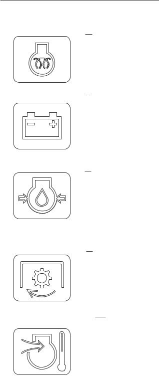
5. ENGINE GLOW PLUG INDICATOR
This signal indicates the correct functioning of the glow plug circuit. When the glow plugs have reached the correct temperature for engine starting, the glow plug indicator lamp will be put out.
6. CHARGE INDICATOR The charge indicator indicates the battery is being discharged. If the lamp illuminates during operation, stop the engine and check for the cause.
7. ENGINE OIL PRESSURE INDICATOR
The engine oil pressure indicator indicates low engine oil pressure. If the engine oil pressure drops below its normal pressure, the engine oil pressure indicator will come on. Shut off the engine immediately. Check for the cause.
8. INDEPENDENT PTO CLUTCH INDICATOR(GEAR DRIVE ONLY)
This signal indicates the INDEPENDENT
PTO CLUTCH is ON or OFF.
9. AIR HEATER INDICATOR This signal indicates AIR HEATER is ON.
21
INSTRUMENTS/CONTROLS
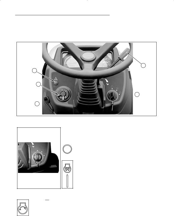
OPERATING CONTROLS
Control Switches
2
4
3
 1
1
5
1. STARTER KEY SWITCH
The starter key switch can be removed with the switch in the OFF position. Four position switch as follows:
|
position |
|
|
Engine and all lamps except |
|
||||
|
(OFF) |
the turn signal and flasher lamps |
||
|
|
are turned off. |
||
|
|
|||
|
Position |
|
|
First position clockwise from |
|
|
|||
|
(HEAT) |
OFF. In this position (Engine not |
||
&running) energizes the glow plugs.
(ON) The charge indicator, glow plug indicator and oil pressure indicator will illuminate.
The fuel gauge and temperature gauge will show correct values.
position |
Turn the key fully clockwise against the force of the |
(START) |
spring in the switch. The starter motor will turn the engine. |
|
Release the key immediately when engine starts. |
NOTE: To prevent operation by persons not authorized and the possible discharge of the battery, remove the starter key when you leave the tractor.
IMPORTANT: Do not keep the starter key switch in the ON position for a long period of time when the engine is not operating.
22
 Loading...