


Chamberlain 1156, 1145jg, 1160jg, 1140, 1160 User Manual
...INSTRUCTIONS
with 433MHz Radio Controls
QLD Office: |
17 Oasis Court |
|
|
Clontarf 4019 |
|
|
(07) |
3883-0200 |
NSW Office: |
34-36 Marigold Street |
|
|
Revesby 2212 |
|
|
(02) |
9722 5555 |
VIC/TAS Office: |
147-153 Canterbury Road |
|
|
Kilsyth 3137 |
|
|
(03) |
9237 7766 |
B&D Doors |
|
|
New Zealand: |
70 Allens Road |
|
|
EastTamaki |
|
|
Auckland, New Zealand |
|
|
(09) |
273 8600 |
|
www.bnd.co.nz |
|
SA Office: |
23 Frederick Road |
|
Royal Park 5014 |
|
(08) 8447 4747 |
WA Office: |
96 Mulgul Road |
|
Malaga 6090 |
|
(08) 9247 8777 |
The Controll-A-Door-P has been tested and complies with the standards:
AS/NZS 3350.2.95:2000 (incl. Amdt1) & AS/NZS CISPR 14.1:2003

TABLE OF CONTENTS |
|
|
Introduction |
|
2-7 |
Safety rule review........................................................ |
|
2 |
Preparing your garage door ........................................ |
|
3 |
Tools needed............................................................... |
|
3 |
Planning .................................................................. |
|
4-5 |
Carton inventory .......................................................... |
|
6 |
Hardware inventory ..................................................... |
|
7 |
Assembly |
|
8-10 |
Assemble the rail & attach the chain pulley bracket ...8 |
||
Install the trolley .......................................................... |
|
9 |
Fasten rail to motor unit .............................................. |
|
9 |
Install chain & attach chain spreader..................... |
|
9-10 |
Install the chain noise reduction pads....................... |
|
10 |
Installation |
11-24 |
|
Installation safety instructions.................................... |
|
11 |
Determine the header bracket location................ |
|
12-13 |
Install the header bracket.......................................... |
|
14 |
Attach the rail to the header bracket......................... |
|
15 |
Position the opener .............................................. |
|
15-16 |
Hang the opener .................................................. |
|
16-17 |
Install the door control............................................... |
|
17 |
Install the remote control wall mount (optional) ........ |
17 |
|
Wiring instructions for optional accessories.............. |
|
18 |
Install the light globe ................................................. |
|
19 |
Attach the emergency release rope and handle |
.......19 |
|
Connect electric power.............................................. |
|
19 |
Installing the safety infra-red safety sensors............. |
|
20 |
Fasten the door bracket....................................... |
|
21-22 |
Connect door arm to trolley ................................. |
|
23-24 |
INTRODUCTION |
|
|
Safety Rule Review |
|
|
Adjustment Section |
25-27 |
Adjust the travel limits ............................................... |
25 |
Adjust the force ......................................................... |
26 |
Test the safety reverse system ................................. |
27 |
Testing the safety infra-red safety sensors ............... |
27 |
Operation |
28-30 |
Operation safety instructions..................................... |
28 |
Using your garage door opener ................................ |
28 |
To open the door manually........................................ |
29 |
Care of your opener .................................................. |
29 |
Troubleshooting......................................................... |
30 |
Programming |
31 |
To code a hand-held remote control ......................... |
31 |
To erase all codes ..................................................... |
31 |
Multi-function remotes ............................................... |
31 |
Warranty |
32 |
This garage door opener is designed and tested to offer safe service provided it is installed, operated, maintained and tested in strict accordance with the warnings, safety instructions and instructions contained in this manual.
 WARNING
Mechanical
 WARNING
Electrical
CAUTION
When you see these Safety Symbols and Signal Words on the following pages, they will alert you to the possibility of serious injury or death if you do not comply with the corresponding instructions. The hazard may come from something mechanical or from electric shock. Read the instructions carefully.
When you see this Signal Word on the following pages it will alert you to the possibility of damage to your garage door and/or the garage door opener if you do not comply with the corresponding instructions. Read them carefully.
114A2845 |
2 |
Preparing your garage door
•Disable locks. Insert wood screws or nails to keep them unlocked.
•Remove any ropes connected to garage door.
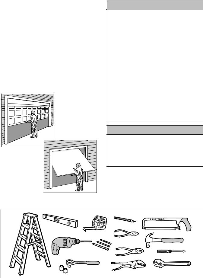
TESTING YOUR DOOR
Before you begin, complete the following test to make sure your door is balanced and is not sticking or binding:
•Lift the door about halfway as shown. Release the door. It should stay in place, supported entirely by its springs.
•Raise and lower the door to see if there is any binding or sticking.
If your door binds, sticks, or is out of balance, call for professional garage door service.
Sectional Door |
One-Piece Door
 WARNING
To prevent possible SERIOUS INJURY OR DEATH:
•Always call for professional B&D garage door service if garage door binds, sticks, or is out of balance. An unbalanced garage door might not reverse when required.
•NEVER try to loosen, move, or adjust garage door, door springs, cables, pulleys, brackets or their hardware, all of which are under EXTREME tension.
•Disable ALL locks and remove all ropes connected to garage door before installing and operating garage door opener to avoid entanglement.
•This unit should not be installed in a damp or wet space.
•The door must not extend over public byway during operation.
•This product is provided with a power supply cord of special design which, if damaged, must be replaced by a power supply cord of the same type; such a power supply cord may be obtained from you local B&D distributor and must be fitted by a specialist.
•This unit is supplied as a plug-in-device and it is strongly advised that this unit remain a plug-in device. Any alterations or changes to this will result in the opener warranty being void.
CAUTION
To avoid damage to the garage door and opener, disable locks before installing and operating the opener. Use a wood screw or nail to hold locks in the "open" (unlocked) position.
Operation at other than 230V/50 Hz will cause opener malfunction and damage.
Tools needed
During assembly, installation and adjustment of the opener, instructions will call for hand tools as illustrated.
Carpenter's
Level
Drill
Stepladder
Pencil
1 |
2 |
|
|
Tape Measure |
|
Hack Saw |
|
|
|
||
|
|
Wire Cutters |
|
|
|
|
Claw Hammer |
8mm, 5mm, and |
|
|
|
4mm Drill Bits |
Pliers |
Screwdriver |
|
13mm, 11mm, and 6mm |
Locking pliers |
Adjustable End Wrench |
|
Sockets and Wrench |
|||
114A2845 |
3 |
Planning |
|
|
|
• |
Do you have an access door in addition to the |
|||||
Identify the type and height of your garage door. |
|
|
garage door? If not, Model T7012 Emergency |
|||||||
|
|
Access Device is required. |
|
|||||||
Survey your garage area to see if any of the |
|
|
|
|||||||
|
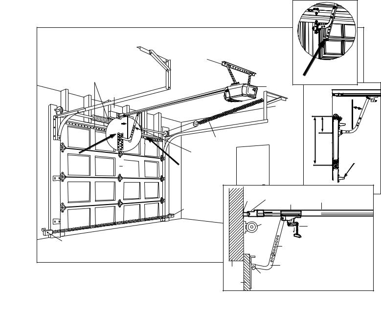
SECTIONAL DOOR INSTALLATIONS |
|||||||||
conditions below apply to your installation. Additional |
||||||||||
materials may be required. You may find it helpful to |
• |
Do you have a steel, aluminum, fibreglass or glass |
||||||||
refer back to this page and the accompanying |
|
|
panel door? If so, horizontal and vertical reinforce- |
|||||||
illustrations as you proceed with the installation of |
|
ment is required (Installation Step 11). |
||||||||
your opener. |
|
|
|
• |
The opener is normally installed at the centre of |
|||||
Depending on your requirements, there are several |
||||||||||
|
the door. If there is a torsion spring or centre |
|||||||||
installation steps which may call for materials and/or |
|
bearing plate in the way of the header bracket or |
||||||||
hardware not included in the carton. |
|
|
door bracket area, the opener may be installed |
|||||||
• Installation Step 1 – Look at the wall or ceiling |
|
|
within 300mm to the left or right of the door centre. |
|||||||
above the garage door. The header bracket must |
|
See Installation Steps 1 and 11. |
||||||||
be securely fastened to structural supports. |
|
• |
Look at the garage door where it meets the floor. It |
|||||||
• Installation Step 5 – Do you have a finished ceiling |
|
must close on the floor all the way across. |
||||||||
in your garage? If so, a support bracket and |
|
|
Otherwise, the safety reverse system may not work |
|||||||
additional fastening hardware may be required. |
|
|
properly. See Adjustment Step 3. Floor or door |
|||||||
B&D recommends the use of safety infrared |
|
|
should be repaired. |
|
|
|||||
reversing sensors on all installations of |
|
OPENER ARM MOUNTING LOCATION |
||||||||
automatic garage door openers. |
|
Must be mounted on a stile. Add an additional stile if |
||||||||
• Installation Step 10: |
|
|
|
|||||||
|
|
|
required or offset mount the opener (see below and |
|||||||
– Depending upon garage construction, extension |
page 5). Attach arm 1/3 panel height from top at 10O |
|||||||||
brackets or wood blocks may be needed to |
|
as shown. |
|
|
|
|
||||
install the infrared safety sensors. |
|
|
|
|
|
|
|
|||
– Alternate floor mounting of the infrared safety |
|
|
|
|
|
|
|
|||
sensors will require hardware not provided. |
|
|
|
|
|
|
|
|||
Sectional Door Installation |
FINISHED CEILING |
|
|
|
|
|||||
|
|
|
|
|
|
|
||||
Horizontal and vertical reinforcement |
Support bracket & |
|
|
|
|
|||||
fastening hardware |
|
|
|
|
||||||
is needed for lightweight garage doors |
is required. |
|
|
|
|
|
|
|||
(fibreglass, steel, aluminum, door with |
See page 17. |
|
|
|
|
|
||||
glass panels, etc.). |
|
|
|
|
|
|
|
|
Excess MUST |
|
See page 21 for details. |
|
|
|
|
|
|
|
|||
|
|
|
|
|
|
|
be removed |
|||
|
|
|
|
|
|
|
|
|
||
|
|
|
|
|
|
|
Motor Unit |
|
||
|
Header Wall |
|
|
|
|
|
|
|
||
|
|
|
|
|
|
|
|
|
10o |
|
|
|
10o |
|
|
|
|
|
|
1/3 |
|
|
|
|
|
|
Extension Spring |
|
|
Height |
||
|
|
|
|
|
|
|
Panel |
|||
|
|
|
|
OR |
|
|
|
|||
|
|
|
|
|
|
|
|
|||
Centre Stile |
|
|
Torsion Spring |
Access |
|
|
|
|||
— |
|
|
|
|
Door |
|
|
Re-enforcement |
||
optimum |
|
|
|
|
|
|
||||
|
|
|
|
|
|
|
||||
— |
Door |
|
|
|
|
|
|
|
||
location for |
Must be attached below |
|
|
|
|
|||||
attachment |
— |
Centre |
Panel Re-enforcement |
|
|
|
|
|||
|
|
|
if used. |
|
|
|
|
|
|
|
|
— |
|
|
|
|
|
|
|
CLOSED POSITION |
|
|
— |
|
|
|
|
Header |
Header |
|
||
|
|
|
|
|
|
|
||||
|
— |
|
|
|
|
|
|
|||
|
|
|
|
|
Bracket |
Sleeve Bracket |
Rail Assembly |
|||
|
|
|
Safety |
|
|
|
|
Trolley |
||
|
|
|
|
|
|
|
|
|||
|
— |
|
Reversing |
|
|
|
|
|
|
|
|
|
Sensor |
|
|
|
|
|
|
||
|
— |
|
|
|
|
|
|
|
||
|
|
|
|
|
|
Garage |
|
Emergency |
||
|
|
|
|
|
|
|
|
|||
|
|
|
|
|
|
|
Door |
|
Release |
|
|
Gap between floor and bottom of |
|
|
|
|
Spring |
|
Rope & Handle |
||
|
|
|
|
|
|
|
|
|||
|
door must not exceed 6mm. |
|
|
|
|
|
Straight |
|
||
|
|
|
|
|
|
|
|
|
||
Safety Reversing Sensor |
|
|
|
|
|
|
Door |
|
||
|
|
|
|
|
|
|
|
Arm |
|
|
|
|
|
|
|
|
|
|
Curved |
|
|
|
|
|
|
|
Header |
|
Door |
|
||
|
|
|
|
|
|
Arm |
|
|||
|
|
|
|
|
Wall |
Door |
|
|
||
|
|
|
|
|
Garage |
|
|
|||
|
|
|
|
|
Bracket |
|
|
|||
114A2845 |
|
|
4 |
|
Door |
|
|
|
|
|
|
|
|
|
|
|
|
|
|||
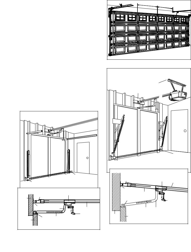
OFF CENTRE INSTALLATION OF OPENER |
1/4 |
Door |
|
|
|
|
|
||
In situations where obstruction prevent mounting the |
|
Width |
1/4 |
Door Width |
|
|
|
|
|
opener centrally, offsetting the opener attachment is |
|
|
|
|
possible within the following range - 1/4 Door width |
|
|
|
|
from centre. |
|
|
|
|
NOTE: Even though it is acceptable practise to off |
|
|
|
|
centre mount the opener, the further off centre the |
|
|
|
|
opener is mounted the more dependent is the door |
|
|
|
|
operation on a good installation. This relates to |
|
|
|
|
correct set-up of opener and track, and correct door |
|
|
|
|
balance. |
|
|
|
|
The installation of the IR Safety Sensor is |
|
|
|
|
recommended for an off centre mount application. |
|
|
|
|
ONE-PIECE DOOR INSTALLATIONS |
|
|
|
|
•Generally, a one-piece door does not require reinforcement. If your door is lightweight, you can refer to the information relating to sectional doors
|
in Installation Step 11. |
One-Piece Door without Track |
• |
Depending on your door’s construction, you may |
FINISHED CEILING |
|
need additional mounting hardware for the door |
|
|
Support bracket & fastening |
|
|
bracket (Step 11). |
|
|
hardware is required. See page 17. |
|
• |
The gap between the bottom of the garage door |
Header |
|
and the floor cannot exceed 6mm. Otherwise, the |
Wall |
|
|
|
|
safety reverse system may not work properly. See |
|
|
Adjustment Step 3. The floor or the door should be |
|
|
repaired. |
|
|
One-Piece Door with Track |
Access Door |
|
|
|
|
|
|
|
|
Safety |
|
|
|
|
|
|
Gap between floor and bottom |
Reversing |
|
|
|
|
|
|
|
Sensor |
||
|
|
|
|
|
|
of door must not exceed 6mm. |
||
|
|
|
|
Safety Reversing Sensor |
|
|||
|
|
|
|
|
|
|
||
|
|
|
Safety |
|
CLOSED POSITION |
|
||
|
|
|
|
Header |
|
|
|
|
|
|
Gap between floor |
Reversing Sensor |
|
|
|
|
|
|
|
and bottom of door |
|
|
Sleeve Bracket |
|
Trolley |
Chain |
|
Safety |
must not exceed 6mm. |
|
|
|
|
||
|
|
|
|
|
|
|||
|
Reversing Sensor |
|
|
|
|
|
|
|
|
CLOSED POSITION |
|
|
Header |
|
|
|
|
|
|
Trolley |
|
|
Bracket |
Rail |
|
|
|
|
|
|
|
|
|
||
Header |
Header Sleeve Bracket |
|
|
|
|
Emergency |
||
|
|
|
|
Door Bracket |
|
|||
Wall |
|
|
|
|
|
Release |
||
|
|
|
|
|
|
|||
|
|
|
|
|
|
|
Rope & |
|
|
Header |
Curved |
Rail |
|
|
|
Handle |
|
|
Bracket |
Door Arm |
|
|
Straight |
Curved |
|
|
|
|
|
Emergency |
|
|
|
||
|
|
|
|
|
Door |
Door |
|
|
|
|
|
Release |
|
|
|
||
|
|
|
Header |
Garage |
Arm |
Arm |
|
|
|
Door |
Straight |
Rope & Handle |
|
||||
|
|
|
|
|||||
Garage |
|
Wall |
Door |
|
|
|
||
Bracket Door |
|
|
|
|
||||
|
|
|
|
|
|
|||
Door |
|
Arm |
|
|
|
|
|
|
114A2845 |
|
|
|
5 |
|
|
|
|
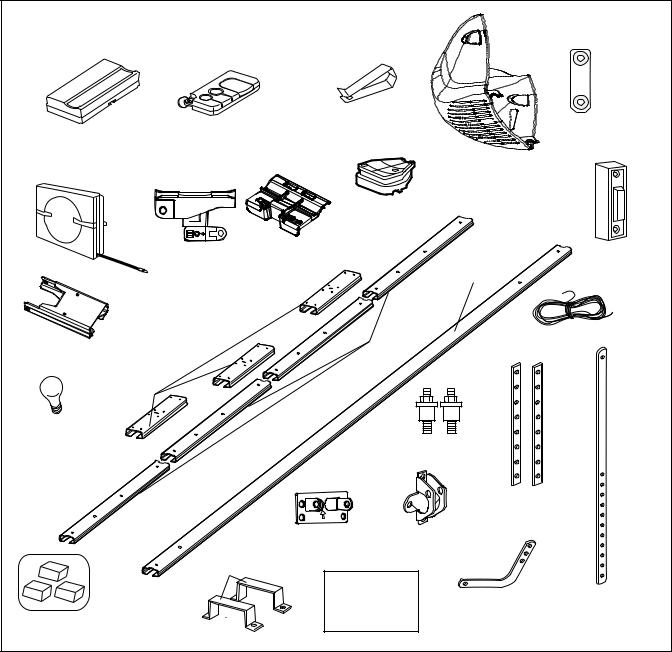
Carton Inventory
Your garage door opener is packaged in two cartons which contains the motor unit and the parts illustrated below. If anything is missing, carefully check the packing material. Parts may be stuck in the foam.
Hardware for assembly and installation is shown on the next page. Save the carton and packing material until installation and adjustment is complete.
|
Remote Control |
|
Remote Control |
|
Transmitter Visor Clip |
||
1-Function Remote |
3-Function Mini Remote |
|
Wall Mount Bracket |
Control Transmitter (1) |
Control Transmitter (1) |
|
|
|
|
Light Lens (1) |
|
|
Chain Spreader with Screws |
Illuminated |
|
|
Push Button |
||
|
and Washers |
||
|
|
||
|
Inner Trolley |
|
|
|
Trolley |
|
|
Chain |
|
1-Piece Rail |
|
|
|
|
|
|
4-Piece Rail |
Bell Wire |
|
Header Sleeve Bracket |
|
||
|
|
|
|
Rail |
|
|
|
Centre |
|
|
|
Light globe |
|
|
|
|
|
Vibration Isolators |
|
|
|
Hanging Brackets |
|
|
Header Bracket |
Door Bracket |
|
|
Rail Straps |
|
|
|
Safety Labels |
|
|
|
and |
Curved Door |
Straight Door |
Chain Noise |
Literature |
Arm Section |
Arm Section |
|
|
|
|
Reduction Pads |
|
|
|
114A2845 |
6 |
|
|
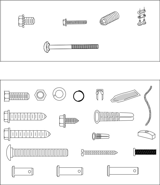
Hardware Inventory
Separate all hardware and group as shown below for the assembly and installation procedures.
ASSEMBL
Washered Screw 25mm (4) |
Screw (2) |
Spri /Trolley Nut (1) |
Master |
|
(mo |
in opener) |
|
|
Link (2) |
Carriage bolt (1)
|
|
|
INSTALLATION |
|
|
|
Hex Screw |
Nut |
Lock Washer |
Insulated |
Rail Grease |
Rope |
|
8mm x 20mm (4) |
8mm (7) |
8mm (7) |
Ring Fastener (4) |
Staples |
|
|
|
|
|
||||
Lag Screw |
|
|
|
Anchors |
|
|
8mm x 40mm (4) |
|
|
|
|
|
|
|
|
|
8mm x 40mm (6) |
|
||
|
|
|
|
|
||
|
|
Sheet Metal Screw |
|
|
|
|
|
|
8mm x 13mm (2) |
|
NOT |
||
|
|
|
|
|
||
|
|
|
|
|
|
ICE |
Lag Screw |
|
|
|
Dry Wall Anchors (2) |
Handle |
|
8mm x 45mm (2) |
|
|
|
|
|
|
|
|
|
|
|
|
|
|
|
|
|
Screw |
Sto |
olt (1) |
Carriage Bolt |
|
|
6AB x 25mm (2) |
|
|
|
8mm x 65mm (2) |
|
|
|
|
|
|
Clevis Pin |
|
|
Clevis Pin |
|
Clevis Pin |
|
8mm x 13mm (2) |
|
|
8mm x 25mm (2) |
|
8mm x 32mm (1) |
|
114A2845 |
|
|
7 |
|
|
|

ASSEMBLY STEP 1
Assemble the Rail
NOTE: If your opener came with a one piece rail, proceed to Assembly step 2, page 9.
Grease inside edges of rail brace sections. Place rail pieces on flat surface for assembly. All four rail sections are interchangeable. Slide rail braces onto rail section. Connect rail by sliding rail brace onto next rail section. Tap rail assembly on piece of wood until rail sections are flush. Repeat with remaining rail sections.
Install the Chain
Remove chain from carton and lay chain out on floor (do not allow chain to twist). Push pins of master link bar through chain link and hole in back end of trolley. Push cap over pins and onto notches. Slide clip-on spring over cap and onto pin notches until both pins are securely locked in place.
Insert Chain into Rail & Assemble Header Sleeve
Slide pulley bracket and inner trolley into back (opener end) of rail assembly, be sure to insert pulley bracket as shown with arrow pointing toward front (header end) of rail. Push bracket toward front (header end) of rail. Insert carriage bolt through header sleeve bracket. Loosely thread spring nut onto carriage bolt. Insert carriage bolt of header sleeve assembly into bold cut out in pulley bracket. Slide header sleeve assembly on to front (header end) of rail.
INSTALLING THE CHAIN
Back End of Trolley
 Spring
Cap
Chain Link
 Master Link Bar
Front (Header End)
of Rail
|
Carriage Bolt |
|
Header Sleeve |
|
Bracket |
Spring Nut |
|
Header Sleeve |
Carriage Bolt |
Bracket |
|
Pulley
Bracket
114A2845 |
8 |
HARDWARE SHOWN ACTUAL SIZE |
Spring Trolley Nut |
Carriage Bolt |
RAIL ASSEMBLY
Rail Piece
Rail Brace
Rail
 Piece
Piece
Grease
Rail assembly
Piece of Wood
|
w |
Back |
rro |
A |
|
(Opener End) |
|
of Rail |
|
Assembly |
|
Pulley
 Bracket
Inner
Trolley
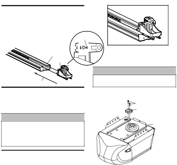
ASSEMBLY STEP 2
Attach Trolley to Rail
Slide outer trolley into rail assembly, be sure arrow
on trolley is heading in direction of door |
|
|
|
|
|
|
|
|
in |
|
|||
direction of door. Slide outer trolley down |
until it |
|
|||||||||||
engages with inner trolley. |
|
|
|
|
|
|
|
|
|
|
|
|
|
|
|
|
|
|
|
|
|
|
|
|
Arrow |
|
|
|
|
|
|
|
|
|
|
|
|
|
|
|
|
|
|
|
|
|
|
|
|
|
|
|
|
|
|
|
|
|
|
|
|
|
|
|
|
|
|
|
|
|
|
|
|
|
|
|
|
|
|
|
|
|
|
Rail Assembly
Outer Trolley
 Arrow
Arrow
Towards Door
CAUTION
To avoid serious damage to opener, ONLY use screws mounted in top of motor unit.
ASSEMBLY STEP 3
Attach Chain Spreader
Attach chain spreader to opener with phillips pan head screws.
 WARNING
To avoid possible SERIOUS INJURY to fingers from moving garage door opener:
•ALWAYS keep hand clear of sprocket while operating opener.
•Securely attach chain spreader before operating.
ASSEMBLY STEP 4
Fasten Rail to Opener & Install Chain
Remove four washered bolts from top of opener. Place rail on opener, flush with stops on top of opener. Wrap chain around slot in spreader and over sprocket. Push idler pulley bracket assembly toward front of the rail to eliminate excess slack in chain. Align bolt holes on brackets with bolt holes on opener. Secure brackets to opener with previously removed bolts . Tighten bolts securely. The opener sprocket teeth must engage the chain. Insert bolt into trolley stop bolt hole secure with lock washer and nut.
CAUTION: Use only those bolts mounted in the top of opener. Use of any other bolts will cause serious damage to opener.
Set Chain Tension
Thread spring nut on carriage bolt unit finger tight. Insert a screwdriver tip into one of the slots of the nut ring and brace it firmly against the header sleeve. Place an open end wrench on the square end of the spring nut, slightly rotate nut about 1/4 turn clockwise until nut ring is released against header sleeve. This sets spring to optimum chain tension. chain may slip off sprocket if chain is too loose. If chain does slip retighten spring nut by turing nut clockwise 1/2 turn.
Do NOT overtighten chain.
Phillips Pan Head Screws
Chain Spreader
Opener
114A2845 |
9 |

SET CHAIN TENSION |
|
|
FASTEN RAIL TO OPENER |
|
|
|||
|
|
|
|
|
|
Spreader |
|
|
|
|
|
|
|
|
Stops |
|
|
|
|
|
HARDWARE SHOWN |
|
|
|
|
|
|
|
|
ACTUAL SIZE |
|
|
|
|
|
|
|
|
Spring /Trolley Nut |
|
|
|
|
|
|
|
|
|
|
|
|
d Bolt |
|
|
|
|
|
|
|
Washere |
|
|
|
|
|
|
|
|
|
|
Stops |
|
|
|
|
|
|
|
|
Spreader |
|
|
|
|
|
|
et |
|
et |
|
|
|
|
|
|
|
Sprock |
|
|
|
|
|
|
Sprock |
|
|
|
|
|
Nut Ring |
|
|
|
|
|
|
|
Wrench |
|
Screwdriver |
Bolt |
|
|
|
|
|
|
Tip |
|
|
|
|
||
|
|
|
|
|
|
|
|
|
|
|
|
|
|
2 |
|
|
|
|
|
|
|
Trolley Stop |
|
|
4 |
|
|
|
|
|
|
|
|
|
|
|
|
|
|
Bolt Hole |
|
|
|
|
|
Spring Nut |
|
|
Lock |
Nut |
|
|
|
|
|
|
|
Washer |
|
|
|
|
|
|
|
|
|
|
|
|
|
|
Header Sleeve |
|
|
|
Lock Washer |
Nut |
||
|
|
|
|
|
Bolt |
|||
|
|
|
|
|
|
|||
|
|
|
|
|
|
|
|
|
Square |
Trolley |
Square |
Trolley |
|
|
|
|
|
|
End |
|
|
|
|
|
|
|
End |
Nut Ring |
|
Nut Ring |
|
|
|
|
|
BEFORE |
AFTER RELEASE |
25mm |
32mm |
ASSEMBLY STEP 5
Install Chain Noise Reduction Pads (optional)
1.Clean and remove grease from rail in areas where pads will be installed.
114mm |
2.With chain tensioned, lift up the chain and place noise reduction pads under the chain in orientation shown.
114A2845 |
10 |
114mm |
3.Install with adhesive side down allowing pad to stick to rail.
 Loading...