


RAMPAGE IV FORMULA
Motherboard

E7112
Revised Edition
January 2012
Copyright © 2012 ASUSTeK COMPUTER INC. All Rights Reserved.
No part of this manual, including the products and software described in it, may be reproduced, transmitted, transcribed, stored in a retrieval system, or translated into any language in any form or by any means, except documentation kept by the purchaser for backup purposes, without the express written permission of ASUSTeK COMPUTER INC. (“ASUS”).
Product warranty or service will not be extended if: (1) the product is repaired, modified or altered, unless such repair, modification of alteration is authorized in writing byASUS; or (2) the serial number of the product is defaced or missing.
ASUS PROVIDES THIS MANUAL “AS IS” WITHOUT WARRANTY OF ANY KIND, EITHER EXPRESS OR IMPLIED, INCLUDING BUT NOT LIMITED TO THE IMPLIED WARRANTIES OR CONDITIONS OF MERCHANTABILITY OR FITNESS FOR A PARTICULAR PURPOSE. IN NO EVENT SHALL ASUS, ITS DIRECTORS, OFFICERS, EMPLOYEES OR AGENTS BE LIABLE FOR ANY INDIRECT, SPECIAL, INCIDENTAL, OR CONSEQUENTIAL DAMAGES (INCLUDING DAMAGES FOR LOSS OF PROFITS, LOSS OF BUSINESS, LOSS OF USE OR DATA, INTERRUPTION OF BUSINESS AND THE LIKE), EVEN IF ASUS HAS BEEN ADVISED OF THE POSSIBILITY OF SUCH DAMAGES ARISING FROM ANY DEFECT OR ERROR IN THIS MANUAL OR PRODUCT.
SPECIFICATIONS AND INFORMATION CONTAINED IN THIS MANUAL ARE FURNISHED FOR INFORMATIONAL USE ONLY, AND ARE SUBJECT TO CHANGE AT ANY TIME WITHOUT NOTICE, AND SHOULD NOT BE CONSTRUED AS A COMMITMENT BY ASUS. ASUS ASSUMES NO RESPONSIBILITY OR LIABILITY FOR ANY ERRORS OR INACCURACIES THAT MAY APPEAR IN THIS MANUAL, INCLUDING THE PRODUCTS AND SOFTWARE DESCRIBED IN IT.
Products and corporate names appearing in this manual may or may not be registered trademarks or copyrights of their respective companies, and are used only for identification or explanation and to the owners’ benefit, without intent to infringe.
Offer to Provide Source Code of Certain Software
This product may contain copyrighted software that is licensed under the General Public License (“GPL”) and under the Lesser General Public License Version (“LGPL”). The GPL and LGPL licensed code in this product is distributed without any warranty. Copies of these licenses are included in this product.
You may obtain the complete corresponding source code (as defined in the GPL) for the GPL Software, and/or the complete corresponding source code of the LGPL Software (with the complete machinereadable “work that uses the Library”) for a period of three years after our last shipment of the product including the GPL Software and/or LGPL Software, which will be no earlier than December 1, 2011, either
(1) for free by downloading it from http://support.asus.com/download; or
(2) for the cost of reproduction and shipment, which is dependent on the preferred carrier and the location where you want to have it shipped to, by sending a request to:
ASUSTeK Computer Inc.
Legal Compliance Dept.
15 Li Te Rd.,
Beitou, Taipei 112
Taiwan
In your request please provide the name, model number and version, as stated in the About Box of the product for which you wish to obtain the corresponding source code and your contact details so that we can coordinate the terms and cost of shipment with you.
The source code will be distributed WITHOUT ANY WARRANTY and licensed under the same license as the corresponding binary/object code.
This offer is valid to anyone in receipt of this information.
ASUSTeK is eager to duly provide complete source code as required under various Free Open Source Software licenses. If however you encounter any problems in obtaining the full corresponding source code we would be much obliged if you give us a notification to the email address gpl@asus.com, stating the product and describing the problem (please do NOT send large attachments such as source code archives etc to this email address).
ii

Contents
Notices ........................................................................................................................ |
vi |
Safety information....................................................................................................... |
x |
About this guide......................................................................................................... |
xii |
RAMPAGE IV FORMULA specifications summary................................................. |
xiv |
Chapter 1: |
Product introduction |
|
|
1.1 |
Welcome! |
..................................................................................................... |
1-1 |
1.2 |
Package contents....................................................................................... |
1-1 |
|
1.3 |
Special features.......................................................................................... |
1-2 |
|
|
1.3.1 ........................................................................ |
Product highlights |
1-2 |
|
1.3.2 ............................................................. |
ROG Exclusive Features |
1-3 |
|
1.3.3 ........................................................................ |
Sound with Clarity |
1-5 |
|
1.3.4 ......................................................... |
Future Transfer Technology |
1-5 |
|
1.3.5 ........................................................................ |
Software Bundled |
1-6 |
Chapter 2: |
Hardware information |
|
|
2.1 |
Before you proceed.................................................................................... |
2-1 |
|
2.2 |
Motherboard overview............................................................................... |
2-2 |
|
|
2.2.1 |
Motherboard layout...................................................................... |
2-2 |
|
2.2.2 |
Central Processing Unit (CPU).................................................... |
2-4 |
|
2.2.3 |
System memory........................................................................... |
2-5 |
|
2.2.4 |
Expansion slots.......................................................................... |
2-12 |
|
2.2.5 |
Onboard switches...................................................................... |
2-14 |
|
2.2.6 |
Onboard LEDs........................................................................... |
2-18 |
|
2.2.7 |
Jumper....................................................................................... |
2-26 |
|
2.2.8 |
Internal connectors.................................................................... |
2-27 |
2.3 |
Building your computer system.............................................................. |
2-38 |
|
|
2.3.1 |
Additional tools and components to build a PC system............. |
2-38 |
|
2.3.2 |
CPU installation......................................................................... |
2-39 |
|
2.3.3 |
CPU heatsink and fan assembly installation.............................. |
2-41 |
|
2.3.4 |
DIMM installation....................................................................... |
2-43 |
|
2.3.5 |
Motherboard installation............................................................ |
2-44 |
|
2.3.6 |
ATX Power connection.............................................................. |
2-46 |
|
2.3.7 |
SATA device connection............................................................ |
2-47 |
|
2.3.8 |
Front I/O Connector................................................................... |
2-48 |
|
2.3.9 |
Expansion Card installation....................................................... |
2-49 |
|
2.3.10 |
Rear panel connection............................................................... |
2-50 |
|
2.3.11 |
Audio I/O connections................................................................ |
2-52 |
2.4 |
Starting up for the first time.................................................................... |
2-54 |
|
iii

Contents
2.5 Turning off the computer.........................................................................2-54
Chapter 3: |
BIOS setup |
|
|
3.1 |
Knowing BIOS............................................................................................. |
3-1 |
|
3.2 |
BIOS setup program................................................................................... |
3-1 |
|
|
3.2.1 |
Advanced Mode........................................................................... |
3-2 |
|
3.2.2 |
EZ Mode...................................................................................... |
3-4 |
3.3 |
Extreme Tweaker menu.............................................................................. |
3-5 |
|
3.4 |
Main menu................................................................................................. |
3-18 |
|
|
3.4.1 |
System Language [English]....................................................... |
3-18 |
|
3.4.2 |
System Date [Day xx/xx/xxxx]................................................... |
3-18 |
|
3.4.3 |
System Time [xx:xx:xx].............................................................. |
3-18 |
|
3.4.4 |
Security...................................................................................... |
3-19 |
3.5 |
Advanced menu........................................................................................ |
3-21 |
|
|
3.5.1 |
CPU Configuration..................................................................... |
3-22 |
|
3.5.2 |
SystemAgent Configuration...................................................... |
3-24 |
|
3.5.3 |
PCH Configuration..................................................................... |
3-24 |
|
3.5.4 |
SATAConfiguration.................................................................... |
3-25 |
|
3.5.5 |
USB Configuration..................................................................... |
3-26 |
|
3.5.6 |
Onboard Devices Configuraton................................................. |
3-27 |
|
3.5.7 |
APM........................................................................................... |
3-29 |
3.6 |
Monitor menu............................................................................................ |
3-30 |
|
3.7 |
Boot menu................................................................................................. |
3-34 |
|
3.8 |
Tools menu................................................................................................ |
3-36 |
|
|
3.8.1 |
ASUS EZ Flash 2 Utility............................................................. |
3-36 |
|
3.8.2 |
ASUS SPD Information.............................................................. |
3-37 |
|
3.8.3 |
ASUS O.C. Profile..................................................................... |
3-38 |
|
3.8.4 |
BIOS FlashBack........................................................................ |
3-39 |
|
3.8.5 |
GO Button File........................................................................... |
3-40 |
3.9 |
Exit menu................................................................................................... |
3-41 |
|
3.10 |
Updating BIOS.......................................................................................... |
3-42 |
|
|
3.10.1 |
ASUS Update utility................................................................... |
3-42 |
|
3.10.2 |
ASUS EZ Flash 2 Utility............................................................. |
3-46 |
|
3.10.3 |
ASUS CrashFree BIOS 3 utility................................................. |
3-47 |
|
3.10.4 |
ASUS BIOS Updater.................................................................. |
3-48 |
|
3.10.5 |
USB BIOS Flashback................................................................ |
3-51 |
Chapter 4: |
Software support |
|
|
4.1 |
Installing an operating system.................................................................. |
4-1 |
|
4.2 |
Support DVD information........................................................................... |
4-1 |
|
iv
Contents
|
4.2.1 |
Running the support DVD............................................................ |
4-1 |
|
4.2.2 |
Obtaining the software manuals.................................................. |
4-2 |
4.3 |
Software information.................................................................................. |
4-3 |
|
|
4.3.1 |
AI Suite II..................................................................................... |
4-3 |
|
4.3.2 |
TurboV EVO................................................................................ |
4-4 |
|
4.3.3 |
DIGI+ Power Control................................................................... |
4-8 |
|
4.3.4 |
EPU........................................................................................... |
4-10 |
|
4.3.5 |
FAN Xpert.................................................................................. |
4-11 |
|
4.3.6 |
Sensor Recorder........................................................................ |
4-12 |
|
4.3.7 |
Probe II...................................................................................... |
4-13 |
|
4.3.8 |
USB 3.0 Boost........................................................................... |
4-14 |
|
4.3.9 |
Ai Charger+............................................................................... |
4-15 |
|
4.3.10 |
ASUS Update............................................................................ |
4-16 |
|
4.3.11 |
MyLogo2.................................................................................... |
4-17 |
|
4.3.12 |
ROG Connect............................................................................ |
4-19 |
|
4.3.13 |
Audio configurations.................................................................. |
4-22 |
|
4.3.14 |
Sound Blaster X-Fi MB 2 .......................................................... |
4-23 |
4.4 |
RAID configurations................................................................................. |
4-26 |
|
|
4.4.1 |
RAID definitions......................................................................... |
4-26 |
|
4.4.2 |
Installing Serial ATA hard disks.................................................. |
4-27 |
|
4.4.3 |
Setting the RAID item in BIOS................................................... |
4-27 |
|
4.4.4 |
Intel® Rapid Storage Technology Option ROM utility................. |
4-27 |
4.5 |
Creating a RAID driver disk..................................................................... |
4-31 |
|
|
4.5.1 |
Creating a RAID driver disk without entering the OS................. |
4-31 |
|
4.5.2 |
Creating a RAID driver disk in Windows®.................................. |
4-31 |
|
4.5.3 |
Installing the RAID driver during Windows® OS installation....... |
4-32 |
|
4.5.4 |
Using a USB floppy disk drive................................................... |
4-33 |
Chapter 5: |
Multiple GPU technology support |
|
|
5.1 |
AMD® CrossFireX™ technology................................................................ |
5-1 |
|
|
5.1.1 |
Requirements.............................................................................. |
5-1 |
|
5.1.2 |
Before you begin.......................................................................... |
5-1 |
|
5.1.3 |
Installing two CrossFireX™ graphics cards................................. |
5-2 |
|
5.1.4 |
Installing the device drivers......................................................... |
5-3 |
|
5.1.5 |
Enabling the AMD® CrossFireX™ technology............................. |
5-3 |
5.2 |
NVIDIA® SLI™ technology.......................................................................... |
5-4 |
|
|
5.2.1 |
Requirements.............................................................................. |
5-4 |
|
5.2.2 |
Installing two SLI-ready graphics cards....................................... |
5-4 |
|
5.2.3 |
Installing the device drivers......................................................... |
5-5 |
|
5.2.4 |
Enabling the NVIDIA® SLI™ technology...................................... |
5-5 |
|
|
|
|
Notices
Federal Communications Commission Statement
This device complies with Part 15 of the FCC Rules. Operation is subject to the following two conditions:
•This device may not cause harmful interference, and
•This device must accept any interference received including interference that may cause undesired operation.
This equipment has been tested and found to comply with the limits for a Class B digital device, pursuant to Part 15 of the FCC Rules. These limits are designed to provide reasonable protection against harmful interference in a residential installation. This equipment generates, uses and can radiate radio frequency energy and, if not installed and used in accordance with manufacturer’s instructions, may cause harmful interference to radio communications. However, there is no guarantee that interference will not occur in a particular installation. If this equipment does cause harmful interference to radio or
television reception, which can be determined by turning the equipment off and on, the user is encouraged to try to correct the interference by one or more of the following measures:
•Reorient or relocate the receiving antenna.
•Increase the separation between the equipment and receiver.
•Connect the equipment to an outlet on a circuit different from that to which the receiver is connected.
•Consult the dealer or an experienced radio/TV technician for help.
The use of shielded cables for connection of the monitor to the graphics card is required to assure compliance with FCC regulations. Changes or modifications to this unit not expressly approved by the party responsible for compliance could void the user’s authority to operate this equipment.
FCC Radio Frequency (RF) Exposure Caution Statement
Any changes or modifications not expressly approved by the party responsible for compliance could void the user’s authority to operate this equipment. “The manufacture declares that this device is limited to Channels 1 through 11 in the 2.4GHz frequency by specified firmware controlled in the USA.”
This equipment complies with FCC radiation exposure limits set forth for an uncontrolled environment. To maintain compliance with FCC RF exposure compliance requirements, please avoid direct contact to the transmitting antenna during transmitting. End users must follow the specific operating instructions for satisfying RF exposure compliance.
RF exposure warning
This equipment must be installed and operated in accordance with provided instructions and the antenna(s) used for this transmitter must be installed to provide a separation distance of at least 20 cm from all persons and must not be co-located or operating in conjunction with any other antenna or transmitter. End-users and installers must be provide with antenna installation instructions and transmitter operating conditions for satisfying RF exposure compliance.
vi
Declaration of Conformity (R&TTE directive 1999/5/EC)
The following items were completed and are considered relevant and sufficient:
•Essential requirements as in [Article 3]
•Protection requirements for health and safety as in [Article 3.1a]
•Testing for electric safety according to [EN 60950]
•Protection requirements for electromagnetic compatibility in [Article 3.1b]
•Testing for electromagnetic compatibility in [EN 301 489-1] & [EN 301 489-17]
•Effective use of the radio spectrum as in [Article 3.2]
•Radio test suites according to [EN 300 328-2]
CE Mark Warning
CE marking for devices without wireless LAN/Bluetooth
The shipped version of this device complies with the requirements of the EEC directives 2004/108/EC “Electromagnetic compatibility” and 2006/95/EC “Low voltage directive”.
CE marking for devices with wireless LAN/ Bluetooth
This equipment complies with the requirements of Directive 1999/5/EC of the European Parliament and Commission from 9 March, 1999 governing Radio and Telecommunications Equipment and mutual recognition of conformity.
vii

Wireless Operation Channel for Different Domains
N.America |
2.412-2.462 |
GHz |
Ch01 through CH11 |
Japan |
2.412-2.484 GHz |
Ch01 through Ch14 |
|
Europe ETSI 2.412-2.472 |
GHz |
Ch01 through Ch13 |
|
France Restricted Wireless Frequency Bands
Some areas of France have a restricted frequency band. The worst case maximum authorized power indoors are:
•10mW for the entire 2.4 GHz band (2400 MHz–2483.5 MHz)
•100mW for frequencies between 2446.5 MHz and 2483.5 MHz
Channels 10 through 13 inclusive operate in the band 2446.6 MHz to 2483.5 MHz.
There are few possibilities for outdoor use: On private property or on the private property of public persons, use is subject to a preliminary authorization procedure by the Ministry of Defense, with maximum authorized power of 100mW in the 2446.5–2483.5 MHz band. Use outdoors on public property is not permitted.
In the departments listed below, for the entire 2.4 GHz band:
•Maximum authorized power indoors is 100mW
•Maximum authorized power outdoors is 10mW
Departments in which the use of the 2400–2483.5 MHz band is permitted with an EIRP of |
|||||||
less than 100mW indoors and less than 10mW outdoors: |
|
|
|||||
01 |
Ain |
02 |
Aisne |
03 |
Allier |
05 |
Hautes Alpes |
08 |
Ardennes |
09 |
Ariège |
11 Aude |
12 |
Aveyron |
|
16 |
Charente |
24 |
Dordogne |
25 |
Doubs 26 Drôme |
41 |
Loir et Cher |
32 |
Gers |
36 |
Indre |
37 |
Indre et Loire |
||
45 |
Loiret |
50 |
Manche |
55 |
Meuse 58 Nièvre |
63 |
Puy du Dôme |
59 |
Nord |
60 |
Oise |
61 |
Orne |
||
64 |
Pyrénées Atlantique |
66 |
Pyrénées Orientales |
Saône et Loire |
|||
67 |
Bas Rhin |
68 |
Haut Rhin |
70 |
Haute Saône |
71 |
|
75 |
Paris |
82 |
Tarn et Garonne |
84 |
Vaucluse |
|
|
88 |
Vosges |
89 |
Yonne |
90 |
Territoire de Belfort |
|
|
94 |
Val de Marne |
|
|
|
|
|
|
This requirement is likely to change over time, allowing you to use your wireless LAN card in more areas within France. Please check with ART for the latest information (www.arcep.fr)
Your WLAN Card transmits less than 100mW, but more than 10mW.
viii
Canadian Department of Communications Statement
This digital apparatus does not exceed the Class B limits for radio noise emissions from digital apparatus set out in the Radio Interference Regulations of the Canadian Department of Communications.
This class B digital apparatus complies with Canadian ICES-003.
Cet appareil numérique de la classe [B] est conforme à la norme NMB-003 du Canada.
IC Radiation Exposure Statement for Canada
This equipment complies with IC radiation exposure limits set forth for an uncontrolled environment. To maintain compliance with IC RF exposure compliance requirements, please avoid direct contact to the transmitting antenna during transmitting. End users must follow the specific operating instructions for satisfying RF exposure compliance.
Operation is subject to the following two conditions:
•This device may not cause interference and
•This device must accept any interference, including interference that may cause undesired operation of the device.
To prevent radio interference to the licensed service (i.e. co-channel Mobile Satellite systems) this device is intended to be operated indoors and away from windows to provide maximum shielding. Equipment (or its transmit antenna) that is installed outdoors is subject to licensing.
The user is cautioned that this device should be used only as specified within this manual to meet RF exposure requirements. Use of this device in a manner inconsistent with this manual could lead to excessive RF exposure conditions.
This device and its antenna(s) must not be co-located or operating in conjunction with any other antenna or transmitter.
Country Code selection feature to be disabled for products marketed to the US/CANADA.
ix
Safety information
Electrical safety
•To prevent electrical shock hazard, disconnect the power cable from the electrical outlet before relocating the system.
•When adding or removing devices to or from the system, ensure that the power cables for the devices are unplugged before the signal cables are connected. If possible, disconnect all power cables from the existing system before you add a device.
•Before connecting or removing signal cables from the motherboard, ensure that all power cables are unplugged.
•Seek professional assistance before using an adapter or extension cord. These devices could interrupt the grounding circuit.
•Ensure that your power supply is set to the correct voltage in your area. If you are not sure about the voltage of the electrical outlet you are using, contact your local power company.
•If the power supply is broken, do not try to fix it by yourself. Contact a qualified service technician or your retailer.
•The optical S/PDIF is an optional component (may or may not be included in your motherboard) and is defined as a CLASS 1 LASER PRODUCT.
INVISIBLE LASER RADIATION, AVOID EXPOSURE TO BEAM.
•Never dispose of the battery in fire. It could explode and release harmful substances into the environment.
•Never dispose of the battery with your regular household waste. Take it to a hazardous material collection point.
•Never replace the battery with an incorrect battery type.
•RISK OF EXPLOSION IF BATTERY IS REPLACED BY AN INCORRECT TYPE.
•DISPOSE OF USED BATTERIES ACCORDING TO THE ABOVE BATTERYRELATED INSTRUCTIONS.
Operation safety
•Before installing the motherboard and adding devices on it, carefully read all the manuals that came with the package.
•Before using the product, ensure all cables are correctly connected and the power cables are not damaged. If you detect any damage, contact your dealer immediately.
•To avoid short circuits, keep paper clips, screws, and staples away from connectors, slots, sockets and circuitry.
•Avoid dust, humidity, and temperature extremes. Do not place the product in any area where it may become wet.
This motherboard should only be used in environments with ambient temperatures between 5ºC (41ºF) and 40ºC (104ºF).
•Place the product on a stable surface.
•If you encounter technical problems with the product, contact a qualified service technician or your retailer.
REACH
Complying with the REACH (Registration, Evaluation, Authorisation, and Restriction of Chemicals) regulatory framework, we published the chemical substances in our products at ASUS REACH website at http://csr.asus.com/english/REACH.htm.
DO NOT throw the motherboard in municipal waste. This product has been designed to enable proper reuse of parts and recycling. This symbol of the crossed out wheeled bin indicates that the product (electrical and electronic equipment) should not be placed in municipal waste. Check local regulations for disposal of electronic products.
DO NOT throw the mercury-containing button cell battery in municipal waste. This symbol of the crossed out wheeled bin indicates that the battery should not be placed in municipal waste.
xi

About this guide
This user guide contains the information you need when installing and configuring the motherboard.
How this guide is organized
This guide contains the following parts:
•Chapter 1: Product introduction
This chapter describes the features of the motherboard and the new technology it supports.
•Chapter 2: Hardware information
This chapter lists the hardware setup procedures that you have to perform when installing system components. It includes description of the switches, jumpers, and connectors on the motherboard.
•Chapter 3: BIOS setup
This chapter tells how to change system settings through the BIOS Setup menus. Detailed descriptions of the BIOS parameters are also provided.
•Chapter 4: Software support
This chapter describes the contents of the support DVD that comes with the motherboard package and the software.
•Chapter 5: Multiple GPU technology support
This chapter describes how to install and configure multipleAMD CrossFireX™ and
NVIDIA® SLI™ graphics cards.
Where to find more information
Refer to the following sources for additional information and for product and software updates.
1.ASUS websites
The ASUS website provides updated information on ASUS hardware and software products. Refer to the ASUS contact information.
2.Optional documentation
Your product package may include optional documentation, such as warranty flyers, that may have been added by your dealer. These documents are not part of the standard package.
xii

Conventions used in this guide
To ensure that you perform certain tasks properly, take note of the following symbols used throughout this manual.
DANGER/WARNING: Information to prevent injury to yourself when trying to complete a task.
CAUTION: Information to prevent damage to the components when trying to complete a task.
IMPORTANT: Instructions that you MUST follow to complete a task.
NOTE: Tips and additional information to help you complete a task.
Typography
Bold text |
Indicates a menu or an item to select. |
Italics |
Used to emphasize a word or a phrase. |
<Key> |
Keys enclosed in the less-than and greater-than sign means |
|
that you must press the enclosed key. |
|
Example: <Enter> means that you must press the Enter or |
|
Return key. |
<Key1+Key2+Key3> |
If you must press two or more keys simultaneously, the key |
|
names are linked with a plus sign (+). |
|
Example: <Ctrl+Alt+Del> |
Command |
Means that you must type the command exactly as shown, |
|
then supply the required item or value enclosed in brackets. |
|
Example: At the DOS prompt, type the command line: |
|
afudos /iR4F.ROM |
xiii

RAMPAGE IV FORMULA specifications summary
CPU
Chipset
Memory
Expansion Slots
Multi-GPU Technology
Storage
LAN
Audio
2nd Generation Intel® Core™ i7 processor family for the LGA 2011 Socket
Supports Intel® Turbo Boost Technology 2.0
* Refer to www.asus.com for Intel CPU support list
Intel® X79 Express Chipset
4 x DIMM, max. 32GB, DDR3 2400(O.C.)/ 2200(O.C.)/2133(O.
C.)/2000(O.C)/1800(O.C.)/1600/1333/1066MHz,non-ECC,un- buffered memory modules
Quad channel memory architecture
Supports Intel® Extreme Memory Profile (XMP)
* Hyper DIMM support is subject to the physical characteristics of individual CPUs. Some hyper DIMMs only support one DIMM per channel. Please refer to www.asus.com or this user manual for the Memory QVL (Qualified Vendors List) for details.
4 x PCIe3.0 x16 (red) slots, support x16; x16/x16; x16/x8/x16 and x16/x8/x8/x8 configurations
2 x PCIe2.0 x1 slot
* This motherboard is ready to support PCIe 3.0 SPEC. Functions will be available when using PCIe 3.0-compliant devices. Please refer to www.asus.com for updated details.
Supports NVIDIA® 4-Way SLI™ / AMD 4-Way CrossFireX™ Technology
* The 4-Way SLI™ bridge is sold separately.
Intel® X79 Express Chipset built-in:
- 2 x SATA 6Gb/s ports (red) - 4 x SATA 3Gb/s ports (black) - Support Raid 0, 1, 5, 10
ASMedia® ASM1061 controller:
- 2 x SATA 6Gb/s port(s) (red) - 2 x eSATA 6Gb/s port(s)
Intel® Gigabit LAN Controller
SupremeFX III, built-in 8-Channel High Definition Audio
CODEC
- Output Signal-to-Noise Ratio (A-Weighted): 110 dB
- Output THD+N at 1kHz: 95 dB
- Supports: Jack-detection, Multi-streaming, Front Panel Jackretasking
Audio Feature:
SupremeFX Shielding™ Technology 1500 uF Audio Power Capacitor Golden-plated jacks
- X-Fi® Xtreme Fidelity™
- EAX® Advanced™ HD 5.0
- THX® TruStudio PRO™
- Creative® ALchemy
- Blu-ray audio layer Content Protection - Optical S/PDIF out port(s) at back panel
(continued on the next page)
xiv

RAMPAGE IV FORMULA specifications summary
USB |
ASMedia® USB 3.0 controller: |
|
|
- 6 x USB 3.0 port(s) (4 at back panel, 2 at mid-board ) |
|
|
Intel® X79 Chipset: |
|
|
- 12 x USB 2.0 port(s) (6 ports at back panel, 1 for ROG |
|
|
Connect; 6 ports at mid-board) |
|
ROG Exclusive Features |
ROG Extreme OC kit |
|
|
- |
Slow Mode |
|
- |
LN2 Mode |
|
- PCIe x16 Lane switch |
|
|
- |
Q_Reset |
|
- |
EZ Plug |
|
ROG Connect: |
|
|
- |
RC Diagram |
|
- |
RC Remote |
|
- |
RC Poster |
|
- |
GPU TweakIt |
|
ROG Extreme Engine Digi+ II |
|
|
- 8 phase CPU power |
|
|
- 3 phase VCCSA power |
|
|
- 2+2 phase DRAM power |
|
|
UEFI BIOS features : |
|
|
- |
ROG BIOS Print |
|
- |
GPU.DIMM Post |
|
CPU Level Up |
|
|
ROG GameFirst |
|
|
ProbeIt |
|
|
iROG |
|
|
Extreme Tweaker |
|
|
USB BIOS Flashback |
|
|
Loadline Calibration |
|
|
Intelligent overclocking tools |
|
|
- ASUS AI Booster Utility |
|
|
- |
O.C. Profile |
|
Overclocking Protection |
|
|
- COP EX (Component Overheat Protection - EX) |
|
|
- |
Voltiminder LED II |
|
- ASUS C.P.R.(CPU Parameter Recall) |
|
|
|
(continued on the next page) |
xv

RAMPAGE IV FORMULA specifications summary
Special Features |
ASUS EPU Engine |
|
|
|
ASUS Exclusive Features |
|
|
|
- |
MemOK! |
|
|
- Onboard Switches: Power/Reset/Clr CMOS (at rear) |
|
|
|
ASUS Quiet Thermal Solution |
|
|
|
- |
ASUS Fan Xpert |
|
|
ASUS EZ DIY |
|
|
|
- |
ASUS O.C. Profile |
|
|
- ASUS CrashFree BIOS 3 |
|
|
|
- ASUS EZ Flash 2 |
|
|
|
- |
ASUS MyLogo 2 |
|
|
ASUS Q-Design |
|
|
|
- |
ASUS Q-Connector |
|
|
- ASUS Q-LED (CPU, DRAM, VGA, Boot Device LED) |
|
|
|
- |
ASUS Q-Slot |
|
|
- |
ASUS Q-DIMM |
|
Back I/O Ports |
1 x PS/2 keyboard/mouse Combo port(s) |
|
|
|
1 x Clear CMOS button(s) |
|
|
|
1 x Optical S/PDIF out |
|
|
|
1 x ROG Connect On/Off switch |
|
|
|
6 x USB 2.0 port(s) (1 can be switched to ROG Connect) |
|
|
|
4 x USB 3.0 port(s) (blue) |
|
|
|
2 x eSATA 6Gb/s |
|
|
|
1 x LAN (RJ45) port(s) |
|
|
|
6 x Audio jack(s) |
|
|
Internal I/O Connectors |
1 x USB 3.0 connector(s) support(s) additional 2 USB 3.0 port(s) |
|
|
|
3 x USB 2.0 connector(s) support(s) additional 6 USB 2.0 port(s) |
|
|
|
4 x SATA 6Gb/s connector(s) |
|
|
|
4 x SATA 3Gb/s connector(s) |
|
|
|
2 x CPU Fan connector(s) |
|
|
|
3 x Chassis Fan connector(s) |
|
|
|
3 x Optional Fan connector(s) |
|
|
1 x 24-pin EATX Power connector(s)
1 x 8-pin EATX 12V Power connector(s)
8 x ProbeIt Measurement Points
3 x Thermal sensor connector(s)
1 x EZ Plug connector(s) (4-pin Molex power connector) 1 x Power-on button(s)
1 x Reset button(s)
1 x Go Button(s)
1 x LN2 mode jumper
1 x Slow Mode switch
1 x S/PDIF out header(s)
1 x Front panel audio connector(s) (AAFP)
1 x System panel connector
(continued on the next page)
xvi

RAMPAGE IV FORMULA specifications summary
BIOS
Manageability
Software
Form Factor
2 x 64Mb UEFI BIOSs, PnP, DMI2.0, WfM2.0, SM BIOS 2.5, ACPI2.0a Multi-Language BIOS
WfM2.0, DMI2.0, WOL by PME, WOR by PME, PXE
Drivers
Sound Blaster® X-Fi MB2 Utility
Kaspersky® Anti-Virus
DAEMON Tools Pro Standard
ROG CPU-Z
Mem TweakIt
ASUS WebStorage
ASUS Utilities
ATX Form Factor
12 inch x 9.6 inch (30.5cm x 24.4cm)
*Specifications are subject to change without notice.
xvii

xviii

Chapter 1
Chapter 1: |
Product introduction |
1.1Welcome!
Thank you for buying an ROG RAMPAGE IV FORMULA motherboard!
The motherboard delivers a host of new features and latest technologies, making it another standout in the long line of ASUS quality motherboards!
Before you start installing the motherboard, and hardware devices on it, check the items in your package with the list below.
1.2Package contents
Check your motherboard package for the following items.
Motherboard |
ROG RAMPAGE IV FORMULA |
Accessories |
1 x ROG Connect cable |
|
1 x 3-Way SLI bridge |
|
1 x SLI bridge |
|
1 x CrossFire cable |
|
1 x 2-in-1 ASUS Q-Connector Kit |
|
2 x 2-in-1 SATA 3Gb/s signal cables |
|
2 x 2-in-1 SATA 6Gb/s signal cables |
|
1 x I/O Shield |
|
1 x ROG theme label |
|
1 x 12-in-1 ROG Cable label |
|
1 x X-Socket pad module |
Application DVD |
ROG motherboard support DVD |
Documentation |
User guide |
|
ROG exclusive feature guide |
Chapter 1
If any of the above items is damaged or missing, contact your retailer.
ROG RAMPAGE IV FORMULA |
1-1 |

1 Chapter
1.3Special features
1.3.1Product highlights
Republic of Gamers
The Republic of Gamers consists only the best of the best. We offer the best hardware engineering, the fastest performance, the most innovating ideas, and we welcome the best gamers to join in. In the Republic of Gamers, mercy rules are only for the weak, and bragging rights means everything. We believe in making statements and we excel in competitions.
If your character matches our trait, then join the elite club, make your presence felt, in the Republic of Gamers.
LGA2011 Intel® Sandy Bridge-E Processor
This motherboard supports the latest Intel® Sandy Bridge-E processors in the LGA2011 package, with memory and PCI Express controllers integrated to support 4-channel (4 DIMM) DDR3 memory and x16 PCI Express 3.0 lanes. This provides great graphics performance.
Intel® Sandy Bridge-E processors are among the most powerful and energy efficient CPUs in the world.
Intel® X79 Express Chipset
The Intel® X79 Express Chipset is the latest single-chipset design that supports the new
socket 2011 Intel® Core™ i7 Extreme Edition processors. It improves performance by utilizing serial point-to-point links, allowing for increased bandwidth and stability. Additionally, the
X79 comes with 2 SATA 6Gb/s and 4 SATA 3Gb/s ports for faster data retrieval, doubling the bandwidth of current bus systems.
PCIe 3.0 Ready
The latest PCI Express bus standard delivers improved encoding for twice the performance of current PCIe 2.0. Total bandwidth for a x16 link reaches a maximum of 32GB/s, double the 16GB/s of PCIe 2.0 (in x16 mode). PCIe 3.0 provides users unprecedented data speeds, combined with the convenience and seamless transition offered by complete backward compatibility with PCIe 1.0 and PCIe 2.0 devices It is a must-have feature PC users aiming to improve and optimize graphics performance, as well as have the latest, most future-proof technology.
* This motherboard is ready to support PCIe 3.0 SPEC. Functions will be available when using PCIe 3.0-compliant devices. Please refer to www.asus.com for updated details.
SLI/CrossFire On-Demand
Why choose when you can have both?
SLI or CrossFireX? Fret no longer because with the ROG RAMPAGE IV FORMULA, you'll be able to run both multi-GPU setups. The board features SLI/CrossFireX on Demand technology, supporting SLI or CrossFireX configuration. Whichever path you take, you can be assured of jaw-dropping graphics at a level previously unseen.
Quad-Channel DDR3 2400(O.C.) support
The motherboard supports DDR3 memory that features data transfer rates of 2400(O.C.)/
2200(O.C.)/ 2133(O.C.)/ 2000(O.C.)/ 1800(O.C.)/ 1600/ 1333/ 1066 MHz to meet the higher bandwidth requirements of the latest 3D graphics, multimedia, and Internet applications. The quad-channel DDR3 architecture enlarges the bandwidth of your system memory to boost system performance.
1-2 |
Chapter 1: Product Introduction |
1.3.2ROG Exclusive Features
Extreme Engine Digi+ II
Optimum power efficiency with premium components and intelligent digital design
The Extreme Engine Digi+ II has been upgraded and equipped with the finest Japan-made
10K Black Metallic capacitors, while the digital VRM design allows you to achieve ultimate performance with adjustable CPU and memory power management frequencies. Precise adjustments create greater efficiency, stability, double lifespan and performance for total system control.
ROG Connect
Plug and Overclock - Tweak it the hardcore way!
Monitor the status of your desktop PC and tweak its parameters in real-time via a notebook— just like a race car engineer—with ROG Connect. ROG Connect links your main system to
a notebook through a USB cable, allowing you to view real-time POST code and hardware status readouts on your notebook, as well as make on-the-fly parameter adjustments at a purely hardware level.
ROG GameFirst
The speed you need to pwn
Low Internet latency allows you to frag more, and get fragged less. That's why ROG has introduced GameFirst, a feature that manages the flow of traffic according to your needs so that you can still listen to online music, download and upload files, and engage in Internet chats without sacrificing the low ping times you need to pwn your opponents.
X-Socket
Pull the ol' switcharoo
Don't junk that expensive LGA1366 heatsink! With X-Socket, switch out the LGA2011 pad for a 1366 one and get more life out of your previous CPU cooler.
ROG BIOS Print
One click, easily share your BIOS settings
ROG offers a whole new EFI BIOS feature to handle the demands of an overclocking experience. RAMPAGE IV FORMULA features ROG BIOS Print which allows users to easily share their BIOS settings to others with the press of a button. The days of using a camera to take BIOS screenshot are over.
GPU.DIMM Post
Easily check the status of your graphics cards and memory in the BIOS!
Notice potential problems even before you enter the OS! Overclockers can save valuable minutes in detecting component failure under extreme conditions. With GPU.DIMM Post, quickly and easily check your graphics cards and memory DIMMs status in the BIOS, potentially keeping that record-breaking overclock!
Chapter 1
ROG RAMPAGE IV FORMULA |
1-3 |

1 Chapter
ProbeIt
Get all hands-on with hardware-based overclocking.
ProbeIt takes the guesswork out of locating the motherboard’s measurement points, identifying them clearly in the form of eight sets of detection points so you’ll know exactly where to get quick yet accurate readings using a multitester.
iROG
Intelligent multiple control at hand
The iROG is a special IC which enables several ROG highlighted functions that gives users full disposal of the motherboard at any stage! This design allows advanced user control and management to be processed purely at a hardware level. iROG greatly increases fun during overclocking for PC enthusiasts and it offers system maintenance and management with more control and efficiency.
BIOS FlashBack
Two BIOS ROM. Two BIOS settings. Twice the overclocking flexibility.
Overclocker’s prayer to have BIOS flexibility is answered! With the new BIOS Flashback, PC enthusiasts can overclock with even more confidence. BIOS Flashback gives overclockers the ability to save two versions of the BIOS simultaneously. Very much like the “SaveGame” function, one BIOS can be used for the overclocking adventure, while the other BIOS is to be stored with any previous version. BIOS Flashback brings the ultimate convenience to overclockers!
USB BIOS FlashBack
Refresh the BIOS can never be that easy
USB BIOS Flashback must be the most convenient way to flash BIOS ever! It allows overclockers to try their BIOS with the simplist way one can imagine. No need to enter the BIOS or the operating system, just plug the thumb drive into the ROG Connect port & push the ROG Connect button for 3 seconds, BIOS would be automatically flashed under standby power. It’s no doubt that USB BIOS Flashback gives overclockers the ultimate convenience!
CPU Level Up
A simple click for instant upgrade!
Ever wish that you could have a more expensive CPU? Upgrade your CPU at no additional cost with ROG’s CPU Level Up! Simply pick the processor you wanted to OC to, and the motherboard will do the rest! See the new CPU speed and enjoy that performance instantly. Overclocking is never as easy as this.
Extreme Tweaker
One stop performance tuning shop
Extreme Tweakers is the one stop shop to fine-tune your system to optimal performance.
No matter if you’re looking for frequency adjustment, over-voltage options, or memory timing settings, they’re all here!
1-4 |
Chapter 1: Product Introduction |

Voltiminder LED II
Friendly reminder on Voltage Settings
In the pursuit of extreme performance, overvoltage adjustment is critical but risky. Acting as the “red zone” of a tachometer, the Voltiminder LED displays the voltage status for CPU, NB,
SB, and Memory in a intuitive color-coded fashion. The Voltiminder LED allows quick voltage monitoring for overclockers.
COP EX
Maximum OC with confidence with burn proof protection to chipsets and GPU!
The COP EX allows overclockers to increase chipset voltages without the worries of overheating. It can also be used to monitor and save an overheating GPU. The COP EX allows more freedom and less constraint for maximum performance achievement.
Loadline Calibration
Optimal power boost for extreme CPU overclocking!
Maintaining ample voltage support for the CPU is critical during overclocking. The Loadline Calibration ensures stable and optimal CPU voltage under heavy loading. It helps overclockers enjoy the motherboard’s ultimate OC capabilities and benchmark scores.
1.3.3Sound with Clarity
SupremeFX III
Supreme Sound
The SupremeFX III™ onboard audio solution is an 8-channel HD audio equipped with a carefully selected 1500uF capacitor which provides clean, ripple-free audio power and
– perfect for enveloping gaming environments. With a metallic EMI cover and special layout design on the PCB, advanced SupremeFX Shielding™ technology isolates analog audio signals from digital sources for exceptional clarity and high fidelity, while a golden-plated jack ensures rich notes reach your ears with minimal distortion. In real world testing, a signal-to- noise ratio (SNR) of 110dB was achieved, yielding almost lossless audio.
A bounty of industry standards are supported, including EAX® 5.0 Advanced HD, Creative® ALchemy and THX® TruStudio™ PRO, so the same great audio experiences found in live performances, films and recording studios are reproduced faithfully right on the PC. When bundled with the Sound Blaster® X-Fi MB2 suite, the SupremeFX III™ is the perfect choice to provide an exceptional gaming experience with realistic sound effects.
1.3.4Future Transfer Technology
True USB 3.0 Support
10X faster data rates!
Experience ultra-fast data transfers at 4.8Gbps with USB 3.0—the latest connectivity standard. Built to connect easily with next generation components and peripherals, USB 3.0 transfers data 10X faster and is also backward compatible with USB 2.0 components.
Chapter 1
ROG RAMPAGE IV FORMULA |
1-5 |

1 Chapter
True SATA 6Gb/s Support
Experience the future of storage!
Supporting next-generation Serial ATA (SATA) storage interface, this motherboard delivers up to 6.0Gb/s data transfer rates. Additionally, get enhanced scalability, faster data retrieval, double the bandwidth of current bus systems.
1.3.5Software Bundled
Kaspersky® Anti-Virus
The best protection from viruses and spyware
Kaspersky® Anti-Virus Personal offers premium antivirus protection for individual users and home offices. It is based on advanced antivirus technologies. The product incorporates the
Kaspersky® Anti-Virus engine, which is renowned for malicious program detection rates that is among the industry’s highest.
DAEMON Tools Pro Standard
The real tool for optical and virtual discs
DAEMON Tools Pro offers essential functionality to backup CD, DVD and Blu-ray discs. It converts optical media into virtual discs and emulates devices to work with the virtual copies.
DAEMON Tools Pro organizes data, music, video and photo collections on a PC, notebook or netbook.
ROG CPU-Z
Whole new design of CPU-Z
ROG CPU-Z is a customized ROG version authorized by CPUID. It has the same functionality and credibility as the original version, with a unique design. Use the whole new look of ROG CPU-Z to truly report your CPU related information and your uniqueness.
Mem TweakIt
Dynamic timing adjustments, DRAM efficiency gauge
When changing DRAM settings in BIOS, it always takes time for the system to reboot. Worry no more! With Mem TweakIt, you can do DRAM tuning in real-time, view your DRAM efficiency score, and upload and share your ranking online.
1-6 |
Chapter 1: Product Introduction |

Chapter 2
Chapter 2: |
Hardware information |
2.1Before you proceed
Take note of the following precautions before you install motherboard components or change any motherboard settings.
• Unplug the power cord from the wall socket before touching any component.
• Before handling components, use a grounded wrist strap or touch a safely grounded object or a metal object, such as the power supply case, to avoid damaging them due to static electricity.
•Hold components by the edges to avoid touching the ICs on them.
•Whenever you uninstall any component, place it on a grounded antistatic pad or in the bag that came with the component.
•Before you install or remove any component, ensure that the ATX power supply is switched off or the power cord is detached from the power supply. Failure to do so may cause severe damage to the motherboard, peripherals, or components.
ROG RAMPAGE IV FORMULA |
2-1 |

2.2Motherboard overview
2.2.1Motherboard layout
2 Chapter
Refer to 2.2.8 Internal connectors and 2.3.10 Rear panel connection for more information about rear panel connectors and internal connectors.
2-2 |
Chapter 2: Hardware information |

Layout contents
Connectors/Jumpers/Slots |
Page |
|
1. |
Q Reset button |
2-16 |
2. |
CPU, chassis and power fan connectors (4-pin CPU_FAN; |
2-33 |
|
4-pin CPU_OPT; 4-pin CHA_FAN1/2/3; 4-pin OPT_FAN1/2/3) |
|
3. |
Thermal sensor cable connectors (2-pin OPT_TEMP1–3) |
2-30 |
4. |
DDR3 DIMM slots channel A, B, C and D |
2-5 |
5. |
ATX power connectors (24-pin EATXPWR; 8-pin EATX12V) |
2-34 |
6. |
LGA2011 CPU socket |
2-4 |
7. |
Debug LEDs |
2-21 |
8. |
LN2 Mode jumper |
2-26 |
9. |
Slow Mode Switch |
2-17 |
10. |
Power-on Switch |
2-14 |
11. |
Reset Switch |
2-14 |
12. |
PCIe x16 Lane Switch |
2-16 |
13. |
Go Button |
2-15 |
14. |
USB 3.0 connector (20-1 pin USB3_56) |
2-30 |
15. |
Intel X79 SerialATA3Gb/s connectors (7-pin SATA3G_1–4 |
2-28 |
|
[black]) |
|
16. |
Intel X79 Serial ATA 6Gb/s connectors (7-pin SATA6G_1/2 [red]) |
2-27 |
17. |
ASMedia Serial ATA 6Gb/s connectors (7-pin SATA6G_E1/E2 |
2-29 |
|
[red]) |
|
18. |
System panel connector (20-8 pin PANEL) |
2-37 |
19. |
USB 2.0 connectors (10-1 pin USB78; USB910; USB1112) |
2-31 |
20. |
BIOS button |
2-15 |
21. |
Digital audio connector (4-1 pin SPDIF_OUT) |
2-32 |
22. |
Front panel audio connector (10-1 pin AAFP) |
2-34 |
23. |
EZ Plug connector (4-pin EZ-PLUG) |
2-36 |
Chapter 2
ROG RAMPAGE IV FORMULA |
2-3 |
2 Chapter
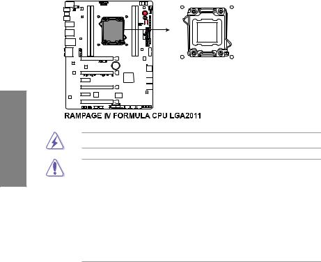
2.2.2Central Processing Unit (CPU)
The motherboard comes with a surface mount LGA2011 socket designed for the Intel® 2nd Generation Core™ i7 Processor Extreme Edition.
Ensure that all power cables are unplugged before installing the CPU.
•Upon purchase of the motherboard, ensure that the PnP cap is on the socket and the socket contacts are not bent. Contact your retailer immediately if the PnP cap is missing, or if you see any damage to the PnP cap/socket contacts/motherboard components. ASUS will shoulder the cost of repair only if the damage is shipment/ transit-related.
•Keep the cap after installing the motherboard. ASUS will process Return Merchandise
Authorization (RMA) requests only if the motherboard comes with the cap on the
LGA2011 socket.
•The product warranty does not cover damage to the socket contacts resulting from incorrect CPU installation/removal, or misplacement/loss/incorrect removal of the PnP cap.
2-4 |
Chapter 2: Hardware information |
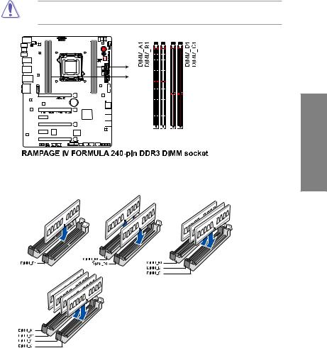
2.2.3System memory
The motherboard comes with four Double Data Rate 3 (DDR3) Dual Inline Memory Modules (DIMM) slots.
A DDR3 module is notched differently from a DDR or DDR2 module. DO NOT install a DDR or DDR2 memory module to the DDR3 slot.
Recommended memory configurations |
Chapter 2 |
|
ROG RAMPAGE IV FORMULA |
2-5 |

Memory configurations
You may install 1GB, 2GB, 4GB and 8GB unbuffered and non ECC DDR3 DIMMs into the DIMM sockets.
2 Chapter
•You may install varying memory sizes in ChannelA, Channel B, Channel C and Channel D. The system maps the total size of the lower-sized channel for the dualchannel, triple-channel and quad-channel configuration.Any excess memory from the higher-sized channel is then mapped for single-channel operation.
•Due to CPU behavior, DDR3 2200/2000/1800 MHz memory module will run at DDR3 2133/1866/1600 MHz frequency as default.
•According to Intel® spec, the max. 32GB memory capacity can be supported with DIMMs of 8GB (or above). ASUS will update QVL once the DIMMs are available on the market.
•According to Intel CPU spec, DIMM voltage below 1.65V is recommended to protect the CPU.
•Always install DIMMs with the same CAS latency. For optimum compatibility, we recommend that you obtain memory modules from the same vendor.
•Due to the memory address limitation on 32-bit Windows OS, when you install 4GB or more memory on the motherboard, the actual usable memory for the OS can be about 3GB or less. For effective use of memory, we recommend that you do any of the following:
-Use a maximum of 3GB system memory if you are using a 32-bit Windows OS.
-Install a 64-bit Windows OS when you want to install 4GB or more on the motherboard.
For more details, refer to the Microsoft® support site at http://support.microsoft.com/kb/929605/en-us.
•This motherboard does not support DIMMs made up of 512Mb (64MB) chips or less (Memory chip capacity counts in Megabit, 8 Megabit/Mb = 1 Megabyte/MB).
•The default memory operation frequency is dependent on its Serial Presence Detect (SPD), which is the standard way of accessing information from a memory module. Under the default state, some memory modules for overclocking may operate at a lower frequency than the vendor-marked value. To operate at the vendor-marked or at a higher frequency, refer to section 3.3 Extreme Tweaker menu for manual memory frequency adjustment.
•For system stability, use a more efficient memory cooling system to support a full memory load (4 DIMMs) or overclocking condition.
2-6 |
Chapter 2: Hardware information |
 Loading...