

ZYXEL GS1915-8EP, GS1915-8 User guide

Default Login Details
User’s Guide
GS1915 Series
8-port GbE Layer 2 Switch/PoE Switch
Management IP
Address
User Name admin
Password 1234
http://DHCP-assigned IP
or
192.168.1.1
Version 4.70 Edition 1, 11/2021
Copyright © 2021 Zyxel and/or its affiliates. All Rights Reserved.

IMPORTANT!
READ CAREFULLY BEFORE USE.
KEEP THIS GUIDE FOR FUTURE REFERENCE.
This is a User’s Guide for a series of products. Not all products support all firmware features. Screenshots
and graphics in this book may differ slightly from your product due to differences in your product
firmware or your computer operating system. Every effort has been made to ensure that the information
in this manual is accurate.
Related Documentation
•Quick Start Guide
The Quick Start Guide shows how to connect the Switch.
• Online Help
Click the help link for a description of the fields in the Switch menus.
• Nebula Control Center (NCC) User’s Guide
Go to the Nebula Control Center to get this User’s Guide on how to configure the Switch using
Nebula.
•More Information
Go to https://businessforum.zyxel.com for product discussions.
Go to support.zyxel.com to find other information on the Switch
.
GS1915 Series User’s Guide
2
Document Conventions
Warnings and Notes
These are how warnings and notes are shown in this guide.
Warnings tell you about things that could harm you or your device.
Note: Notes tell you other important information (for example, other things you may need to
configure or helpful tips) or recommendations.
Syntax Conventions
• All models may be referred to as the “Switch” in this guide.
• Product labels, screen names, field labels and field choices are all in bold font.
• A right angle bracket ( > ) within a screen name denotes a mouse click. For example, Basic Setting >
IP Setup > IP Configuration > Network Proxy Configuration means you first click Basic Setting in the
navigation panel, then the IP Setup sub menu, then IP Configuration and finally Network Proxy
Configuration to get to that screen.
Icons Used in Figures
Figures in this user guide may use the following generic icons. The Switch icon is not an exact
representation of your device.
Switch Generic Router Wireless Router / Access Point
Generic Switch Smart TV Desktop
Laptop IP Camera Printer
Server
GS1915 Series User’s Guide
3

Contents Overview
Contents Overview
User’s Guide ......................................................................................................................................17
Getting to Know Your Switch .............................................................................................................. 18
Hardware Installation and Connection ............................................................................................. 26
Hardware Panels .................................................................................................................................. 30
Technical Reference ........................................................................................................................35
Web Configurator ................................................................................................................................. 36
Initial Setup Example ............................................................................................................................ 60
Tutorials .................................................................................................................................................. 65
Status ...................................................................................................................................................... 73
Basic Setting .......................................................................................................................................... 79
VLAN .................................................................................................................................................... 110
Static MAC Forwarding ...................................................................................................................... 125
Static Multicast Forwarding ............................................................................................................... 127
Filtering ................................................................................................................................................. 130
Spanning Tree Protocol ...................................................................................................................... 132
Bandwidth Control ............................................................................................................................. 138
Broadcast Storm Control ................................................................................................................... 140
Mirroring ............................................................................................................................................... 142
Link Aggregation ................................................................................................................................ 144
Port Security ......................................................................................................................................... 151
Time Range ......................................................................................................................................... 154
Queuing Method ................................................................................................................................ 156
Multicast .............................................................................................................................................. 159
AAA ...................................................................................................................................................... 165
DHCP Snooping .................................................................................................................................. 173
Loop Guard ......................................................................................................................................... 184
Error-Disable ........................................................................................................................................ 187
Green Ethernet ................................................................................................................................... 194
Link Layer Discovery Protocol (LLDP) ................................................................................................ 196
Differentiated Services ....................................................................................................................... 218
DHCP .................................................................................................................................................... 222
ARP Setup ............................................................................................................................................ 234
Maintenance ...................................................................................................................................... 238
Access Control .................................................................................................................................... 251
Diagnostic ........................................................................................................................................... 273
System Log .......................................................................................................................................... 276
Syslog Setup ........................................................................................................................................ 277
GS1915 Series User’s Guide
4

Contents Overview
Cluster Management ......................................................................................................................... 280
MAC Table ........................................................................................................................................... 286
ARP Table ............................................................................................................................................ 289
Path MTU Table ................................................................................................................................... 291
Configure Clone ................................................................................................................................. 292
IPv6 Neighbor Table ........................................................................................................................... 294
Port Status ............................................................................................................................................ 296
Troubleshooting and Appendices .................................................................................................301
Troubleshooting .................................................................................................................................. 302
GS1915 Series User’s Guide
5

Table of Contents
Table of Contents
Document Conventions .................................................................. ....................................................3
Contents Overview..............................................................................................................................4
Table of Contents.................................................................................................................................6
Part I: User’s Guide.......................................................................................... 17
Chapter 1
Getting to Know Your Switch ............................................................................................................18
1.1 Introduction ..................................................................................................................................... 18
1.1.1 Management Modes ........................................................................................................... 18
1.1.2 Mode Changing ................................................................................................................... 19
1.1.3 ZON Utility ............................................................................................................................... 20
1.1.4 PoE .......................................................................................................................................... 20
1.2 Example Applications .................................................................................................................... 21
1.2.1 PoE Example Application ..................................................................................................... 21
1.2.2 Backbone Example Application ......................................................................................... 22
1.2.3 Bridging Example .................................................................................................................. 22
1.2.4 High Performance Switching Example ............................................................................... 23
1.2.5 IEEE 802.1Q VLAN Application Examples ........................................................................... 23
1.3 Ways to Manage the Switch ......................................................................................................... 24
1.4 Good Habits for Managing the Switch ........................................................................................24
Chapter 2
Hardware Installation and Connection ...........................................................................................26
2.1 Installation Scenarios ...................................................................................................................... 26
2.2 Safety Precautions .......................................................................................................................... 26
2.3 Desktop Installation Procedure ..................................................................................................... 26
2.4 Wall Mounting ................................................................................................................................. 27
2.4.1 Installation Requirements ..................................................................................................... 27
Chapter 3
Hardware Panels................................................................................................................................30
3.1 Front Panel Connections ............................................................................................................... 30
3.1.1 Gigabit Ethernet Ports ........................................................................................................... 30
3.1.2 PoE .......................................................................................................................................... 31
3.2 Rear Panel ....................................................................................................................................... 31
GS1915 Series User’s Guide
6

Table of Contents
3.2.1 Grounding .............................................................................................................................. 32
3.2.2 Power Connection ................................................................................................................ 33
3.3 LEDs .................................................................................................................................................. 34
Part II: Technical Reference........................................................................... 35
Chapter 4
Web Configurator...............................................................................................................................36
4.1 Overview ......................................................................................................................................... 36
4.2 System Login .................................................................................................................................... 36
4.3 Zyxel One Network (ZON) Utility .................................................................................................... 40
4.3.1 Requirements ......................................................................................................................... 40
4.3.2 Run the ZON Utility ................................................................................................................. 40
4.4 Wizard .............................................................................................................................................. 44
4.4.1 Basic ....................................................................................................................................... 44
4.4.2 Protection .............................................................................................................................. 48
4.4.3 VLAN ....................................................................................................................................... 51
4.4.4 QoS ......................................................................................................................................... 52
4.5 Web Configurator Layout .............................................................................................................. 53
4.5.1 Change Your Password ........................................................................................................ 57
4.6 Save Your Configuration ................................................................................................................ 57
4.7 Switch Lockout ................................................................................................................................ 58
4.8 Reset the Switch ............................................................................................................................. 58
4.8.1 Restore Button ....................................................................................................................... 58
4.9 Log Out of the Web Configurator ................................................................................................ 59
4.10 Help ................................................................................................................................................ 59
Chapter 5
Initial Setup Example.........................................................................................................................60
5.1 Overview ......................................................................................................................................... 60
5.1.1 Create a VLAN ...................................................................................................................... 60
5.1.2 Set Port VID ............................................................................................................................ 61
5.1.3 Configure Switch Management IP Address ....................................................................... 62
Chapter 6
Tutorials...............................................................................................................................................65
6.1 Overview ......................................................................................................................................... 65
6.2 How to Use DHCPv4 Snooping on the Switch ............................................................................. 65
6.3 How to Use DHCPv4 Relay on the Switch .................................................................................... 68
6.3.1 DHCP Relay Tutorial Introduction ........................................................................................ 68
6.3.2 Create a VLAN ...................................................................................................................... 69
GS1915 Series User’s Guide
7

Table of Contents
6.3.3 Configure DHCPv4 Relay ..................................................................................................... 71
6.3.4 Troubleshooting ..................................................................................................................... 71
Chapter 7
Status...................................................................................................................................................73
7.1 Overview ......................................................................................................................................... 73
7.1.1 What You Can Do ................................................................................................................. 73
7.2 Status ................................................................................................................................................ 73
7.2.1 Neighbor Screen ................................................................................................................... 75
7.2.2 Neighbor Detail ..................................................................................................................... 76
Chapter 8
Basic Setting.......................................................................................................................................79
8.1 Overview ......................................................................................................................................... 79
8.1.1 What You Can Do ................................................................................................................. 79
8.2 System Information ......................................................................................................................... 79
8.3 General Setup ................................................................................................................................. 80
8.4 Switch Setup .................................................................................................................................... 82
8.4.1 Introduction to VLANs ........................................................................................................... 82
8.4.2 Setting up ............................................................................................................................... 83
8.5 IP Setup ............................................................................................................................................ 84
8.5.1 IP Interfaces ........................................................................................................................... 84
8.5.2 IP Status .................................................................................................................................. 85
8.5.3 IP Status Details ...................................................................................................................... 85
8.5.4 IP Configuration .................................................................................................................... 87
8.5.5 Network Proxy Configuration ............................................................................................... 89
8.6 Port Setup ........................................................................................................................................ 90
8.7 PoE Status ........................................................................................................................................ 91
8.7.1 PoE Time Range Setup ......................................................................................................... 93
8.7.2 PoE Setup ............................................................................................................................... 94
8.8 Interface Setup ............................................................................................................................... 96
8.9 IPv6 ................................................................................................................................................... 97
8.9.1 IPv6 Status .............................................................................................................................. 97
8.9.2 IPv6 Interface Status ............................................................................................................. 98
8.9.3 IPv6 Configuration .............................................................................................................. 100
8.9.4 IPv6 Global Setup ................................................................................................................ 101
8.9.5 IPv6 Interface Setup ............................................................................................................ 102
8.9.6 IPv6 Link-Local Address Setup ............................................................................................103
8.9.7 IPv6 Global Address Setup ................................................................................................. 104
8.9.8 IPv6 Neighbor Discovery Setup ......................................................................................... 105
8.9.9 IPv6 Neighbor Setup ........................................................................................................... 106
8.9.10 DHCPv6 Client Setup ........................................................................................................ 107
8.10 Cloud Management .................................................................................................................. 108
GS1915 Series User’s Guide
8

Table of Contents
8.10.1 Nebula Center Control Discovery ................................................................................... 108
8.10.2 Nebula Switch Registration ..............................................................................................109
Chapter 9
VLAN..................................................................................................................................................110
9.1 Overview ....................................................................................................................................... 110
9.1.1 What You Can Do ............................................................................................................... 110
9.1.2 What You Need to Know ................................................................................................... 110
9.2 Introduction to IEEE 802.1Q Tagged VLANs ............................................................................... 110
9.3 VLAN Status ................................................................................................................................... 112
9.3.1 VLAN Details ........................................................................................................................ 113
9.4 VLAN Configuration ..................................................................................................................... 114
9.5 Configure a Static VLAN .............................................................................................................. 115
9.6 Configure VLAN Port Settings ...................................................................................................... 116
9.7 Voice VLAN ................................................................................................................................... 117
9.8 MAC Based VLAN ......................................................................................................................... 119
9.9 Vendor ID Based VLAN ................................................................................................................ 120
9.10 Port-Based VLAN Setup .............................................................................................................. 122
9.10.1 Configure a Port-Based VLAN ......................................................................................... 122
Chapter 10
Static MAC Forwarding....................................................................................................................125
10.1 Overview ..................................................................................................................................... 125
10.1.1 What You Can Do ............................................................................................................. 125
10.2 Configure Static MAC Forwarding ...........................................................................................125
Chapter 11
Static Multicast Forwarding.............................................................................................................127
11.1 Static Multicast Forwarding Overview ..................................................................................... 127
11.1.1 What You Can Do ............................................................................................................. 127
11.1.2 What You Need To Know ................................................................................................. 127
11.2 Configure Static Multicast Forwarding .....................................................................................128
Chapter 12
Filtering..............................................................................................................................................130
12.1 Filtering Overview ....................................................................................................................... 130
12.1.1 What You Can Do ............................................................................................................. 130
12.2 Configure a Filtering Rule .......................................................................................................... 130
Chapter 13
Spanning Tree Protocol ...................................................................................................................132
13.1 Spanning Tree Protocol Overview ............................................................................................ 132
13.1.1 What You Can Do ............................................................................................................. 132
GS1915 Series User’s Guide
9

Table of Contents
13.1.2 What You Need to Know ................................................................................................. 132
13.2 Rapid Spanning Tree Protocol Status .......................................................................................134
13.3 Configure Rapid Spanning Tree Protocol ................................................................................ 135
Chapter 14
Bandwidth Control...........................................................................................................................138
14.1 Bandwidth Control Overview .................................................................................................... 138
14.1.1 What You Can Do ............................................................................................................. 138
14.2 Bandwidth Control Setup .......................................................................................................... 138
Chapter 15
Broadcast Storm Control .................................................................................................................140
15.1 Broadcast Storm Control Overview ..........................................................................................140
15.1.1 What You Can Do ............................................................................................................. 140
15.2 Broadcast Storm Control Setup ................................................................................................ 140
Chapter 16
Mirroring............................................................................................................................................142
16.1 Mirroring Overview ..................................................................................................................... 142
16.2 Port Mirroring Setup .................................................................................................................... 142
Chapter 17
Link Aggregation .................................... .... .... ... ............................................ .... .... ..........................144
17.1 Link Aggregation Overview ....................................................................................................... 144
17.1.1 What You Can Do ............................................................................................................. 144
17.1.2 What You Need to Know ................................................................................................. 144
17.2 Link Aggregation Status ............................................................................................................. 145
17.3 Link Aggregation Setting ........................................................................................................... 146
17.3.1 Link Aggregation Control Protocol ................................................................................. 148
17.4 Technical Reference .................................................................................................................. 149
17.4.1 Static Trunking Example ................................................................................................... 149
Chapter 18
Port Security......................................................................................................................................151
18.1 Port Security Overview ............................................................................................................... 151
18.2 About Port Security ..................................................................................................................... 151
18.3 Port Security Setup ...................................................................................................................... 151
Chapter 19
Time Range.......................................................................................................................................154
19.1 Time Range Overview ................................................................................................................ 154
19.1.1 What You Can Do ............................................................................................................. 154
19.2 Configuring Time Range ............................................................................................................ 154
GS1915 Series User’s Guide
10

Table of Contents
Chapter 20
Queuing Method..............................................................................................................................156
20.1 Queuing Method Overview ...................................................................................................... 156
20.1.1 What You Can Do ............................................................................................................. 156
20.1.2 What You Need to Know ................................................................................................. 156
20.2 Configuring Queuing ................................................................................................................. 157
Chapter 21
Multicast............................................................................................................................................159
21.1 Multicast Overview ..................................................................................................................... 159
21.1.1 What You Can Do ............................................................................................................. 159
21.1.2 What You Need to Know ................................................................................................. 159
21.2 Multicast Setup ........................................................................................................................... 160
21.3 IPv4 Multicast Status ................................................................................................................... 160
21.3.1 IGMP Snooping .................................................................................................................. 161
21.3.2 IGMP Snooping VLAN ....................................................................................................... 163
Chapter 22
AAA...................................................................................................................................................165
22.1 Authentication, Authorization and Accounting (AAA) ......................................................... 165
22.1.1 What You Can Do ............................................................................................................. 165
22.1.2 What You Need to Know ................................................................................................. 165
22.2 AAA Screens ............................................................................................................................... 166
22.3 RADIUS Server Setup ................................................................................................................... 166
22.4 AAA Setup ................................................................................................................................... 168
22.5 Technical Reference .................................................................................................................. 170
22.5.1 Vendor Specific Attribute ................................................................................................ 170
22.5.2 Supported RADIUS Attributes ........................................................................................... 171
22.5.3 Attributes Used for Authentication .................................................................................. 172
Chapter 23
DHCP Snooping................................................................................................................................173
23.1 DHCP Snooping Overview ......................................................................................................... 173
23.1.1 What You Can Do ............................................................................................................. 173
23.2 DHCP Snooping .......................................................................................................................... 173
23.3 DHCP Snooping Configure ........................................................................................................ 176
23.3.1 DHCP Snooping Port Configure ...................................................................................... 178
23.3.2 DHCP Snooping VLAN Configure .................................................................................... 179
23.3.3 DHCP Snooping VLAN Port Configure ............................................................................ 180
23.4 Technical Reference .................................................................................................................. 181
23.4.1 DHCP Snooping Overview ............................................................................................... 181
GS1915 Series User’s Guide
11

Table of Contents
Chapter 24
Loop Guard ......................................................................................................................................184
24.1 Loop Guard Overview ............................................................................................................... 184
24.1.1 What You Can Do ............................................................................................................. 184
24.1.2 What You Need to Know ................................................................................................. 184
24.2 Loop Guard Setup ...................................................................................................................... 186
Chapter 25
Error-Disable.....................................................................................................................................187
25.1 Error-Disable Overview ............................................................................................................... 187
25.1.1 CPU Protection Overview ................................................................................................ 187
25.1.2 Error-Disable Recovery Overview .................................................................................... 187
25.1.3 What You Can Do ............................................................................................................. 187
25.2 Error-Disable Settings .................................................................................................................. 188
25.3 Error-Disable Status ..................................................................................................................... 188
25.4 CPU Protection Configuration ................................................................................................... 190
25.5 Error-Disable Detect Configuration .......................................................................................... 191
25.6 Error-Disable Recovery Configuration ......................................................................................192
Chapter 26
Green Ethernet.................................................................. .... ...........................................................194
26.1 Green Ethernet Overview .......................................................................................................... 194
26.2 Configuring Green Ethernet ...................................................................................................... 194
Chapter 27
Link Layer Discovery Protocol (LLDP) .............................................................................................196
27.1 LLDP Overview ............................................................................................................................ 196
27.2 LLDP-MED Overview ................................................................................................................... 197
27.3 LLDP Settings ............................................................................................................................... 198
27.4 LLDP Local Status ........................................................................................................................ 199
27.4.1 LLDP Local Port Status Detail ...........................................................................................200
27.5 LLDP Remote Status .................................................................................................................... 203
27.5.1 LLDP Remote Port Status Detail ....................................................................................... 204
27.6 LLDP Configuration ..................................................................................................................... 210
27.6.1 LLDP Configuration Basic TLV Setting .............................................................................. 211
27.6.2 LLDP Configuration Org-specific TLV Setting ................................................................. 212
27.7 LLDP-MED Configuration ............................................................................................................ 213
27.8 LLDP-MED Network Policy .......................................................................................................... 213
27.9 LLDP-MED Location .................................................................................................................... 215
Chapter 28
Differentiated Services ....................................................................................................................218
28.1 DiffServ Overview ....................................................................................................................... 218
GS1915 Series User’s Guide
12

Table of Contents
28.1.1 What You Need to Know ................................................................................................. 218
28.2 Activating DiffServ ...................................................................................................................... 219
28.3 DSCP-to-IEEE 802.1p Priority Settings ......................................................................................... 220
28.3.1 Configuring DSCP Settings ...............................................................................................221
Chapter 29
DHCP .................................................................................................................................................222
29.1 DHCP Overview .......................................................................................................................... 222
29.1.1 What You Can Do ............................................................................................................. 222
29.1.2 What You Need to Know ................................................................................................. 222
29.2 DHCP Configuration ................................................................................................................... 223
29.3 DHCPv4 Status ............................................................................................................................ 223
29.4 DHCPv4 Relay ............................................................................................................................. 223
29.4.1 DHCPv4 Relay Agent Information ................................................................................... 224
29.4.2 DHCPv4 Option 82 Profile ................................................................................................. 225
29.4.3 Configuring DHCPv4 Global Relay ................................................................................. 226
29.4.4 Configure DHCPv4 Global Relay Port ............................................................................ 227
29.4.5 Global DHCP Relay Configuration Example .................................................................. 228
29.4.6 DHCPv4 VLAN Setting ....................................................................................................... 229
29.4.7 Configure DHCPv4 VLAN Port ......................................................................................... 230
29.4.8 Example: DHCP Relay for Two VLANs ............................................................................. 231
29.5 DHCPv6 Relay ............................................................................................................................. 232
Chapter 30
ARP Setup..........................................................................................................................................234
30.1 ARP Overview ............................................................................................................................. 234
30.1.1 What You Can Do ............................................................................................................. 234
30.1.2 What You Need to Know ................................................................................................. 234
30.2 ARP Setup .................................................................................................................................... 236
30.2.1 ARP Learning ..................................................................................................................... 236
Chapter 31
Maintenance....................................................................................................................................238
31.1 Overview ..................................................................................................................................... 238
31.1.1 What You Can Do ............................................................................................................. 238
31.2 Maintenance Settings ................................................................................................................ 238
31.2.1 Erase Running-Configuration ........................................................................................... 240
31.2.2 Save Configuration ........................................................................................................... 240
31.2.3 Reboot System .................................................................................................................. 240
31.2.4 Factory Default .................................................................................................................. 241
31.2.5 Custom Default ................................................................................................................. 241
31.3 Firmware Upgrade ...................................................................................................................... 242
31.4 Restore Configuration ................................................................................................................ 243
GS1915 Series User’s Guide
13

Table of Contents
31.5 Backup Configuration ................................................................................................................ 244
31.6 Tech-Support ............................................................................................................................... 244
31.6.1 Tech-Support Download .................................................................................................. 246
31.7 Certificates .................................................................................................................................. 246
31.7.1 HTTPS Certificates .............................................................................................................. 247
31.8 Technical Reference .................................................................................................................. 248
31.8.1 FTP Command Line ........................................................................................................... 248
31.8.2 Filename Conventions ...................................................................................................... 248
31.8.3 FTP Command Line Procedure ........................................................................................ 249
31.8.4 GUI-based FTP Clients ....................................................................................................... 250
31.8.5 FTP Restrictions ................................................................................................................... 250
Chapter 32
Access Control.................................................................................................................................251
32.1 Access Control Overview .......................................................................................................... 251
32.1.1 What You Can Do ............................................................................................................. 251
32.2 Access Control Main Settings .................................................................................................... 251
32.3 Configure SNMP .......................................................................................................................... 252
32.3.1 Configure SNMP Trap Group ........................................................................................... 253
32.3.2 Enable or Disable Sending of SNMP Traps on a Port ..................................................... 254
32.3.3 Configure SNMP User ........................................................................................................ 255
32.4 Set Up Login Accounts ............................................................................................................... 257
32.5 Service Access Control .............................................................................................................. 258
32.6 Remote Management ............................................................................................................... 259
32.7 Account Security ........................................................................................................................ 260
32.8 Technical Reference .................................................................................................................. 262
32.8.1 About SNMP ....................................................................................................................... 262
32.8.2 SSH Overview ..................................................................................................................... 265
32.8.3 Introduction to HTTPS ........................................................................................................ 267
32.8.4 Google Chrome Warning Messages .............................................................................. 271
Chapter 33
Diagnostic.........................................................................................................................................273
33.1 Overview ..................................................................................................................................... 273
33.2 Diagnostic ................................................................................................................................... 273
Chapter 34
System Log........................................................................................................................................276
34.1 Overview ..................................................................................................................................... 276
34.2 System Log .................................................................................................................................. 276
Chapter 35
Syslog Setup .....................................................................................................................................277
GS1915 Series User’s Guide
14

Table of Contents
35.1 Syslog Overview .......................................................................................................................... 277
35.1.1 What You Can Do ............................................................................................................. 277
35.2 Syslog Setup ................................................................................................................................ 277
Chapter 36
Cluster Management.......................................................................................................................280
36.1 Cluster Management Overview ...............................................................................................280
36.1.1 What You Can Do ............................................................................................................. 280
36.2 Cluster Management Status ..................................................................................................... 281
36.3 Clustering Management Configuration .................................................................................. 282
36.4 Technical Reference .................................................................................................................. 283
36.4.1 Cluster Member Switch Management ........................................................................... 283
Chapter 37
MAC Table........................................................................................................................................286
37.1 MAC Table Overview ................................................................................................................. 286
37.1.1 What You Can Do ............................................................................................................. 286
37.1.2 What You Need to Know ................................................................................................. 286
37.2 Viewing the MAC Table ............................................................................................................. 287
Chapter 38
ARP Table..........................................................................................................................................289
38.1 Overview ..................................................................................................................................... 289
38.1.1 What You Can Do ............................................................................................................. 289
38.1.2 What You Need to Know ................................................................................................. 289
38.2 Viewing the ARP Table ............................................................................................................... 289
Chapter 39
Path MTU Table.................................................................................................................................291
39.1 Path MTU Overview .................................................................................................................... 291
39.2 Viewing the Path MTU Table ..................................................................................................... 291
Chapter 40
Configure Clone.................... .... ... ............................................ .... .... ... .... .........................................292
40.1 Overview ..................................................................................................................................... 292
40.2 Configure Clone ......................................................................................................................... 292
Chapter 41
IPv6 Neighbor Table.........................................................................................................................294
41.1 IPv6 Neighbor Table Overview .................................................................................................. 294
41.2 Viewing the IPv6 Neighbor Table ............................................................................................. 294
Chapter 42
Port Status .........................................................................................................................................296
GS1915 Series User’s Guide
15

Table of Contents
42.1 Overview ..................................................................................................................................... 296
42.2 Port Status .................................................................................................................................... 296
42.2.1 Port Details ......................................................................................................................... 297
42.2.2 Port Utilization .................................................................................................................... 300
Part III: Troubleshooting and Appendices..................................................301
Chapter 43
Troubleshooting................................................................................................................................302
43.1 Power, Hardware Connections, and LEDs ............................................................................... 302
43.2 Switch Access and Login ........................................................................................................... 303
43.3 Switch Configuration .................................................................................................................. 305
Appendix A Customer Support ..................................................................................................... 306
Appendix B Common Services...................................................................................................... 311
Appendix C IPv6.............................................................................................................................. 314
Appendix D Legal Information ...................................................................................................... 323
Index.................................................................................................................................................328
GS1915 Series User’s Guide
16

PART I
User’s Guide
17

CHAPTER 1
Getting to Know Your Switch
1.1 Introduction
This chapter introduces the main features and applications of the Switch.
The GS1915 Series consists of the following models:
• GS1915-8
• GS1915-8EP
References to PoE models in this User's Guide only apply to GS1915-8EP.
The Switch is a layer-2 Ethernet switch that only does switching.
All models are referred to as the “Switch” in this guide.
The Switch supports NebulaFlex for hybrid mode which can set the Switch to operate in either
standalone or Nebula cloud management mode. When the Switch is in standalone mode, it can be
configured and managed by the Web Configurator. When the Switch is in Nebula cloud management
mode, it can be managed and provisioned by the Zyxel Nebula Control Center (NCC).
The following table describes the hardware features of the Switch by model.
Table 1 GS1915 Series Comparison Table
FEATURES GS1915-8 GS1915-8EP
Number of 10/100/1000 Mbps
Ethernet ports
Number of 10/100/1000 Mbps PoE
ports
Total system ports 8 8
Rubber feet for desktop placement Yes Yes
Wall-mount Yes Yes
1.1.1 Management Modes
NebulaFlex means you can set the Switch to operate in either standalone or cloud mode (but not both
at the same time).
88
08
Use the Web Configurator to configure and manage the Switch directly in standalone mode or use
Nebula Control Center (NCC) to configure and manage the Switch in cloud mode. The Nebula Control
Center (NCC) is an alternative cloud-based network management system that allows you to remotely
manage and monitor the Switch. You may also access a minimized version of the Web Configurator in
cloud mode.
GS1915 Series User’s Guide
18

Nebula Cloud Management
To have Nebula manage the Switch, you must first register it at the Nebula web portal at https://
nebula.zyxel.com, and ensure that Nebula Control Center Discovery is enabled in Basic Setting > Cloud
Management > Nebula Control Center Discovery in the Switch Web Configurator.
Note: See the Switch’s datasheet for the feature differences between standalone and
Nebula cloud management modes. You can find the Switch’s datasheet at the Zyxel
website.
See the NCC (Nebula Control Center) User’s Guide for how to configure the Switch using Nebula.
1.1.2 Mode Changing
This section describes how to change the Switch’s management mode.
Note: If you change the Switch’s management mode from standalone mode to Nebula-
managed mode, the configuration settings of the
you have configured in Nebula.
Chapter 1 Getting to Know Your Switch
Switch will be overwritten with what
Note: If you change the
standalone mode, the
Switch’s management mode from Nebula-managed mode to
Switch will reset to its factory-default settings.
From Standalone to Nebula Cloud Management
To manage your Switch through Nebula, connect the Switch to the Internet, and register it to a site and
organization at the Nebula web portal (https://nebula.zyxel.com).
See the following steps or the Switch Quick Start Guide for how to do device registration.
Go to the NCC to Register the Switch
1 Go to the Nebula web portal in one of three ways.
• Type https://nebula.zyxel.com in a supported web browser. See the Nebula User’s Guide for more
information about supported browsers.
• Click Visit Nebula in the Switch’s login page.
• Click the Nebula icon in the upper right of the Switch’s Web Configurator.
2 Click Get Started in the Nebula web portal. Enter your myZyxel account information. You will be
redirected to another screen where you can sign up for a myZyxel account if you do not have one.
3 Create an organization and a site or select an existing site using the Nebula setup wizard.
4 Register the Switch by entering its MAC address and serial number and assign it to the site. The serial
number and MAC address can be found in the Status screen or the device back label on the Switch.
Use the Zyxel Nebula Mobile App to Register the Switch
1 Download and open the Zyxel Nebula Mobile app in your mobile device. Click Sign Up to create a
myZyxel account or enter your existing account information to log in.
2 Create an organization and site, or select an existing site using the Zyxel Nebula Mobile app.
GS1915 Series User’s Guide
19

3 Select a site and scan the Switch's QR code to add it to the site. You can find the QR code:
• On a label on the Switch or
• On its box or
• In the Web Configurator at Basic Setting > Cloud Management > Nebula Switch Registration.
See Section 3.3 on page 34 for more information about the CLOUD LED or Section 7.2 on page 73 for
more information about the Hybrid Mode field in the Status screen to see if the Switch goes into Nebula
cloud management mode successfully.
Note: The Switch goes into Nebula-managed mode automatically after it can access the
Nebula web portal and is successfully registered there. Its login password and settings
are then overwritten with what you have configured in the Nebula web portal.
From Nebula-managed to Standalone
To return to direct management standalone mode, just remove (unregister) the Switch from the
organization or site in the Nebula web portal. The
settings.
1.1.3 ZON Utility
Chapter 1 Getting to Know Your Switch
Switch will reboot and restore the factory default
With its built-in Web Configurator, including the Neighbor Management feature (Section 7.2.1 on page
75), viewing, managing and configuring the Switch and its neighboring devices is simplified.
In addition, Zyxel offers a proprietary software program called Zyxel One Network (ZON) Utility, it is a
utility tool that assists you to set up and maintain network devices in a more simple and efficient way.
You can download the ZON Utility at www.zyxel.com and install it on a PC (Windows operation system).
For more information on ZON Utility see Section 4.3 on page 40.
1.1.4 PoE
The Switch is a Power Sourcing Equipment (PSE) because it provides a source of power through its
Ethernet ports. Each device that receives power through an Ethernet port is a Powered Device (PD).
The Switch can adjust the power supplied to each PD according to the PoE standard the PD supports.
PoE standards are:
• IEEE 802.3af Power over Ethernet (PoE)
• IEEE 802.3at Power over Ethernet (PoE) +
The following table describes the PoE features of the Switch by model.
Table 2 GS1915 Series Models and PoE Features
POE FEATURES GS1915-8EP
IEEE 802.3af PoE Yes
IEEE 802.3at PoE+ Yes
Power Management Mode Consumption mode (default) / Classification mode
PoE Power Budget 60 W
GS1915 Series User’s Guide
20
Chapter 1 Getting to Know Your Switch
Table 3 PoE Standards
PoE FEATURES PoE PoE+
IEEE Standard IEEE 802.3af IEEE 802.3at
PoE Type Type 1 Type 2
Switch Port Power
Maximum Power Per Port 15.4 W 30 W
Port Voltage Range 44 – 57 V 50 – 57 V
Cables
Twisted Pairs Used 2-pair 2-pair
Supported Cables Cat3 or better Cat5 or better
1.2 Example Applications
This section shows a few examples of using the Switch in various network environments. Note that the
Switch in the figure is just an example Switch and not your actual Switch.
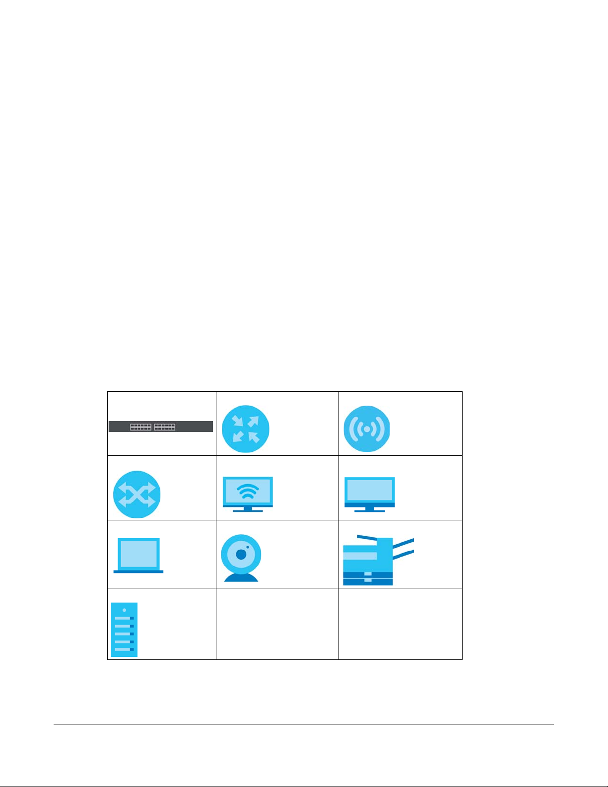
1.2.1 PoE Example Application
The following example figure shows a Switch supplying PoE (Power over Ethernet) to Powered Devices
(PDs) such as an IP camera, a wireless router, an IP telephone and a general outdoor router that are not
within reach of a power outlet.
Figure 1 PoE Example Application
GS1915 Series User’s Guide
21
Chapter 1 Getting to Know Your Switch
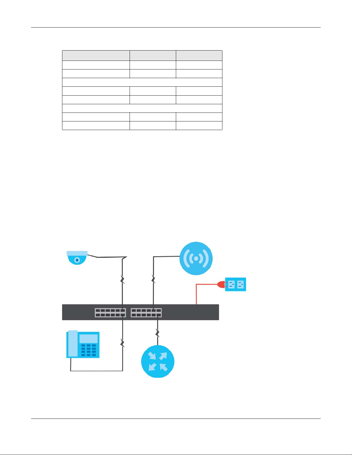
1.2.2 Backbone Example Application
The Switch is an ideal solution for small networks where rapid growth can be expected in the near future.
The Switch can be used standalone for a group of heavy traffic users. You can connect computers and
servers directly to the Switch’s port or connect other switches to the Switch.
In this example, all computers can share high-speed applications on the server. To expand the network,
simply add more networking devices such as switches, routers, computers, print servers, and so on.
Figure 2 Backbone Application
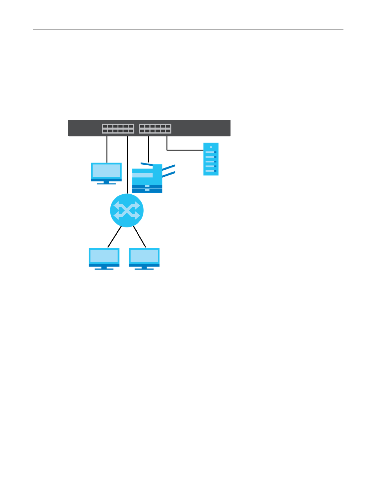
1.2.3 Bridging Example
In this example, the Switch connects different company departments (RD and Sales) to the corporate
backbone. It can alleviate bandwidth contention and eliminate server and network bottlenecks. All
users that need high bandwidth can connect to high-speed department servers through the Switch.
You can provide a super-fast uplink connection by using a Gigabit Ethernet or SFP port on the Switch.
Moreover, the Switch eases supervision and maintenance by allowing network managers to centralize
multiple servers at a single location.
GS1915 Series User’s Guide
22
Chapter 1 Getting to Know Your Switch
Figure 3 Bridging Application
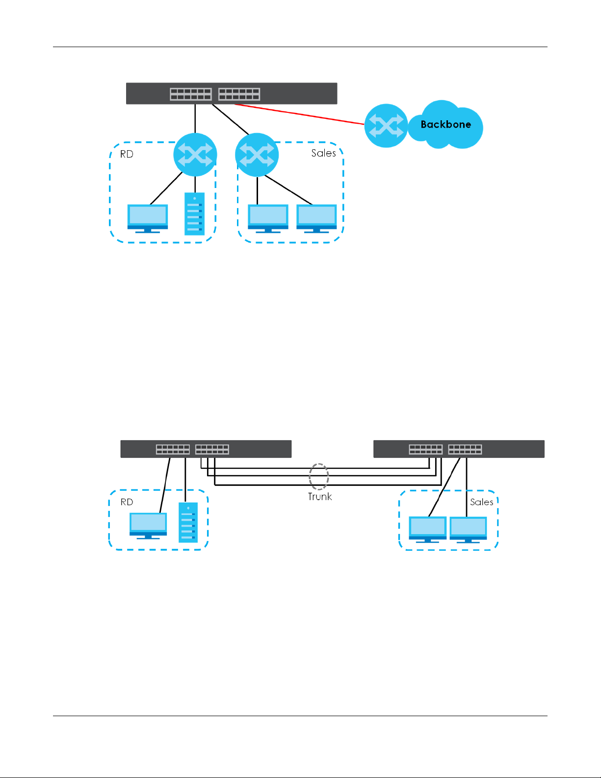
1.2.4 High Performance Switching Example
The Switch is ideal for connecting two networks that need high bandwidth. In the following example, use
link aggregation (trunking) to connect these two networks.
Switching to higher-speed LANs such as ATM (Asynchronous Transmission Mode) is not feasible for most
people due to the expense of replacing all existing Ethernet cables and adapter cards, restructuring
your network and complex maintenance. The Switch can provide the same bandwidth as ATM at much
lower cost while still being able to use existing adapters and switches. Moreover, the current LAN
structure can be retained as all ports can freely communicate with each other.
This helps you switch to higher-speed LANs without the need for replacing all existing Ethernet cables
and adapter cards, restructuring your network and complex maintenance.
Figure 4 High Performance Switched Workgroup Application
1.2.5 IEEE 802.1Q VLAN Application Examples
A VLAN (Virtual Local Area Network) allows a physical network to be partitioned into multiple logical
networks. Stations on a logical network belong to one or more groups. With VLAN, a station cannot
directly talk to or hear from stations that are not in the same groups unless such traffic first goes through
a router.
GS1915 Series User’s Guide
23
Chapter 1 Getting to Know Your Switch
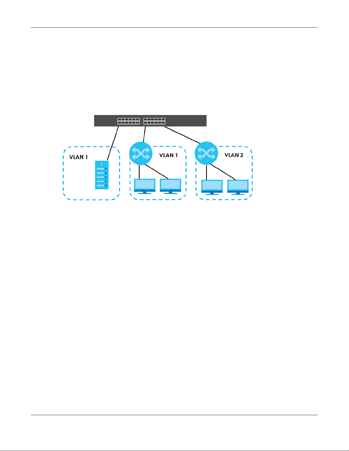
1.2.5.1 Tag-based VLAN Example
Ports in the same VLAN group share the same frame broadcast domain thereby increase network
performance through reduced broadcast traffic. VLAN groups can be modified at any time by adding,
moving or changing ports without any re-cabling.
Shared resources such as a server can be used by all ports in the same VLAN as the server. In the
following figure only ports that need access to the server need to be part of VLAN 1. Ports can belong to
other VLAN groups too.
Figure 5 Shared Server Using VLAN Example
1.3 Ways to Manage the Switch
Use any of the following methods to manage the Switch.
• NCC (Zyxel Nebula Control Center). With the NCC, you can remotely manage and monitor the
Switch through a cloud-based network management system. See the NCC User’s Guide for detailed
information about how to access the NCC and manage your Switch through the NCC. See the NCC
User’s Guide for how to configure Nebula managed devices.
• Web Configurator. This is recommended for everyday management of the Switch using a (supported)
web browser. See Chapter 4 on page 36.
• FTP. Use File Transfer Protocol for firmware upgrades and configuration backup or restore. See Section
31.8.1 on page 248.
• SNMP. The Switch can be monitored and/or managed by an SNMP manager. See Section 32.8.1 on
page 262.
• Cluster Management. Cluster Management allows you to manage multiple switches through one
switch, called the cluster manager. See Chapter 36 on page 280.
• ZON Utility. ZON Utility is a program designed to help you deploy and perform initial setup on a
network more efficiently. See Section 4.3 on page 40.
1.4 Good Habits for Managing the Switch
Do the following regularly to make the Switch more secure and to manage the Switch more effectively.
GS1915 Series User’s Guide
24

Chapter 1 Getting to Know Your Switch
• Change the password. Use a password that is not easy to guess and that consists of different types of
characters, such as numbers and letters.
• Write down the password and put it in a safe place.
• Back up the configuration (and make sure you know how to restore it). Restoring an earlier working
configuration may be useful if the device becomes unstable or even crashes. If you forget your
password, you will have to reset the Switch to its factory default settings. If you backed up an earlier
configuration file, you would not have to totally re-configure the Switch. You could simply restore your
last configuration.
GS1915 Series User’s Guide
25

Hardware Installation and
2.1 Installation Scenarios
This chapter shows you how to install and connect the Switch.
The Switch can be:
• Placed on a desktop.
• Wall-mounted on a wall.
CHAPTER 2
Connection
2.2 Safety Precautions
Please observe the following before using the Switch:
• It is recommended to ask an authorized technician to attach the Switch on a desk or to the rack or
wall. Use the proper screws to prevent damage to the Switch. See the Installation Requirements
sections in this chapter to know the types of screws and screwdrivers for each mounting method.
• Make sure there is at least 2 cm of clearance on the top and bottom of the Switch, and at least 5 cm
of clearance on all four sides of the Switch. This allows air circulation for cooling.
• Do NOT block the ventilation holes nor store cables or power cords on the Switch. Allow clearance for
the ventilation holes to prevent your Switch from overheating. This is especially crucial when your
Switch does not have fans. Overheating could affect the performance of your Switch, or even
damage it.
• The surface of the Switch could be hot when it is functioning. Do NOT put your hands on it. You may
get burned. This could happen especially when you are using a fanless Switch.
• The Switches with fans are not suitable for use in locations where children are likely to be present.
To start using the Switch, simply connect the power cables to turn it on.
2.3 Desktop Installation Procedure
1 Make sure the Switch is clean and dry.
2 Remove the adhesive backing from the rubber feet.
GS1915 Series User’s Guide
26
Chapter 2 Hardware Installation and Connection
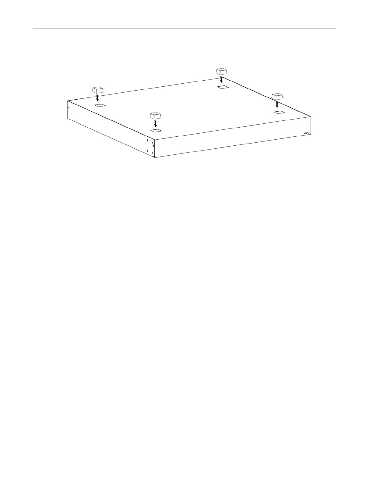
3 Attach the rubber feet to each corner on the bottom of the Switch. These rubber feet help protect the
Switch from shock or vibration and ensure space between devices when stacking.
Figure 6 Attaching Rubber Feet
4 Set the Switch on a smooth, level surface strong enough to support the weight of the Switch and the
connected cables. Make sure there is a power outlet nearby.
Cautions:
• Avoid stacking fanless Switches to prevent overheating.
• Ensure enough clearance around the Switch to allow air circulation for cooling.
• Do NOT remove the rubber feet as it provides space for air circulation.
2.4 Wall Mounting
The Switch can be mounted on a wall. You may need screw anchors if mounting on a concrete or brick
wall.
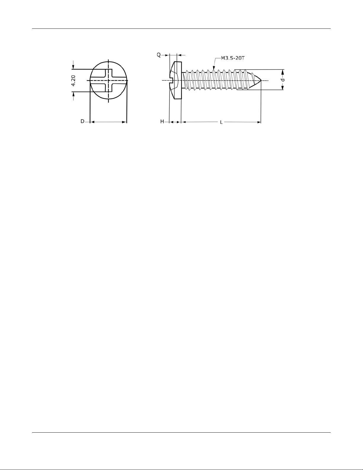
2.4.1 Installation Requirements
• Use screws with 6 mm – 8 mm (0.24" – 0.31") wide heads.
• The distance between the screws: 176 mm.
The following figure shows the screw specifications used for wall mounting.
• D = 7.00 mm
• H = 2.00 mm
• L= 15.50 mm
• d = 3.50 mm
GS1915 Series User’s Guide
27
Chapter 2 Hardware Installation and Connection
Do the following to attach your Switch to a wall.
1 Select a position free of obstructions on a wall strong enough to hold the weight of the Switch.
2 Mark two holes on the wall at the appropriate distance apart for the screws.
WARNING! Be careful to avoid damaging pipes or cables located inside
the wall when drilling holes for the screws.
3 If using screw anchors, drill two holes for the screw anchors into the wall. Push the anchors into the full
depth of the holes, then insert the screws into the anchors. Do NOT insert the screws all the way in –
leave a small gap of about 0.5 cm.
If not using screw anchors, use a screwdriver to insert the screws into the wall. Do NOT insert the screws
all the way in – leave a gap of about 0.5 cm.
4 Make sure the screws are fastened well enough to hold the weight of the Switch with the connection
cables.
5 Align the holes on the back of the Switch with the screws on the wall. Hang the Switch on the screws.
Note: Make sure there is enough clearance between the wall and the Switch to allow
ventilation.
GS1915 Series User’s Guide
28
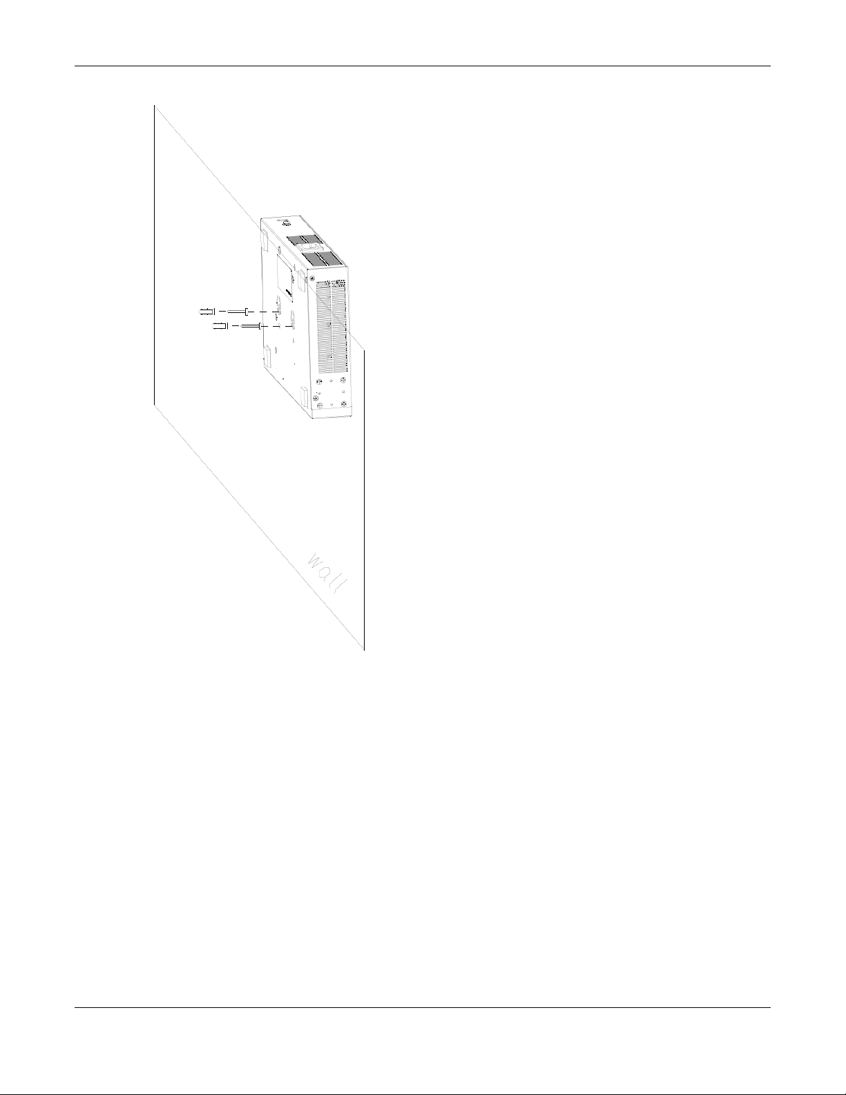
Chapter 2 Hardware Installation and Connection
WARNING! The Switch should be wall-mounted horizontally, and make sure
the front panel is facing down. The Switch's side panels with ventilation slots
should not be facing up or down as this position is less safe.
GS1915 Series User’s Guide
29
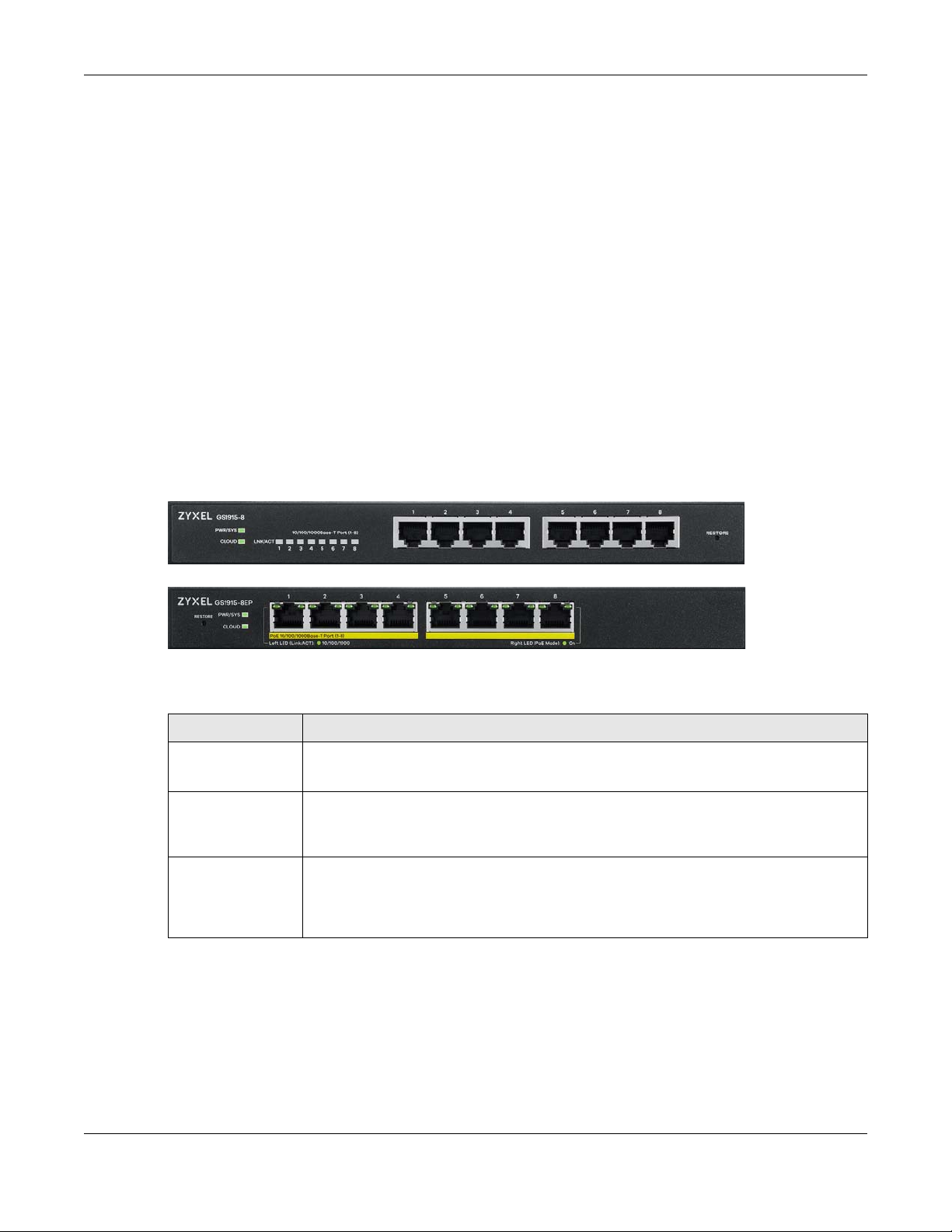
Chapter 3 Hardware Panels
Hardware Panels
This chapter describes the front panel and rear panel of the Switch and shows you how to make the
hardware connections.
3.1 Front Panel Connections
The following figures show the front panels of the Switch.
Figure 7 Front Panel: GS1915-8
CHAPTER 3
Figure 8 Front Panel: GS1915-8EP
The following table describes the ports.
Table 4 Panel Connections
CONNECTOR DESCRIPTION
8 1000Base-T RJ-45
Ethernet Ports
8 1000Base-T RJ-45
PoE Ports
Restore Press the RESTORE button for 3 to 6 seconds to have the Switch automatically reboot. See
These are 10/100/1000Base-T auto-negotiating and auto-crossover Ethernet ports.
Connect these ports to a computer, a hub, a router, or an Ethernet switch.
These are 10/100/1000Base-T auto-negotiating and auto-crossover Ethernet ports.
A PoE port is an Ethernet port that can supply power to a connected device. Connect these
ports to a PoE-enabled IP camera / IP phone / AP, or an Ethernet switch.
Section 3.3 on page 34 for more information about the LED behavior.
Press the RESTORE button for more than 6 seconds to have the Switch restore the factory
default file. See Section 3.3 on page 34 for more information about the LED behavior.
3.1.1 Gigabit Ethernet Ports
The Switch has 1000Base-T auto-negotiating, auto-crossover Ethernet ports. In 10/100/1000 Mbps Gigabit
Ethernet, the speed can be 10 Mbps, 100 Mbps or 1000 Mbps. The duplex mode can be half duplex or
full duplex.
An auto-negotiating port can detect and adjust to the optimum Ethernet speed (10/100/1000 Mbps)
and duplex mode (full duplex or half duplex) of the connected device.
GS1915 Series User’s Guide
30
 Loading...