

Page 1
MES-3528
Layer 2+ Metro Ethernet Switch
Default Login Details
IP Address http://192.168.1.1
User Name admin
Password 1234
Firmware Version 3.90
Edition 1, 3/2009
www.zyxel.com
Copyright © 2009
ZyXEL Communications Corporation
Page 2

Page 3
About This User's Guide
About This User's Guide
Intended Audience
This manual is intended for people who want to configure the Switch using the
web configurator.
Related Documentation
• Command Line Interface (CLI) Reference Guide
The Command Reference Guide explains how to use the Command-Line
Interface (CLI) and CLI commands to configure the Switch.
• Web Configurator Online Help
The embedded Web Help contains descriptions of individual screens and
supplementary information.
Note: It is recommended you use the web configurator to configure the Switch.
• Support Disc
Refer to the included CD for support documents.
Documentation Feedback
Send your comments, questions or suggestions to: techwriters@zyxel.com.tw
Thank you!
The Technical Writing Team , ZyXEL Communications Corp.,
6 Innovation Road II, Science-Based Industrial Park, Hsinchu, 30099, Taiwan.
Need More Help?
More help is available at www.zyx el.com.
MES-3528 User’s Guide
3
Page 4

About This User's Guide
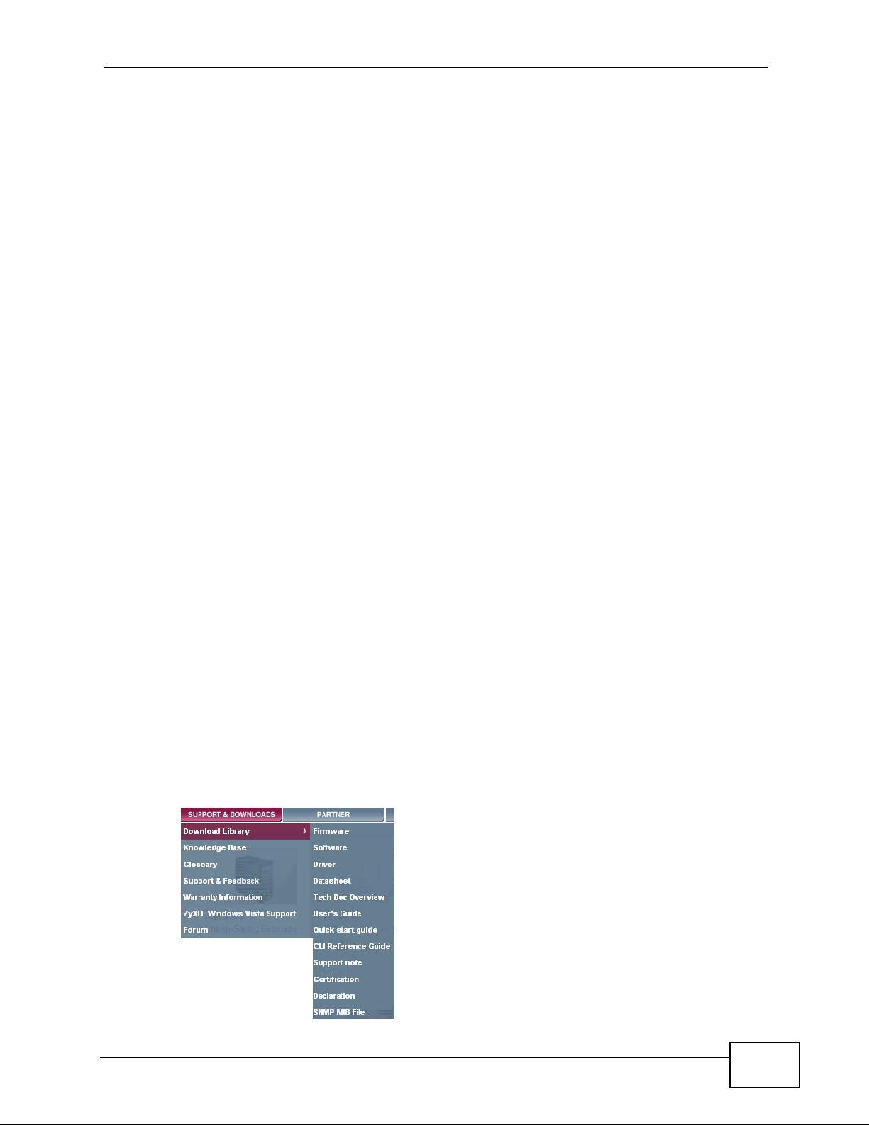
• Download Library
Search for the latest product updates and documentation from this link. Read
the Tech Doc Overview to find out how to efficiently use the User Guide, Quick
Start Guide and Command Line Interface Reference Guide in order to better
understand how to use your product.
• Knowledge Base
If you have a specific question about your product, the answer may be here.
This is a collection of answers to previously asked questions about ZyXEL
products.
•Forum
This contains discussions on ZyXEL prod ucts. Learn from others who use ZyXEL
products and share your experiences as well.
Customer Support
Should problems arise that cannot be solved by the methods listed above, you
should conta ct your vendor. If you cannot contact your vendor, then contact a
ZyXEL office for the region in which you bought the device.
See http://www.zyxel.com/web/contact_us.php for contact information. Please
have the following informatio n ready when you contact an office.
• Product model and serial number.
•Warranty Information.
• Date that you received your device.
• Brief description of the problem and the steps you took to solve it.
4
MES-3528 User’s Guide
Page 5

Document Conventions
Document Conventions
Warnings and Notes
These are how warnings and notes are shown in this User’s Guide.
Warnings tell you about things that could harm you or your device.
Note: Notes tell you other important information (for example, other things you may
need to configure or helpful tips) or recommendations.
Syntax Conventions
• The MES-3528 may be referred to as the “Switch”, the “device” , the “system” or
the “product” in this User’s Guide.
• Product labels, screen names, field labels and field choices are all in bold font.
• A key stroke is denoted by square brackets and uppercase text, for example,
[ENTER] means the “enter” or “ret urn” key on your keyboard.
• “Enter” means for you to type one or more characters and then press the
[ENTER] key. “Select” or “choose” means for you to use one of the predefined
choices.
• A right angle bracket ( > ) within a screen name denotes a mouse click. For
example, Maintenance > Log > Log Setting means you first click
Maintenance in the navigation panel, then the Log sub menu and finally the
Log Setting tab to get to that screen.
• Units of measurement may denote the “metric” value or the “scientific” value.
For example, “k” for kilo may denote “1000” or “1024”, “M” for mega may
denote “1000000” or “1048576” and so on.
• “e.g.,” is a shorthand for “for instance”, and “i.e.,” means “that is” or “in other
words”.
MES-3528 User’s Guide
5
Page 6
Document Conventions
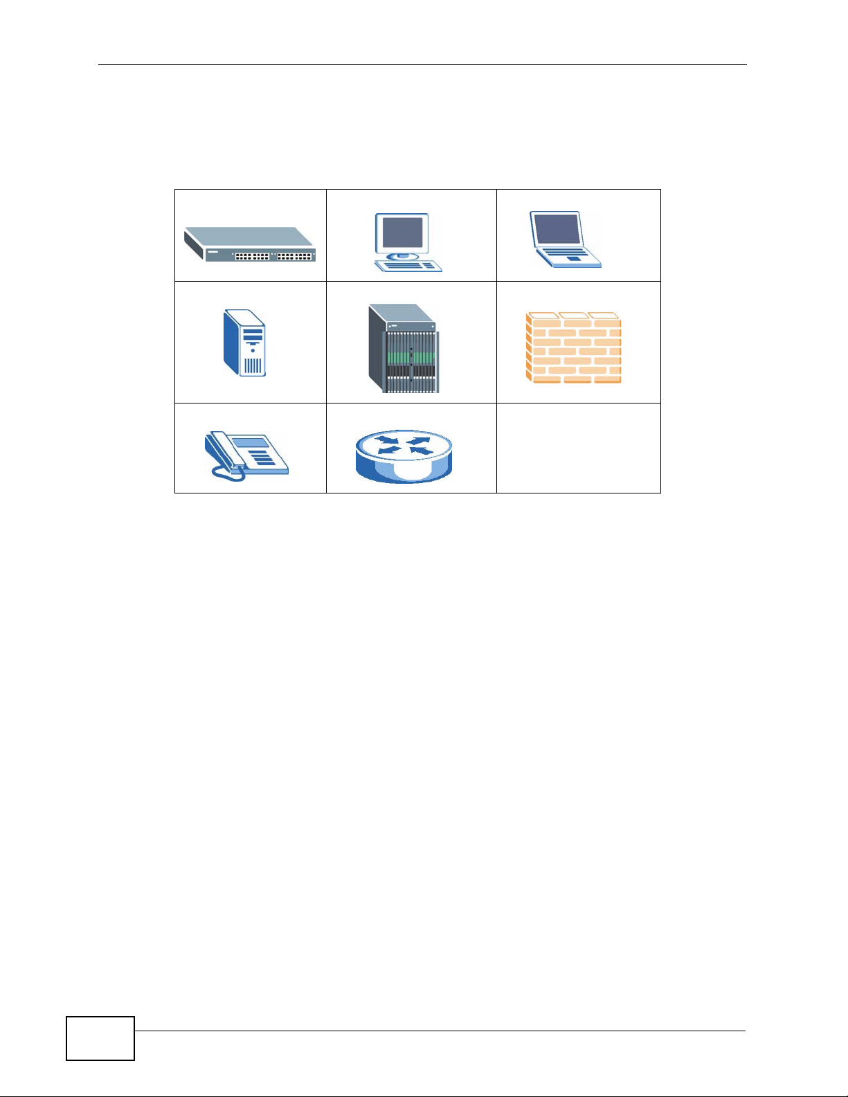
Icons Used in Figures
Figures in this User’s Guide may use the following generic icons. The S witch icon is
not an exact representation of your device.
The Switch Computer Notebook computer
Server DSLAM Firewall
Telephone Router
6
MES-3528 User’s Guide
Page 7

Safety Warnings
Safety Warnings
• Do NOT use this product near water, for example, in a wet basement or near a swimming
pool.
• Do NOT expose your device to dampness, dust or corrosive liquids.
• Do NOT store things on the device.
• Do NOT install, use, or service this device during a thunderstorm. There is a remote risk
of electric shock from lightning.
• Do not obstruct the device ventillation slots as insufficient airflow may harm your device.
• Connect ONLY suitable accessories to the device.
• Do NOT open the device or unit. Opening or removing covers can expose you to
dangerous high voltage points or other risks. ONLY qualified service personnel should
service or disassemble this device. Please contact your vendor for further information.
• Make sure to connect the cables to the correct ports.
• Place connecting cables carefully so that no one will step on them or stumble over them.
• Always disconnect all cables from this device before servicing or disassembling.
• Use ONLY an appropriate power adaptor or cord for your device. Connect it to the right
supply voltage (for example, 110V AC in North America or 230V AC in Europe).
• Use ONLY power wires of the appropriate wire gauge (see Chapter 41 on page 335 for
details) for your device. Connect it to a power supply of the correct voltage (see Chapter
41 on page 335 for details).
• Do NOT allow anything to rest on the power adaptor or cord and do NOT place the
product where anyone can walk on the power adaptor or cord.
• Do NOT use the device if the power adaptor or cord is damaged as it might cause
electrocution.
• If the power adaptor or cord is damaged, remove it from the device and the power
source.
• Do NOT attempt to repair the power adaptor or cord. Contact your local vendor to order a
new one.
• Fuse Warning! Replace a fuse only with a fuse of the same type and rating.
• The length of exposed (bare) power wire should not exceed 7 mm.
Your product is marked with this symbol, which is known as the WEEE mark.
WEEE stands for Waste Electronics and Electrical Equipment. It means that used
electrical and electronic products should not be mixed with general waste. Used
electrical and electronic equipment should be treated separately.
MES-3528 User’s Guide
7
Page 8

Safety Warnings
8
MES-3528 User’s Guide
Page 9

Contents Overview
Contents Overview
Introduction and Hardware ...................................................................................................21
Getting to Know Your Switch .....................................................................................................23
Hardware Installation and Connection ................................... ................................. ................... 29
Hardware Overview ................................................................................................................... 33
Basic Configuration ...............................................................................................................43
The Web Configurator ............................................................................................................... 45
Initial Setup Example ................................................................................................................. 55
Tutorials ..................................................................................................................................... 61
System Status and Port Statistics .................................... ..........................................................71
Basic Setting ............................................................................................................................. 77
Advanced ................................................................................................................................89
VLAN ......................................................................................................................................... 91
Static MAC Forward Setup .......................................................................................................111
Static Multicast Forward Setup .................................................................................................115
Filtering ..................................... .................................................... ............................................119
Spanning Tree Protocol ................... ... ... ... ... .... ........................................................................ 121
Bandwidth Control .... ... ... .... ... ... ... ............................................................................................ 143
Broadcast Storm Control ......................................................................................................... 147
Mirroring .................................................................................................................................. 149
Link Aggregation ................. .....................................................................................................151
Port Authentication ...... ... .... ... ..................................................................................................161
Port Security .................................... ... ... ... ............................................. .... ... ... ... .... ... ..............165
Classifier ................................... .................................................... ........................................... 169
Policy Rule .............................................................................................................................. 175
Queuing Method ...................................................................................................................... 181
VLAN Stacking ......................................................................................................................... 185
Multicast ..................................................................................................................................193
AAA ......................................................................................................................................... 209
IP Source Guard ...................................................................................................................... 223
Loop Guard ..................... .... ... ... ............................................. .... ... ... ... ... .... ... ... ... .... .................249
Layer 2 Protocol Tunneling .............. ... ... ... ... .... ... ... ... .... ... ... ... .................................................. 253
IP Application .......................................................................................................................257
Static Route ............................................................................................................................. 259
Differentiated Services ........................................ ... ... .... ... ... ... .... ... ........................................... 263
MES-3528 User’s Guide
9
Page 10

Contents Overview
DHCP ...................................................................................................................................... 267
Management .........................................................................................................................275
Maintenance ............................................................................................................................ 277
Access Control ........................................................................................................................ 285
Diagnostic .................................... ....................................................... ..................................... 307
Syslog ....................................... .................................................... ........................................... 309
Cluster Management .......... ... ................................................ .... ... ... ........................................ 313
MAC Table ............................................................................................................................... 321
ARP Table .............................. ... ... .... ... ... ... ............................................. .... ... ... ... .... ... ..............325
Configure Clone ....................................................................................................................... 327
Troubleshooting & Product Specifications .......................................................................329
Troubleshooting ..................................................... .................................................................. 331
Product Specifications ............................................................................................................. 335
Appendices and Index .........................................................................................................343
10
MES-3528 User’s Guide
Page 11

Table of Contents
Table of Contents
About This User's Guide..........................................................................................................3
Document Conventions............................................................................................................5
Safety Warnings ........................................................................................................................7
Contents Overview ...................................................................................................................9
Table of Contents....................................................................................................................11
Part I: Introduction and Hardware........................................................ 21
Chapter 1
Getting to Know Your Switch.................................................................................................23
1.1 Introduction ......................... ... .... ... ... ... ............................................. .... ... ... ... .... ... ... .............23
1.1.1 Backbone Application ............................................................. .... ... ... ... .... ... ................ 23
1.1.2 Bridging Example ......... .... ... ... ... ... .... ... ... ... .... ................................................ ... ... .... ... 24
1.1.3 High Performance Switching Example .......................................................................25
1.1.4 IEEE 802.1Q VLAN Application Examples ................................................................25
1.1.5 Metro Ethernet .................................................... ... .... ... .............................................26
1.2 Ways to Manage the Switch ............................ ... .............................................. ... ... ... ... .... ... 27
1.3 Good Habits for Managing the Switch ................................................................................. 28
Chapter 2
Hardware Installation and Connection .................................................................................29
2.1 Installation Scenarios ............................................. ... ... ... .... ... ... ... ... .... ... ... .......................... 29
2.2 Desktop Installation Procedure ...........................................................................................29
2.3 Mounting the Switch on a Rack .......................................................................................... 29
2.3.1 Rack-mounted Installation Requirements .................................................................. 30
2.3.2 Attaching the Mounting Brackets to the Switch ................................ .......................... 30
2.3.3 Mounting the Switch on a Rack .................................................................................. 31
Chapter 3
Hardware Overview.................................................................................................................33
3.1 Front Panel . .... ... ... ... .............................................. ... ... ... .... ... ... ... ....................................... 33
3.1.1 Console Port ....................................................... ... .... ... ... ... ... .... ... ............................. 34
3.1.2 Gigabit Ethernet Ports ........................................ ....................................................... 34
3.1.3 Mini-GBIC Slots ............................................................. ... ... ... .... ... ... ... .......................35
MES-3528 User’s Guide
11
Page 12

Table of Contents
3.1.4 Power Connector .......................................................... ... ... ....................................... 37
3.1.5 ALARM Slot .................. .... ... ... ... ... .... ............................................. ... ... .... ... ................ 37
3.2 LEDs ............................ ... ............................................. ... .... ... ............................................. 40
Part II: Basic Configuration................................................................... 43
Chapter 4
The Web Configurator............................................................................................................45
4.1 Introduction ......................... ... .... ... ... ... ............................................. .... ... ... ... .... ... ... .............45
4.2 System Login ....................................................................................................................45
4.3 The Status Screen .......................................................................................................... 46
4.3.1 Change Your Password .......................................................................................... 51
4.4 Saving Your Configuration ...................................................................................................51
4.5 Switch Lockout .............................................. ... .... ... ... ............................................. .......... 52
4.6 Resetting the Switch ............................... ... ... ... .............................................. ... ... ... ... ....... 52
4.6.1 Reload the Configuration File .................................................................................... 52
4.7 Logging Out of the Web Configurator ................................................................................. 53
4.8 Help ................................................... ... .... ... ... ............................................. .... ... ................54
Chapter 5
Initial Setup Example..............................................................................................................55
5.1 Overview ............. ............................................. ... .... ... ... ... .... ................................................ 55
5.1.1 Creating a VLAN ........................................................................................................ 55
5.1.2 Setting Port VID .................................................. ... .... ... ... ..........................................57
5.2 Configuring Switch Management IP Address ...................................................................... 58
Chapter 6
Tutorials...................................................................................................................................61
6.1 How to Use DHCP Snooping on the Switch ........................................................................ 61
6.2 How to Use DHCP Relay on the Switch .............................................................................. 65
6.2.1 DHCP Relay Tutorial Introduction .............................................................................. 65
6.2.2 Creating a VLAN ........................................................................................................ 66
6.2.3 Configuring DHCP Relay .............................................. ... ... ....................................... 69
6.2.4 Troubleshooting ............................................... ... ... .... ... ... ... ....................................... 69
Chapter 7
System Status and Port Statistics.........................................................................................71
7.1 Overview ............. ............................................. ... .... ... ... ... .... ................................................ 71
7.2 Port Status Summary ............................................................................................ ... ....... 72
7.2.1 Status: Port Details ................................................................................................73
12
MES-3528 User’s Guide
Page 13

Table of Contents
Chapter 8
Basic Setting ..........................................................................................................................77
8.1 Overview ............. ............................................. ... .... ... ... ... .... ................................................ 77
8.2 System Information ........................................................................................................... 77
8.3 General Setup ................................................................................................. ... ... .......... 78
8.4 Introduction to VLANs ........... .... ... ....................................................................................... 80
8.5 Switch Setup Screen .... ... ... .... ... ....................................................................................... 81
8.6 IP Setup .............................................................................................................................. 82
8.6.1 Management IP Addresses ........................................................................................ 83
8.7 Port Setup ................ .... ... ... ............................................. .... ... ... ... ... .... ................................ 85
Part III: Advanced................................................................................... 89
Chapter 9
VLAN........................................................................................................................................91
9.1 Introduction to IEEE 802.1Q Tagged VLANs .................................................................. 91
9.1.1 Forwarding Tagged and Untagged Frames ................................................................ 91
9.2 Automatic VLAN Registration ................................ ... ... ... .... ... ... ... ... .................................... 92
9.2.1 GARP . .... ... ... ... .... ... ... ............................................. .... ... ... .......................................... 92
9.2.2 GVRP . .... ... ... ... .... ... ... ............................................. .... ... ... .......................................... 92
9.3 Port VLAN Trunking ........... ............................................. .... ... ... ... ... .... ................................ 93
9.4 Select the VLAN Type .... ... ... .... ... ............................................. ... ... .... ... ... ... .... ... ... ... ..........94
9.5 Static VLAN . .... ... ... ... .............................................. ... ... ... .... ................................................ 94
9.5.1 VLAN Status ..............................................................................................................95
9.5.2 VLAN Details ............................................................................................................. 96
9.5.3 Configure a Static VLAN ........................................................................................ 97
9.5.4 Configure VLAN Port Settings ................................................................................ 99
9.6 Subnet Based VLANs .......................................................................................................100
9.7 Configuring Subnet Based VLAN ..... ................................................. ... ... ........................ 101
9.8 Protocol Based VLANs ...................................... .... ... ........................................................103
9.9 Configuring Protocol Based VLAN ............................................. ... .... ... ... ... .... ... ... ... ........104
9.10 Create an IP-based VLAN Example ................................................................................ 106
9.11 Port-based VLAN Setup .............................................................................................. 107
9.11.1 Configure a Port-based VLAN ............................................................................... 108
Chapter 10
Static MAC Forward Setup...................................................................................................111
10.1 Overview ...........................................................................................................................111
10.2 Configuring Static MAC Forwarding ............................................................................111
Chapter 11
Static Multicast Forward Setup............................................................................................115
MES-3528 User’s Guide
13
Page 14

Table of Contents
11.1 Static Multicast Forwarding Overview ...............................................................................115
11.2 Configuring Static Multicast Forwarding ............................................................................116
Chapter 12
Filtering..................................................................................................................................119
12.1 Configure a Filtering Rule ..............................................................................................119
Chapter 13
Spanning Tree Protocol........................................................................................................121
13.1 STP/RSTP Overview ...................................................................................................... 121
13.1.1 STP Terminology ................................................................................................... 121
13.1.2 How STP Works .................................................................................................... 122
13.1.3 STP Port States .....................................................................................................123
13.1.4 Multiple RSTP ....................................................................................................... 123
13.1.5 Multiple STP ........................................................................................................... 124
13.2 Spanning Tree Protocol Status Screen ............................................................................ 127
13.3 Spanning Tree Configuration ..........................................................................................128
13.4 Configure Rapid Spanning Tree Protocol ..................................................................... 129
13.5 Rapid Spanning Tree Protocol Status ........................................................................ 131
13.6 Configure Multiple Rapid Spanning Tree Protocol ........................................................ 133
13.7 Multiple Rapid Spanning Tree Protocol Status .......................................................... 135
13.8 Configure Multiple Spanning Tree Protocol .................................................................. 137
13.9 Multiple Spanning Tree Protocol Status .....................................................................140
Chapter 14
Bandwidth Control................................................................................................................143
14.1 Bandwidth Control Overview .......................................................................................... 143
14.2 Bandwidth Control Setup ................................................................................................. 144
Chapter 15
Broadcast Storm Control.....................................................................................................147
15.1 Broadcast Storm Control Setup ...................................................................................... 147
Chapter 16
Mirroring................................................................................................................................149
16.1 Port Mirroring Setup ....................................................................................................... 149
Chapter 17
Link Aggregation ..................................................................................................................151
17.1 Link Aggregation Overview ........................ ....................... ...................... ....................... . 151
17.2 Dynamic Link Aggregation ..............................................................................................151
17.2.1 Link Aggregation ID ............................................................................................... 152
17.3 Link Aggregation Status ....................................................... .......................... .................153
14
MES-3528 User’s Guide
Page 15

Table of Contents
17.4 Link Aggregation Setting ................................................................................................ 155
17.5 Link Aggregation Control Protocol ................................................................................ 157
17.6 Static Trunking Example ..................................................................................................158
Chapter 18
Port Authentication...............................................................................................................161
18.1 Port Authentication Overview ......................................................................................... 161
18.1.1 IEEE 802.1x Authentication ................................................................................... 161
18.2 Port Authentication Configuration ............................ ....................................................... .162
18.2.1 Activate IEEE 802.1x Security ........................................................................... 163
Chapter 19
Port Security..........................................................................................................................165
19.1 About Port Security .........................................................................................................165
19.2 Port Security Setup .............................. ....................... ....................... ................... ........... 166
Chapter 20
Classifier................................................................................................................................169
20.1 About the Classifier and QoS .......................................................................................... 169
20.2 Configuring the Classifier ...............................................................................................169
20.3 Viewing and Editing Classifier Configuration ................................. .................................. 172
20.4 Classifier Example ...........................................................................................................173
Chapter 21
Policy Rule............................................................................................................................175
21.1 Policy Rules Overview ....................................................................................................175
21.2 Configuring Policy Rules ................................................................................................. 175
21.3 Viewing and Editing Policy Configuration ........................................................................ 178
21.4 Policy Example ................................................................................................................ 179
Chapter 22
Queuing Method....................................................................................................................181
22.1 Queuing Method Overview ............................................................................................. 181
22.1.1 Strictly Priority Queuing .......................................................................................... 181
22.1.2 Weighted Fair Queuing .......................................................................................... 181
22.1.3 Weighted Round Robin Scheduling (WRR) ........................................................... 182
22.2 Configuring Queuing ........................................................................................................ 183
Chapter 23
VLAN Stacking......................................................................................................................185
23.1 VLAN Stacking Overview ................................................................................................ 185
23.1.1 VLAN Stacking Example ........................................................................................ 185
23.2 VLAN Stacking Port Roles ................ ... .... ........................................................................ 186
MES-3528 User’s Guide
15
Page 16

Table of Contents
23.3 VLAN Tag Format .......... ..................................................................................................187
23.3.1 Frame Format ........................................................................................................187
23.4 Configuring VLAN Stacking ............................................................................................. 189
23.4.1 Configuring SVLAN ................................................................................................190
Chapter 24
Multicast ................................................................................................................................193
24.1 Multicast Overview ......................................................................................................... 193
24.1.1 IP Multicast Addresses ........................................................................................... 193
24.1.2 IGMP Filtering ........................................................................................................ 193
24.1.3 IGMP Snooping ..................................................................................................... 194
24.1.4 IGMP Snooping and VLANs ................................................................................... 194
24.2 Multicast Status .............................................................................................................. 194
24.3 Multicast Setting .............. ... .... ... ................................................ ... .... .............................. 195
24.4 IGMP Snooping VLAN .................................................................................................... 198
24.5 IGMP Filtering Profile ..................................................................................................... 199
24.6 MVR Overview ................................................................................................................ 201
24.6.1 Types of MVR Ports ............................................................................................... 201
24.6.2 MVR Modes ........................................................................................................... 202
24.6.3 How MVR Works .................................................................................................... 202
24.7 General MVR Configuration ............................................................................................ 203
24.8 MVR Group Configuration ..............................................................................................205
24.8.1 MVR Configuration Example ... ... .... ... ..................................................................... 206
Chapter 25
AAA........................................................................................................................................209
25.1 Authentication, Authorization and Accounting (AAA) ..................................................... 209
25.1.1 Local User Accounts .................. .... ... ... ... .... ... ................................................ ... .... . 210
25.1.2 RADIUS and TACACS+ ........................................................................................ 210
25.2 AAA Screens ................................................................................................................... 210
25.2.1 RADIUS Server Setup .........................................................................................211
25.2.2 TACACS+ Server Setup ..................................................................................... 213
25.2.3 AAA Setup ............................................................................................................. 215
25.2.4 Vendor Specific Attribute ........................................................................................ 218
25.3 Supported RADIUS Attributes ......................................................................................... 219
25.3.1 Attributes Used for Authentication ............................ ............ .......... .......... ......... ..... 220
25.3.2 Attributes Used for Accounting ............................................................................... 221
Chapter 26
IP Source Guard ....................................................................................................................223
26.1 IP Source Guard Overview .............................................................................................. 223
26.1.1 DHCP Snooping Overview ..................................................................................... 224
26.1.2 ARP Inspection Overview ...................................................................................... 226
16
MES-3528 User’s Guide
Page 17

Table of Contents
26.2 IP Source Guard .............................................................................................................. 227
26.3 IP Source Guard Static Binding ....................................................................................... 228
26.4 DHCP Snooping .............................................................................................................. 230
26.5 DHCP Snooping Configure ...................... ........................................................................ 234
26.5.1 DHCP Snooping Port Configure ............................................................................. 236
26.5.2 DHCP Snooping VLAN Configure .......................................................................... 237
26.6 ARP Inspection Status .....................................................................................................239
26.6.1 ARP Inspection VLAN Status .................................................................................240
26.6.2 ARP Inspection Log Status .................................................................................... 241
26.7 ARP Inspection Configure ............................................................................................... 242
26.7.1 ARP Inspection Port Configure .............................................................................. 244
26.7.2 ARP Inspection VLAN Configure ........................................................................... 246
Chapter 27
Loop Guard............................................................................................................................249
27.1 Loop Guard Overview .....................................................................................................249
27.2 Loop Guard Setup ...........................................................................................................251
Chapter 28
Layer 2 Protocol Tunneling..................................................................................................253
28.1 Layer 2 Protocol Tunneling Overview ............................................................................. 253
28.1.1 Layer 2 Protocol Tunneling Mode .......................................................................... 254
28.2 Configuring Layer 2 Protocol Tunneling .................................................................. ... .... . 255
Part IV: IP Application.......................................................................... 257
Chapter 29
Static Route...........................................................................................................................259
29.1 Static Routing Overview .................................................................................................. 259
29.2 Configuring Static Routing ............................................................................................... 260
Chapter 30
Differentiated Services.........................................................................................................263
30.1 DiffServ Overview ...........................................................................................................263
30.1.1 DSCP and Per-Hop Behavior ................................................................................ 263
30.1.2 DiffServ Network Example .................................................................................... 264
30.2 Activating DiffServ .......................................................................................................... 264
30.3 DSCP-to-IEEE 802.1p Priority Settings ......................................................................... 265
30.3.1 Configuring DSCP Settings ............................ .......................................... .............. 266
Chapter 31
DHCP......................................................................................................................................267
MES-3528 User’s Guide
17
Page 18

Table of Contents
31.1 DHCP Overview ............................................................................................................. 267
31.1.1 DHCP Modes ........................................................................................................267
31.1.2 DHCP Configuration Options ................................................................................. 267
31.2 DHCP Status ................................................................................................................... 268
31.3 DHCP Relay ....... ... .... ... ... ... .... ... ... ... ... ............................................................................ 268
31.3.1 DHCP Relay Agent Information ............................................................................. 268
31.3.2 Configuring DHCP Global Relay ............................................................................ 269
31.3.3 Global DHCP Relay Configuration Example .......................................................... 270
31.4 Configuring DHCP VLAN Settings ................................................................................ 271
31.4.1 Example: DHCP Relay for Two VLANs .................................................................. 273
Part V: Management............................................................................. 275
Chapter 32
Maintenance..........................................................................................................................277
32.1 The Maintenance Screen ...................................... ... ... .... ... ... ........................................ 277
32.2 Load Factory Default ...................................................................................................... 278
32.3 Save Configuration .......................................................................................................... 279
32.4 Reboot System ................................................................................................................ 279
32.5 Firmware Upgrade ........................................................................................................ 279
32.6 Restore a Configuration File .........................................................................................280
32.7 Backup a Configuration File ......................................................................................... 281
32.8 FTP Command Line ........................................................................................................ 281
32.8.1 Filename Conventions .......................................................................................... 281
32.8.2 FTP Command Line Procedure ............................................................................ 282
32.8.3 GUI-based FTP Clients .......................................................................................... 283
32.8.4 FTP Restrictions .................................................................................................... 283
Chapter 33
Access Control......................................................................................................................285
33.1 Access Control Overview ............................................................................................ 285
33.2 The Access Control Main Screen .................................................................................... 285
33.3 About SNMP .................................................................................................................. 286
33.3.1 SNMP v3 and Security ........................................................................................... 287
33.3.2 Supported MIBs .................................................................................................... 287
33.3.3 SNMP Traps .......................................................................................................... 288
33.3.4 Configuring SNMP ................................................................................................292
33.3.5 Configuring SNMP Trap Group ...........................................................................294
33.3.6 Setting Up Login Accounts .................................................................................295
33.4 SSH Overview ................................................................................................................. 297
33.5 How SSH works ................ ... ............................................................................................ 298
18
MES-3528 User’s Guide
Page 19

Table of Contents
33.6 SSH Implementation on the Switch ................................................................................. 299
33.6.1 Requirements for Using SSH .................................................................................299
33.7 Introduction to HTTPS .....................................................................................................299
33.8 HTTPS Example .............................................................................................................. 300
33.8.1 Internet Explorer Warning Messages ..................................................................... 300
33.8.2 Netscape Navigator Warning Messages ................................................................ 301
33.8.3 The Main Screen .................................................................................................... 303
33.9 Service Port Access Control ......................................................................................... 303
33.10 Remote Management ............................................................................................... 304
Chapter 34
Diagnostic..............................................................................................................................307
34.1 Diagnostic ....................................................................................................................... 307
Chapter 35
Syslog....................................................................................................................................309
35.1 Syslog Overview .............................................................................................................. 309
35.2 Syslog Setup .................................................................................................................. 310
35.3 Syslog Server Setup ........................................................................................................311
Chapter 36
Cluster Management.............................................................................................................313
36.1 Cluster Management Status Overview ........................................................................... 313
36.2 Cluster Management Status ........................................................................................... 314
36.2.1 Cluster Member Switch Management ................................................................... 315
36.3 Clustering Management Configuration .......................................................................... 318
Chapter 37
MAC Table..............................................................................................................................321
37.1 MAC Table Overview ...................................................................................................... 321
37.2 Viewing the MAC Table ...................................................................................................322
Chapter 38
ARP Table..............................................................................................................................325
38.1 ARP Table Overview .......................................................................................................325
38.1.1 How ARP Works ......................................................... ... ... ... .... ... ... ........................ 325
38.2 Viewing the ARP Table ................................................................................................... 326
Chapter 39
Configure Clone....................................................................................................................327
39.1 Configure Clone ..............................................................................................................327
MES-3528 User’s Guide
19
Page 20

Table of Contents
Part VI: Troubleshooting & Product Specifications.......................... 329
Chapter 40
Troubleshooting....................................................................................................................331
40.1 Power, Hardware Connections, and LEDs .............................. ... ... .... ... ... ... .... ... ... ... ........331
40.2 Switch Access and Login .................................................................................................332
40.3 Switch Configuration ........................................................................................................334
Chapter 41
Product Specifications.........................................................................................................335
Part VII: Appendices and Index.......................................................... 343
Appendix A Changing a Fuse ..............................................................................................345
Appendix B Common Services.............................................................................................347
Appendix C Legal Information..............................................................................................351
Index.......................................................................................................................................355
20
MES-3528 User’s Guide
Page 21

PART I
Introduction and
Hardware
Getting to Know Your Switch (23)
Hardware Installation and Connection
(29)
Hardware Overview (33)
21
Page 22

22
Page 23

CHAPTER 1
Getting to Know Your Switch
This chapter introduces the main features and applications of the Switch.
1.1 Introduction
The Switch is a layer-2 standalone Ethernet switch with additional layer-2, layer -3,
and layer-4 features suitable for metro ethernets. The Switch has twenty-four 10/
100 Mbps Ethernet ports. It also has four GbE dual personality interfaces with
each interface comprising one mini-GBIC slot and one 100/1000 Mbps RJ-45 port,
with either port or slot active at a time.
With its built-in web configurat or, managing and configuring the Switch is easy. In
addition, the Switch can also be managed via Telnet, any terminal emulator
program on the console port, or third-party SNMP management.
See Chapter 41 on page 335 for a full list of software features available on the
Switch.
This section shows a few examples of using the Switch in various network
environments.
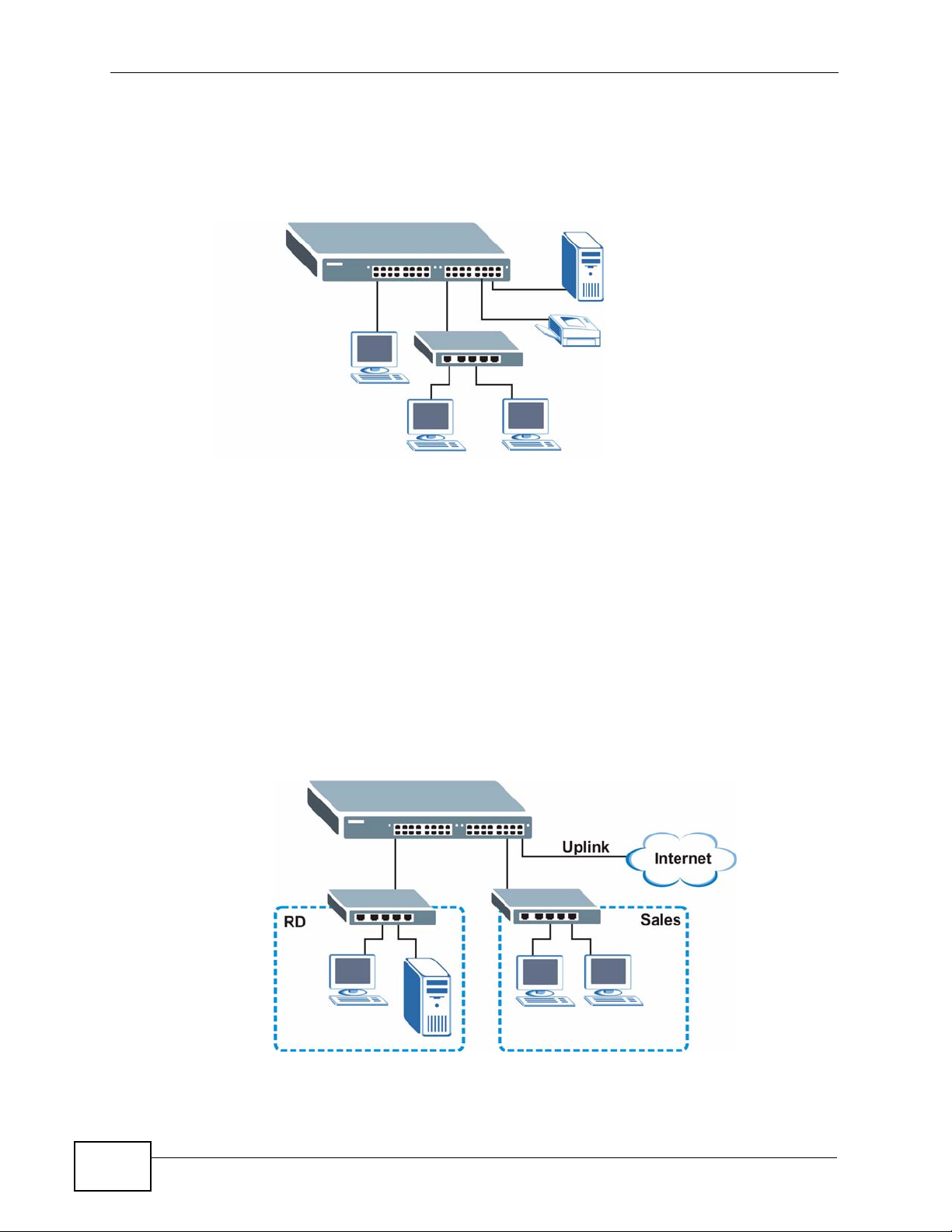
1.1.1 Backbone Application
The Switch is an ideal solution for small networks where rapid growth can be
expected in the near future. The Switch can be used standalone for a group of
heavy traffic users. You can connect computers and servers directly to the
Switch’s port or connect other switches to the Switch.
MES-3528 User’s Guide
23
Page 24
Chapter 1 Getting to Know Your Switch
In this example, all computers can share high-speed applications on the server. T o
expand the network, simply add more networking devices such as switches,
routers, computers, print servers etc.
Figure 1 Backbone Application
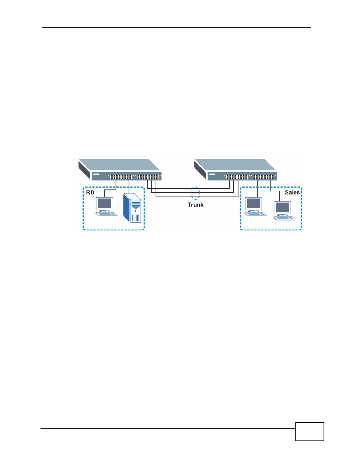
1.1.2 Bridging Example
In this example, the Switch connects different company departments (RD and
Sales) to the corporate backbone. It can alleviate bandwidth contention and
eliminate server and network bottlenecks. All users that need high bandwidth can
connect to high-speed department servers via the Switch. You can provide a
super-fast uplink connection by using a Gigabit Ethernet/mini-GBIC port on the
Switch.
Moreover, the Switch eases supervision and maintenance by allowing network
managers to centralize multiple servers at a single location.
Figure 2 Bridging Application
24
MES-3528 User’s Guide
Page 25
Chapter 1 Getting to Know Your Switch
1.1.3 High Performance Switching Example
The Switch is ideal for connecting two networks that need high bandwidth. In the
following example, use trunking to connect these two networks.
Switching to higher-speed LANs such as ATM (Asynchronous Tr ansmission Mode)
is not feasible for most people due to the expense of replacing all existing
Ethernet cables and adapter cards, restructuring your network and complex
maintenance. The Switch can provide the same bandwidth as ATM at much lower
cost while still being able to use existing adapters and switches. Moreover, the
current LAN structure can be retained as all ports can freely communicate with
each other.
Figure 3 High Performance Switched Workgroup Application
1.1.4 IEEE 802.1Q VLAN Application Examples
A VLAN (Virtual Local Area Network) allows a physical network to be partitioned
into multiple logical networks. Stations on a logical network belong to one group.
A station can belong to more than one group. With VLAN, a station cannot directly
talk to or hear from stations that are not in the same group(s) unless such traffic
first goes through a router.
For more information on VLANs, refer to Chapter 9 on page 91.
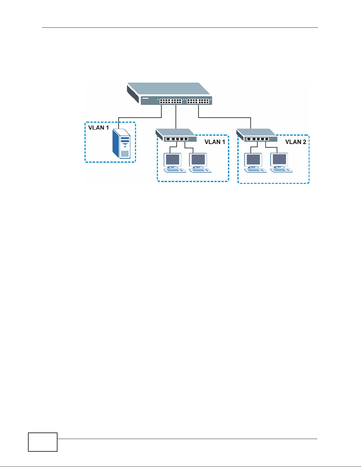
1.1.4.1 Tag-based VLAN Example
Ports in the same VLAN group share the same frame broadcast domain thus
increase network performance through reduced broadcast traffic. VLAN groups
can be modified at any time by adding, moving or changing ports without any recabling.
MES-3528 User’s Guide
25
Page 26
Chapter 1 Getting to Know Your Switch
Shared resources such as a server can be used by all ports in the same VLAN as
the server. In the following figure only ports that need access to the server need
to be part of VLAN 1. Ports can belong to other VLAN groups too.
Figure 4 Shared Server Using VLAN Example
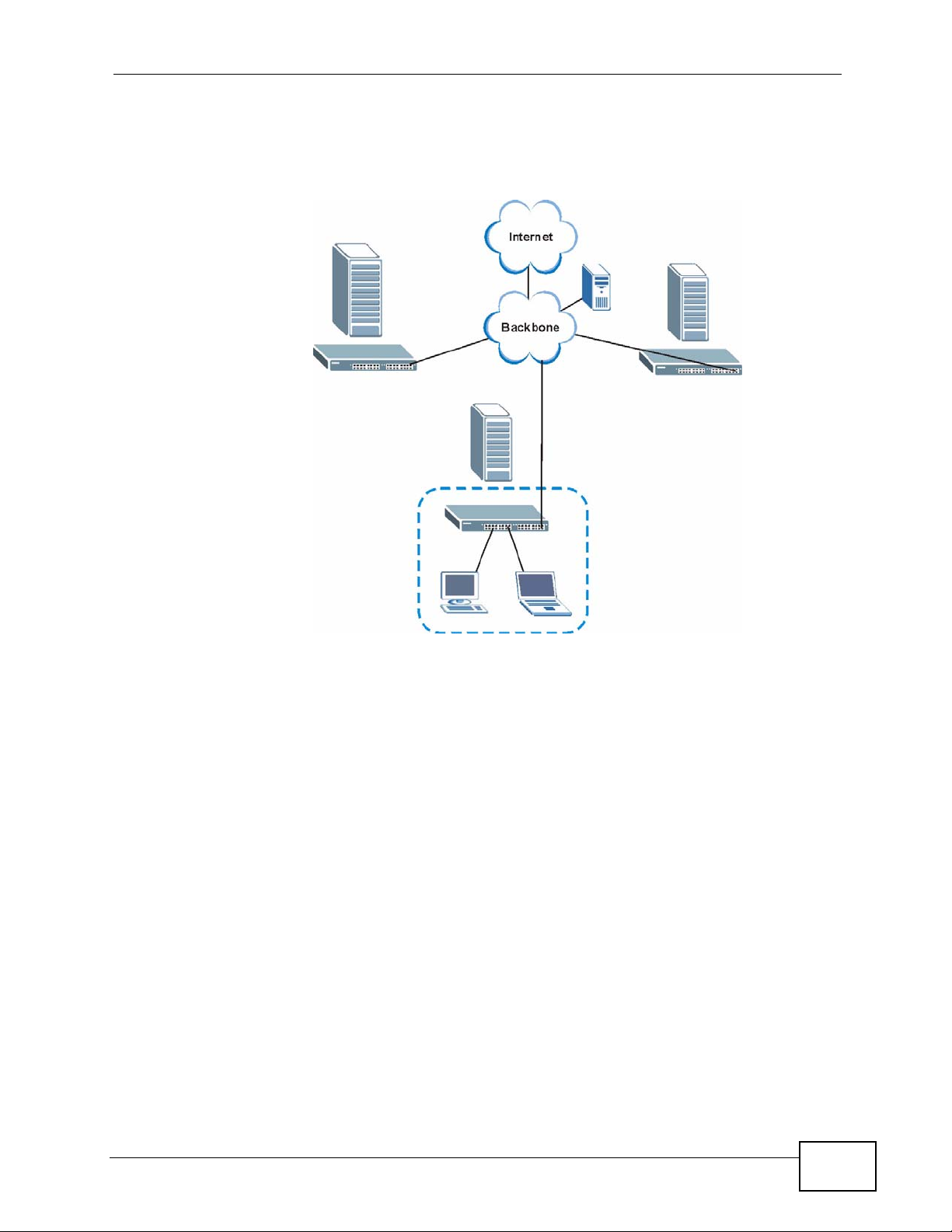
1.1.5 Metro Ethernet
The Switch is ideal for connecting users to an Ethernet network that spans a
metropolitan area.
In the following example, the Switch is one of many switches that connect users in
the metropolitan area to the Internet. The metro ethernet is based on a star (or
hub-and-spoke) topology, though other topologies, such as ring or mesh, are also
26
MES-3528 User’s Guide
Page 27
Chapter 1 Getting to Know Your Switch
possible. The Switch is connected to the backbone and the metropolitan servers
over an optical network that provides higher bandwidth than copper.
Figure 5 Metro Ethernet
1.2 Ways to Manage the Switch
Use any of the following methods to manage the Switch.
• Web Conf igurator. This is recommended for ev eryday management of the Sw itch
using a (supported) web browser. See Chapter 4 on page 45.
• Command Line Interface. Line commands offer an alternative to the web
configurator and in some cases are necessary to configure advanced features.
See the CLI Reference Guide.
• FTP. Use FTP for firmware upgrades and configuration backup/restore. See
Section 32.8 on page 281.
• SNMP. The Switch can be monitored by an SNMP manager. See Section 33.3 on
page 286.
• Cluster Management. Cluster Management allows you to manage multiple
switches through one switch, called the cluster manager. See Chapter 36 on
page 313.
MES-3528 User’s Guide
27
Page 28

Chapter 1 Getting to Know Your Switch
1.3 Good Habits for Managing the Switch
Do the following things regularly to make the Switch more secure and to manage
the Switch more effectively.
• Change the password. Use a password that’s not easy to guess and that consists
of different types of characters, such as numbers and letters.
• Write down the password and put it in a safe place.
• Back up the configuration (and make sure you know how to restore it).
Restoring an earlier working configuration may be useful if the device becomes
unstable or even crashes. If you forget y our password, you will hav e to reset the
Switch to its factory default settings. If you backed up an earlier configuration
file, you would not have to totally re-configure the Switch. You could simply
restore your last configuration.
28
MES-3528 User’s Guide
Page 29

CHAPTER 2
Hardware Installation and
Connection
This chapter shows you how to install and connect the Switch.
2.1 Installation Scenarios
The Switch can be placed on a desktop or rack-mounted on a standard EIA rack.
Use the rubber feet in a desktop installation and the brackets in a rack-mounted
installation.
Note: For proper ventilation, allow at least 4 inches (10 cm) of clearance at the front
and 3.4 inches (8 cm) at the back of the Switch. This is especially important for
enclosed rack installations.
2.2 Desktop Installation Procedure
1 Make sure the Switch is clean and dry.
2 Set the Switch on a smooth, level surface strong enough to support the weight of
the Switch and the connected cables. Make sure there is a power outlet nearby.
3 Make sure there is enough clearance around the Switch to allow air circulation and
the attachment of cables and the power cord.
2.3 Mounting the Switch on a Rack
The Switch can be mounted on an EIA standard size, 19-inch rack or in a wiring
closet with other equipment. Follow the steps below to mount your Switch on a
standard EIA rack using a rack-mounting kit.
MES-3528 User’s Guide
29
Page 30
Chapter 2 Hardware Installation and Connection
2.3.1 Rack-mounted Installation Requirements
• Two mounting brackets.
• Eight M3 flat head screws and a #2 Philips screwdriver.
• Four M5 flat head screws and a #2 Philips screwdriver.
Failure to use the proper screws may damage the unit.
2.3.1.1 Precautions
• Make sure the rack will safely support the combined weight of all the equipment
it contains.
• Make sure the position of the Switch does not make the rack unstable or topheavy. Tak e all necessary precautions to anchor the rack securely before
installing the unit.
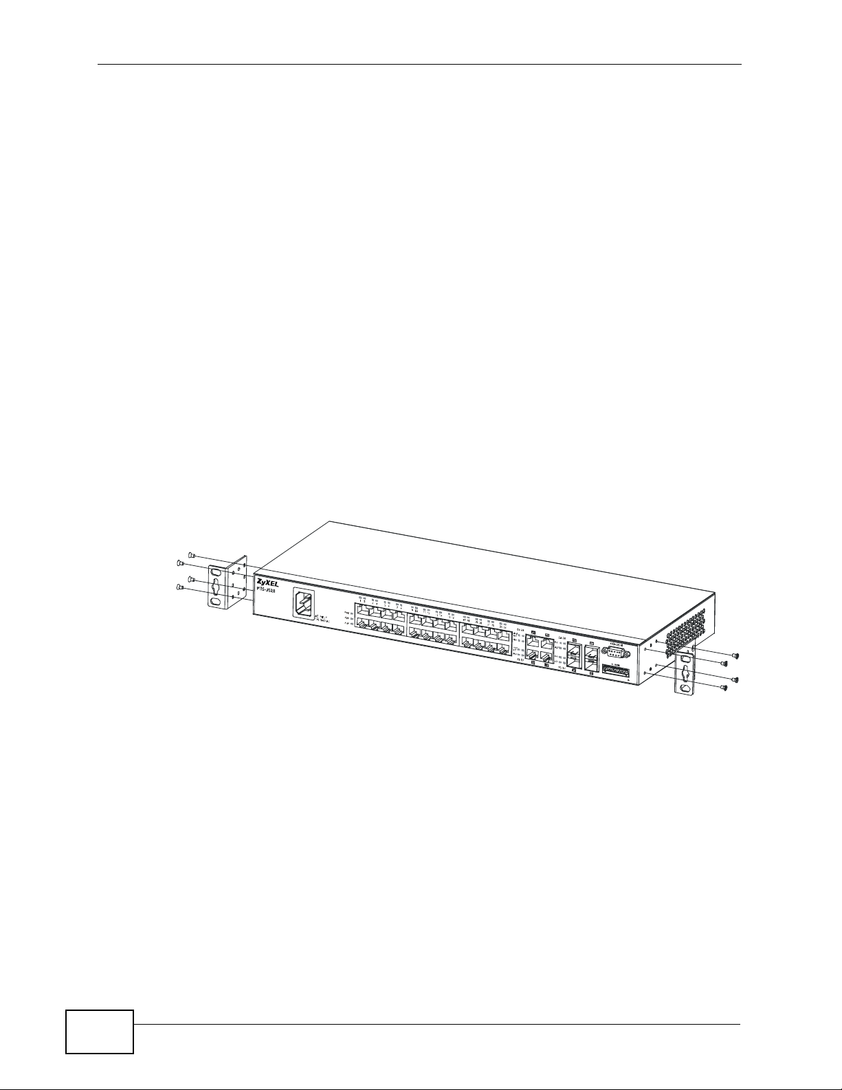
2.3.2 Attaching the Mounting Brackets to the Switch
1 Position a mounting bracket on one side of the Switch, lining up the four screw
holes on the bracket with the screw holes on the side of the Switch.
Figure 6 Attaching the Mounting Brackets
2 Using a #2 Philips screwdriver, install the M3 flat head screws through the
mounting bracket holes into the Switch.
3 Repeat steps 1 and 2 to install the second mounting bracket on the other side of
the Switch.
4 You may now mount the Switch on a rack. Proceed to the next section.
30
MES-3528 User’s Guide
Page 31

Chapter 2 Hardware Installation and Conn ec t ion
2.3.3 Mounting the Switch on a Rack
1 Position a mounting br acket (that is already attached to the Switch) on one s ide of
the rack, lining up the two screw holes on the br ack et with the screw holes on the
side of the rack.
Figure 7 Mounting the Switch on a Rack
2 Using a #2 Philips screwdriver, install the M5 flat head screws through the
mounting bracket holes into the rack.
3 Repeat steps 1 and 2 to attach the second mounting bracket on the other side of
the rack.
MES-3528 User’s Guide
31
Page 32

Chapter 2 Hardware Installation and Connection
32
MES-3528 User’s Guide
Page 33

CHAPTER 3
Hardware Overview
This chapter describes the front panel and rear panel of the Switch and shows y ou
how to make the hardware connections.
3.1 Front Panel
The following figure shows the front panel of the Switch.
Figure 8 Front Panel
LEDs
Console Port
Power Connection
The following table describes the port labels on the front panel.
Table 1 Front Panel Connections
LABEL DESCRIPTION
Power
Connection
24 10/100
Mbps RJ-45
Ethernet
Ports
Connect an appropriate power supply to this port.
Connect these ports to a computer, a hub, an Ethernet switch or router.
Ethernet Ports
Dual Personality Interfaces
ALARM slot
MES-3528 User’s Guide
33
Page 34

Chapter 3 Hardware Overview
Table 1 Front Panel Connections (continued)
LABEL DESCRIPTION
Four Dual
Personality
Interfaces
Console Port The console port is for local configuration of the Switch.
Alarm Connect the alarm input pins to alarm output terminals on other pieces of
Each interface has one 1000BASE-T RJ-45 port and one Small Form-F actor
Pluggable (SFP) slot (also called a mini-GBIC slot), with one port or
transceiver active at a time.
• Four 100/1000 Mbps RJ-45 Ports:
Connect these ports to high-bandwidth backbone network Ethernet
switches using 1000BASE-T compatible Category 5/5e/6 copper cables.
•Four Mini-GBIC Slots:
Use mini-GBIC transceivers in these slots for connections to backbone
Ethernet switches.
equipment.
Connect the alarm output pins to an alarm input terminal on another piece
of equipment.
See Chapter 41 on page 335 for details on the pin assignments required.
3.1.1 Console Port
For local management, you can use a computer with terminal emulation software
configured to the following parameters:
• VT100
• Terminal emulation
• 9600 bps
• No parity, 8 data bits, 1 stop bit
• No flow control
Connect the male 9-pin end of the console cable to the console port of the Switch.
Connect the female end to a serial port (COM1, COM2 or other COM port) of your
computer.
3.1.2 Gigabit Ethernet Ports
The Switch has 1000Base-T auto-negotiating, auto-crossover Ethernet ports. In
10/100/1000 Mbps Fast Ethernet, the speed can be 10 Mbps, 100 Mbps or 1000
Mbps and the duplex mode can be half duplex or full duplex.
34
An auto-negotiating port can detect and adjust to the optimum Ethernet speed
(10/100/1000 Mbps) and duplex mode (full duplex or half duplex) of the
connected device.
MES-3528 User’s Guide
Page 35

An auto-crossover (auto-MDI/MDI-X) port automatically works with a straightthrough or crossover Ethernet cable.
Four 1000Base-T Ethernet ports are paired with a mini-GBIC slot to create a dual
personality interface. The Switch uses up to one connection for each mini-GBIC
and 1000Base-T Ethernet pair. The mini-GBIC slots have priority over the Gigabit
ports. This means that if a mini-GBIC slot and the corresponding GbE port are
connected at the same time, the GbE port will be disabled.
When auto-negotiation is turned on, an Ethernet port negotiates with the peer
automatically to determine the connection speed and duplex mode. If the peer
Ethernet port does not support auto-negotiation or turns off this feature, the
Switch determines the connection speed by detecting the signal on the cable and
using half duplex mode. When the Switch’s auto-negotiation is turned off, an
Ethernet port uses the pre-configured speed and duplex mode when making a
connection, thus requiring you to make sure that the settings of the peer Ethernet
port are the same in order to connect.
3.1.2.1 Default Ethernet Negotiation Settings
Chapter 3 Hardware Overview
The factory default negotiation settings for the Gigabit ports on the Switch are:
• Speed: Auto
•Duplex: Auto
• Flow control: Off
•Link Aggregation: Disabled
3.1.2.2 Auto-crossover
All ports are auto-crossover, that is auto-MDIX ports (Media Dependent Interface
Crossover), so you may use either a straight-through Ethernet cable or crossover
Ethernet cable for all Gigabit port connections. Auto-crossover ports automatically
sense whether they need to function as crossover or straight ports, so crossover
cables can connect both computers and switches/hubs.
3.1.3 Mini-GBIC Slots
These are slots for mini-GBIC (Gigabit Interface Converter) transceivers. A
transceiver is a single unit that houses a transmitter and a receiver. The Switch
does not come with transceivers. You must use transceivers that comply with the
Small Form-factor Pluggable (SFP) Transceiver MultiSource Agreement (MSA). See
the SFF committee’s INF-8074i specification Rev 1.0 for details.
You can change transceivers while the Switch is operating. You can use different
transceivers to connect to Ethernet switches with different t ypes of fiber-optic or
even copper cable connectors.
MES-3528 User’s Guide
35
Page 36

Chapter 3 Hardware Overview
To avoid possible eye injury, do not look into an operating fiberoptic module’s connectors.
• Type: SFP connection interface
• Connection speed: 1 Gigabit per second (Gbps)
3.1.3.1 Transceiver Installation
Use the following steps to install a mini-GBIC transceiver (SFP module).
1 Insert the transceiver into the slot with the exposed section of PCB board facing
down.
2 Press the transceiver firmly until it clicks into place.
3 The Switch automatically detects the installed transceiver. Check the LEDs to
verify that it is functioning properly.
4 Close the transceiver’s latch (latch styles vary).
5 Connect the fiber optic cables to the transceiver.
Figure 9 Transceiver Installation Example
Figure 10 Connecting the Fiber Optic Cables
3.1.3.2 Transceiver Removal
Use the following steps to remove a mini-GBIC transceiver (SFP module).
1 Remove the fiber optic cables from the transceiver.
36
2 Open the transceiver’s latch (latch styles vary).
MES-3528 User’s Guide
Page 37
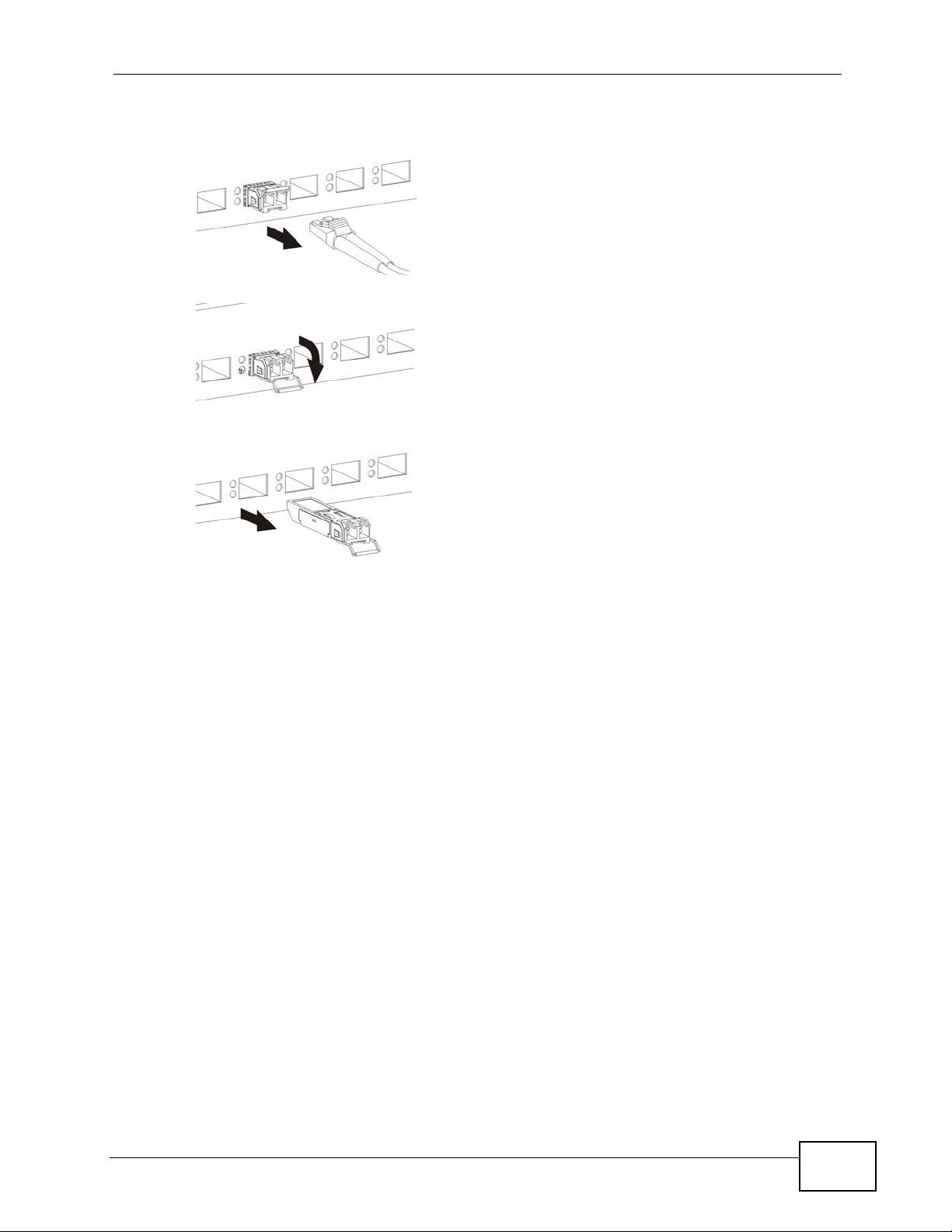
3 Pull the transceiver out of the slot.
Figure 11 Removing the Fiber Optic Cables
Figure 12 Opening the Transceiver’s Latch Example
Figure 13 Transceiver Removal Example
Chapter 3 Hardware Overview
3.1.4 Power Connector
Note: Make sure you are using the correct power source as shown on the panel.
To connect power to the Switch, insert the female end of the power cord to the AC
power receptacle on the front panel. Connect the other end of the supplied power
cord to a power outlet. Make sure that no objects obstruct the airfl ow of the fans
(located on the side of the unit).
See Chapter 41 on page 335 for information on the Switch’s power supply
requirements.
3.1.5 ALARM Slot
The ALARM slot ( fitted with the alarm connector) allows you to connect devices to
the Switch, such as smoke or movement detectors, sensors, or even other ZyXEL
switches which support the external alarm feature. This feature is in addition to
the system alarm, which detects abnormal temperatures, voltage levels and fan
speeds on the Switch.
Your Switch can respond to an external alarm in five ways.
•The ALM LED shows an alert.
MES-3528 User’s Guide
37
Page 38
Chapter 3 Hardware Overview
•The ALARM slot can send an external alarm on to another device such as an
alarm bell.
• By daisy-chaining the alarm sensor cables from one Switch to another ZyXEL
switch which supports this feature, the external alarm alert (but not the system
alarm) is received on each Switch.
• The Switch can be configured to send an SNMP trap to the SNMP server. See
Section 33.3 on page 286 for more information on using SNMP.
• The Switch can be configured to create an error log of the alarm. See Section
35.1 on page 309 for more information on using the system log.
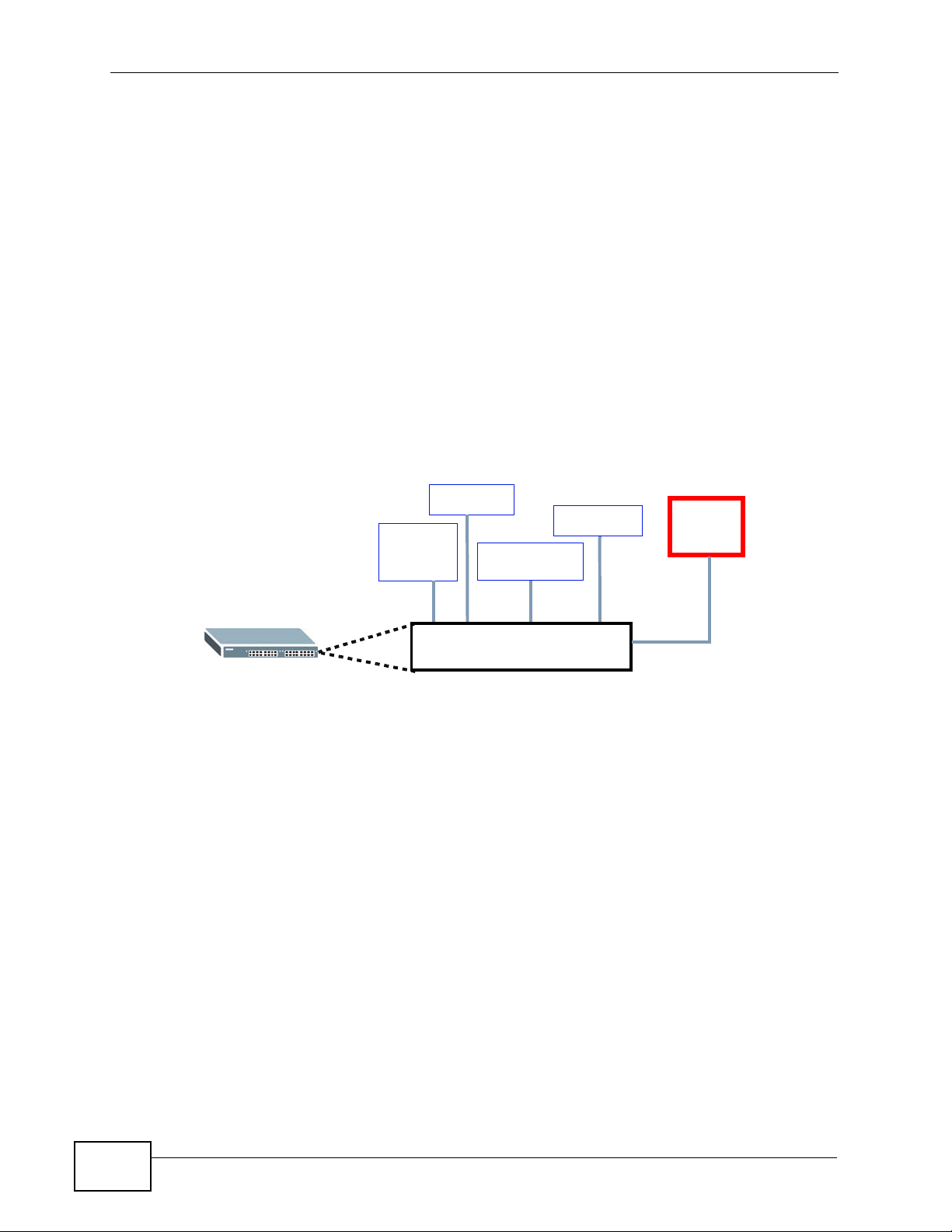
3.1.5.1 Connect a Sensor to the ALARM Slot
This section shows you how to connect up to four sensors to the ALARM slot and
to let a bell signal the alarm, as shown in the diagram below.
Figure 14 Connecting Sensors to the ALARM connector
Smoke
Flooding
Forced
Entry
Movement
Alarm
bell
ALARM Slot
Follow these steps to connect an external sensor device to the Switch.
1 Use a connector to connect wires of the correct gauge to the sensor’s power
output pins. See Chapter 41 on page 335 for the wire specifications. Check the
sensor’s documentation to identify its two power output pins.
2 Connect these two wires to any one of the following pairs of power input pins on
the Switch’s ALARM connector--(4,5) (6,7) (8,9) (10,11). The pin numbers run
from the right side of the connector to the left.
2a Connect each of the sensor’s two power output wires to the ALARM
connector by depressing the spring clip corresponding to the pin you are
connecting to.
2b Insert the wire and release the spring clip.
2c Repeat the process for the sensor’s other power output wire. A total of four
sensors may be connected to the ALARM connector in this way using the
remaining power input pins.
38
MES-3528 User’s Guide
Page 39
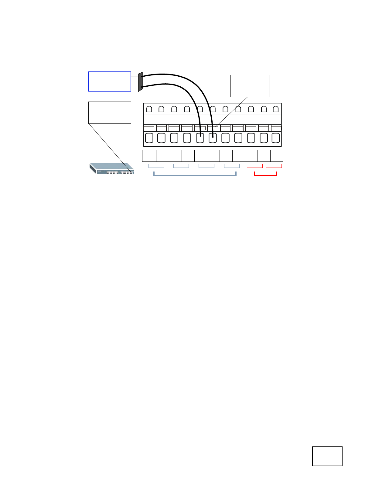
3 Insert the alarm connector into the ALARM slot.
Figure 15 Connecting a Sensor to the ALARM Slot
Chapter 3 Hardware Overview
Smoke
Detector
Spring
Clip
ALARM
Connector
12311 10 45698710
Alarm Input Pins
4 To connect an output device such as an alarm bell, repeat the previous steps but
this time connect to either pins (1,2) or (2,3) on the ALARM connector.
You can also daisy-chain the external alarm to another ZyXEL Switch which
supports the external alarm feature. If daisy-chaining to a ZyXEL switch that is a
different model, check your switch’s documentation for the correct pin
assignments.
Alarm Output Pins
1 Use wires of the correct gauge to connect either of the power output pin pairs (1-
normal close, 2-common) or (2-common, 3-normal open) on the ALARM
connector to the input power pin pairs of an ALARM connector on another ZyXEL
Switch.
MES-3528 User’s Guide
39
Page 40
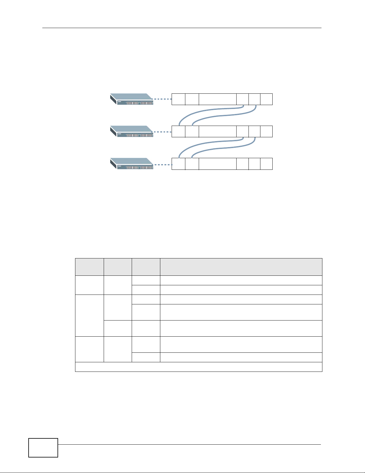
Chapter 3 Hardware Overview
2 When daisy-chaining further Switches ensure that the output power pins you use
are the same as those you used when connecting to the first switch, as shown in
the diagram below.
Figure 16 Daisy-chaining an External Alarm Sensor to Other Switches of the Same
Model
3.2 LEDs
After you connect the power to the Switch, view the LEDs to ensure proper
functioning of the Switch and as an aid in troubleshooting.
Table 2 LED Descriptions
LED COLOR
PWR Green On The system is turned on.
SYS Green On The system is on and functioning properly.
ALM Red On A hardware failure is detected, or an external alarm is
Ethernet Ports
.........
.........
.........
12311 10
12311 10
12311 10
Pin Assignments
STATU
S
Off The system is off.
Blinking The system is rebooting and performing self-diag nostic
Off The power is off or the system is not ready/
Off The system is functioning normally.
DESCRIPTION
tests.
malfunctioning.
active.
40
MES-3528 User’s Guide
Page 41

Chapter 3 Hardware Overview
Table 2 LED Descriptions (continued)
LED COLOR
1 ~ 24 Green Blinking The system is transmitting/receiving to/from a 10 Mbps
Amber Blinking The system is transmitting/receiving to/from a 100 Mbps
Mini-GBIC Slots
LNK Green On The link to this port is up.
ACT Green Blinking This port is receiving or transmitting data.
1000Base-T Ethernet Ports (in Dual Personality Interface)
LNK/ACT Green Blinking The system is transmitting/receiving to/from a 10 Mbps or
Amber Blinking The system is transmitting/receiving to/from a 100 Mbps
FDX Amber On The Gigabit port is negotiating in full-duplex mode.
STATU
S
on The link to a 10 Mbps Ethernet network is up.
On The link to a 100 Mbps Ethernet network is up.
Off The link to an Ethernet network is down.
Off The link to this port is not connected.
On The link to a 10 Mbps or a 1000 Mbps Ethernet network is
On The link to a 100 Mbps Ethernet network is up.
Off The link to an Ethernet network is down.
Off The Gigabit port is negotiating in half-duplex mode.
DESCRIPTION
Ethernet network.
Ethernet network.
a 1000 Mbps Ethernet network.
up.
Ethernet network.
MES-3528 User’s Guide
41
Page 42

Chapter 3 Hardware Overview
42
MES-3528 User’s Guide
Page 43

PART II
Basic Configuration
The Web Configurator (45)
Initial Setup Example (55)
System Status and Port Statistics (71)
Basic Setting (77)
43
Page 44

44
Page 45

CHAPTER 4
The Web Configurator
This section introduces the configuration and functions of the web configurator.
4.1 Introduction
The web configurator is an HTML-based managem ent interface that allows easy
Switch setup and management via Inter n et br ows e r. Use Internet Explorer 6.0
and later or Netscape Navigator 7.0 and later versions. The recommended screen
resolution is 1024 by 768 pixels.
In order to use the web configurator you need to allow:
• Web browser pop -up windows from your device. W eb pop-up blocking i s enabled
by default in Windows XP SP (Service Pack) 2.
• JavaScript (enabled by default).
• Java permissions (enabled by default).
4.2 System Login
1 Start your web browser.
2 Type “http://” and the IP address of the Switch (for example, the default
management IP address is 192.168.1.1) in the Location or Address field. Press
[ENTER].
MES-3528 User’s Guide
45
Page 46
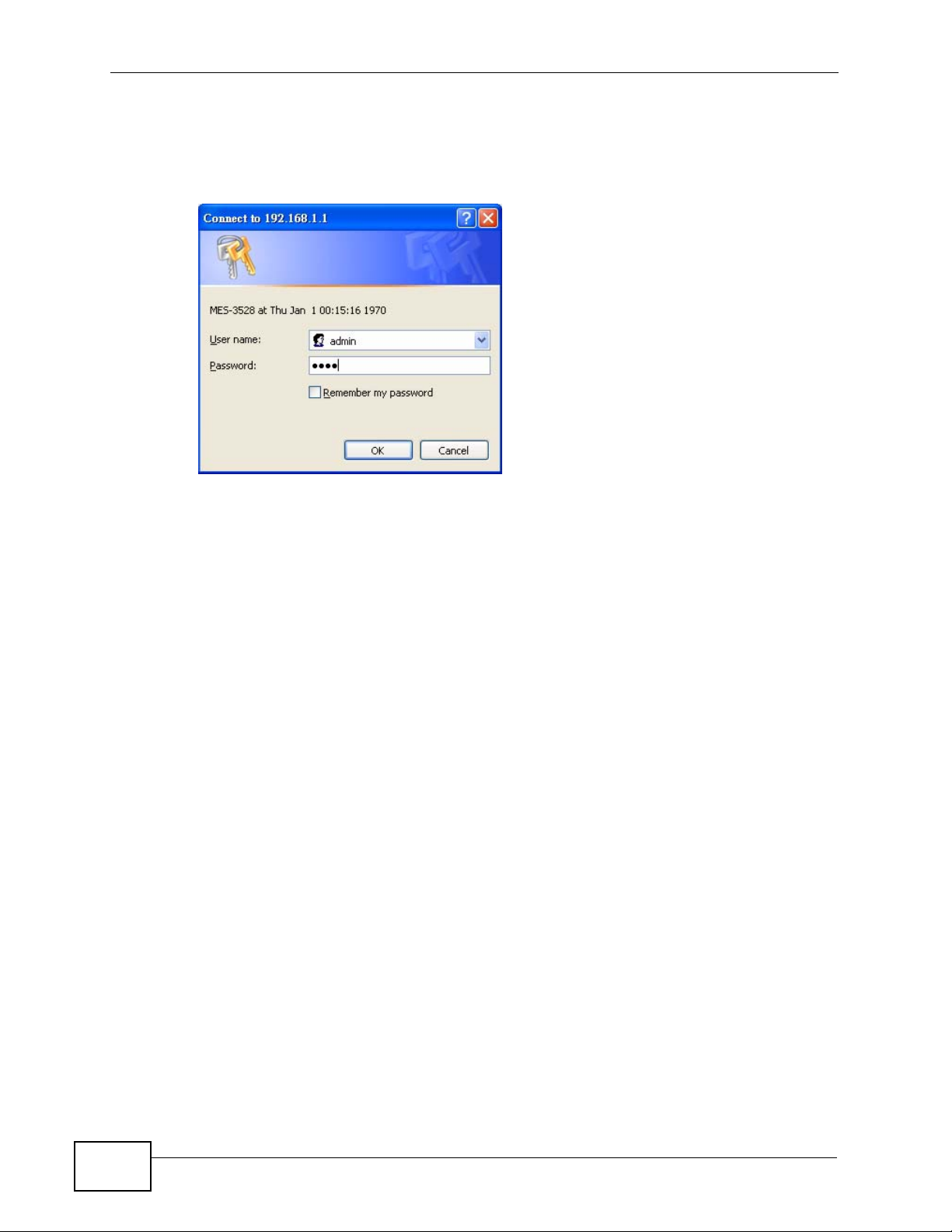
Chapter 4 The Web Configurator
3 The login screen appears. The default username is admin and associated default
password is 1234. The date and time display as shown if you hav e not configured
a time server nor manually entered a time and date in the General Setup screen.
Figure 17 Web Configurator: Login
4 Click OK to view the first web configurator screen.
4.3 The Status Screen
The Status screen is the first screen that displays when you access the web
configurator.
46
MES-3528 User’s Guide
Page 47
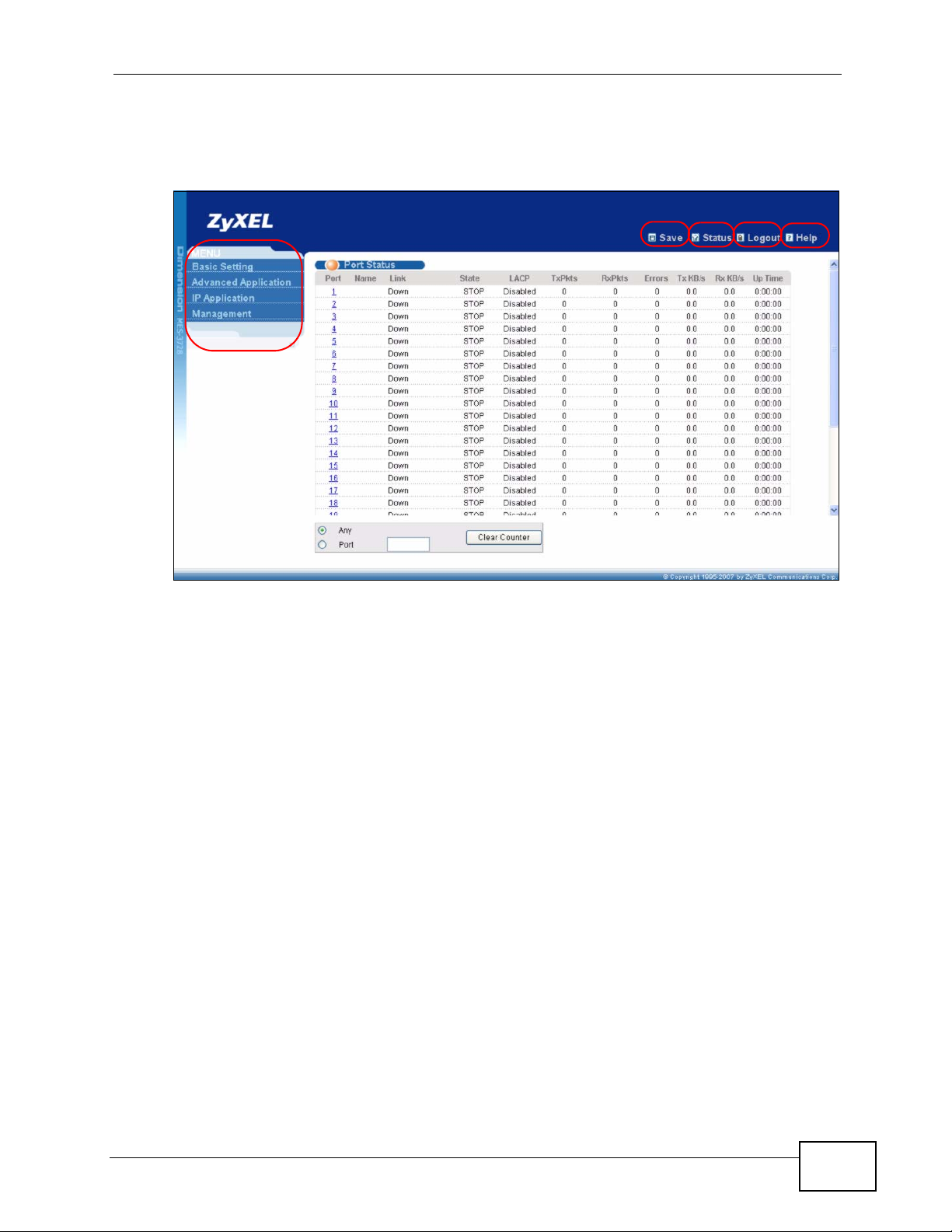
Chapter 4 The Web Configurator
The following figure shows the navigating components of a web configurator
screen.
Figure 18 Web Configurator Home Screen (Status)
B
C
DE
A
A - Click the menu items to open submenu links, and then click on a submenu link
to open the screen in the main window.
B, C, D, E - These are quick links which allow you to perform certain tasks no
matter which screen you are currently working in.
B - Click this link to save your configuration into the Switch’s nonvolatile memory.
Nonvolatile memory is the configuration of y our Switch that stays the same even if
the Switch’s power is turned off.
C - Click this link to go to the status page of the Switch.
D - Click this link to logout of the web configurator.
E - Click this link to display web help pages. The help pages provide descriptions
for all of the configuration screens.
MES-3528 User’s Guide
47
Page 48
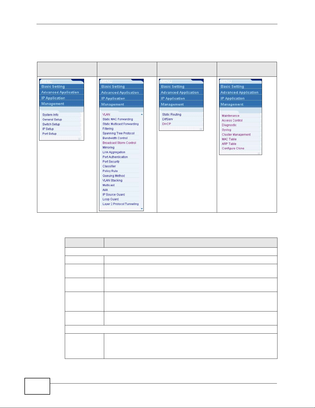
Chapter 4 The Web Configurator
In the navigation panel, click a main link to reveal a list of submenu links.
Table 3 Navigation Panel Sub-links Overview
BASIC SETTING
ADVANCED
APPLICATION
IP APPLICATION MANAGEMENT
The following table describes the links in the navigation panel.
Table 4 Navigation Panel Links
LINK DESCRIPTION
Basic Settings
System Info This link takes you to a screen that displays general system information.
General Setup This link takes you to a screen where you can configure general
identification information about the Switch.
Switch Setup This link takes you to a screen where you can set up global Switch
parameters such as VLAN type, GARP and priority queues.
IP Setup This link takes you to a screen where you can configure the IP address,
subnet mask (necessary for Switch management) and DNS (domain
name server) and set up to 64 IP routing domains.
Port Setup This link takes you to a screen where you can configure settings for
individual Switch ports.
Advanced Application
VLAN This link takes you to screens where you can configure port-based or
802.1Q VLAN (depending on what you configured in the Switch Setup
menu). You can also configure a protocol based VLAN or a subnet based
VLAN in these screens.
48
MES-3528 User’s Guide
Page 49

Chapter 4 The Web Configurator
Table 4 Navigation Panel Links (continued)
LINK DESCRIPTION
Static MAC
Forwarding
Static
Multicast
Forwarding
Filtering This link takes you to a screen to set up filtering rules.
Spanning Tree
Protocol
Bandwidth
Control
Broadcast
Storm Control
Mirroring This link takes you to screens where you can copy traffic from one port
Link
Aggregation
Port
Authentication
Port Security This link takes you to screens where you can activate MAC address
Classifier This link takes you to a screen where you can configure the Switch to
Policy Rule This link takes you to a screen where you can configure the Switch to
Queuing
Method
VLAN Stacking This link takes you to screens where you can configure VLAN stacking.
Multicast This link tak es you to screens where you can configure v arious multicast
AAA This link takes you to a screen where you can configure authentication,
IP Source
Guard
Loop Guard This link takes you to a screen where you can configure protection
Layer 2
Protocol
Tunneling
IP Application
This link takes you to a screen where you can configure static MAC
addresses for a port. These static MAC addresses do not age out.
This link takes you to a screen where you can configure static multicast
MAC addresses for port(s). These static multicast MAC addresses do not
age out.
This link takes you to screens where you can configure the RSTP/MRSTP/
MSTP to prevent network loops.
This link takes you to a screen where you can configure bandwidth limits
on the Switch.
This link takes you to a screen to set up broadcast filters.
or ports to another port in order that you can examine the traffic from
the first port without interference.
This link takes you to screens where you can logically aggregate physical
links to form one logical, higher-bandwidth link.
This link takes you to a screen where you can configure IEEE 802.1x port
authentication for clients communicating via the Switch.
learning and set the maximum number of MAC addresses to learn on a
port.
group packets based on the specified criteria.
perform special treatment on the grouped packets.
This link takes you to a screen where you can configure queuing with
associated queue weights for each port.
features, IGMP snooping and create multicast VLANs.
authorization and accounting services via external servers. The external
servers can be either RADIUS (Remote Au thentication Dial-In User
Service) or TACACS+ (Terminal Access Controller Access-Control System
Plus).
This link takes you to screens where you can configure filtering of
unauthorized DHCP and ARP packets in your network.
against network loops that occur on the edge of your network.
This link takes you to a screen where you can configure L2PT (Layer 2
Protocol Tunneling) settings on the Switch.
MES-3528 User’s Guide
49
Page 50

Chapter 4 The Web Configurator
Table 4 Navigation Panel Links (continued)
LINK DESCRIPTION
Static Routing This link takes you to a screen where you can configure static routes. A
static route defines how the Switch should forward traffic by configuring
the TCP/IP parameters manually.
DiffServ This link takes you to screens where you can enable DiffServ, configure
marking rules and set DSCP-to-IEEE802.1p mappings.
DHCP This link takes you to screens where you can configure the DHCP
settings.
Management
Maintenance This link takes you to screens where you can perform firmware and
configuration file maintenance as well as reboot the system.
Access Control This link takes you to screens where you can change the system login
password and configure SNMP and remote management.
Diagnostic This link takes you to a screen where you can view system logs and test
port(s).
Syslog This link takes you to screens where you can setup system logs and a
system log server.
Cluster
Management
MAC Table This link takes you to a screen where you can view the MAC addresses
ARP T able This link take s you to a screen where you can view the MAC addresses –
Configure
Clone
This link takes you to screens where you can configure clustering
management and view its status.
(and types) of devices attached to what ports and VLAN IDs.
IP address resolution table.
This link takes you to a screen where you can copy attributes of one port
to other ports.
50
MES-3528 User’s Guide
Page 51
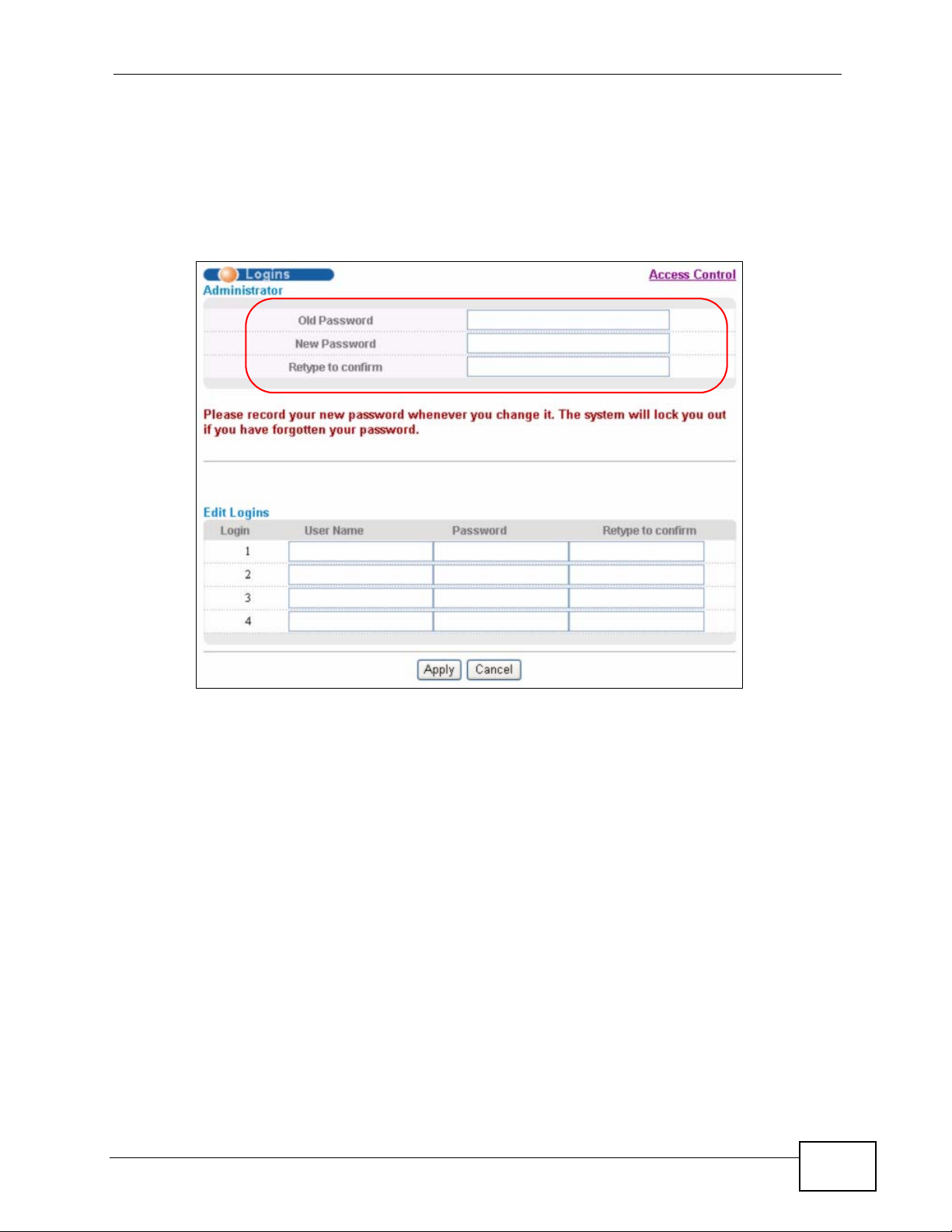
4.3.1 Change Your Password
After you log in for the first time, it is recommended you change the default
administrator password. Click Management > Access Control > Logins to
display the next screen.
Figure 19 Change Administrator Login Password
Chapter 4 The Web Configurator
4.4 Saving Your Configuration
When you are done modifying the settings in a screen, click Apply to save your
changes back to the run-time memory. Settings in the run-time memory are lost
when the Switch’s power is turned off.
Click the Save link in the upper right hand corner of the web configur ator to save
your configuration to nonvolatile memory. Nonvolatile memory refers to the
Switch’s storage that remains even if the Switch’s power is turned off.
Note: Use the Save link when you are done with a configuration session.
MES-3528 User’s Guide
51
Page 52

Chapter 4 The Web Configurator
4.5 Switch Lockout
You could block yourself (and all others) from managing the Switch if you do one
of the following:
1 Delete the management VLAN (default is VLAN 1).
2 Delete all port-based VLANs with the CPU port as a member. The “CPU port” is the
management port of the Switch.
3 Filter all traffic to the CPU port.
4 Disable all ports.
5 Misconfigure the text configuration file.
6 Forget the password and/or IP address.
7 Prevent all services from accessing the Switch.
8 Change a service port number but forget it.
Note: Be careful not to lock yourself and others out of the Switch.
4.6 Resetting the Switch
If you lock yourself (and others) from the Switch or forget the administrator
password, you will need to reload the factory-default configur ation file or reset the
Switch back to the factory defaults.
4.6.1 Reload the Configuration File
Uploading the factory-default configuration file replaces the current configuration
file with the factory-default configuration file. This means that you will lose all
previous configurations and the speed of the console port will be reset to the
default of 9600 bps with 8 data bits, no parity, one stop bit and flow control set to
none. The password will also be reset to “1234” and the IP address to
192.168.1.1.
52
To upload the configuration file, do the following:
1 Connect to the console port using a computer with terminal emulation software.
MES-3528 User’s Guide
Page 53

Chapter 4 The Web Configurator
2 Disconnect and reconnect the Switch’s power to begin a session. When you
reconnect the Switch’s power, you will see the initial screen.
3 When you see the message “Press any key to enter Debug Mode within 3
seconds ...” press any key to enter debug mode.
4 Type atlc after the “Enter Debug Mode” message.
5 Wait for the “Starting XMODEM upload” message before activating XMODEM
upload on your terminal.
6 After a configuration file upload, type atgo to restart the Switch.
Figure 20 Resetting the Switch: Via the Console Port
Bootbase Version: V1.04 | 12/15/2008 15:42:13
RAM: Size = 65536 Kbytes
DRAM POST: Testing: 65536K
OK
FLASH: AMD 64M *2
ZyNOS Version: V3.90(BHR.0)b0 | 12/24/2008 21:56:57
Press any key to enter debug mode within 3 seconds.
ras> atlc
Starting XMODEM upload (CRC mode)....
CCCCCCCCCCCCCCCC
Total 573440 bytes received.
Erasing..
................................................................
OK
ras> atgo
The Switch is now reinitialized with a default configuration file including the default
password of “1234”.
4.7 Logging Out of the Web Configurator
Click Logout in a screen to exit the web configurator. Y ou hav e to log in with your
password again after you log out. This is recommended after you finish a
management session for security reasons.
Figure 21 Web Configurator: Logout Screen
MES-3528 User’s Guide
53
Page 54

Chapter 4 The Web Configurator
4.8 Help
The web configurator’s online help has descriptions of individual screens and some
supplementary information.
Click the Help link from a web configurator screen to view an online help
description of that screen.
54
MES-3528 User’s Guide
Page 55

CHAPTER 5
Initial Setup Example
This chapter shows how to set up the Switch for an example network.
5.1 Overview
The following lists the configuration steps for the initial setup:
• Create a VLAN
• Set port VLAN ID
• Configure the Switch IP management address
5.1.1 Creating a VLAN
VLANs confine broadcast frames to the VLAN group in which the port(s) belongs.
You can do this with port-based VLAN or tagged static VLAN with fixed port
members.
In this example, you want to configure port 1 as a member of VLAN 2.
Figure 22 Initial Setup Network Example: VLAN
MES-3528 User’s Guide
55
Page 56
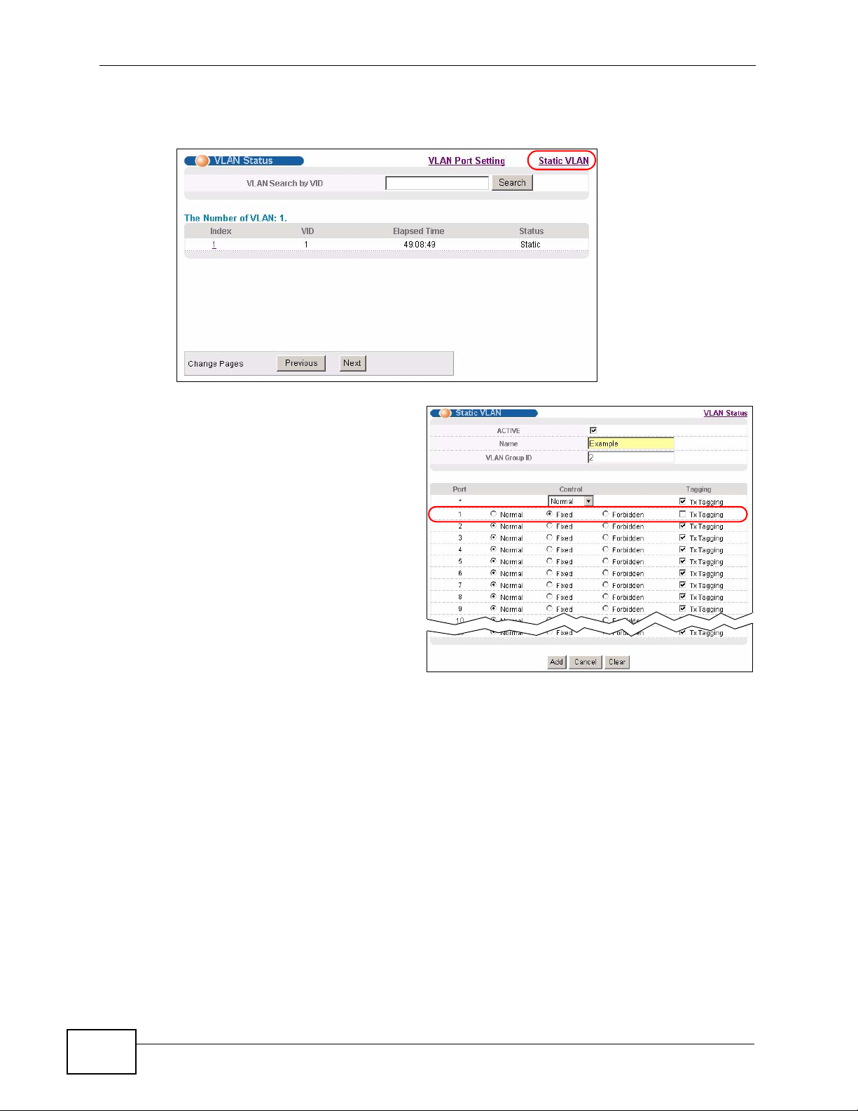
Chapter 5 Initial Setup Example
1 Click Advanced Application > VLAN in the navigation panel and click the Static
VLAN link.
2 In the Static VLAN screen,
select ACTIVE, enter a
descriptive name in the Name
field and enter 2 in the VLAN
Group ID field for the VLAN2
network.
56
Note: The VLAN Group ID field in this screen and the VID field in the IP Setup
screen refer to the same VLAN ID.
3 Since the VLAN2 network is connected to port 1 on the Switch, select Fixed to
configure port 1 to be a permanent member of the VLAN only.
4 To ensure that VLAN-unaware devices (such as computers and hubs) can receive
frames properly, clear the TX Tagging check box to set the Switch to remove
VLAN tags before sending.
5 Click Add to save the settings to the run-time memory. Settings in the run-time
memory are lost when the Switch’s power is turned off.
MES-3528 User’s Guide
Page 57
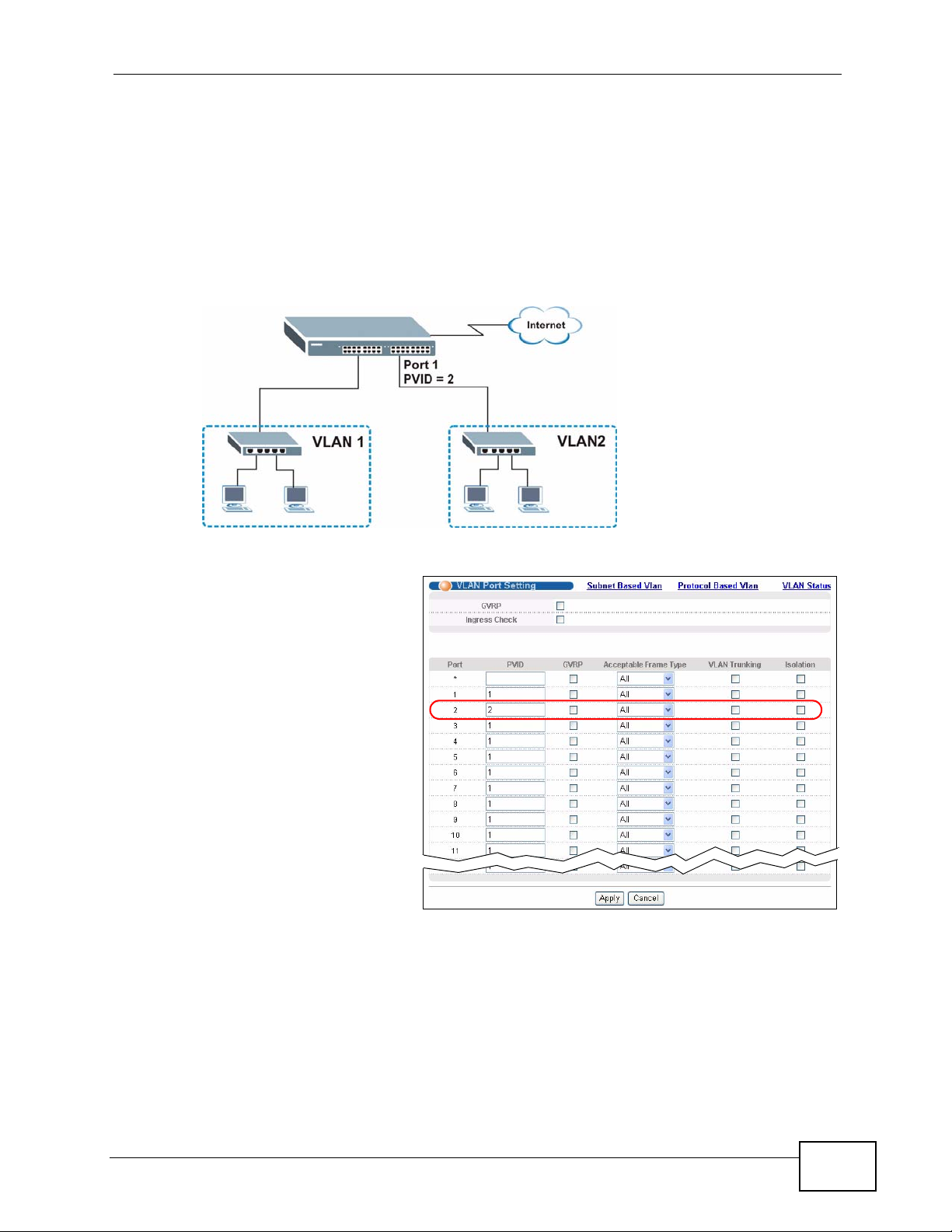
5.1.2 Setting Port VID
Use PVID to add a tag to incoming untagged frames received on that port so that
the frames are forwarded to the VLAN group that the tag defines.
In the example network, configure 2 as the port VID on port 1 so that any
untagged frames received on that port get sent to VLAN 2.
Figure 23 Initial Setup Network Example: Port VID
Chapter 5 Initial Setup Example
1 Click Advanced
Applications > VLAN in
the navigation panel. Then
click the VLAN Port
Setting link.
2 Enter 2 in the PVID field
for port 1 and click Apply
to save your changes back
to the run-time memory.
Settings in the run-time
memory are lost when the
Switch’s power is turned
off.
MES-3528 User’s Guide
57
Page 58
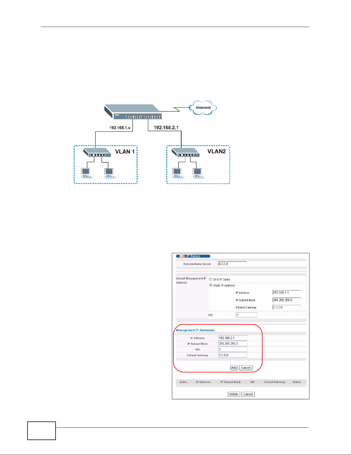
Chapter 5 Initial Setup Example
5.2 Configuring Switch Management IP Address
The default management IP address of the Switch is 192.168.1.1. You can
configure another IP address in a different subnet for management purposes. The
following figure shows an example.
Figure 24 Initial Setup Example: Management IP Address
1 Connect your computer to any Ethernet port on the Switch. Make sure your
computer is in the same subnet as the Switch.
2 Open your web browser and enter 192.168.1.1 (the default IP address) in the
address bar to access the web configurator. See Section 4.2 on page 45 for more
information.
3 Click Basic Setting > IP Setup
in the navigation panel.
4 Configure the related fields in the
IP Setup screen.
5 For the VLAN2 network, enter
192.168.2.1 as the IP address
and 255.255.255.0 as the subnet
mask.
6 In the VID field, enter the ID of
the VLAN group to which you
want this management IP
address to belong. This is the
same as the VLAN ID you
configure in the Static VLAN
screen.
58
MES-3528 User’s Guide
Page 59

Chapter 5 Initial Setup Example
7 Click Add to save your changes back to the run-time memory. Settings in the run-
time memory are lost when the Switch’s power is turned off.
MES-3528 User’s Guide
59
Page 60

Chapter 5 Initial Setup Example
60
MES-3528 User’s Guide
Page 61
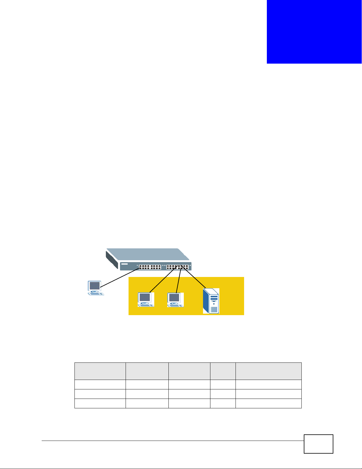
CHAPTER 6
Tutorials
This chapter provides some examples of using the web configurator to set up and
use the Switch. The tutorials include:
• How to Use DHCP Snooping on the Switch
• How to Use DHCP Relay on the Switch
6.1 How to Use DHCP Snooping on the Switch
You only wan t DHCP server A connected to port 5 to assign IP addresses to all
devices in VLAN network (V). Create a VLAN containing ports 5, 6 and 7. Con nect
a computer M to the Switch for management.
Figure 25 Tutorial: DHCP Snooping Tutorial Overview
M
V
C
Note: For related information about DHCP snooping, see Section 26.1 on page 223.
The settings in this tutorial are as the following.
Table 5 Tutorial: Settings in this Tutorial
HOST
DHCP Server (A) 5 1 and 100 100 Yes
DHCP Client (B) 6 1 and 100 100 No
DHCP Client (C) 7 1 and 100 100 No
PORT
CONNECTED
B
VLAN PVID
A
DHCP SNOOPING
PORT TRUSTED
MES-3528 User’s Guide
61
Page 62

Chapter 6 Tutorials
1 Access the Switch through http://192.168.1.1 by default. Log into the Switch
by entering the username (default: admin) and password (default: 1234).
2 Go to Advanced Application > VLAN > Static VLAN, and create a VLAN with ID
of 100. Add ports 5, 6 and 7 in the VLAN by selecting Fixed in the Control field as
shown.
Deselect Tx Tagging because you don’t want outgoing traffic to contain this VLAN
tag.
Click Add.
Figure 26 Tutorial: Create a VLAN and Add Ports to It
62
MES-3528 User’s Guide
Page 63
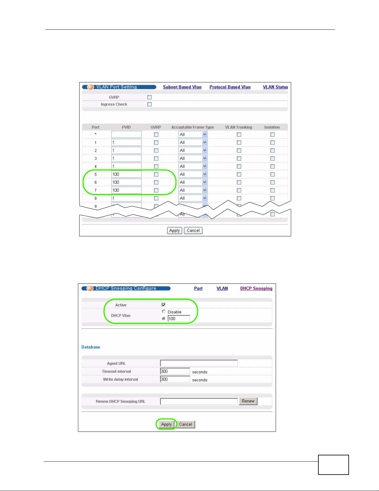
Chapter 6 Tutorials
3 Go to Advanced Application > VLAN > VLAN Port Setting, and set the PVID
of the ports 5, 6 and 7 to 100. This tags untagged incoming frames on ports 5, 6
and 7 with the tag 100.
Figure 27 Tutorial: Tag Untagged Frames
4 Go to Advanced Application > IP Source Guard > DHCP snooping >
Configure, activate and specify VLAN 100 as the DHCP VLAN as shown. Click
Apply.
Figure 28 Tutorial: Specify DHCP VLAN
MES-3528 User’s Guide
63
Page 64
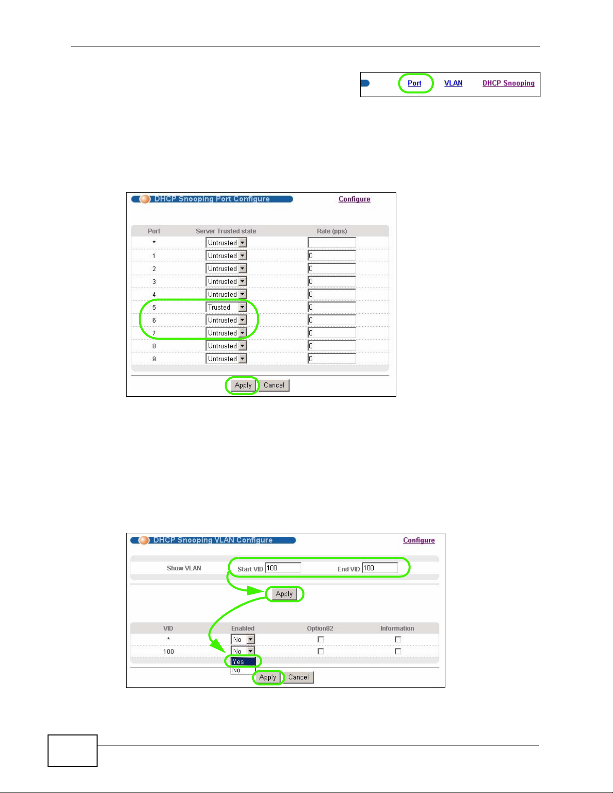
Chapter 6 Tutorials
5 Click the Port link at the top right corner.
6 The DHCP Snooping Port Configure screen appears. Select Trusted in the
Server Trusted state field for port 5 because the DHCP server is connected to
port 5. Keep ports 6 and 7 Untrusted because they are connected to DHCP
clients. Click Apply.
Figure 29 Tutorial: Set the DHCP Server Port to Trusted
7 Go to Advanced Application > IP Source Guard > DHCP snooping >
Configure > VLAN, show VLAN 100 by entering 100 in the Start VID and End
VID fields and click Apply. Then select Yes in the Enabled field of the VLAN 100
entry shown at the bottom section of the screen.
If you want to add more information in the DHCP request packets such as source
VLAN ID or system name, you can also select the Option82 and Information
fields in the entry. See Section 26.1.1.3 on page 225.
Figure 30 Tutorial: Enable DHCP Snooping on this VLAN
64
MES-3528 User’s Guide
Page 65
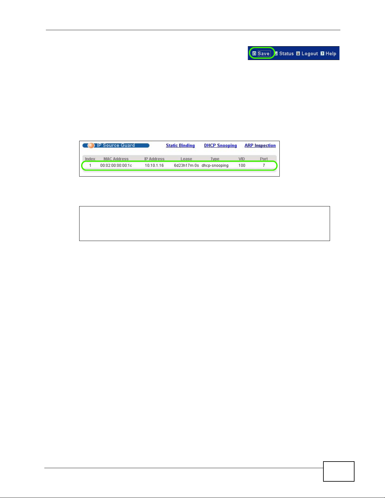
Chapter 6 Tutorials
8 Click Save at the top right corner of the web
configurator to save the configuration permanently.
9 Connect your DHCP server to port 5 and a computer (as DHCP client) to either
port 6 or 7. The computer should be able to get an IP address from the DHCP
server. If you put the DHCP server on port 6 or 7, the computer will not able to get
an IP address.
10 To check if DHCP snooping works, go to Advanced Application > IP Source
Guard, you should see an IP assignment with the type dhcp-snooping as shown.
Figure 31 Tutorial: Check the Binding If DHCP Snooping Works
You can also telnet or log into the Switch’s console. Use the command “ show dhcp
snooping binding” to see the DHCP snooping binding table as shown next.
sysname# show dhcp snooping binding
MacAddress IpAddress Lease Type VLAN Port
----------------- --------------- ------------ ------------- ---- ---- 00:02:00:00:00:1c 10.10.1.16 6d23h59m20s dhcp-snooping 100 7
Total number of bindings: 1
6.2 How to Use DHCP Relay on the Switch
This tutorial describes how to configure your Switch to forward DHCP client
requests to a specific DHCP server. The DHCP server can then assign a specific IP
address based on the information in the DHCP requests.
6.2.1 DHCP Relay Tutorial Introduction
In this example, you have configured your DHCP server (192.168.2.3) and want to
have it assign a specific IP address (say 172.16.1.18) to DHCP client A based on
MES-3528 User’s Guide
65
Page 66
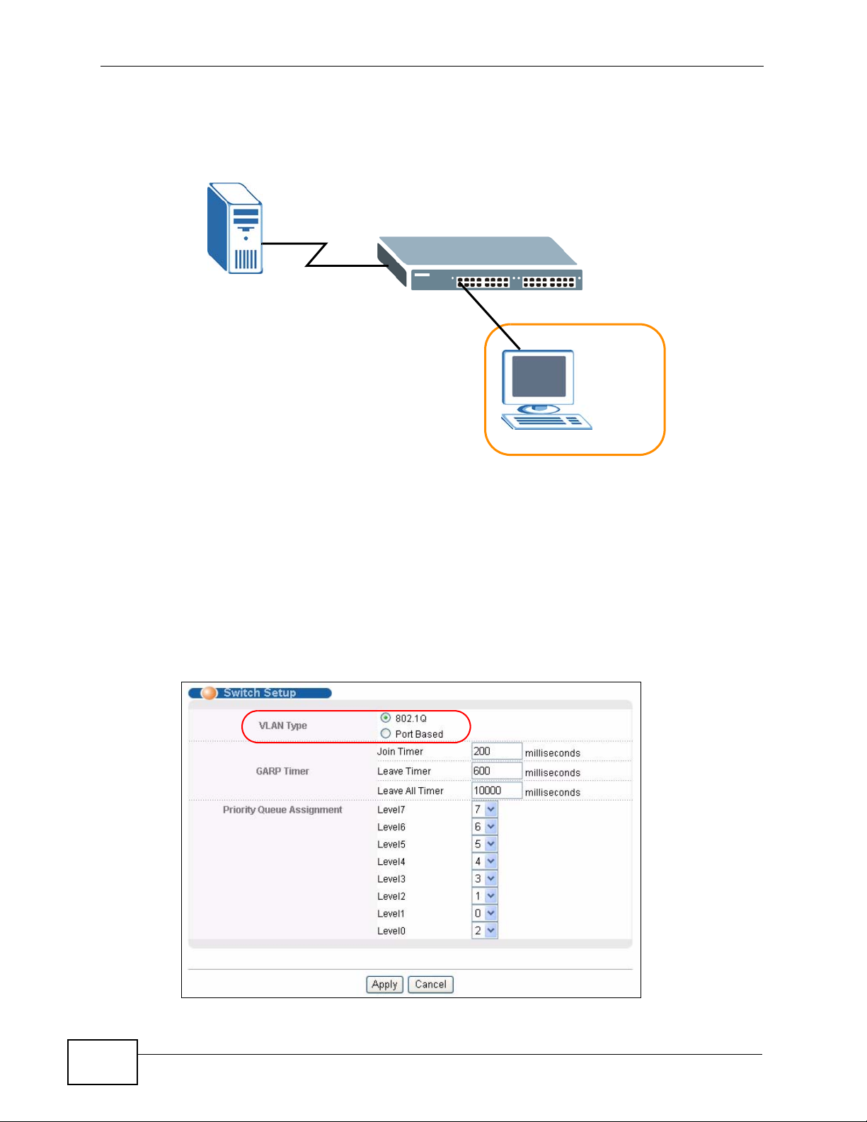
Chapter 6 Tutorials
the system name, VLAN ID and port number in the DHCP request. Client A
connects to the Switch’s port 2 in VLAN 102.
Figure 32 Tutorial: DHCP Relay Scenario
DHCP Server
192.168.2.3
Port 2
PVID=102
A
VLAN 102
172.16.1.18
6.2.2 Creating a VLAN
Follow the steps below to configure port 2 as a member of VLAN 102.
1 Access the web configurator through the Switch’s management port.
2 Go to Basic Setting > Switch Setup and set the VLAN type to 802.1Q. Click
Apply to save the settings to the run-time memory.
Figure 33 Tutorial: Set VLAN Type to 802.1Q
66
MES-3528 User’s Guide
Page 67
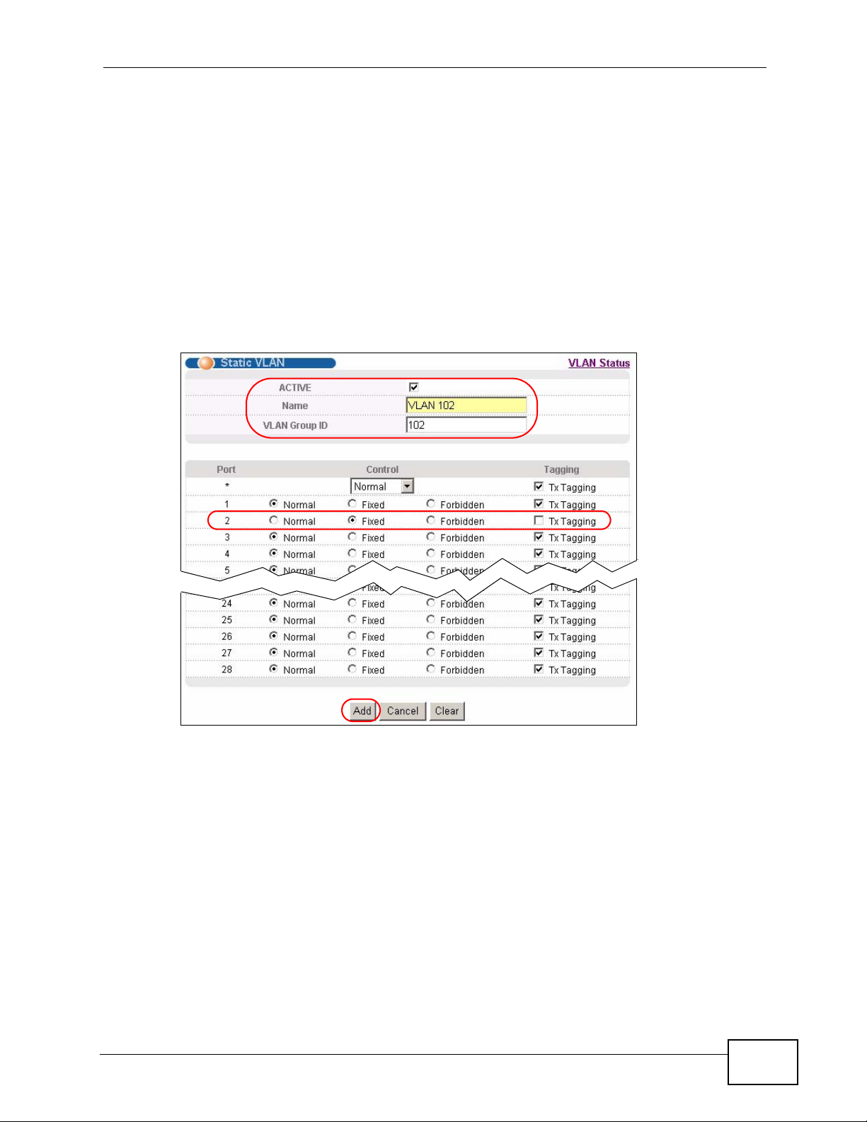
Chapter 6 Tutorials
3 Click Advanced Application > VLAN > Static VLAN.
4 In the Static VLAN screen, select ACTIVE, enter a descriptive name (VALN 102
for example) in the Name field and enter 102 in the VLAN Group ID field.
5 Select Fixed to configure port 2 to be a permanent member of this VLAN.
6 Clear the TX Tagging check box to set the Switch to remove VLAN tags before
sending.
7 Click Add to save the settings to the run-time memory. Settings in the run-time
memory are lost when the Switch’s power is turned off.
Figure 34 Tutorial: Create a Static VLAN
MES-3528 User’s Guide
67
Page 68
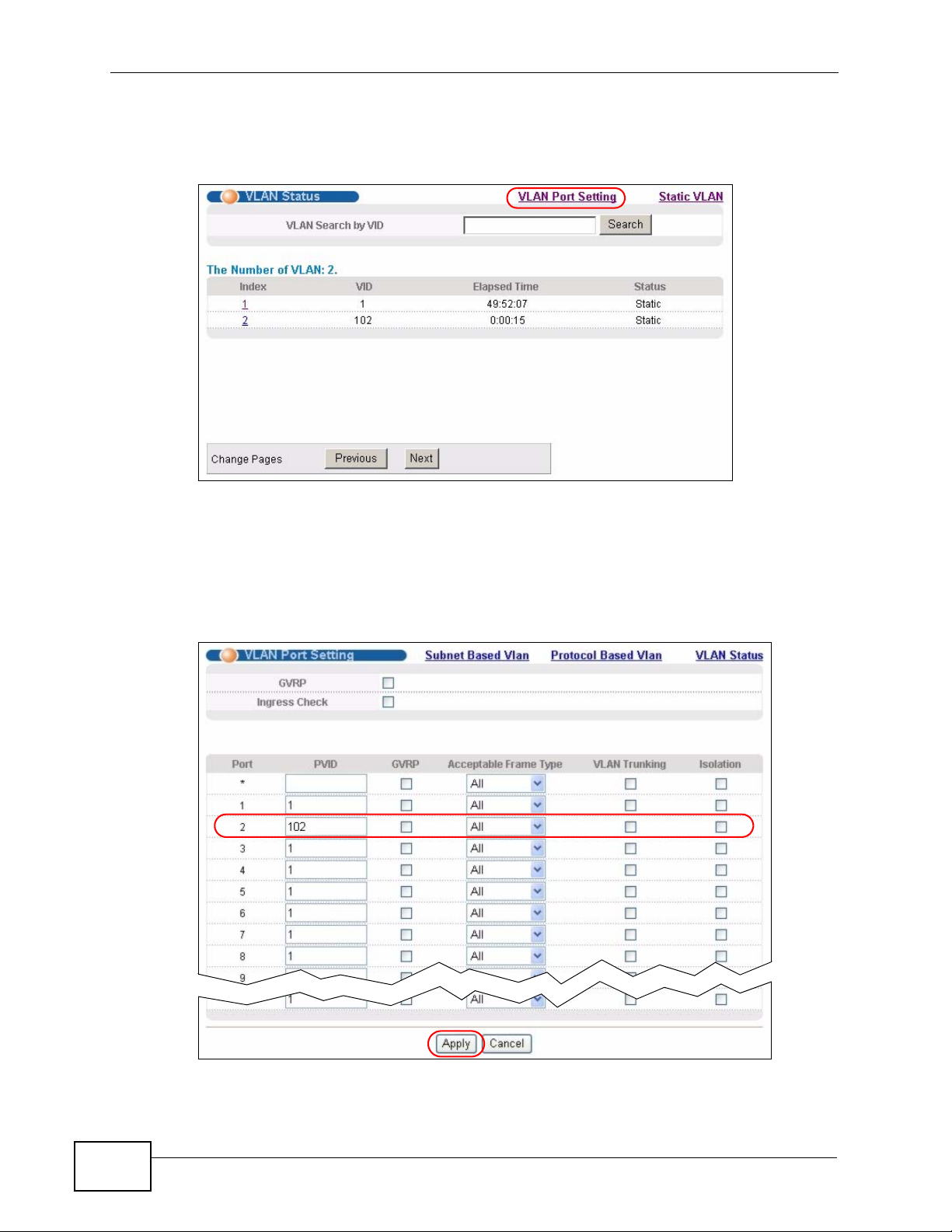
Chapter 6 Tutorials
8 Click the VLAN Status link in the Static VLAN screen and then the VLAN Port
Setting link in the VLAN Status screen.
Figure 35 Tutorial: Click the VLAN Port Setting Link
9 Enter 102 in the PVID field for port 2 to add a tag to incoming untagged frames
received on that port so that the frames are forwarded to the VLAN group that the
tag defines.
10 Click Apply to save your changes back to the run-time memory.
Figure 36 Tutorial: Add Tag for Frames Received on Port 2
68
MES-3528 User’s Guide
Page 69
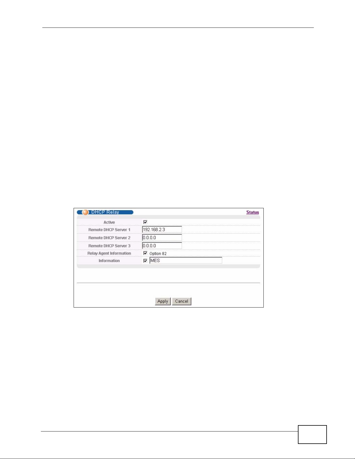
11 Click the Save link in the upper right corner of the web configurator to save your
configuration permanently.
6.2.3 Configuring DHCP Relay
Follow the steps below to enable DHCP relay on the Switch and allow the Switch to
add relay agent information (such as the VLAN ID) to DHCP requests.
1 Click IP Application > DHCP and then the Global link to open the DHCP Relay
screen.
2 Select the Active check box.
3 Enter the DHCP server’s IP address (192.168.2.3 in this example) in the Remote
DHCP Server 1 field.
4 Select the Option 82 and the Information check boxes.
Chapter 6 Tutorials
5 Click Apply to save your changes back to the run-time memory.
Figure 37 Tutorial: Set DHCP Server and Relay Information
6 Click the Save link in the upper right corner of the web configurator to save your
configuration permanently.
7 The DHCP server can then assign a specific IP address based on the DHCP
request.
6.2.4 Troubleshooting
Check the client A’s IP address. If it did not receive the IP address 172.16.1.18,
make sure:
MES-3528 User’s Guide
69
Page 70

Chapter 6 Tutorials
1 Client A is connected to the Switch’s port 2 in VLAN 102.
2 You configured the correct VLAN ID, port number and system name for DHCP relay
on both the DHCP server and the Switch.
3 You clicked the Save link on the Switch to have your settings take effect.
70
MES-3528 User’s Guide
Page 71

CHAPTER 7
System Status and Port
Statistics
This chapter describes the system status (web configurator home page) and port
details screens.
7.1 Overview
The home screen of the web configurator displays a port stati stical summary with
links to each port showing statistical details.
MES-3528 User’s Guide
71
Page 72
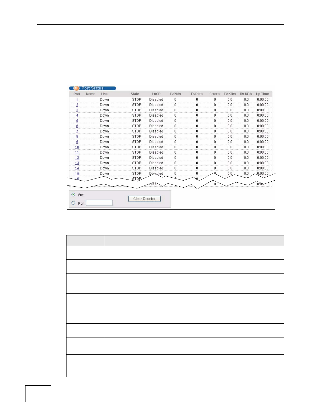
Chapter 7 System Status and Port Statistics
7.2 Port Status Summary
To view the port statistics, click Status in all web configurator screens to display
the Status screen as shown next.
Figure 38 Status
The following table describes the labels in this screen.
Table 6 Status
LABEL DESCRIPTION
Port This identifies the Ethernet port. Click a port number to display the Port
Details screen (refer to Figure 39 on page 73).
Name This is the name you assigned to this port in the Basic Setting > Port
Setup screen.
Link This field displays the speed (either 10M for 10Mbps, 100M for 100Mbps
or 1000M for 1000Mbps) and the duplex (F for full duplex or H for half).
It also shows the cable type (Copper or Fiber) for the combo ports.
State If STP (Spanning Tree Protocol) is enabled, this field displays the STP
state of the port (see Section 13.1 on page 121 for more information).
If STP is disabled, this field displays FORWARDING if the link is up,
otherwise, it displays STOP.
LACP This fields displays whether LACP (Link Aggregation Control Protocol) has
been enabled on the port.
TxPkts This field shows the number of transmitted frames on this port.
RxPkts This field shows the number of received frames on this port.
Errors This field shows the number of received errors on this port.
Tx KB/s This field shows the number of kilobytes per second transmitted on this
port.
72
MES-3528 User’s Guide
Page 73
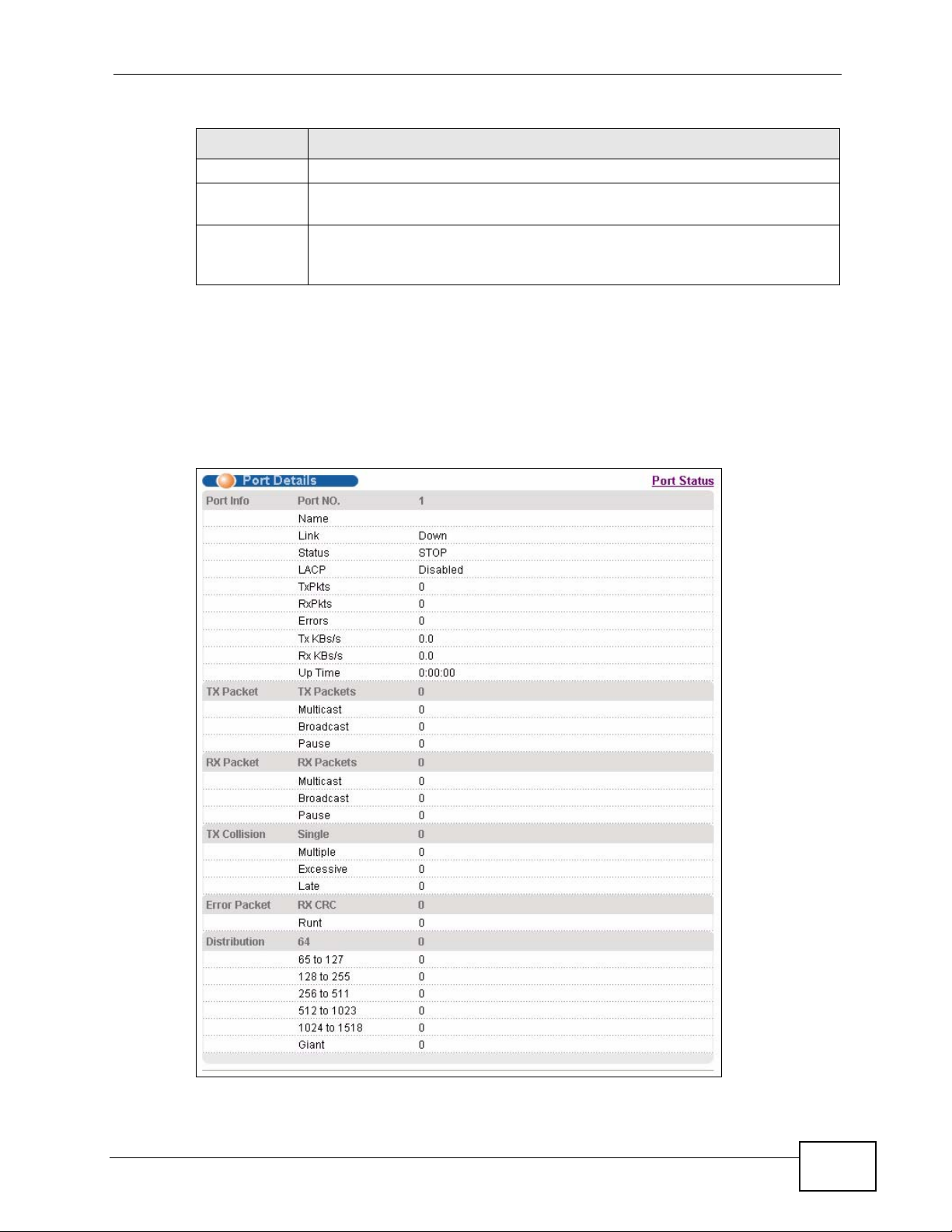
Table 6 Status (continued)
LABEL DESCRIPTION
Rx KB/s This field shows the number of kilobytes per second received on this port.
Up Time This field shows the total amount of time in hours, minutes and seconds
the port has been up.
Clear Counter Enter a port number and then click Clear Counter to erase the recorded
statistical information for that port, or select Any to clear statistics for all
ports.
7.2.1 Status: Port Details
Click a number in the Port column in the Status screen to display individual port
statistics. Use this screen to check status and detailed perf ormance data about an
individual port on the Switch.
Figure 39 Status > Port Details
Chapter 7 System Status and Port Statistics
MES-3528 User’s Guide
73
Page 74

Chapter 7 System Status and Port Statistics
The following table describes the labels in this screen.
Table 7 Status: Port Details
LABEL DESCRIPTION
Port Info
Port NO. This field displays the port number you are viewing.
Name This field displays the name of the port.
Link This field displays the speed (either 10M for 10Mbps, 100M for 100Mbps
or 1000M for 1000Mbps) and the duplex (F for full duplex or H for half
duplex). It also shows the cable type (Copper or Fiber).
Status If STP (Spanning Tree Protocol) is enabled, this field displays the STP state
of the port (see Section 13.1 on page 121 for more information).
If STP is disabled, this field displays FORWARDING if the link is up,
otherwise, it displays STOP.
LACP This field shows if LACP is enabled on this port or not.
TxPkts This field shows the number of transmitted frames on this port
RxPkts This field shows the number of received frames on this port
Errors This field shows the number of received errors on this port.
Tx KB/s This field shows the number kilobytes per second transmitted on this port.
Rx KB/s This field shows the number of kilobytes per second received on this port.
Up Time This field shows the total amount of time the connection has been up.
Tx Packet
The following fields display detailed information about packets transmitted.
TX Packet This field shows the number of good packets (unicast, multicast and
broadcast) transmitted.
Multicast This field shows the number of good multicast packets transmitted.
BroadcastThis field shows the number of good broadcast packets transmitted.
Pause This field shows the number of 802.3x Pause packets transmitted.
Rx Packet
The following fields display detailed information about packets received.
RX
Packet
Multicast This field shows the number of good multicast packets received.
BroadcastThis field shows the number of good broadcast packets received.
Pause This field shows the number of 802.3x Pause packets received.
TX Collision
The following fields display information on collisions while transmitting.
Single This is a count of successfully transmitted packets for which transmission is
Multiple This is a count of successfully transmitted packets for which transmission
This field shows the number of good packets (unicast, multicast and
broadcast) received.
inhibited by exactly one collision.
was inhibited by more than one collision.
74
MES-3528 User’s Guide
Page 75

Chapter 7 System Status and Port Statistics
Table 7 Status: Port Details (continued)
LABEL DESCRIPTION
ExcessiveThis is a count of packets for which transmission failed due to excessive
collisions. Excessive collision is defined as the number of maximum
collisions before the retransmission count is reset.
Late This is the number of times a late collision is detected, that is, after 512
bits of the packets have already been transmitted.
Error Packet The following fields display detailed information about packets received
that were in error.
RX CRC This field shows the number of packets received with CRC (Cyclic
Redundant Chec k) error(s).
Runt This field shows the number of packets received that were too short
(shorter than 64 octets), including the ones with CRC errors.
Distribution
64 This field shows the number of packets (including bad packets) received
that were 64 octets in length.
65-127 This field shows the number of packets (including bad packets) received
that were between 65 and 127 octets in length.
128-255 This field shows the number of packets (including bad packets) received
that were between 128 and 255 octets in length.
256-511 This field shows the number of packets (including bad packets) received
that were between 256 and 511 octets in length.
512-
1023
1024-
1518
Giant This field shows the number of packets (including bad packets) received
This field shows the number of packets (including bad packets) received
that were between 512 and 1023 octets in length.
This field shows the number of packets (including bad packets) received
that were between 1024 and 1518 octets in length.
that were between 1519 octets and the maximum frame size.
MES-3528 User’s Guide
The maximum frame size varies depending on your switch model. See
Chapter 41 on page 335.
75
Page 76

Chapter 7 System Status and Port Statistics
76
MES-3528 User’s Guide
Page 77
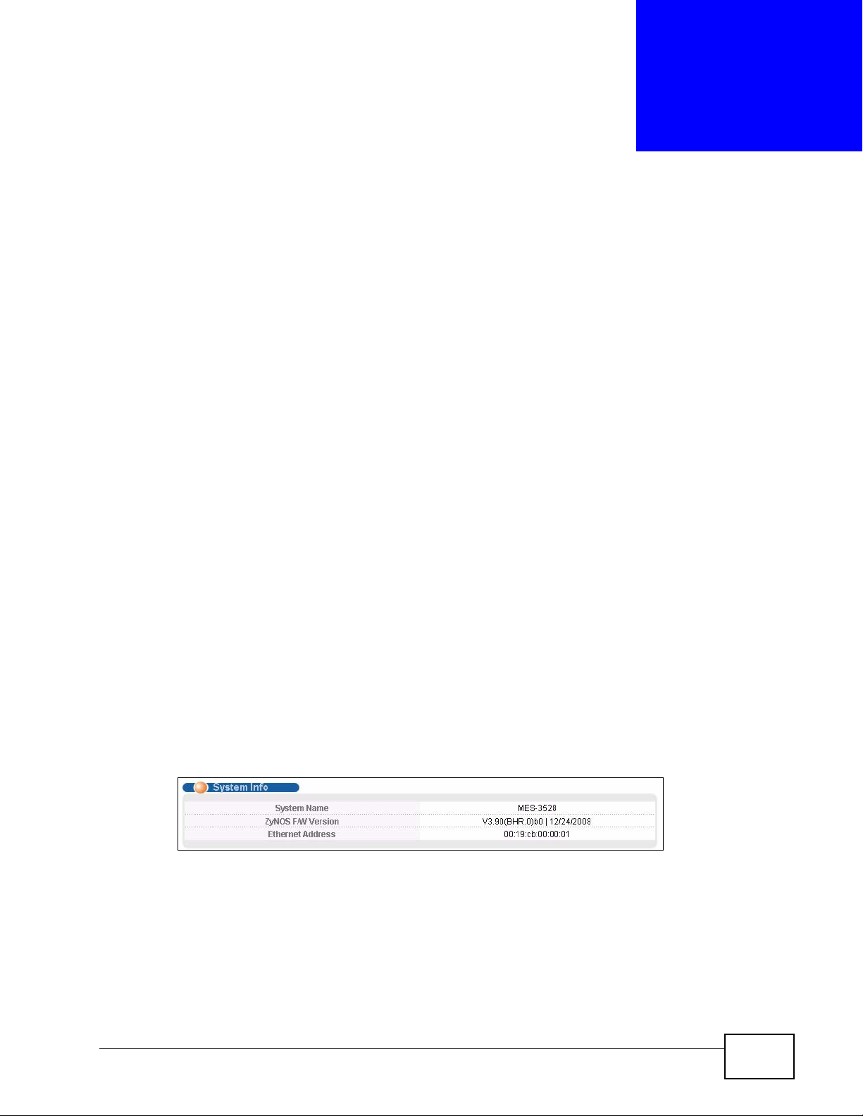
CHAPTER 8
Basic Setting
This chapter describes how to configure the System Info, General Setup,
Switch Setup, IP Setup and Port Setup screens.
8.1 Overview
The System Info screen displays general Switch information (such as firmware
version number). The General Setup screen allows you to configure general
Switch identification information. The General Setup screen also allows you to
set the system time manually or get the current time and date from an external
server when you turn on your Switch. The real time is then displayed in the Switch
logs. The Switch Setup screen allows you to set up and configure global Switch
features. The IP Setup screen allows you to configure a Switch IP address in each
routing domain, subnet mask(s) and DNS (domain name server) for management
purposes.
8.2 System Information
In the navigation panel, click Basic Setting > System Info to displa y the screen
as shown. You can check the firmware version number.
Figure 40 Basic Setting > System Info
MES-3528 User’s Guide
77
Page 78
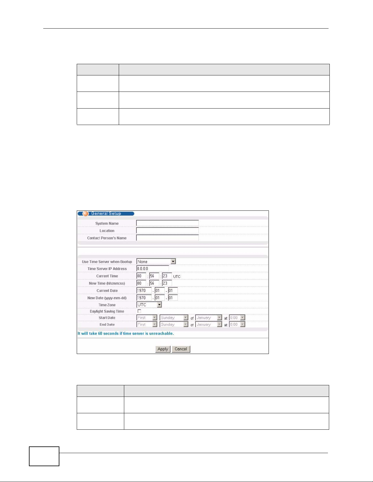
Chapter 8 Basic Setting
The following table describes the labels in this screen.
Table 8 Basic Setting > System Info
LABEL DESCRIPTION
System
Name
ZyNOS F/W
Version
Ethernet
Address
This field displays the descriptive name of the Switch for identification
purposes.
This field displays the version number of the Switch 's current firmware
including the date created.
This field refers to the Ethernet MAC (Media Access Control) address of the
Switch.
8.3 General Setup
Use this screen to configure general settings such as the system name and time.
Click Basic Setting > General Setup in the navigation panel to display the
screen as shown.
Figure 41 Basic Setting > General Setup
The following table describes the labels in this screen.
Table 9 Basic Setting > General Setup
LABEL DESCRIPTION
System Name Choose a descriptive name for identification purposes. This name
consists of up to 64 printable characters; spaces are allowed.
Location Enter the geographic location of your Switch. You can use up to 32
printable ASCII characters; spaces are allowed.
78
MES-3528 User’s Guide
Page 79

Chapter 8 Basic Setting
Table 9 Basic Setting > General Setup (continued)
LABEL DESCRIPTION
Contact
Person's Name
Use Time
Server when
Bootup
Time Server IP
Address
Current Time This field displays the time you open this menu (or refresh the menu).
New Time
(hh:min:ss)
Current Date This field displays the date you open this menu.
New Date
(yyyy-mm-dd)
Time Zone Select the time difference between UTC (Universal Time Coordinated,
Daylight
Saving Time
Enter the name of the person in charge of this Switch. You can use up to
32 printable ASCII characters; spaces are allowed.
Enter the time service protocol that your timeserver uses. Not all time
servers support all protocols, so you may have to use trial and error to
find a protocol that works. The main differences between them are the
time format.
When you select the Daytime (RFC 867) format, the Switch displays
the day, month, year and time with no time zone adjustment. When you
use this format it is recommended that you use a Daytime timeserver
within your geographical time zone.
Time (RFC-868) format displays a 4-byte integer giving the total
number of seconds since 1970/1/1 at 0:0:0.
NTP (RFC-1305) is similar to Time (RFC-868).
None is the default value. Enter the time manually. Each time you turn
on the Switch, the time and date will be reset to 1970-1-1 0:0:0.
Enter the IP address of your timeserver. The Switch searches for the
timeserver for up to 60 seconds. If you select a timeserver that is
unreachable, then this screen will appear locked for 60 seconds. Please
wait.
Enter the new time in hour, minute and second format. The new time
then appears in the Current Time field after you click Apply.
Enter the new date in year, month and day format. The new date then
appears in the Current Date field after you click Apply.
formerly known as GMT, Greenwich Mean Time) and your time zone from
the drop-down list box.
Daylight saving is a period from late spring to early fall when many
countries set their clocks ahead of normal local time by one hour to give
more daytime light in the evening.
Start Date Configure the day and time when Daylight Saving Time starts if you
MES-3528 User’s Guide
Select this option if you use Daylight Saving Time.
selected Daylight Saving Time. The time is displayed in the 24 hour
format. Here are a coupl e o f ex am ples:
Daylight Saving Time starts in most parts of the United States on the
second Sunday of March. Each time zone in the United States starts
using Daylight Saving Time at 2 A.M. local time. So in the United States
you would select Second, Sunday, March and 2:00.
Daylight Saving Time starts in the European Union on the last Sunday of
March. All of the time zones in the European Union start using Daylight
Saving Time at the same moment (1 A.M. GMT or UTC). So in the
European Union you would select Last, Sunday, March and the last
field depends on your time zone. In Germany for instance, you would
select 2:00 because Germany's time zone is one hour ahead of GMT or
UTC (GMT+1).
79
Page 80
Chapter 8 Basic Setting
Table 9 Basic Setting > General Setup (continued)
LABEL DESCRIPTION
End Date Configure the day and time when Daylight Saving Time ends if you
Apply Click Apply to save your changes to the Switch’s run-time memory. The
Cancel Click Cancel to begin configuring this screen afresh.
selected Daylight Saving Time. The time field uses the 24 hour
format. Here are a coupl e o f ex am ples:
Daylight Saving Time ends in the United States on the first Sunday of
November. Each time zone in the United States stops using Daylight
Saving Time at 2 A.M. local time. So in the United States you would
select First, Sunday, November and 2:00.
Daylight Saving Time ends in the European Union on the last Sunday of
October. All of the time zones in the European Union stop using Daylight
Saving Time at the same moment (1 A.M. GMT or UTC). So in the
European Union you would select Last, Sunday, October and the last
field depends on your time zone. In Germany for instance, you would
select 2:00 because Germany's time zone is one hour ahead of GMT or
UTC (GMT+1).
Switch loses these changes if it is turned off or loses power, so use the
Save link on the top navigation panel to save your changes to the nonvolatile memory when you are done configuring.
8.4 Introduction to VLANs
A VLAN (Virtual Local Area Network) allows a physical network to be partitioned
into multiple logical networks. Devices on a logical network belong to one group. A
device can belong to more than one group. With VLAN, a device cannot directly
talk to or hear from devices that are not in the same group(s); the traffic must
first go through a router.
In MTU (Multi-Tenant Unit) applications, VLAN is vital in providing isolation and
security among the subscribers. When properly configured, VLAN prevents one
subscriber from accessing the netw ork resources of another on the same LAN,
thus a user will not see the printers and hard disks of another user in the same
building.
VLAN also increases network performance by limiting broadcasts to a smaller and
more manageable logical broadcast domain. In traditional switched environments,
all broadcast packets go to each and every individual port. Wit h VLAN, all
broadcasts are confined to a specific broadcast domain.
Note: VLAN is unidirectional; it only governs outgoing traffic.
See Chapter 9 on page 91 for information on port-based and 802.1Q tagged
VLANs.
80
MES-3528 User’s Guide
Page 81
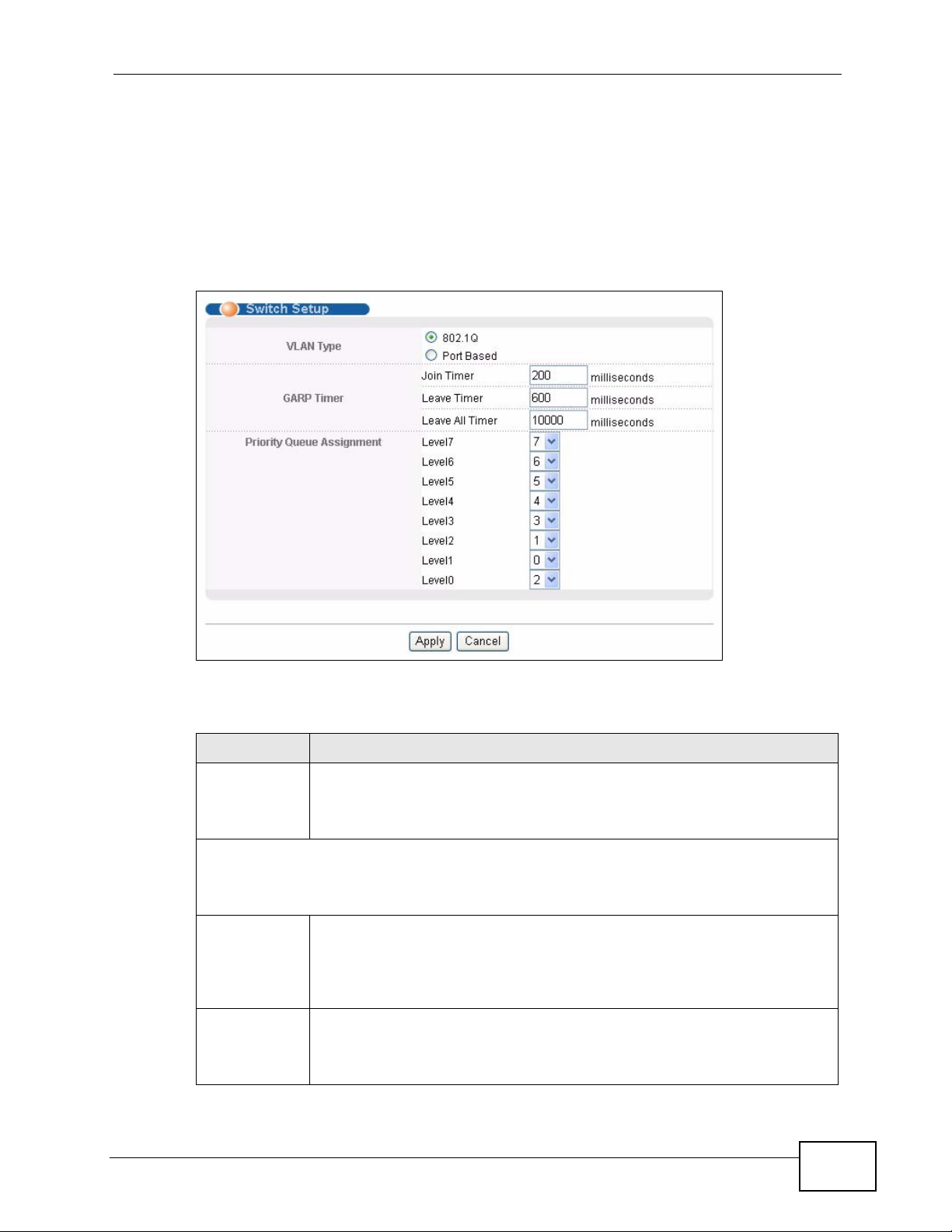
8.5 Switch Setup Screen
Click Basic Setting > Switch Setup in the navigation panel to display the screen
as shown. The VLAN setup screens change depending on whether you choose
802.1Q or Port Based in the VLAN Type field in this screen. R efer to the chapter on
VLAN.
Figure 42 Basic Setting > Switch Setup
Chapter 8 Basic Setting
The following table describes the labels in this screen.
Table 10 Basic Setting > Switch Setup
LABEL DESCRIPTION
VLAN Ty pe Choose 802.1Q or Port Based. The VLAN Setup screen changes
depending on whether you choose 802.1Q VLAN type or Port Based
VLAN type in this screen. See Chapter 9 on page 91 for more
information.
GARP Timer: Switches join VLANs by making a declaration. A declaration is made by
issuing a Join message using GARP. Declarations are withdrawn by issuing a Leave
message. A Leave All message terminates all registrations. GARP timers set declaration
timeout values. See the chapter on VLAN setup for more background information.
Join Timer Join Timer sets the duration of the Join Period timer for GVRP in
milliseconds. Each port has a Join Period timer. The allowed Join Time
range is between 100 and 65535 milliseconds; the default is 200
milliseconds. See the chapter on VLAN setup for more background
information.
Leave Timer Leave Time sets the duration of the Leave Period timer for GVRP in
milliseconds. Each port has a single Leave Period timer. Leave Time
must be two times larger than Join Timer; the default is 600
milliseconds.
MES-3528 User’s Guide
81
Page 82

Chapter 8 Basic Setting
Table 10 Basic Setting > Switch Setup (continued)
LABEL DESCRIPTION
Leave All
Timer
Priority Queue Assignment
IEEE 802.1p defines up to eight separate traffic types by inserting a tag into a MAC-layer
frame that contains bits to define class of service. Frames without an explicit priority tag
are given the default priority of the ingress port. Use the next fields to configure the
priority level-to-physical queue mapping.
The Switch has eight physical queues that you can map to the 8 priority levels. On the
Switch, traffic assigned to higher index queues gets through faster while traffic in lower
index queues is dropped if the network is congested.
Priority Level (The following descriptions are based on the traffic types defined in the IEEE
802.1d standard (which incorporates the 802.1p).
Level 7 Typically used for network control traffic such as router configuration
Level 6 Typically used for v oice traffic that is especially sensitive to jitter (jitter is
Level 5 Typically used for video that consumes high bandwidth and is sensitive to
Level 4 Typically used for controlled load, latency-sensitive traffic such as SNA
Level 3 Typically used for “excellent effort” or better than best effort and would
Level 2 This is for “spare bandwidth”.
Level 1 This is typically used for non-critical “background” traffic such as bulk
Level 0 Typically used for best-effort traffic.
Apply Click Apply to save your changes to the Switch’s run-time memory. The
Cancel Click Cancel to reset the fields.
Leave All Timer sets the duration of the Leave All P eriod timer for GVRP in
milliseconds. Each port has a single Leave All Period timer. Leave All
Timer must be larger than Leave Timer.
messages.
the variations in delay).
jitter.
(Systems Network Architecture) transactions.
include important business traffic that can tolerate some delay.
transfers that are allowed but that should not affect other applications
and users.
Switch loses these changes if it is turned off or loses power, so use the
Save link on the top navigation panel to save your changes to the nonvolatile memory when you are done configuring.
8.6 IP Setup
Use the IP Setup screen to configure the Switch IP address, default gateway
device, the default domain name server and the management VLAN ID. The
default gateway specifies the IP address of the default gateway (next hop) for
outgoing traffic.
82
MES-3528 User’s Guide
Page 83
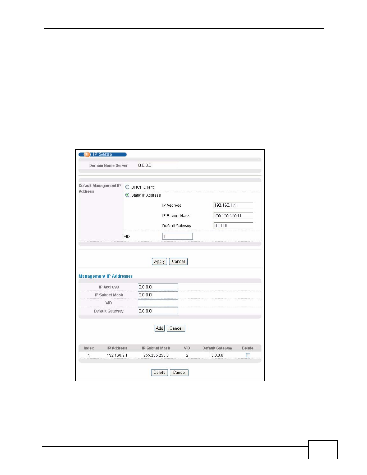
8.6.1 Management IP Addresses
The Switch needs an IP address for it to be managed over the network. The
factory default IP address is 192.168.1.1. The subnet mask specifies the network
number portion of an IP address. The factory default subnet mask is
255.255.255.0.
You can config ure up to 64 IP addresses which are used to access and manage the
Switch from the ports belonging to the pre-defined VLAN(s).
Note: You must configure a VLAN first.
Figure 43 Basic Setting > IP Setup
Chapter 8 Basic Setting
MES-3528 User’s Guide
83
Page 84

Chapter 8 Basic Setting
The following table describes the labels in this screen.
Table 11 Basic Setting > IP Setup
LABEL DESCRIPTION
Domain Name
Server
Default Management IP Address
DHCP Client Select this option if you have a DHCP server that can assign the
Static IP Address Select this option if you don’t have a DHCP server or if you wish to
IP Address Enter the IP address of your Switch in dotted decimal notation for
IP Subnet Mask Enter the IP subnet mask of your Switch in dotted decimal notation
Default Gateway Enter the IP address of the default outgoing gateway in dotted
VID Enter the VLAN identification number associated with the Switch IP
Management IP Addresses
DNS (Domain Name System) is for mapping a domain name to its
corresponding IP address and vice versa. Enter a domain name server
IP address in order to be able to use a domain name instead of an IP
address.
Switch an IP address, subnet mask, a default gateway IP address and
a domain name server IP address automatically.
assign static IP address information to the Switch. You need to fill in
the following fields when you select this option.
example 192.168.1.1.
for example 255.255.255.0.
decimal notation, for example 192.168.1.254.
address. This is the VLAN ID of the CPU and is used for management
only. The default is "1". All ports, by default, are fixed members of
this "management VLAN" in order to manage the device from any
port. If a port is not a member of this VLAN, then users on that port
cannot access the device. To access the Switch make sure the port
that you are connected to is a member of Management VLAN.
You can create up to 64 IP addresses, which are used to access and manage the Switch
from the ports belonging to the pre-defined VLAN(s). You must configure a VLAN first.
IP Address Enter the IP address for managing the Switch by the members of th e
VLAN specified in the VID field below.
IP Subnet Mask Enter the IP subnet mask in dotted decimal notation.
VID Type the VLAN group identification number.
Default Gateway Enter the IP address of the default outgoing gateway in dotted
decimal notation.
Add Click Add to insert the entry to the summary table below and save
your changes to the Switch’s run-time memory. The Switch loses
these changes if it is turned off or loses power, so use the Save link
on the top navigation panel to save your changes to the non-volatile
memory when you are done configuring.
Cancel Click Cancel to reset the fields to your previous configuration.
Index This field displays the index number of the rule. Click an index
number to edit the rule.
IP Address This field displays the IP address.
IP Subnet Mask This field displays the subnet mask.
VID This field displays the ID number of the VLAN group.
84
MES-3528 User’s Guide
Page 85
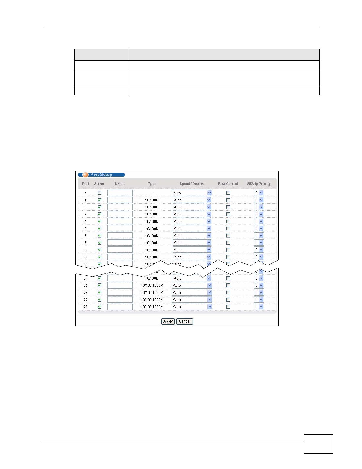
Table 11 Basic Setting > IP Setup (continued)
LABEL DESCRIPTION
Default Gateway This field displays the IP address of the default gateway.
Delete Check the management IP addresses that you want to remove in the
Cancel Click Cancel to clear the selected check boxes in the Delete column.
8.7 Port Setup
Use this screen to configure Switch port settings. Click Basic Setting > Port
Setup in the navigation panel to display the configuration screen.
Figure 44 Basic Setting > Port Setup
Chapter 8 Basic Setting
Delete column, then click the Delete button.
MES-3528 User’s Guide
85
Page 86

Chapter 8 Basic Setting
The following table describes the labels in this screen.
Table 12 Basic Setting > Port Setup
LABEL DESCRIPTION
Port This is the port index number.
* Settings in this row apply to all ports.
Active Select this check box to enable a port. The factory default for all ports is
Name Enter a descriptive name that identifies this port. You can enter up to 64
Type This field displays 10/100M for Fast Ethernet connections and 10/100/
Speed/
Duplex
Use this row only if you want to make some settings the same fo r all ports.
Use this row first to set the common settings and then make adjustments
on a port-by-port basis.
Note: Changes in this row are copied to all the ports as soon as you
make them.
enabled. A port must be enabled for data transmission to occur.
alpha-numerical characters.
Note: Due to space limitation, the port name may be truncated in
some web configurator screens.
1000M for Gigabit connections.
Select the speed and the duplex mode of the Ethernet connection on this
port. Choices are Auto, 10M/Half Duplex, 10M/Full Duplex, 100M/
Half Duplex, 100M/Full Duplex and 1000M/Full Duplex (Gigabit
connections only).
Selecting Auto (auto-negotiation) allows one port to negotiate with a peer
port automatically to obtain the connection speed and duplex mode that
both ends support. When auto-negotiation is turned on, a port on the
Switch negotiates with the peer automatically to determine the connection
speed and duplex mode. If the peer port does not support auto-negotiation
or turns off this feature, the Switch determines the connection speed by
detecting the signal on the cable and using half duplex mode. When the
Switch’s auto-negotiation is turned off, a port uses the pre-configured
speed and duplex mode when making a connection, thus requiring you to
make sure that the settings of the peer port are the same in order to
connect.
Flow Control A concentration of traffic on a port decreases port bandwidth and overflows
buffer memory causing packet discards and frame losses. Flow Control is
used to regulate transmission of signals to match the bandwidth of the
receiving port.
The Switch uses IEEE802.3x flow control in full duplex mode and
backpressure flow control in half duplex mode.
IEEE802.3x flow control is used in full duplex mode to send a pause signal
to the sending port, causing it to temporarily stop sending signals when
the receiving port memory buffers fill.
Back Pressure flow control is typically used in half duplex mode to send a
"collision" signal to the sending port (mimicking a state of packet collision)
causing the sending port to temporarily stop sending signals and resend
later. Select Flow Control to enable it.
86
MES-3528 User’s Guide
Page 87
Chapter 8 Basic Setting
Table 12 Basic Setting > Port Setup (continued)
LABEL DESCRIPTION
802.1p
Priority
Apply Click Apply to save your changes to the Switch’s run-time memory. The
Cancel Click Cancel to begin configuring this screen afresh.
This priority value is added to incoming frames without a (802.1p) priority
queue tag. See Priority Queue Assignment in Table 10 on page 81 for
more information.
Switch loses these changes if it is turned off or loses power, so use the
Save link on the top navigation panel to save your changes to the nonvolatile memory when you are done configuring.
MES-3528 User’s Guide
87
Page 88

Chapter 8 Basic Setting
88
MES-3528 User’s Guide
Page 89

PART III
Advanced
VLAN (91)
Static MAC Forward Setup (111)
Filtering (119)
Spanning Tre e Protocol (121)
Bandwidth Control (143)
Broadcast Storm Control (147)
Mirroring (149)
Link Aggregation (151)
Port Authentication (161)
Port Security (165)
Classifier (169)
Policy Rule (175)
Layer 2 Protocol Tunneling (253)
Queuing Method (181)
VLAN Stacking (185)
Multicast (193)
AAA (209)
IP Source Guard (223)
Loop Guard (249)
89
Page 90

90
Page 91

CHAPTER 9
VLAN
The type of screen you see here depends on the VLAN Type you selected in the
Switch Setup screen. This chapter shows you how to configure 802.1Q tagged
and port-based VLANs.
9.1 Introduction to IEEE 802.1Q Tagged VLANs
A tagged VLAN uses an explicit tag (VLAN ID) in the MAC header to identify the
VLAN membership of a frame across bridges - they are not confined to the switch
on which they were created. The VLANs can be created statically by hand or
dynamically through GVRP. The VLAN ID associates a frame with a specific VLAN
and provides the information that switches need to process the frame across the
network. A tagged frame is four bytes longer than an untagged frame and
contains two bytes of TPID (Tag Protocol Identifier , residing within the type/leng th
field of the Ethernet frame) and two bytes of TCI (Tag Control Information, starts
after the source address field of the Ethernet frame).
The CFI (Canonical Format Indicator) is a single-bit flag, always set to zero for
Ethernet switches. If a frame received at an Ethernet port has a CFI set to 1, then
that frame should not be forwarded as it is to an untagged port. The remaining
twelve bits define the VLAN ID, giving a possible maximum number of 4,096
VLANs. Note that user priority and VLAN ID are independent of each other. A
frame with VID (VLAN Identifier) of null (0) is called a pr iority frame, meaning that
only the priority level is significant and the default VID of the ingress port is given
as the VID of the frame. Of the 4096 possible VIDs, a VID of 0 is used to identify
priority frames and value 4095 (FFF) is reserved, so the maximum possible VLAN
configurations are 4,094.
TPID
2 Bytes
User Priority
3 Bits
CFI
1 Bit
VLAN ID
12 bits
9.1.1 Forwarding Tagged and Untagged Frames
Each port on the Switch is capable of passing tagged or untagged frames. To
forward a frame from an 802.1Q VLAN-a ware switch to an 802.1Q VLAN-unaware
MES-3528 User’s Guide
91
Page 92

Chapter 9 VLAN
switch, the Switch first decides where to forward the fr ame and then strips off the
VLAN tag. To forward a frame from an 802.1Q VLAN-unaware switch to an 802.1Q
VLAN-aware switch, the Switch first decides where to forward the frame, and then
inserts a VLAN tag reflecting the ingress port's default VID. The default PVID is
VLAN 1 for all ports, but this can be changed.
A broadcast frame (or a multicast frame for a multicast group that is known by the
system) is duplicated only on ports that are members of the VID (except the
ingress port itself), thus confining the broadcast to a specific domain.
9.2 Automatic VLAN Registration
GARP and GVRP are the protocols used to automatically register VLAN
membership across switches.
9.2.1 GARP
GARP (Generic Attribute Registration Protocol) allows network switches to register
and de-register attribute values with other GARP participants within a bridged
LAN. GARP is a protocol that provides a generic mechanism for protocols that
serve a more specific application, for example, GVRP.
9.2.1.1 GARP Timers
Switches join VLANs by making a declaration. A declaration is made by issuing a
Join message using GARP. Declarations are withdrawn by issuing a Leave
message. A Leave All message terminates all registrations. GARP timers set
declaration timeout values.
9.2.2 GVRP
GVRP (GARP VLAN Registration Protocol) is a registration protocol that defines a
way for switches to register necessary VLAN members on ports across the
network. Enable this function to permit VLAN groups beyond the local Switch.
Please refer to the following table for common IEEE 802.1Q VLAN terminology.
Table 13 IEEE 802.1Q VLAN Terminology
VLAN
PARAMETER
VLAN Type Permanent VLAN This is a static VLAN created manually.
TERM DESCRIPTION
92
Dynamic VLAN This is a VLAN configured by a GVRP registration/
deregistration process.
MES-3528 User’s Guide
Page 93
Chapter 9 VLAN
Table 13 IEEE 802.1Q VLAN Terminology (continued)
VLAN
PARAMETER
VLAN
Administrative
Control
VLAN Tag Control Tagged Ports belonging to the specified VLAN tag all
VLAN Port Port VID This is the VLAN ID assigned to untagged frames
TERM DESCRIPTION
Registration Fixed Fixed registration ports are permanent VLAN
members.
Registration
Forbidden
Normal
Registration
Untagged Ports belonging to the specified VLAN don't tag all
Acceptable Frame
Type
Ingress filtering If set, the Switch discards incoming frames for
Ports with registration forbidden are forbidden to
join the specified VLAN.
Ports dynamically join a VLAN using GVRP.
outgoing frames transmitted.
outgoing frames transmitted.
that this port received.
You may choose to accept both tagged and
untagged incoming frames, just tagged incoming
frames or just untagged incoming frames on a
port.
VLANs that do not have this port as a member
9.3 Port VLAN Trunking
Enable VLAN Trunking on a port to allow frames belonging to unknown VLAN
groups to pass through that port. This is useful if you w ant to set up VL AN groups
on end devices without having to configure the same VLAN groups on
intermediary devices.
Refer to the following figure. Suppose you want to create VLAN groups 1 and 2
(V1 and V2) on devices A and B. Without VLAN Trunking, you must configure
VLAN groups 1 and 2 on all intermediary switches C, D and E; otherwise they will
drop frames with unknown VLAN group tags. However, with VLAN Trunking
enabled on a port(s) in each intermediary switch you only need to create VLAN
groups in the end devices (A and B). C, D and E automatically allow frames with
MES-3528 User’s Guide
93
Page 94

Chapter 9 VLAN
VLAN group tags 1 and 2 (VLAN groups that are unknown to those switches) to
pass through their VLAN trunking port(s).
Figure 45 Port VLAN Trunking
9.4 Select the VLAN Type
Select a VLAN type in the Basic Setting > Switch Setup screen.
Figure 46 Switch Setup > Select VLAN Type
9.5 Static VLAN
Use a static VLAN to decide whether an incoming frame on a port should be
• sent to a VLAN group as normal depending on its VLAN tag.
• sent to a group whether it has a VLAN tag or not.
• blocked from a VLAN group regardless of its VLAN tag.
You can also tag all outgoing frames (that were previously untagged) from a port
with the specified VID.
94
MES-3528 User’s Guide
Page 95

9.5.1 VLAN Status
See Section 9.1 on page 91 for more information on Static VLAN. Click Advanced
Application > VLAN from the navigation panel to display the VLAN Status
screen as shown next.
Figure 47 Advanced Application > VLAN: VLAN Status
Chapter 9 VLAN
The following table describes the labels in this screen.
Table 14 Advanced Application > VLAN: VLAN Status
LABEL DESCRIPTION
VLAN Search
by VID
The Number
of VLAN
The Number
of Search
Results
Index This is the VLAN index number. Click on an index number to view more
VID This is the VLAN identification number that was configured in the Static
Elapsed Time This field shows how long it has been since a normal VLAN was registered
Enter an existing VLAN ID number(s) (separated by a comma) and click
Search to display only the specified VLAN(s) in the list below.
Leave this field blank and click Search to display all VLANs configured on
the Switch.
This is the number of VLANs configured on the Switch.
This is the number of VLANs that match the searching criteria and display
in the list below.
This field displays only when you use the Search button to look for
certain VLANs.
VLAN details.
VLAN screen.
or a static VLAN was set up.
MES-3528 User’s Guide
95
Page 96
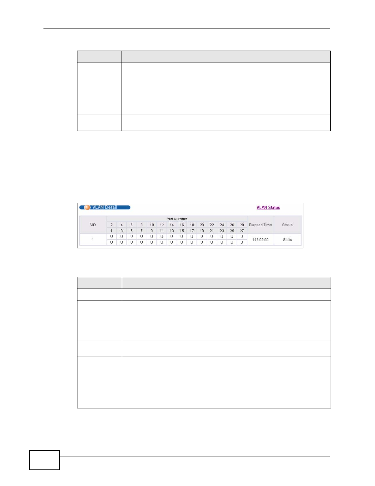
Chapter 9 VLAN
Table 14 Advanced Application > VLAN: VLAN Status (continued)
LABEL DESCRIPTION
Status This field shows how this VLAN was added to the Switch.
dynamic: using GVRP
static: added as a permanent entry
other: added in another way such as via Multicast VLAN Registration
(MVR)
Change Pages Click Previous or Next to show the previous/next screen if all status
information cannot be seen in one screen.
9.5.2 VLAN Details
Use this screen to view detailed port settings and status of the VLAN group. See
Section 9.1 on page 91 for more information on static VLAN. Click on an index
number in the VLAN Status screen to display VLAN details.
Figure 48 Advanced Application > VLAN > VLAN Detail
The following table describes the labels in this screen.
Table 15 Advanced Application > VLAN > VLAN Detail
LABEL DESCRIPTION
VLAN Status Click this to go to the VLAN Status screen.
VID This is the VLAN identification number that was configured in the Static
VLAN screen.
Port Number This column displays the ports that are participating in a VLAN. A tagged
port is marked as T, an untagged port is marked as U and ports not
participating in a VLAN are marked as “–“.
Elapsed Time This field shows how long it has been since a normal VLAN was registered
or a static VLAN was set up.
Status This field shows how this VLAN was added to the Switch.
dynamic: using GVRP
static: added as a permanent entry
other: added in another way such as via Multicast VLAN Registration
(MVR)
96
MES-3528 User’s Guide
Page 97
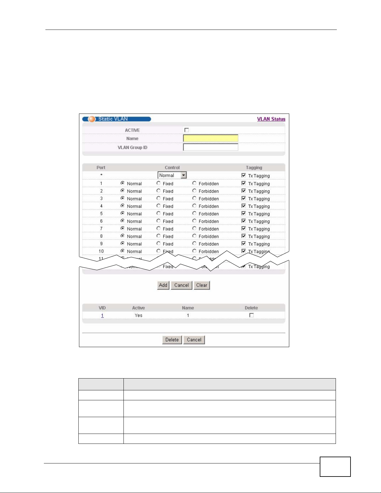
9.5.3 Configure a Static VLAN
Use this screen to configure and view 802.1Q VLAN parameters for the Switch.
See Section 9.1 on page 91 for more information on static VLAN. To configure a
static VLAN, click Static VLAN in the VLAN Status screen to display the screen
as shown next.
Figure 49 Advanced Application > VLAN > Static VLAN
Chapter 9 VLAN
The following table describes the related labels in this screen.
Table 16 Advanced Application > VLAN > Static VLAN
LABEL DESCRIPTION
ACTIVE Select this check box to activate the VLAN settings.
Name Enter a descriptive name for the VLAN group for identification purposes.
VLAN Group IDEnter the VLAN ID for this static entry; the valid range is between 1 and
Port The port number identifies the port you are configuring.
MES-3528 User’s Guide
This name consists of up to 64 printable characters.
4094.
97
Page 98

Chapter 9 VLAN
Table 16 Advanced Application > VLAN > Static VLAN (continued)
LABEL DESCRIPTION
* Settings in this row apply to all ports.
Control Select Normal for the port to dynamically join this VLAN group using
Tagging Select TX Tagging if you want the port to tag all outgoing frames
Add Click Add to save your changes to the Switch’s run-time memory. The
Cancel Click Cancel to change the fields back to their last saved values.
Clear Click Clear to start configuring the screen again.
VID This field displays the ID number of the VLAN group. Click the number to
Active This field indicates whether the VLAN settings are enabled (Yes) or
Name This field displays the descriptive name for this VLAN group.
Delete Click Delete to remove the selected entry from the summary table.
Cancel Click Cancel to clear the Delete check boxes.
Use this row only if you want to make some settings the same for all
ports. Use this row first to set the common settings and then make
adjustments on a port-by-port basis.
Note: Changes in this row are copied to all the ports as soon as you
make them.
GVRP. This is the default selection.
Select Fixed for the port to be a permanent member of this VLAN group.
Select Forbidden if you want to prohibit the port from joining this VLAN
group.
transmitted with this VLAN Group ID.
Switch loses these changes if it is turned off or loses power, so use the
Save link on the top navigation panel to save your changes to the nonvolatile memory when you are done configuring.
edit the VLAN settings.
disabled (No).
98
MES-3528 User’s Guide
Page 99
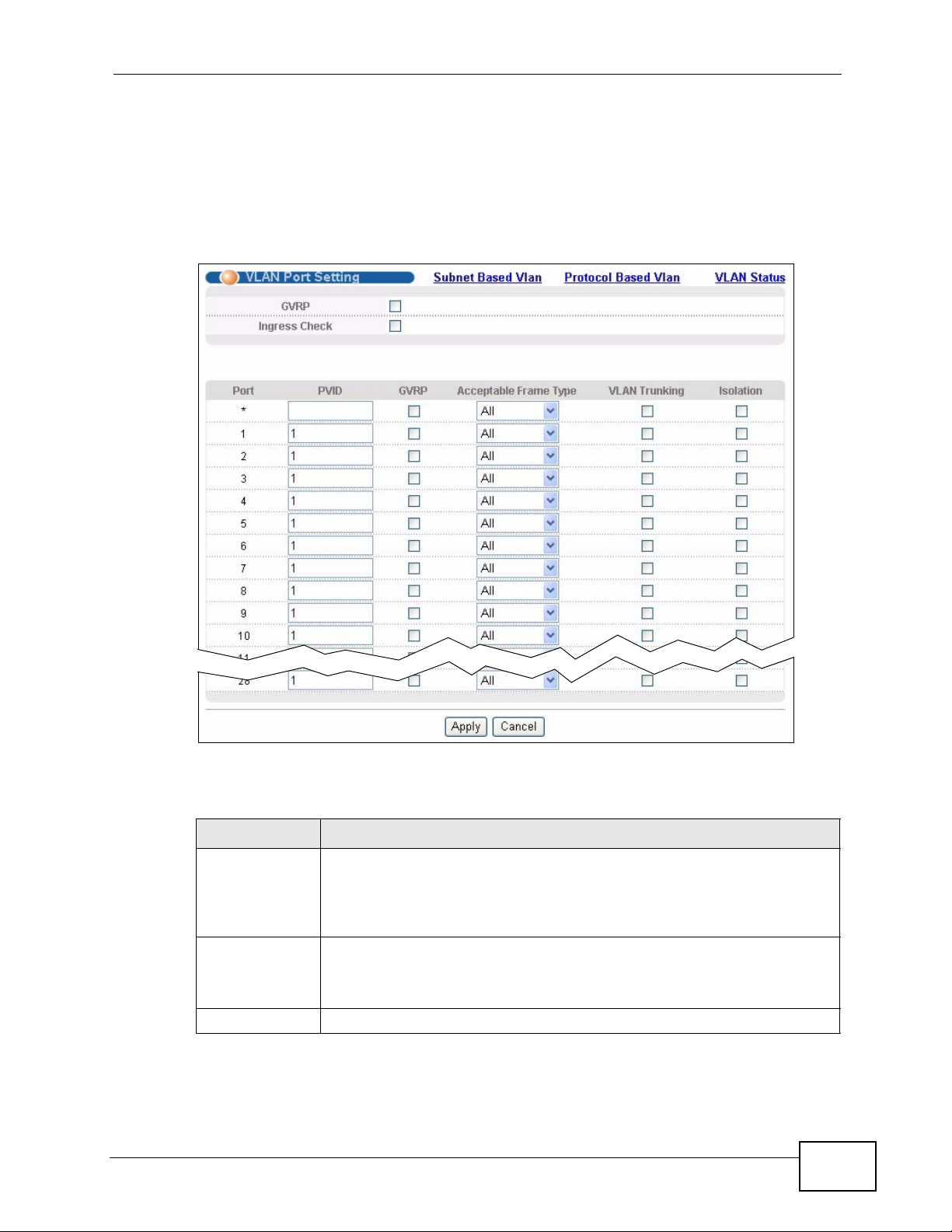
9.5.4 Configure VLAN Port Settings
Use the VLAN Port Setting screen to configure the static VLAN (IEEE 802.1Q)
settings on a port. See Section 9.1 on page 91 for more information on static
VLAN. Click the VLAN Port Setting link in the VLAN Status screen.
Figure 50 Advanced Application > VLAN > VLAN Port Setting
Chapter 9 VLAN
The following table describes the labels in this screen.
Table 17 Advanced Application > VLAN > VLAN Port Setting
LABEL DESCRIPTION
GVRP GVRP (GARP VLAN Registration Protocol) is a registration protocol that
Ingress Check If this check box is selected, the Switch discards incoming frames on a
Port This field displays the port number.
MES-3528 User’s Guide
defines a way for switches to register necessary VLAN members on
ports across the network.
Select this check box to permit VLAN groups beyond the local Switch.
port for VLANs that do not include this port in its member set.
Clear this check box to disable ingress filtering.
99
Page 100

Chapter 9 VLAN
Table 17 Advanced Application > VLAN > VLAN Port Setting (continued)
LABEL DESCRIPTION
* Settings in this row apply to all ports.
PVID A PVID (Port VLAN ID) is a tag that adds to incoming untagged frames
GVRP Select this check box to allow GVRP on this port.
Acceptable
Frame Type
Use this row only if you want to make some settings the same for all
ports. Use this row first to set the common settings and then make
adjustments on a port-by-port basis.
Note: Changes in this row are copied to all the port s as soon as yo u
make them.
received on a port so that the frames are forwarded to the VLAN group
that the tag defines.
Enter a number between 1and 4094 as the port VLAN ID.
Specify the type of frames allowed on a port. Choices are All, Tag O nly
and Untag Only.
Select All from the drop-down list box to accept all untagged or tagged
frames on this port. This is the default setting.
Select Tag Only to accept only tagged frames on this port. All untagged
frames will be dropped.
Select Untag Only to accept only untagged frames on this port. All
tagged frames will be dropped.
VLAN Trunking Enable VLAN Trunking on ports connected to other switches or routers
(but not ports directly connected to end users) to allow frames
belonging to unknown VLAN groups to pass through the Switch.
Isolation Select this to allows this port to communicate only with the CPU
management port and the ports on which the isolation feature is not
enabled.
Apply Click Apply to save y our changes to the Switch’ s run-time memory. The
Switch loses these changes if it is turned off or loses power, so use the
Save link on the top navigation panel to save your changes to the nonvolatile memory when you are done configuring.
Cancel Click Cancel to begin configuring this screen afresh.
9.6 Subnet Based VLANs
Subnet based VLANs allow you to group traffic into logical VLANs based on the
source IP subnet you specify. When a frame is received on a port, the Switch
checks if a tag is added already and the IP subnet it came from. The untagged
packets from the same IP subnet are then pl aced in the same subnet based VLAN.
One advantage of using subnet based VLANs is that priority can be assigned to
traffic from the same IP subnet.
100
MES-3528 User’s Guide
 Loading...