

Chapter 20The UPnP Screen
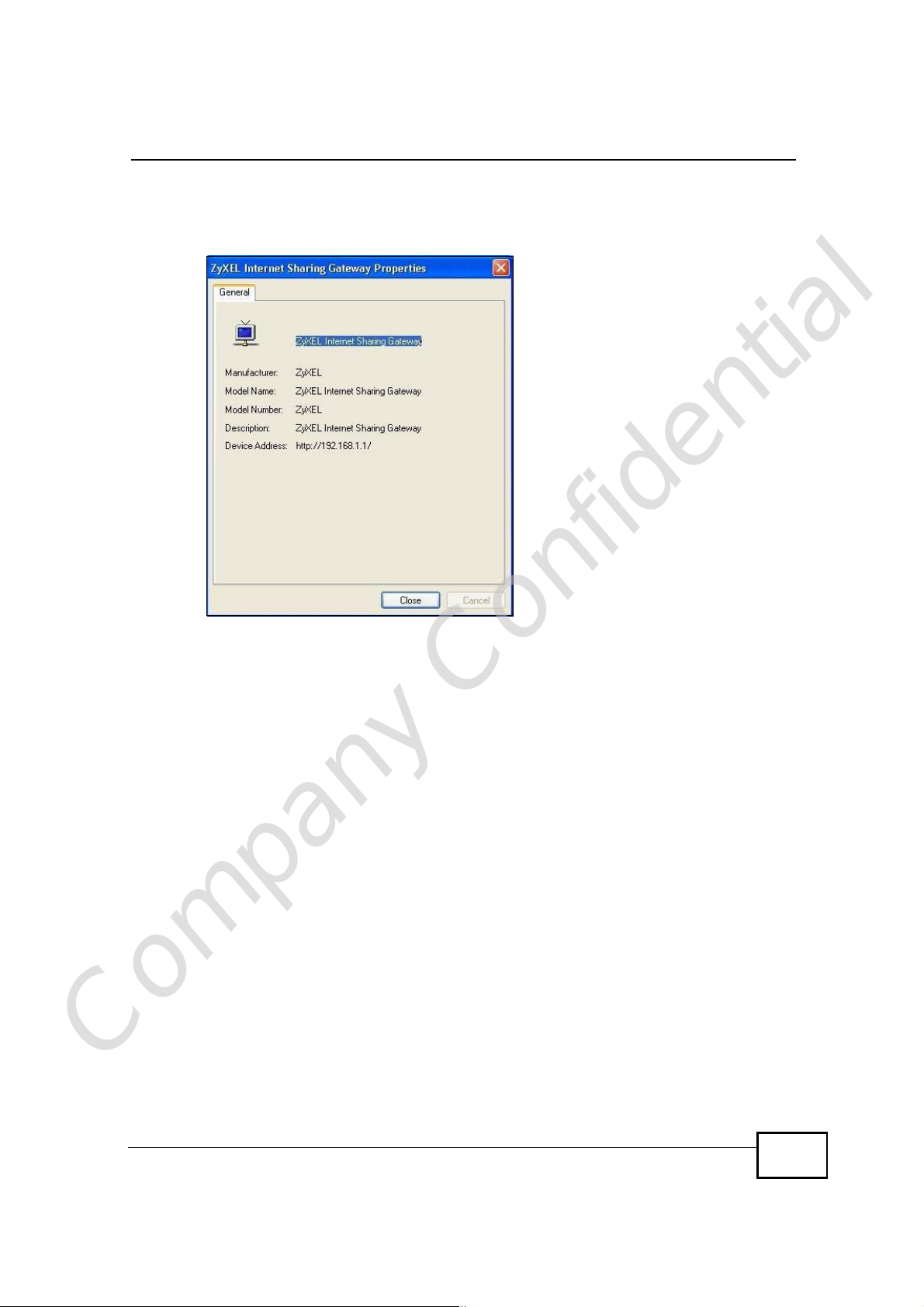
6 Right-click on the icon for your WiMAX Device and select Properties. A properties
window displays with basic information about the WiMAX Device.
Figure 121 Network Connections: My Network Places: Properties: Example
Company Confidential
User’s Guide
251

Chapter 20The UPnP Screen
Company Confidential
252
User’s Guide
CHAPTER 21
The Status Screen
21.1 Overview
Use this screen to view a complete summary of your WiMAX Device connection
status.
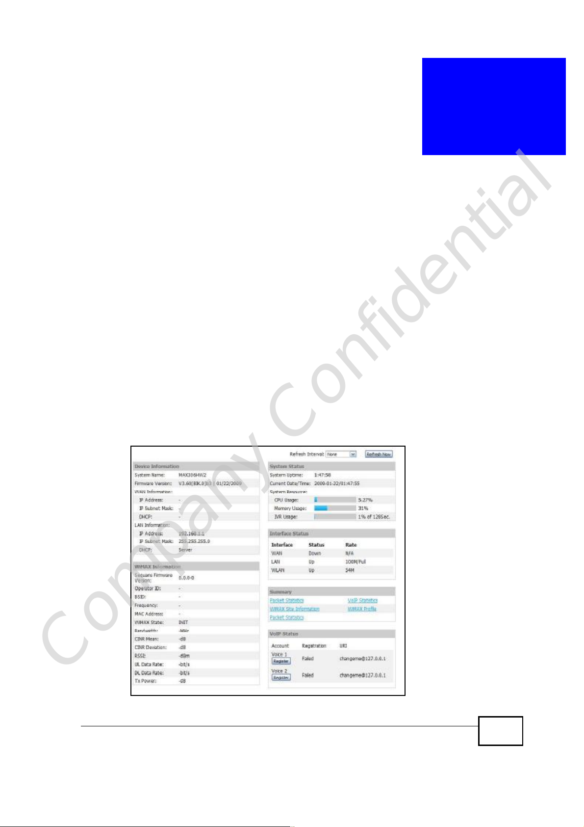
21.2 Status Screen
Click the STATUS icon in the navigation bar to go to this screen, where you can
view the current status of the device, system resources, interfaces (LAN and
WAN), and SIP accounts. You can also register and un-register SIP accounts as
well as view detailed information from DHCP and statistics from WiMAX, VoIP,
bandwidth management, and traffic.
Figure 122 Status
Company Confidential
User’s Guide
253

Chapter 21The Status Screen
The following tables describe the labels in this screen.
Table 113 Status
LABEL DESCRIPTION
Refresh IntervalSelect how often you want the WiMAX Device to update this screen.
Refresh NowClick this to update this screen immediately.
Device Information
System NameThis field displays the WiMAX Device system name. It is used for
Firmware
Version
WAN Information
IP AddressThis field displays the current IP address of the WiMAX Device in the
IP Subnet MaskThis field displays the current subnet mask on the WAN.
DHCPThis field displays what DHCP services the WiMAX Device is using in the
identification.
You can change this in the ADVANCED > System Configuration >
General screen’s System Name field.
This field displays the current version of the firmware inside the device.
It also shows the date the firmware version was created.
You can change the firmware version by uploading new firmware in
ADVANCED > System Configuration > Firmware.
WAN.
WAN. Choices are:
Client - The WiMAX Device is a DHCP client in the WAN. Its IP
address comes from a DHCP server on the WAN.
None - The WiMAX Device is not using any DHCP services in the
WAN. It has a static IP address.
LAN Information
IP AddressThis field displays the current IP address of the WiMAX Device in the
IP Subnet MaskThis field displays the current subnet mask in the LAN.
DHCPThis field displays what DHCP services the WiMAX Device is providing to
WiMAX Information
Operator ID Every WiMAX service provider has a unique Operator ID number, which
BSID This field displays the identification number of the wireless base station
Company Confidential
LAN.
the LAN. Choices are:
Server - The WiMAX Device is a DHCP server in the LAN. It assigns
IP addresses to other computers in the LAN.
Relay - The WiMAX Device is routing DHCP requests to one or more
DHCP servers. The DHCP server(s) may be on another network.
None - The WiMAX Device is not providing any DHCP services to the
LAN.
You can change this in ADVANCED > LAN Configuration > DHCP
Setup.
is broadcast by each base station it owns. You can only connect to the
Internet through base stations belonging to your service provider’s
network.
to which the WiMAX Device is connected. Every base station transmits a
unique BSID, which identifies it across the network.
254
User’s Guide

Chapter 21The Status Screen
Table 113 Status (continued)
LABEL DESCRIPTION
Cell ID A base station’s coverage area can be divided into multiple cells. This
field shows the identification number of the cell in which the WiMAX
Device is connected.
Frequency This field displays the radio frequency of the WiMAX Device’s wireless
connection to a base station.
MAC address This field displays the Media Access Control address of the WiMAX
Device. Every network device has a unique MAC address which
identifies it across the network.
WiMAX StateThis field displays the status of the WiMAX Device’s current connection.
• INIT: the WiMAX Device is starting up.
• DL_SYN: The WiMAX Device is unable to connect to a base station.
• RANGING: the WiMAX Device and the base station are transmitting
and receiving information about the distance between them.
Ranging allows the WiMAX Device to use a lower transmission power
level when communicating with a nearby base station, and a higher
transmission power level when communicating with a distant base
station.
• CAP_NEGO: the WiMAX Device and the base station are exchanging
information about their capabilities.
• AUTH: the WiMAX Device and the base station are exchanging
security information.
• REGIST: the WiMAX Device is registering with a RADIUS server.
• OPERATIONAL: the WiMAX Device has successfully registered with
the base station. Traffic can now flow between the WiMAX Device
and the base station.
• IDLE: the WiMAX Device is in power saving mode, but can connect
when a base station alerts it that there is traffic waiting.
Bandwidth This field shows the size of the bandwidth step the WiMAX Device uses
to connect to a base station in megahertz (MHz).
CINR mean This field shows the average Carrier to Interference plus Noise Ratio of
the current connection. This value is an indication of overall radio signal
quality. A higher value indicates a higher signal quality, and a lower
value indicates a lower signal quality.
CINR deviation This field shows the amount of change in the CINR level. This value is
RSSI This field shows the Received Signal Strength Indication. This value is a
an indication of radio signal stability. A lower number indicates a more
stable signal, and a higher number indicates a less stable signal.
measurement of overall radio signal strength. A higher RSSI level
indicates a stronger signal, and a lower RSSI level indicates a weaker
signal.
A strong signal does not necessarily indicate a good signal: a strong
signal may have a low signal-to-noise ratio (SNR).
UL Data Rate This field shows the number of data packets uploaded from the WiMAX
Device to the base station each second.
DL Data Rate This field shows the number of data packets downloaded to the WiMAX
Device from the base station each second.
PER This field shows the Packet Error Rate. The PER is the percentage of
Company Confidential
User’s Guide
data packets transmitted across the network but not successfully
received.
255

Chapter 21The Status Screen
Table 113 Status (continued)
LABEL DESCRIPTION
Tx Power This field shows the output transmission (Tx) level of the WiMAX
System Status
System UptimeThis field displays how long the WiMAX Device has been running since it
Current Date/
Time
CPU UsageThis field displays what percentage of the WiMAX Device’s processing
Memory UsageThis field displays what percentage of the WiMAX Device’s memory is
IVR UsageThis field displays what percentage of the WiMAX Device’s IVR memory
Interface Status
InterfaceThis column displays each interface of the WiMAX Device.
StatusThis field indicates whether or not the WiMAX Device is using the
Device.
last started up. The WiMAX Device starts up when you plug it in, when
you restart it (ADVANCED > System Configuration > Restart), or
when you reset it.
This field displays the current date and time in the WiMAX Device. You
can change this in SETUP > Time Setting.
ability is currently being used. The higher the CPU usage, the more
likely the WiMAX Device is to slow down. You can reduce this by
disabling some services, such as DHCP, NAT, or content filtering.
currently used. The higher the memory usage, the more likely the
WiMAX Device is to slow down. Some memory is required just to start
the WiMAX Device and to run the web configurator. You can reduce the
memory usage by disabling some services (see CPU Usage); by
reducing the amount of memory allocated to NAT and firewall rules (you
may have to reduce the number of NAT rules or firewall rules to do so);
or by deleting rules in functions such as incoming call policies, speed
dial entries, and static routes.
is currently used. IVR (Interactive Voice Response) refers to the
customizable ring tone and on-hold music you set.
interface.
For the WAN interface, this field displays Up when the WiMAX Device is
connected to a WiMAX network, and Down when the WiMAX Device is
not connected to a WiMAX network.
For the LAN interface, this field displays Up when the WiMAX Device is
using the interface and Down when the WiMAX Device is not using the
interface.
RateFor the LAN ports this displays the port speed and duplex setting.
For the WAN interface, it displays the downstream and upstream
transmission rate or N/A if the WiMAX Device is not connected to a
base station.
For the WLAN interface, it displays the transmission rate when WLAN is
enabled or N/A when WLAN is disabled.
Summary
Packet
Statistics
Company Confidential
WiMAX Site
Information
256
Click this link to view port status and packet specific statistics.
Click this link to view details of the radio frequencies used by the
WiMAX Device to connect to a base station.
User’s Guide

Chapter 21The Status Screen
Table 113 Status (continued)
LABEL DESCRIPTION
DHCP TableClick this link to see details of computers to which the WiMAX Device
has given an IP address.
VoIP StatisticsClick this link to view statistics about your VoIP usage.
WiMAX ProfileClick this link to view details of the current wireless security settings.
VoIP Status
AccountThis column displays each SIP account in the WiMAX Device.
RegistrationThis field displays the current registration status of the SIP account.
You have to register SIP accounts with a SIP server to use VoIP.
If the SIP account is already registered with the SIP server,
Click Unregister to delete the SIP account’s registration in the SIP
server. This does not cancel your SIP account, but it deletes the
mapping between your SIP identity and your IP address or domain
name.
The second field displays Registered.
If the SIP account is not registered with the SIP server,
Click Register to have the WiMAX Device attempt to register the SIP
account with the SIP server.
The second field displays the reason the account is not registered.
Inactive - The SIP account is not active. You can activate it in VOICE
> SIP > SIP Settings.
Register Fail - The last time the WiMAX Device tried to register the SIP
account with the SIP server, the attempt failed. The WiMAX Device
automatically tries to register the SIP account when you turn on the
WiMAX Device or when you activate it.
URIThis field displays the account number and service domain of the SIP
account. You can change these in VOICE > SIP > SIP Settings.
Company Confidential
User’s Guide
257
Chapter 21The Status Screen
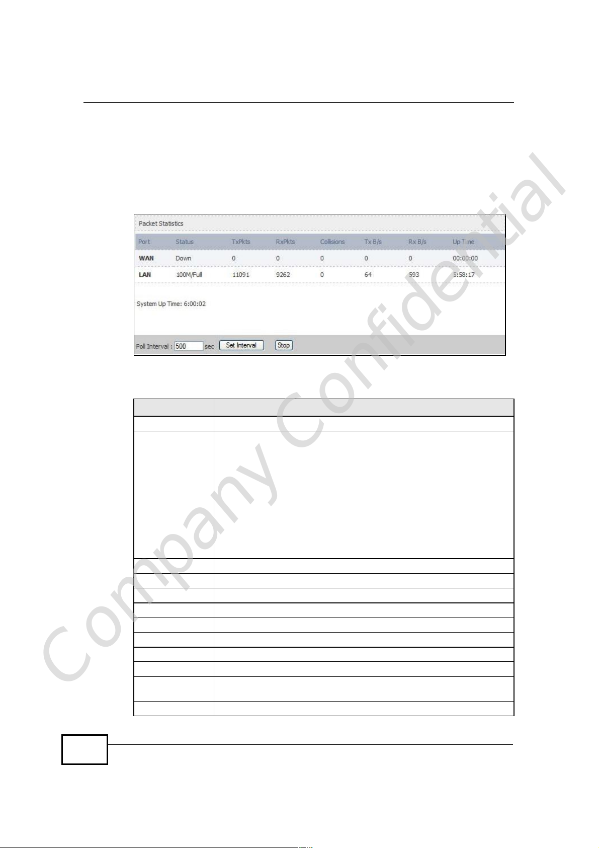
21.2.1 Packet Statistics
Click Status > Packet Statistics to open this screen. This read-only screen
displays information about the data transmission through the WiMAX Device. To
configure these settings, go to the corresponding area in the Advanced screens.
Figure 123 Packet Statistics
The following table describes the fields in this screen.
Table 114 Packet Statistics
LABEL DESCRIPTION
PortThis column displays each interface of the WiMAX Device.
Status This field indicates whether or not the WiMAX Device is using the
TxPkts This field displays the number of packets transmitted on this interface.
RxPkts This field displays the number of packets received on this interface.
Collisions This field displays the number of collisions on this port.
Tx B/s This field displays the number of bytes transmitted in the last second.
Rx B/s This field displays the number of bytes received in the last second.
Up Time This field displays the elapsed time this interface has been connected.
System up Time This is the elapsed time the system has been on.
Poll Interval(s) Type the time interval for the browser to refresh system statistics.
Company Confidential
Set Interval Click this button to apply the new poll interval you entered in the Poll
Stop Click this button to halt the refreshing of the system statistics.
interface.
For the WAN interface, this field displays the port speed and duplex
setting when the WiMAX Device is connected to a WiMAX network, and
Down when the WiMAX Device is not connected to a WiMAX network.
For the LAN interface, this field displays the port speed and duplex
setting when the WiMAX Device is using the interface and Down when
the WiMAX Device is not using the interface.
For the WLAN interface, it displays the transmission rate when WLAN
is enabled or Down when WLAN is disabled.
Interval field above.
258
User’s Guide
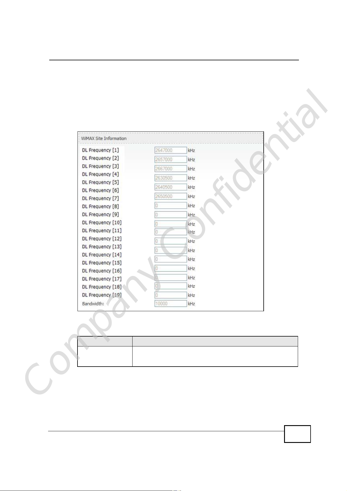
21.2.2 WiMAX Site Information
Click Status > WiMAX Site Information to open this screen. This read-only
screen shows WiMAX frequency information for the WiMAX Device. These settings
can be configured in the ADVANCED > WAN Configuration > WiMAX
Configuration screen.
Figure 124 WiMAX Site Information
Chapter 21The Status Screen
The following table describes the labels in this screen.
Table 115 WiMAX Site Information
LABEL DESCRIPTION
DL Frequency
[0] ~ [19]
These fields show the downlink frequency settings in kilohertz
(kHz). These settings determine how the WiMAX Device searches
for an available wireless connection.
Company Confidential
User’s Guide
259
Chapter 21The Status Screen
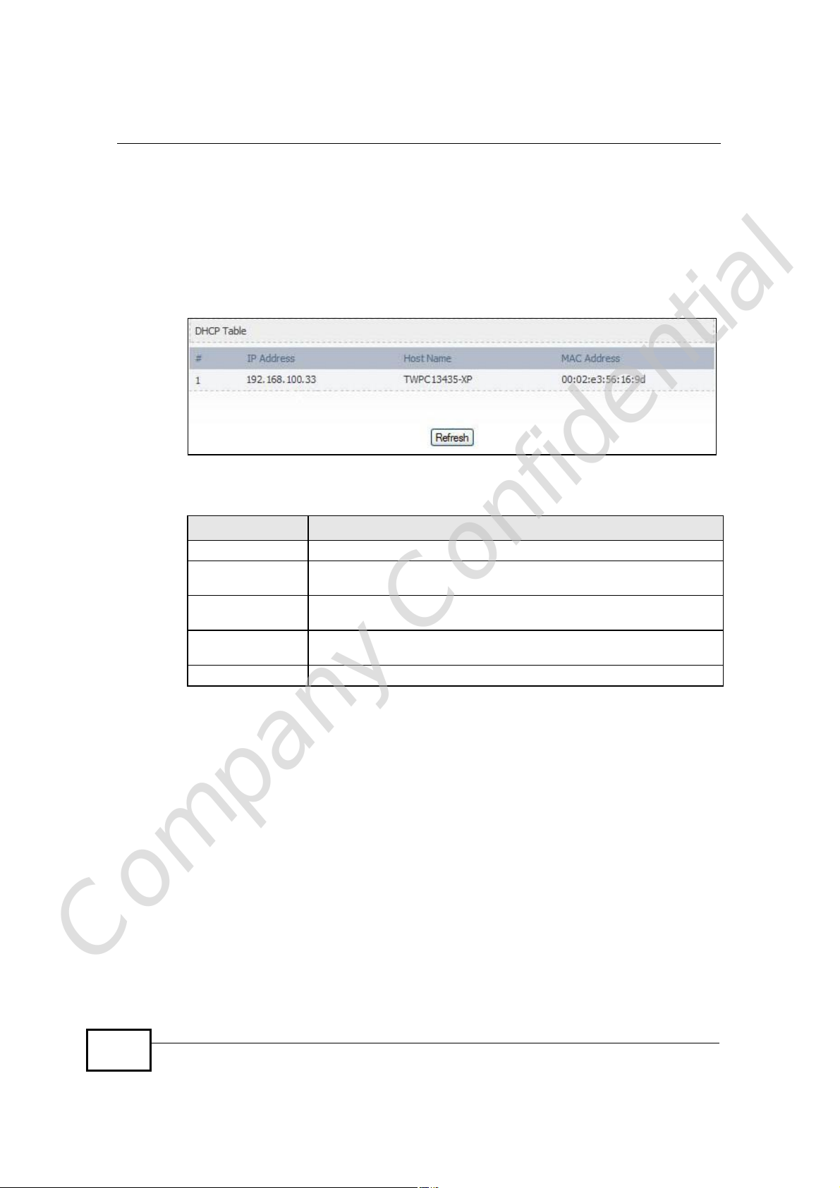
21.2.3 DHCP Table
Click Status > DHCP Table to open this screen. This read-only screen shows the
IP addresses, Host Names and MAC addresses of the devices currently connected
to the WiMAX Device. These settings can be configured in the ADVANCED > LAN
Configuration > DHCP Setup screen.
Figure 125 DHCP Table
Each field is described in the following table.
Table 116 DHCP Table
LABEL DESCRIPTION
#The number of the item in this list.
IP AddressThis field displays the IP address the WiMAX Device assigned to a
Host NameThis field displays the system name of the computer to which the
MAC AddressThis field displays the MAC address of the computer to which the
RefreshClick this button to update the table data.
computer in the network.
WiMAX Device assigned the IP address.
WiMAX Device assigned the IP address.
Company Confidential
260
User’s Guide
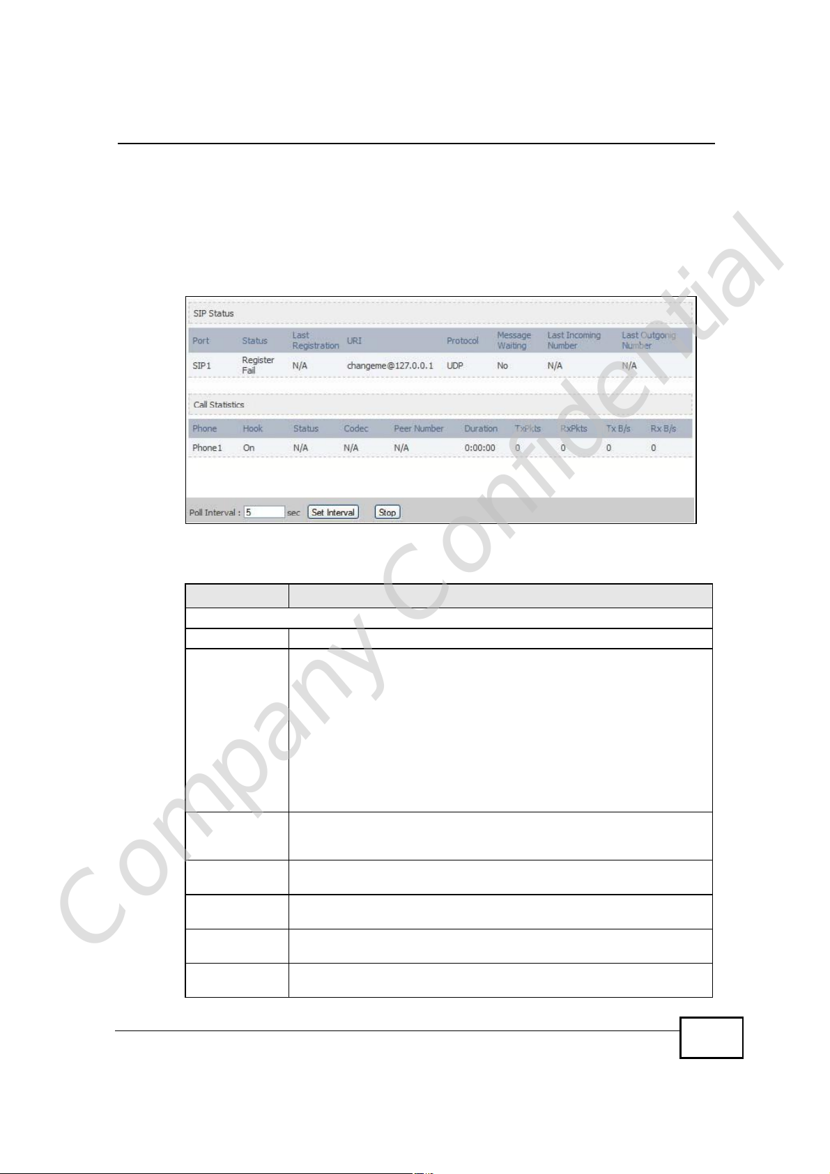
21.2.4 VoIP Statistics
Click Status > DHCP Table to open this screen. This read-only screen shows SIP
registration information, status of calls and VoIP traffic statistics. These settings
can be configured in the VOICE > Service Configuration > SIP Setting screen.
Figure 126 VoIP Statistics
Chapter 21The Status Screen
Each field is described in the following table.
Table 117 VoIP Statistics
LABEL DESCRIPTION
SIP Status
PortThis column displays each SIP account in the WiMAX Device.
StatusThis field displays the current registration status of the SIP account.
You can change this in the Status screen.
Registered - The SIP account is registered with a SIP server.
Register Fail - The last time the WiMAX Device tried to register the SIP
account with the SIP server, the attempt failed. The WiMAX Device
automatically tries to register the SIP account when you turn on the
WiMAX Device or when you activate it.
Inactive - The SIP account is not active. You can activate it in VOICE
> SIP > SIP Settings.
Last
Registration
URIThis field displays the account number and service domain of the SIP
ProtocolThis field displays the transport protocol the SIP account uses. SIP
Message
Company Confidential
Waiting
Last Incoming
Number
This field displays the last time you successfully registered the SIP
account. It displays N/A if you never successfully registered this
account.
account. You can change these in VOICE > SIP > SIP Settings.
accounts always use UDP.
This field indicates whether or not there are any messages waiting for
the SIP account.
This field displays the last number that called the SIP account. It
displays N/A if no number has ever dialed the SIP account.
User’s Guide
261

Chapter 21The Status Screen
Table 117 VoIP Statistics
LABEL DESCRIPTION
Last Outgoing
Number
Call Statistics
PhoneThis field displays the WiMAX Device’s phone port number.
HookThis field indicates whether the phone is on the hook or off the hook.
StatusThis field displays the current state of the phone call.
CodecThis field displays what voice codec is being used for a current VoIP call
Peer NumberThis field displays the SIP number of the party that is currently engaged
DurationThis field displays how long the current call has lasted.
Tx PktsThis field displays the number of packets the WiMAX Device has
Rx PktsThis field displays the number of packets the WiMAX Device has
Tx B/sThis field displays how quickly the WiMAX Device has transmitted
Rx B/sThis field displays how quickly the WiMAX Device has received packets
Poll Interval(s)Enter how often you want the WiMAX Device to update this screen, and
Set IntervalClick this to make the WiMAX Device update the screen based on the
StopClick this to make the WiMAX Device stop updating the screen.
This field displays the last number the SIP account called. It displays
N/A if the SIP account has never dialed a number.
On - The phone is hanging up or already hung up.
Off - The phone is dialing, calling, or connected.
N/A - There are no current VoIP calls, incoming calls or outgoing calls
being made.
DIAL - The callee’s phone is ringing.
RING - The phone is ringing for an incoming VoIP call.
Process - There is a VoIP call in progress.
DISC - The callee’s line is busy, the callee hung up or your phone was
left off the hook.
through a phone port.
in a VoIP call through a phone port.
transmitted in the current call.
received in the current call.
packets in the current call. The rate is the average number of bytes
transmitted per second.
in the current call. The rate is the average number of bytes transmitted
per second.
click Set Interval.
amount of time you specified in Poll Interval.
Company Confidential
262
User’s Guide
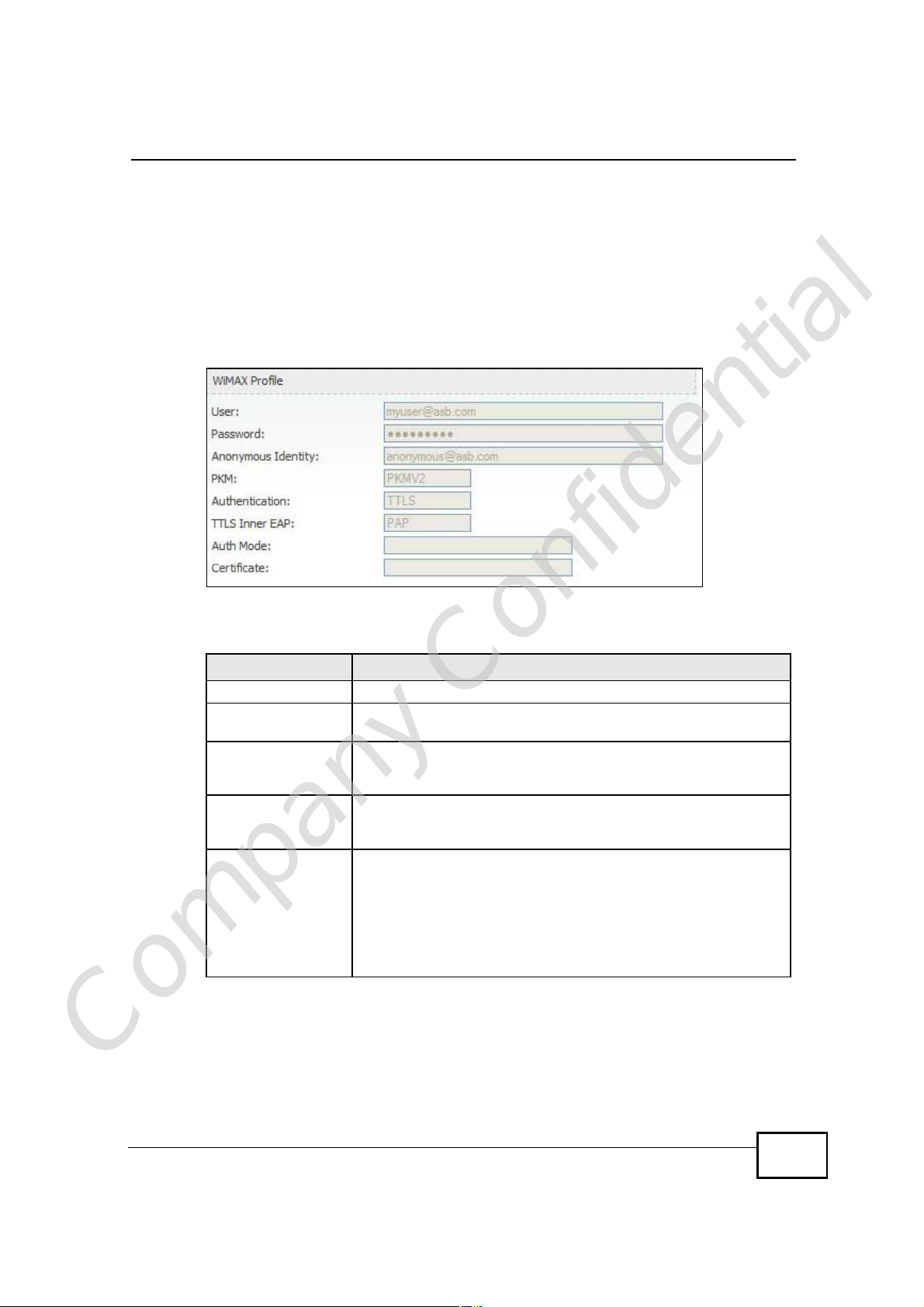
21.2.5 WiMAX Profile
Click Status > WiMAX Profile to open this screen. This read-only screen displays
information about the security settings you are using. To configure these settings,
go to the ADVANCED > WAN Configuration > Internet Connection screen.
Note: Not all WiMAX Device models have all the fields shown here.
Figure 127 WiMAX Profile
Chapter 21The Status Screen
The following table describes the labels in this screen.
Table 118 The WiMAX Profile Screen
LABEL DESCRIPTION
UserThis is the username for your Internet access account.
PasswordThis is the password for your Internet access account. The
password displays as a row of asterisks for security purposes.
Anonymous IdentityThis is the anonymous identity provided by your Internet Service
Provider. Anonymous identity (also known as outer identity) is
used with EAP-TTLS encryption.
PKMThis field displays the Privacy Key Management version number.
PKM provides security between the WiMAX Device and the base
station. See the WiMAX security appendix for more information.
AuthenticationThis field displays the user authentication method. Authentication
is the process of confirming the identity of a user (by means of a
username and password, for example).
EAP-TTLS allows an MS/SS and a base station to establish a
secure link (or ‘tunnel’) with an AAA (Authentication, Authorization
and Accounting) server in order to exchange authentication
information. See the WiMAX security appendix for more details.
Company Confidential
User’s Guide
263

Chapter 21The Status Screen
Table 118 The WiMAX Profile Screen (continued)
LABEL DESCRIPTION
TTLS Inner EAPThis field displays the type of secondary authentication method.
Auth ModeThis is the authentication mode. The WiMAX Device supports the
CertificateThis is the security certificate the WiMAX Device uses to
Once a secure EAP-TTLS connection is established, the inner EAP
is the protocol used to exchange security information between the
mobile station, the base station and the AAA server to
authenticate the mobile station. See the WiMAX security appendix
for more details.
The WiMAX Device supports the following inner authentication
types:
• CHAP (Challenge Handshake Authentication Protocol)
• MSCHAP (Microsoft CHAP)
• MSCHAPV2 (Microsoft CHAP version 2)
• PAP (Password Authentication Protocol)
following authentication modes:
• User Only
• Device Only with Cert
• Certs and User Authentication
authenticate the AAA server, if one is available.
Company Confidential
264
User’s Guide

PART VI
Troubleshooting
and Specifications
Troubleshooting (267)
Product Specifications (275)
Company Confidential
265

Company Confidential
266

CHAPTER 22
Troubleshooting
This chapter offers some suggestions to solve problems you might encounter. The
potential problems are divided into the following categories:
• Power, Hardware Connections, and LEDs
• WiMAX Device Access and Login
• Internet Access
• Phone Calls and VoIP
• Reset the WiMAX Device to Its Factory Defaults
22.1 Power, Hardware Connections, and LEDs
The WiMAX Device does not turn on. None of the LEDs turn on.
1 Make sure you are using the power adapter or cord included with the WiMAX
Device.
2 Make sure the power adapter or cord is connected to the WiMAX Device and
plugged in to an appropriate power source. Make sure the power source is turned
on.
3 Disconnect and re-connect the power adapter or cord to the WiMAX Device.
4 If the problem continues, contact the vendor.
One of the LEDs does not behave as expected.
Company Confidential
1 Make sure you understand the normal behavior of the LED. See Section 1.2.1 on
page 34 for more information.
User’s Guide
267

Chapter 22Troubleshooting
2 Check the hardware connections. See the Quick Start Guide.
3 Inspect your cables for damage. Contact the vendor to replace any damaged
cables.
4 Disconnect and re-connect the power adapter to the WiMAX Device.
5 If the problem continues, contact the vendor.
22.2 WiMAX Device Access and Login
I forgot the IP address for the WiMAX Device.
1 The default IP address is http://192.168.100.1.
2 If you changed the IP address and have forgotten it, you might get the IP address
of the WiMAX Device by looking up the IP address of the default gateway for your
computer. To do this in most Windows computers, click Start > Run, enter cmd,
and then enter ipconfig. The IP address of the Default Gateway might be the IP
address of the WiMAX Device (it depends on the network), so enter this IP address
in your Internet browser.
3 If this does not work, you have to reset the WiMAX Device to its factory defaults.
See Section 22.1 on page 267.
I forgot the password.
1 The default password is 1234.
2 If this does not work, you have to reset the WiMAX Device to its factory defaults.
See Section 11.5 on page 142.
I cannot see or access the Login screen in the web configurator.
Company Confidential
268
1 Make sure you are using the correct IP address.
• The default IP address is http://192.168.100.1.
User’s Guide

Chapter 22Troubleshooting
• If you changed the IP address (Section 5.2 on page 68), use the new IP
address.
• If you changed the IP address and have forgotten it, see the troubleshooting
suggestions for I forgot the IP address for the WiMAX Device.
2 Check the hardware connections, and make sure the LEDs are behaving as
expected. See the Quick Start Guide and Section 1.2.1 on page 34.
3 Make sure your Internet browser does not block pop-up windows and has
JavaScript and Java enabled. See Appendix D on page 327.
4 If there is a DHCP server on your network, make sure your computer is using a
dynamic IP address. Your WiMAX Device is a DHCP server by default.
If there is no DHCP server on your network, make sure your computer’s IP
address is in the same subnet as the WiMAX Device. See Appendix E on page 337.
5 Reset the WiMAX Device to its factory defaults, and try to access the WiMAX
Device with the default IP address. See Section 11.6 on page 143.
6 If the problem continues, contact the network administrator or vendor, or try one
of the advanced suggestions.
Advanced Suggestions
• Try to access the WiMAX Device using another service, such as Telnet. If you
can access the WiMAX Device, check the remote management settings and
firewall rules to find out why the WiMAX Device does not respond to HTTP.
• If your computer is connected wirelessly, use a computer that is connected to a
LAN/ETHERNET port.
I can see the Login screen, but I cannot log in to the WiMAX Device.
1 Make sure you have entered the user name and password correctly. The default
user name is admin, and the default password is 1234. These fields are casesensitive, so make sure [Caps Lock] is not on.
2 You cannot log in to the web configurator while someone is using Telnet to access
the WiMAX Device. Log out of the WiMAX Device in the other session, or ask the
person who is logged in to log out.
3 Disconnect and re-connect the power adapter or cord to the WiMAX Device.
Company Confidential
4 If this does not work, you have to reset the WiMAX Device to its factory defaults.
See Section 11.5 on page 142.
User’s Guide
269

Chapter 22Troubleshooting
I cannot Telnet to the WiMAX Device.
See the troubleshooting suggestions for I cannot see or access the Login screen in
the web configurator. Ignore the suggestions about your browser.
22.3 Internet Access
I cannot access the Internet.
1 Check the hardware connections, and make sure the LEDs are behaving as
expected. See the Quick Start Guide and Section 1.2.1 on page 34.
2 Make sure you entered your ISP account information correctly in the wizard.
These fields are case-sensitive, so make sure [Caps Lock] is not on.
3 Check your security settings. In the web configurator, go to the Status screen.
Click the WiMAX Profile link in the Summary box and make sure that you are
using the correct security settings for your Internet account.
4 Check your WiMAX settings. The WiMAX Device may have been set to search the
wrong frequencies for a wireless connection. In the web configurator, go to the
Status screen. Click the WiMAX Site Information link in the Summary box and
ensure that the values are correct. If the values are incorrect, enter the correct
frequency settings in the ADVANCED > WAN Configuration > WiMAX
Configuration screen. If you are unsure of the correct values, contact your
service provider.
5 If you are trying to access the Internet wirelessly, make sure the wireless settings
in the wireless client are the same as the settings in the AP.
6 Disconnect all the cables from your WiMAX Device, and follow the directions in the
Quick Start Guide again.
7 If the problem continues, contact your ISP.
I cannot access the Internet any more. I had access to the Internet (with the
Company Confidential
WiMAX Device), but my Internet connection is not available any more.
270
User’s Guide

Chapter 22Troubleshooting
1 Check the hardware connections, and make sure the LEDs are behaving as
expected. See the Quick Start Guide and Section 1.2.1 on page 34.
2 Disconnect and re-connect the power adapter to the WiMAX Device.
3 If the problem continues, contact your ISP.
The Internet connection is slow or intermittent.
1 The quality of the WiMAX Device’s wireless connection to the base station may be
poor. Poor signal reception may be improved by moving the WiMAX Device away
from thick walls and other obstructions, or to a higher floor in your building.
2 There may be radio interference caused by nearby electrical devices such as
microwave ovens and radio transmitters. Move the WiMAX Device away or switch
the other devices off. Weather conditions may also affect signal quality.
3 As well as having an external antenna connector, the MAX-210HW2 is equipped
with an internal directional antenna. If you know the location of the base station,
orient the front of the WiMAX Device (the side with the LEDs) towards the base
station. If you do not know the location of the base station, experiment by moving
the WiMAX Device while observing the Strength Indicator LEDs for an increase
in received signal strength. The MAX-200HW2 and MAX-230HW2 do not have
internal antennas.
4 There might be a lot of traffic on the network. Look at the LEDs, and check Section
1.2.1 on page 34. If the WiMAX Device is sending or receiving a lot of information,
try closing some programs that use the Internet, especially peer-to-peer
applications.
5 Disconnect and re-connect the power adapter to the WiMAX Device.
6 If the problem continues, contact the network administrator or vendor, or try one
of the advanced suggestions.
The Internet connection disconnects.
1 Check your WiMAX link and signal strength using the WiMAX Link and Strength
Indicator LEDs on the device.
Company Confidential
User’s Guide
2 Contact your ISP if the problem persists.
271

Chapter 22Troubleshooting
22.4 Phone Calls and VoIP
The telephone port won’t work or the telephone lacks a dial tone.
1 Check the telephone connections and telephone wire.
2 Make sure you have the VOICE > Service Configuration > SIP Settings
screen properly configured (Chapter 12 on page 147).
I can access the Internet, but cannot make VoIP calls.
1 Make sure you have the VOICE > Service Configuration > SIP Settings
screen properly configured (Chapter 12 on page 147).
2 The VoIP LED should come on. Make sure that your telephone is connected to the
VoIP port (see the Quick Start Guide for information on connecting telephone
cables to the these ports).
3 You can also check the VoIP status in the Status screen.
4 If the VoIP settings are correct, use speed dial to make peer-to-peer calls. If you
cannot make a call using speed dial, there may be something wrong with the SIP
server. Contact your VoIP service provider.
Problems With Multiple SIP Accounts
You can set up two SIP accounts on your WiMAX Device. By default your WiMAX
Device uses SIP account 1 for outgoing calls, and it uses SIP accounts 1 and 2 for
incoming calls. With this setting, you always use SIP account 1 for your outgoing
calls and you cannot distinguish which SIP account the calls are coming in
through. If you want to control the use of different dialing plans for accounting
purposes or other reasons, you need to configure your phone port in order to
control which SIP account you are using when placing or receiving calls.
Company Confidential
272
User’s Guide

Chapter 22Troubleshooting
22.5 Reset the WiMAX Device to Its Factory
Defaults
If you reset the WiMAX Device, you lose all of the changes you have made. The
WiMAX Device re-loads its default settings, and the password resets to 1234. You
have to make all of your changes again.
You will lose all of your changes when you push the Reset button.
To reset the WiMAX Device,
1 Make sure the Power LED is on and not blinking.
2 Press and hold the Reset button for five to ten seconds. Release the Reset button
when the Power LED begins to blink. The default settings have been restored.
If the WiMAX Device restarts automatically, wait for the WiMAX Device to finish
restarting, and log in to the web configurator. The password is “1234”.
If the WiMAX Device does not restart automatically, disconnect and reconnect the
WiMAX Device’s power. Then, follow the directions above again.
22.5.1 Pop-up Windows, JavaScripts and Java Permissions
Please see Appendix D on page 327.
Company Confidential
User’s Guide
273

Chapter 22Troubleshooting
Company Confidential
274
User’s Guide

CHAPTER 23
Product Specifications
This chapter gives details about your WiMAX Device’s hardware and firmware
features.
Table 119 IDU Hardware Specifications
FEATUREDESCRIPTION
Device NameMAX-306HW2-IDU
Dimension (W x D x H)216 mm x 164 mm x 52 mm
Weight450 g
Power48V DC, 1.25A
Ethernet Ports4 RJ-45 Ethernet ports
Phone Ports2 RJ-11 phone ports
Power over Ethernet (PoE)Provides Power over Ethernet via PoE port.
Wireless LAN AntennaExternal dipole, 2dBi gain.
Wireless LAN Antenna
Connector
Operation Environmental Temperature: 0oC ~ 45oC
1 R-SMA connector for external wireless LAN antenna
Humidity: 10% ~ 90% RH
Storage Environmental Temperature: -25oC ~ 55oC
Humidity: 10% ~ 95% RH
CertificationSafety
CSA 60950-1-07
EMI & EMS
CE certification & WiMAX Forum Wave II Compliance
Table 120 Indoor Wireless LAN Specification
FEATUREDESCRIPTION
Standard IEEE802.11b/g compliant
Transmit Output Power802.11b: 17 ± 2dBm @11Mbps (Typical 18dBm)
802.11g: 14 ± 2dBm @54Mbps (Typical 15dBm)
Receiver Sensitivity -70dBm @54M, -85dBm @11M
Company Confidential
User’s Guide
275

Chapter 23Product Specifications
Table 121 ODU Hardware Specifications
FEATUREDESCRIPTION
Device NameMAX-306
Dimension (W x D x H)231 mm x 236 mm x 69.6 mm
Weight4 kg including the mount kits
Data/Power PortIDU end: RJ-45 Connector
WiMAX AntennaMAX-306: CROSS- Polarization 12dBi (Built-in Antenna)
Physical Connector1 Vent Connector
Operation Environmental Temperature: -40oC ~ 60oC
Storage Environmental Temperature: -40oC ~ 65oC
CertificationSafety
MAX-316
ODU end: RJ-45 Connector
MAX-316: CROSS- Polarization 14dBi (Built-in Antenna)
Humidity: 10% ~ 90% RH
Humidity: 10% ~ 95% RH
EN60950-1 (CE-LVD & CB by TUV)
EMI & EMS
FCC certification & WiMAX Forum Wave II Compliance
CE certification & WiMAX Forum Wave II Compliance
Other
Water Tightness: IP65
Wind Resistance Testing: Hurricane/Wind Speed
56.1-61.2(m/s)
Table 122 Outdoor Wireless LAN Specification
FEATUREDESCRIPTION
Standard IEEE 802.16e-2005
ModulationQPSK, 16QAM, 64QAM (DL Only)
Duplex modeMTDD
WiMAX BandwidthMAX-306: 2.5-2.7 GHz (5MHz/10MHz)
MAX-316: 3.4-3.6 GHz (5MHz/7MHz/10MHz)
Channel Bandwidth / FFT size5MHz / 512FFT, 7MHz / 1024 FFT and 10MHz / 1024FFT
Sensitivity96dBm @ QPSK 1/2
Data RateAggregate throughput up to 30 Mbps
Maximum Output Power at
Antenna Port
26dBm
Company Confidential
276
User’s Guide

PART VII
Appendices and
Index
WiMAX Security (279)
Setting Up Your Computer’s IP Address
(283)
Pop-up Windows, JavaScripts and Java
Permissions (327)
IP Addresses and Subnetting (337)
Importing Certificates (349)
SIP Passthrough (381)
Common Services (383)
Legal Information (387)
Customer Support (391)
Company Confidential
277

Company Confidential
278

APPENDIX A
WiMAX Security
Wireless security is vital to protect your wireless communications. Without it,
information transmitted over the wireless network would be accessible to any
networking device within range.
User Authentication and Data Encryption
The WiMAX (IEEE 802.16) standard employs user authentication and encryption to
ensure secured communication at all times.
User authentication is the process of confirming a user’s identity and level of
authorization. Data encryption is the process of encoding information so that it
cannot be read by anyone who does not know the code.
WiMAX uses PKMv2 (Privacy Key Management version 2) for authentication, and
CCMP (Counter Mode with Cipher Block Chaining Message Authentication Protocol)
for data encryption.
WiMAX supports EAP (Extensible Authentication Protocol, RFC 2486) which allows
additional authentication methods to be deployed with no changes to the base
station or the mobile or subscriber stations.
PKMv2
PKMv2 is a procedure that allows authentication of a mobile or subscriber station
and negotiation of a public key to encrypt traffic between the MS/SS and the base
station. PKMv2 uses standard EAP methods such as Transport Layer Security
(EAP-TLS) or Tunneled TLS (EAP-TTLS) for secure communication.
In cryptography, a ‘key’ is a piece of information, typically a string of random
numbers and letters, that can be used to ‘lock’ (encrypt) or ‘unlock’ (decrypt) a
message. Public key encryption uses key pairs, which consist of a public (freely
available) key and a private (secret) key. The public key is used for encryption
and the private key is used for decryption. You can decrypt a message only if you
Company Confidential
have the private key. Public key certificates (or ‘digital IDs’) allow users to verify
each other’s identity.
User’s Guide
279

Appendix AWiMAX Security
RADIUS
RADIUS is based on a client-server model that supports authentication,
authorization and accounting. The base station is the client and the server is the
RADIUS server. The RADIUS server handles the following tasks:
• Authentication
Determines the identity of the users.
• Authorization
Determines the network services available to authenticated users once they are
connected to the network.
• Accounting
Keeps track of the client’s network activity.
RADIUS is a simple package exchange in which your base station acts as a
message relay between the MS/SS and the network RADIUS server.
Types of RADIUS Messages
The following types of RADIUS messages are exchanged between the base station
and the RADIUS server for user authentication:
• Access-Request
Sent by an base station requesting authentication.
• Access-Reject
Sent by a RADIUS server rejecting access.
• Access-Accept
Sent by a RADIUS server allowing access.
• Access-Challenge
Sent by a RADIUS server requesting more information in order to allow access.
The base station sends a proper response from the user and then sends another
Access-Request message.
The following types of RADIUS messages are exchanged between the base station
and the RADIUS server for user accounting:
• Accounting-Request
Sent by the base station requesting accounting.
• Accounting-Response
Sent by the RADIUS server to indicate that it has started or stopped accounting.
Company Confidential
In order to ensure network security, the access point and the RADIUS server use a
shared secret key, which is a password they both know. The key is not sent over
280
User’s Guide

the network. In addition to the shared key, password information exchanged is
also encrypted to protect the network from unauthorized access.
Diameter
Diameter (RFC 3588) is a type of AAA server that provides several improvements
over RADIUS in efficiency, security, and support for roaming.
Security Association
The set of information about user authentication and data encryption between two
computers is known as a security association (SA). In a WiMAX network, the
process of security association has three stages.
• Authorization request and reply
The MS/SS presents its public certificate to the base station. The base station
verifies the certificate and sends an authentication key (AK) to the MS/SS.
• Key request and reply
The MS/SS requests a transport encryption key (TEK) which the base station
generates and encrypts using the authentication key.
• Encrypted traffic
The MS/SS decrypts the TEK (using the authentication key). Both stations can
now securely encrypt and decrypt the data flow.
Appendix AWiMAX Security
CCMP
All traffic in a WiMAX network is encrypted using CCMP (Counter Mode with Cipher
Block Chaining Message Authentication Protocol). CCMP is based on the 128-bit
Advanced Encryption Standard (AES) algorithm.
‘Counter mode’ refers to the encryption of each block of plain text with an
arbitrary number, known as the counter. This number changes each time a block
of plain text is encrypted. Counter mode avoids the security weakness of repeated
identical blocks of encrypted text that makes encrypted data vulnerable to
pattern-spotting.
‘Cipher Block Chaining Message Authentication’ (also known as CBC-MAC) ensures
message integrity by encrypting each block of plain text in such a way that its
encryption is dependent on the block before it. This series of ‘chained’ blocks
creates a message authentication code (MAC or CMAC) that ensures the encrypted
data has not been tampered with.
Company Confidential
User’s Guide
281

Appendix AWiMAX Security
Authentication
The WiMAX Device supports EAP-TTLS authentication.
EAP-TTLS (Tunneled Transport Layer Service)
EAP-TTLS is an extension of the EAP-TLS authentication that uses certificates for
only the server-side authentications to establish a secure connection (with EAPTLS digital certifications are needed by both the server and the wireless clients for
mutual authentication). Client authentication is then done by sending username
and password through the secure connection, thus client identity is protected. For
client authentication, EAP-TTLS supports EAP methods and legacy authentication
methods such as PAP, CHAP, MS-CHAP and MS-CHAP v2.
Company Confidential
282
User’s Guide

APPENDIX B
Setting Up Your Computer’s IP
Address
Note: Your specific ZyXEL device may not support all of the operating systems
described in this appendix. See the product specifications for more information
about which operating systems are supported.
This appendix shows you how to configure the IP settings on your computer in
order for it to be able to communicate with the other devices on your network.
Windows Vista/XP/2000, Mac OS 9/OS X, and all versions of UNIX/LINUX include
the software components you need to use TCP/IP on your computer.
If you manually assign IP information instead of using a dynamic IP, make sure
that your network’s computers have IP addresses that place them in the same
subnet.
In this appendix, you can set up an IP address for:
• Windows XP/NT/2000 on page284
• Windows Vista on page287
• Mac OS X: 10.3 and 10.4 on page291
• Mac OS X: 10.5 on page295
• Linux: Ubuntu 8 (GNOME) on page 298
• Linux: openSUSE 10.3 (KDE) on page304
Company Confidential
User’s Guide
283

Appendix BSetting Up Your Computer’s IP Address
Windows XP/NT/2000
The following example uses the default Windows XP display theme but can also
apply to Windows 2000 and Windows NT.
1 Click Start > Control Panel.
Figure 128 Windows XP: Start Menu
2 In the Control Panel, click the Network Connections icon.
Figure 129 Windows XP: Control Panel
Company Confidential
284
User’s Guide

Appendix BSetting Up Your Computer’s IP Address
3 Right-click Local Area Connection and then select Properties.
Figure 130 Windows XP: Control Panel > Network Connections > Properties
4 On the General tab, select Internet Protocol (TCP/IP) and then click
Properties.
Figure 131 Windows XP: Local Area Connection Properties
Company Confidential
User’s Guide
285

Appendix BSetting Up Your Computer’s IP Address
5 The Internet Protocol TCP/IP Properties window opens.
Figure 132 Windows XP: Internet Protocol (TCP/IP) Properties
6 Select Obtain an IP address automatically if your network administrator or ISP
assigns your IP address dynamically.
Select Use the following IP Address and fill in the IP address, Subnet mask,
and Default gateway fields if you have a static IP address that was assigned to
you by your network administrator or ISP. You may also have to enter a
Preferred DNS server and an AlternateDNS server, if that information was
provided.
7 Click OK to close the Internet Protocol (TCP/IP) Properties window.
Click OK to close the Local Area Connection Properties window.Verifying Settings
1 Click Start > All Programs > Accessories > Command Prompt.
2 In the Command Prompt window, type "ipconfig" and then press [ENTER].
Company Confidential
286
You can also go to Start > Control Panel > Network Connections, right-click a
network connection, click Status and then click the Support tab to view your IP
address and connection information.
User’s Guide

Windows Vista
This section shows screens from Windows Vista Professional.
1 Click Start > Control Panel.
Figure 133 Windows Vista: Start Menu
2 In the Control Panel, click the Network and Internet icon.
Figure 134 Windows Vista: Control Panel
Appendix BSetting Up Your Computer’s IP Address
3 Click the Network and Sharing Center icon.
Figure 135 Windows Vista: Network And Internet
Company Confidential
User’s Guide
287

Appendix BSetting Up Your Computer’s IP Address
4 Click Manage network connections.
Figure 136 Windows Vista: Network and Sharing Center
5 Right-click Local Area Connection and then select Properties.
Figure 137 Windows Vista: Network and Sharing Center
Note: During this procedure, click Continue whenever Windows displays a screen
saying that it needs your permission to continue.
Company Confidential
288
User’s Guide

Appendix BSetting Up Your Computer’s IP Address
6 Select Internet Protocol Version 4 (TCP/IPv4) and then select Properties.
Figure 138 Windows Vista: Local Area Connection Properties
Company Confidential
User’s Guide
289

Appendix BSetting Up Your Computer’s IP Address
7 The Internet Protocol Version 4 (TCP/IPv4) Properties window opens.
Figure 139 Windows Vista: Internet Protocol Version 4 (TCP/IPv4) Properties
8 Select Obtain an IP address automatically if your network administrator or ISP
assigns your IP address dynamically.
Select Use the following IP Address and fill in the IP address, Subnet mask,
and Default gateway fields if you have a static IP address that was assigned to
you by your network administrator or ISP. You may also have to enter a
Preferred DNS server and an AlternateDNS server, if that information was
provided.Click Advanced.
9 Click OK to close the Internet Protocol (TCP/IP) Properties window.
Click OK to close the Local Area Connection Properties window.Verifying Settings
1 Click Start > All Programs > Accessories > Command Prompt.
2 In the Command Prompt window, type "ipconfig" and then press [ENTER].
Company Confidential
290
You can also go to Start > Control Panel > Network Connections, right-click a
network connection, click Status and then click the Support tab to view your IP
address and connection information.
User’s Guide
Mac OS X: 10.3 and 10.4
The screens in this section are from Mac OS X 10.4 but can also apply to 10.3.
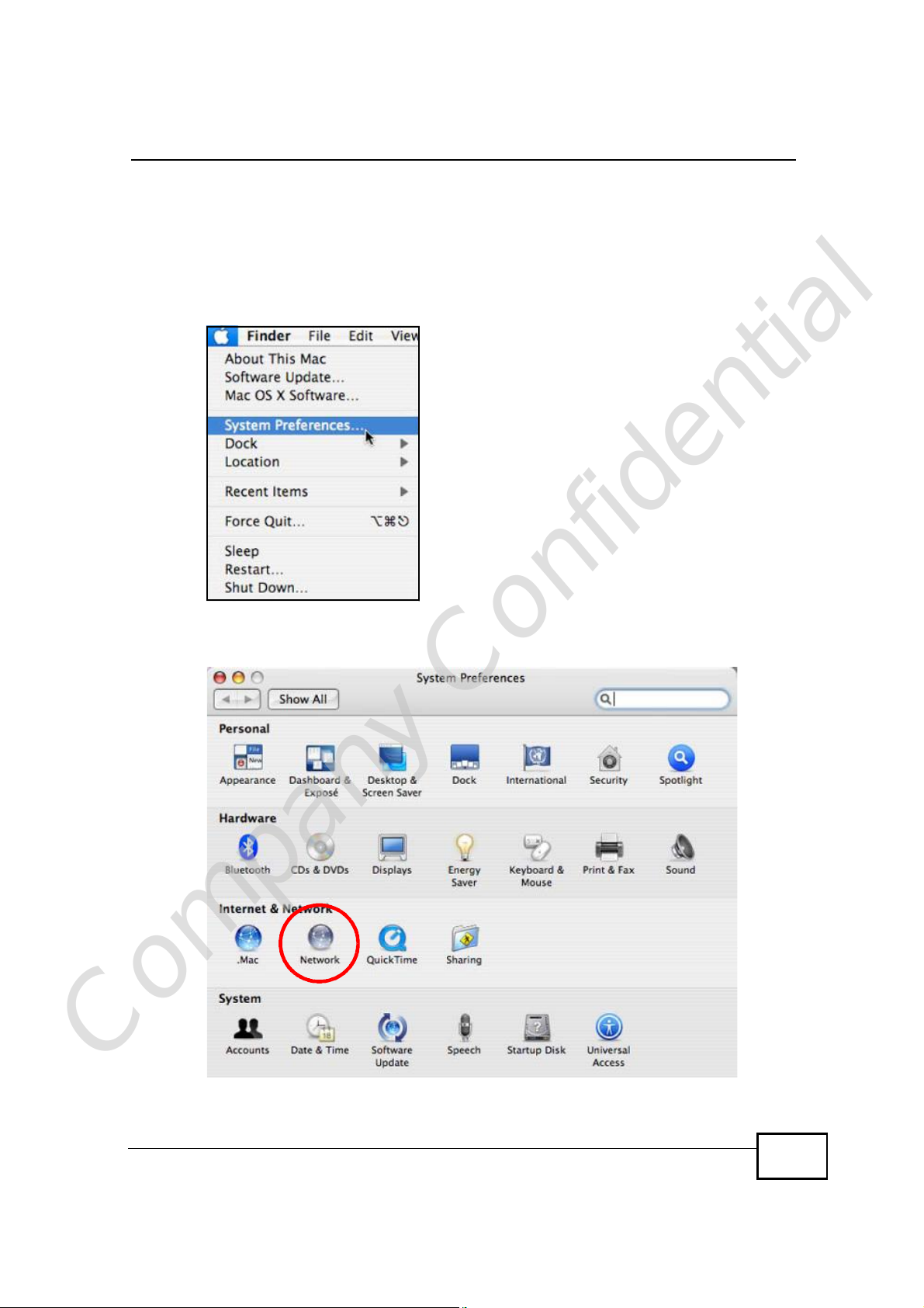
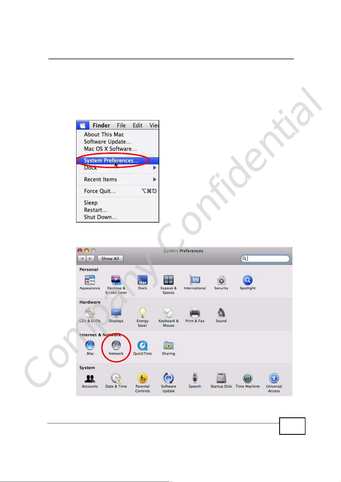
1 Click Apple > System Preferences.
Figure 140 Mac OS X 10.4: Apple Menu
Appendix BSetting Up Your Computer’s IP Address
2 In the System Preferences window, click the Network icon.
Figure 141 Mac OS X 10.4: System Preferences
Company Confidential
User’s Guide
291

Appendix BSetting Up Your Computer’s IP Address
3 When the Network preferences pane opens, select Built-in Ethernet from the
network connection type list, and then click Configure.
Figure 142 Mac OS X 10.4: Network Preferences
4 For dynamically assigned settings, select Using DHCP from the Configure IPv4
list in the TCP/IP tab.
Figure 143 Mac OS X 10.4: Network Preferences > TCP/IP Tab.
Company Confidential
292
User’s Guide

Appendix BSetting Up Your Computer’s IP Address
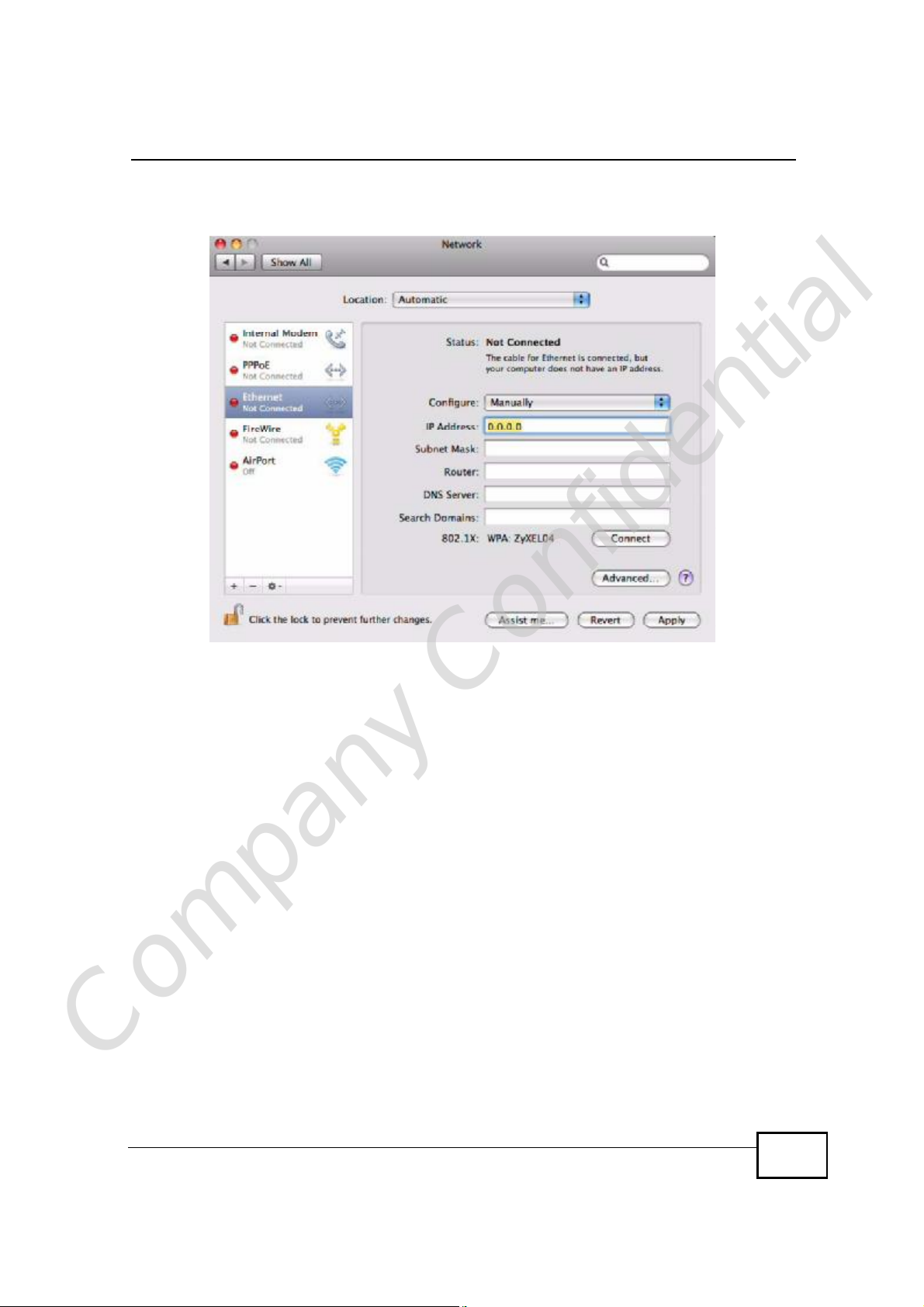
5 For statically assigned settings, do the following:
• From the Configure IPv4 list, select Manually.
• In the IP Address field, type your IP address.
• In the Subnet Mask field, type your subnet mask.
• In the Router field, type the IP address of your device.
Figure 144 Mac OS X 10.4: Network Preferences > Ethernet
Company Confidential
User’s Guide
293

Appendix BSetting Up Your Computer’s IP Address
Click Apply Now and close the window.Verifying Settings
Check your TCP/IP properties by clicking Applications > Utilities > Network
Utilities, and then selecting the appropriate Network Interface from the Info
tab.
Figure 145 Mac OS X 10.4: Network Utility
Company Confidential
294
User’s Guide
Mac OS X: 10.5
The screens in this section are from Mac OS X 10.5.
1 Click Apple > System Preferences.
Figure 146 Mac OS X 10.5: Apple Menu
Appendix BSetting Up Your Computer’s IP Address
2 In System Preferences, click the Network icon.
Figure 147 Mac OS X 10.5: Systems Preferences
Company Confidential
User’s Guide
295

Appendix BSetting Up Your Computer’s IP Address
3 When the Network preferences pane opens, select Ethernet from the list of
available connection types.
Figure 148 Mac OS X 10.5: Network Preferences > Ethernet
4 From the Configure list, select Using DHCP for dynamically assigned settings.
5 For statically assigned settings, do the following:
• From the Configure list, select Manually.
• In the IP Address field, enter your IP address.
• In the Subnet Mask field, enter your subnet mask.
Company Confidential
296
User’s Guide
Appendix BSetting Up Your Computer’s IP Address
• In the Router field, enter the IP address of your WiMAX Device.
Figure 149 Mac OS X 10.5: Network Preferences > Ethernet
6 Click Apply and close the window.
Company Confidential
User’s Guide
297

Appendix BSetting Up Your Computer’s IP Address
Verifying Settings
Check your TCP/IP properties by clicking Applications > Utilities > Network
Utilities, and then selecting the appropriate Network interface from the Info
tab.
Figure 150 Mac OS X 10.5: Network Utility
Linux: Ubuntu 8 (GNOME)
This section shows you how to configure your computer’s TCP/IP settings in the
GNU Object Model Environment (GNOME) using the Ubuntu 8 Linux distribution.
The procedure, screens and file locations may vary depending on your specific
distribution, release version, and individual configuration. The following screens
use the default Ubuntu 8 installation.
Note: Make sure you are logged in as the root administrator.
Follow the steps below to configure your computer IP address in GNOME:
Company Confidential
298
User’s Guide

Appendix BSetting Up Your Computer’s IP Address
1 Click System > Administration > Network.
Figure 151 Ubuntu 8: System > Administration Menu
2 When the Network Settings window opens, click Unlock to open the
Authenticate window. (By default, the Unlock button is greyed out until clicked.)
You cannot make changes to your configuration unless you first enter your admin
password.
Figure 152 Ubuntu 8: Network Settings > Connections
Company Confidential
User’s Guide
299
Appendix BSetting Up Your Computer’s IP Address
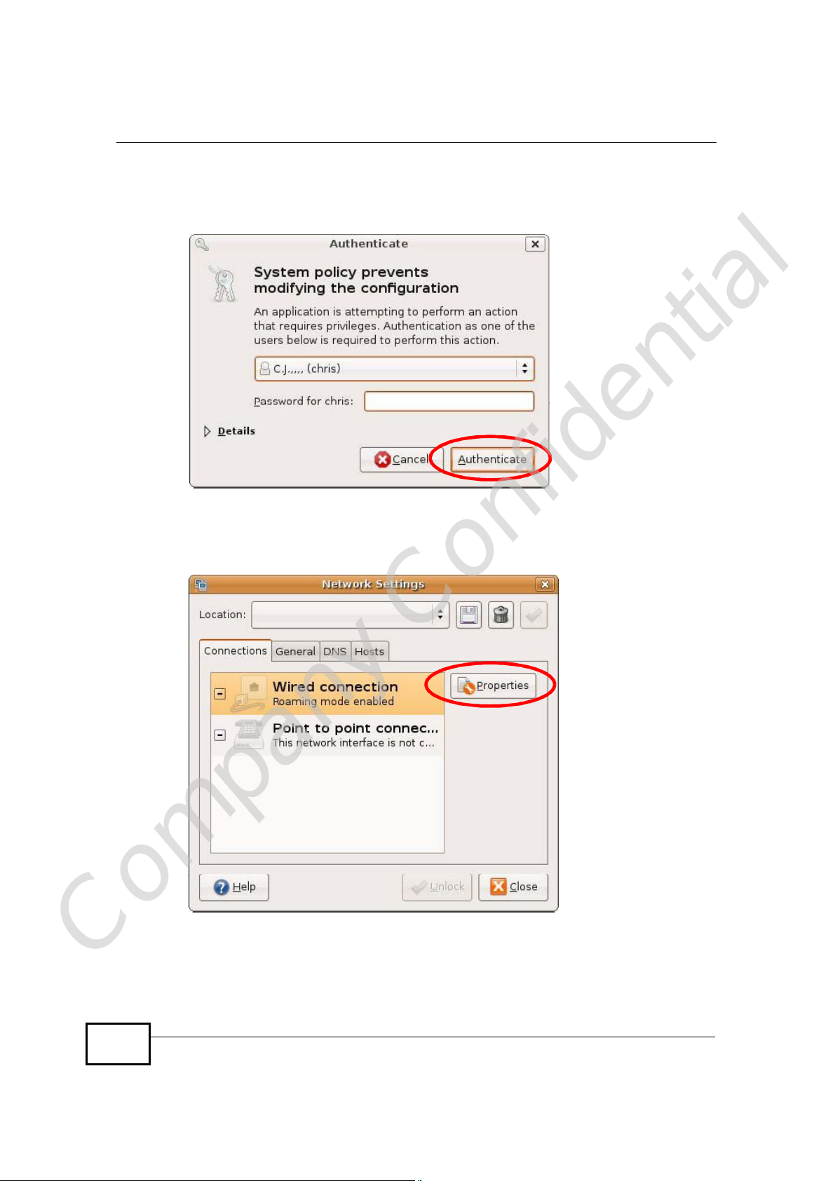
3 In the Authenticate window, enter your admin account name and password then
click the Authenticate button.
Figure 153 Ubuntu 8: Administrator Account Authentication
4 In the Network Settings window, select the connection that you want to
configure, then click Properties.
Figure 154 Ubuntu 8: Network Settings > Connections
Company Confidential
300
User’s Guide

Appendix BSetting Up Your Computer’s IP Address
5 The Properties dialog box opens.
Figure 155 Ubuntu 8: Network Settings > Properties
• In the Configuration list, select Automatic Configuration (DHCP) if you
have a dynamic IP address.
• In the Configuration list, select Static IP address if you have a static IP
address. Fill in the IP address, Subnet mask, and Gateway address fields.
6 Click OK to save the changes and close the Properties dialog box and return to
the Network Settings screen.
Company Confidential
User’s Guide
301

Appendix BSetting Up Your Computer’s IP Address
7 If you know your DNS server IP address(es), click the DNS tab in the Network
Settings window and then enter the DNS server information in the fields
provided.
Figure 156 Ubuntu 8: Network Settings > DNS
8 Click the Close button to apply the changes.
Verifying Settings
Check your TCP/IP properties by clicking System > Administration > Network
Tools, and then selecting the appropriate Network device from the Devices
Company Confidential
302
User’s Guide

Appendix BSetting Up Your Computer’s IP Address
tab. The Interface Statistics column shows data if your connection is working
properly.
Figure 157 Ubuntu 8: Network Tools
Company Confidential
User’s Guide
303

Appendix BSetting Up Your Computer’s IP Address
Linux: openSUSE 10.3 (KDE)
This section shows you how to configure your computer’s TCP/IP settings in the K
Desktop Environment (KDE) using the openSUSE 10.3 Linux distribution. The
procedure, screens and file locations may vary depending on your specific
distribution, release version, and individual configuration. The following screens
use the default openSUSE 10.3 installation.
Note: Make sure you are logged in as the root administrator.
Follow the steps below to configure your computer IP address in the KDE:
1 Click K Menu > Computer > Administrator Settings (YaST).
Figure 158 openSUSE 10.3: K Menu > Computer Menu
Company Confidential
304
User’s Guide
Appendix BSetting Up Your Computer’s IP Address
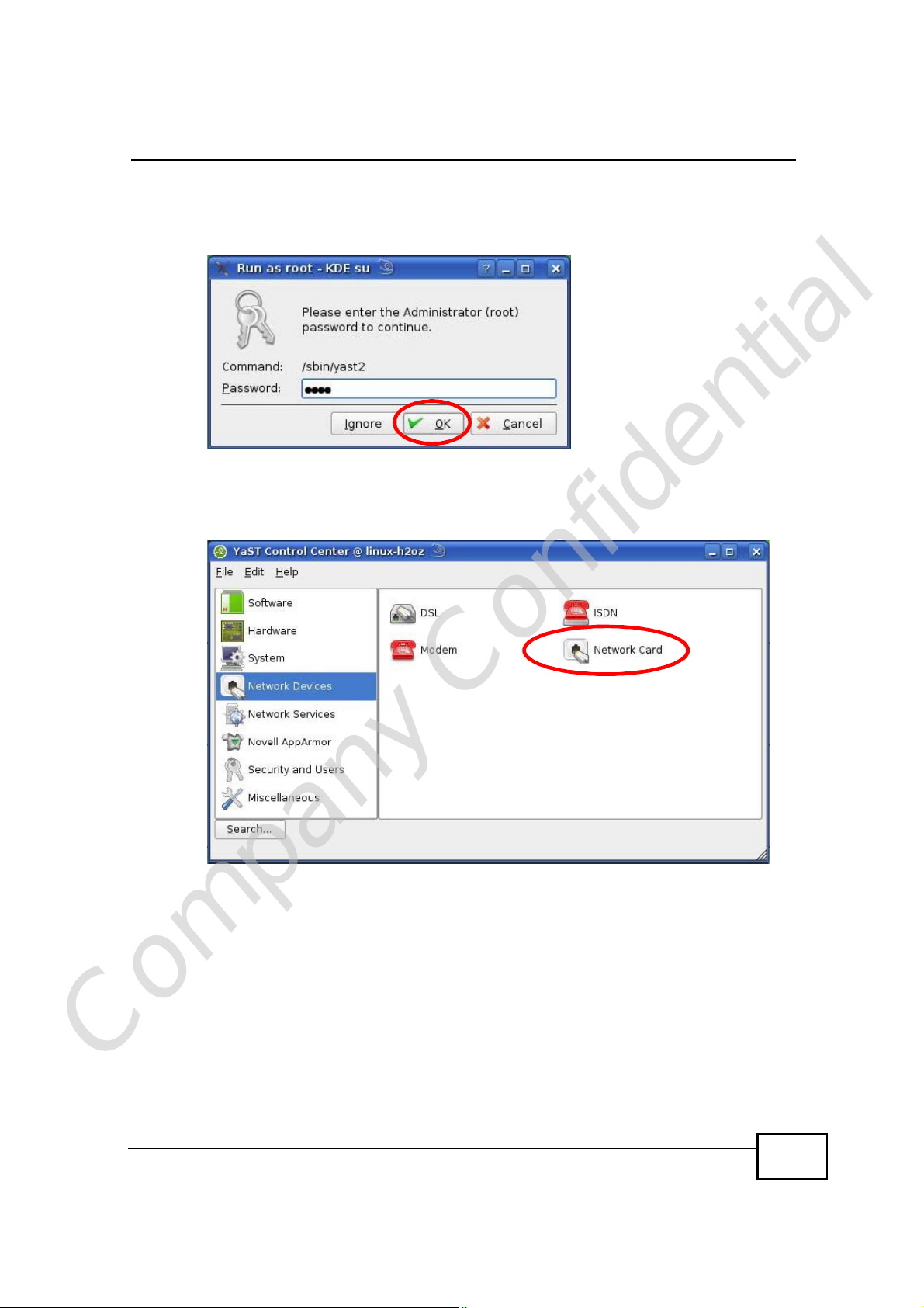
2 When the Run as Root - KDE su dialog opens, enter the admin password and
click OK.
Figure 159 openSUSE 10.3: K Menu > Computer Menu
3 When the YaST Control Center window opens, select Network Devices and
then click the Network Card icon.
Figure 160 openSUSE 10.3: YaST Control Center
Company Confidential
User’s Guide
305

Appendix BSetting Up Your Computer’s IP Address
4 When the Network Settings window opens, click the Overview tab, select the
appropriate connection Name from the list, and then click the Configure button.
Figure 161 openSUSE 10.3: Network Settings
Company Confidential
306
User’s Guide

Appendix BSetting Up Your Computer’s IP Address
5 When the Network Card Setup window opens, click the Address tab
Figure 162 openSUSE 10.3: Network Card Setup
6 Select Dynamic Address (DHCP) if you have a dynamic IP address.
Select Statically assigned IP Address if you have a static IP address. Fill in the
IP address, Subnet mask, and Hostname fields.
7 Click Next to save the changes and close the Network Card Setup window.
Company Confidential
User’s Guide
307

Appendix BSetting Up Your Computer’s IP Address
8 If you know your DNS server IP address(es), click the Hostname/DNS tab in
Network Settings and then enter the DNS server information in the fields
provided.
Figure 163 openSUSE 10.3: Network Settings
9 Click Finish to save your settings and close the window.
Company Confidential
308
User’s Guide

Verifying Settings
Click the KNetwork Manager icon on the Task bar to check your TCP/IP
properties. From the Options sub-menu, select Show Connection Information.
Figure 164 openSUSE 10.3: KNetwork Manager
When the Connection Status - KNetwork Manager window opens, click the
Statistics tab to see if your connection is working properly.
Figure 165 openSUSE: Connection Status - KNetwork Manager
Appendix BSetting Up Your Computer’s IP Address
Company Confidential
User’s Guide
309

Appendix BSetting Up Your Computer’s IP Address
Company Confidential
310
User’s Guide

APPENDIX C
Wireless LANs
Wireless LAN Topologies
This section discusses ad-hoc and infrastructure wireless LAN topologies.
Ad-hoc Wireless LAN Configuration
The simplest WLAN configuration is an independent (Ad-hoc) WLAN that connects
a set of computers with wireless adapters (A, B, C). Any time two or more wireless
adapters are within range of each other, they can set up an independent network,
which is commonly referred to as an ad-hoc network or Independent Basic Service
Set (IBSS). The following diagram shows an example of notebook computers
using wireless adapters to form an ad-hoc wireless LAN.
Figure 166 Peer-to-Peer Communication in an Ad-hoc Network
BSS
A Basic Service Set (BSS) exists when all communications between wireless
clients or between a wireless client and a wired network client go through one
access point (AP).
Intra-BSS traffic is traffic between wireless clients in the BSS. When Intra-BSS is
Company Confidential
User’s Guide
enabled, wireless client A and B can access the wired network and communicate
311

Appendix CWireless LANs
with each other. When Intra-BSS is disabled, wireless client A and B can still
access the wired network but cannot communicate with each other.
Figure 167 Basic Service Set
ESS
An Extended Service Set (ESS) consists of a series of overlapping BSSs, each
containing an access point, with each access point connected together by a wired
network. This wired connection between APs is called a Distribution System (DS).
This type of wireless LAN topology is called an Infrastructure WLAN. The Access
Points not only provide communication with the wired network but also mediate
wireless network traffic in the immediate neighborhood.
Company Confidential
312
User’s Guide

Appendix CWireless LANs
An ESSID (ESS IDentification) uniquely identifies each ESS. All access points and
their associated wireless clients within the same ESS must have the same ESSID
in order to communicate.
Figure 168 Infrastructure WLAN
Channel
A channel is the radio frequency(ies) used by wireless devices to transmit and
receive data. Channels available depend on your geographical area. You may have
a choice of channels (for your region) so you should use a channel different from
an adjacent AP (access point) to reduce interference. Interference occurs when
radio signals from different access points overlap causing interference and
degrading performance.
Adjacent channels partially overlap however. To avoid interference due to overlap,
your AP should be on a channel at least five channels away from a channel that an
adjacent AP is using. For example, if your region has 11 channels and an adjacent
AP is using channel 1, then you need to select a channel between 6 or 11.
RTS/CTS
A hidden node occurs when two stations are within range of the same access
Company Confidential
User’s Guide
point, but are not within range of each other. The following figure illustrates a
hidden node. Both stations (STA) are within range of the access point (AP) or
313

Appendix CWireless LANs
wireless gateway, but out-of-range of each other, so they cannot "hear" each
other, that is they do not know if the channel is currently being used. Therefore,
they are considered hidden from each other.
Figure 169 RTS/CTS
When station A sends data to the AP, it might not know that the station B is
already using the channel. If these two stations send data at the same time,
collisions may occur when both sets of data arrive at the AP at the same time,
resulting in a loss of messages for both stations.
RTS/CTS is designed to prevent collisions due to hidden nodes. An RTS/CTS
defines the biggest size data frame you can send before an RTS (Request To
Send)/CTS (Clear to Send) handshake is invoked.
When a data frame exceeds the RTS/CTS value you set (between 0 to 2432
bytes), the station that wants to transmit this frame must first send an RTS
(Request To Send) message to the AP for permission to send it. The AP then
responds with a CTS (Clear to Send) message to all other stations within its range
to notify them to defer their transmission. It also reserves and confirms with the
requesting station the time frame for the requested transmission.
Stations can send frames smaller than the specified RTS/CTS directly to the AP
without the RTS (Request To Send)/CTS (Clear to Send) handshake.
You should only configure RTS/CTS if the possibility of hidden nodes exists on
your network and the "cost" of resending large frames is more than the extra
network overhead involved in the RTS (Request To Send)/CTS (Clear to Send)
handshake.
If the RTS/CTS value is greater than the Fragmentation Threshold value (see
next), then the RTS (Request To Send)/CTS (Clear to Send) handshake will never
occur as data frames will be fragmented before they reach RTS/CTS size.
Note: Enabling the RTS Threshold causes redundant network overhead that could
negatively affect the throughput performance instead of providing a remedy.
Company Confidential
314
User’s Guide

Fragmentation Threshold
A Fragmentation Threshold is the maximum data fragment size (between 256
and 2432 bytes) that can be sent in the wireless network before the AP will
fragment the packet into smaller data frames.
A large Fragmentation Threshold is recommended for networks not prone to
interference while you should set a smaller threshold for busy networks or
networks that are prone to interference.
If the Fragmentation Threshold value is smaller than the RTS/CTS value (see
previously) you set then the RTS (Request To Send)/CTS (Clear to Send)
handshake will never occur as data frames will be fragmented before they reach
RTS/CTS size.
Preamble Type
Preamble is used to signal that data is coming to the receiver. Short and long refer
to the length of the synchronization field in a packet.
Appendix CWireless LANs
Short preamble increases performance as less time sending preamble means
more time for sending data. All IEEE 802.11 compliant wireless adapters support
long preamble, but not all support short preamble.
Use long preamble if you are unsure what preamble mode other wireless devices
on the network support, and to provide more reliable communications in busy
wireless networks.
Use short preamble if you are sure all wireless devices on the network support it,
and to provide more efficient communications.
Use the dynamic setting to automatically use short preamble when all wireless
devices on the network support it, otherwise the WiMAX Device uses long
preamble.
Note: The wireless devices MUSTuse the same preamble mode in order to
communicate.
IEEE 802.11g Wireless LAN
IEEE 802.11g is fully compatible with the IEEE 802.11b standard. This means an
IEEE 802.11b adapter can interface directly with an IEEE 802.11g access point
Company Confidential
(and vice versa) at 11 Mbps or lower depending on range. IEEE 802.11g has
User’s Guide
315

Appendix CWireless LANs
several intermediate rate steps between the maximum and minimum data rates.
The IEEE 802.11g data rate and modulation are as follows:
Table 123 IEEE 802.11g
DATA RATE
(MBPS)
1DBPSK (Differential Binary Phase Shift Keyed)
2DQPSK (Differential Quadrature Phase Shift Keying)
5.5 / 11CCK (Complementary Code Keying)
6/9/12/18/24/36/
48/54
MODULATION
OFDM (Orthogonal Frequency Division Multiplexing)
Wireless Security Overview
Wireless security is vital to your network to protect wireless communication
between wireless clients, access points and the wired network.
Wireless security methods available on the WiMAX Device are data encryption,
wireless client authentication, restricting access by device MAC address and hiding
the WiMAX Device identity.
The following figure shows the relative effectiveness of these wireless security
methods available on your WiMAX Device.
Table 124 Wireless Security Levels
SECURITY
LEVEL
Least
Secure
Most Secure
Note: You must enable the same wireless security settings on the WiMAX Device and
on all wireless clients that you want to associate with it.
SECURITY TYPE
Unique SSID (Default)
Unique SSID with Hide SSID Enabled
MAC Address Filtering
WEP Encryption
IEEE802.1x EAP with RADIUS Server
Authentication
Wi-Fi Protected Access (WPA)
WPA2
Company Confidential
316
User’s Guide

IEEE 802.1x
In June 2001, the IEEE 802.1x standard was designed to extend the features of
IEEE 802.11 to support extended authentication as well as providing additional
accounting and control features. It is supported by Windows XP and a number of
network devices. Some advantages of IEEE 802.1x are:
• User based identification that allows for roaming.
• Support for RADIUS (Remote Authentication Dial In User Service, RFC 2138,
2139) for centralized user profile and accounting management on a network
RADIUS server.
• Support for EAP (Extensible Authentication Protocol, RFC 2486) that allows
additional authentication methods to be deployed with no changes to the access
point or the wireless clients.
RADIUS
RADIUS is based on a client-server model that supports authentication,
authorization and accounting. The access point is the client and the server is the
RADIUS server. The RADIUS server handles the following tasks:
Appendix CWireless LANs
• Authentication
Determines the identity of the users.
• Authorization
Determines the network services available to authenticated users once they are
connected to the network.
• Accounting
Keeps track of the client’s network activity.
RADIUS is a simple package exchange in which your AP acts as a message relay
between the wireless client and the network RADIUS server.
Types of RADIUS Messages
The following types of RADIUS messages are exchanged between the access point
and the RADIUS server for user authentication:
• Access-Request
Sent by an access point requesting authentication.
• Access-Reject
Sent by a RADIUS server rejecting access.
Company Confidential
• Access-Accept
Sent by a RADIUS server allowing access.
User’s Guide
317

Appendix CWireless LANs
• Access-Challenge
Sent by a RADIUS server requesting more information in order to allow access.
The access point sends a proper response from the user and then sends another
Access-Request message.
The following types of RADIUS messages are exchanged between the access point
and the RADIUS server for user accounting:
• Accounting-Request
Sent by the access point requesting accounting.
• Accounting-Response
Sent by the RADIUS server to indicate that it has started or stopped accounting.
In order to ensure network security, the access point and the RADIUS server use a
shared secret key, which is a password, they both know. The key is not sent over
the network. In addition to the shared key, password information exchanged is
also encrypted to protect the network from unauthorized access.
Types of EAP Authentication
This section discusses some popular authentication types: EAP-MD5, EAP-TLS,
EAP-TTLS, PEAP and LEAP. Your wireless LAN device may not support all
authentication types.
EAP (Extensible Authentication Protocol) is an authentication protocol that runs on
top of the IEEE 802.1x transport mechanism in order to support multiple types of
user authentication. By using EAP to interact with an EAP-compatible RADIUS
server, an access point helps a wireless station and a RADIUS server perform
authentication.
The type of authentication you use depends on the RADIUS server and an
intermediary AP(s) that supports IEEE 802.1x. .
For EAP-TLS authentication type, you must first have a wired connection to the
network and obtain the certificate(s) from a certificate authority (CA). A certificate
(also called digital IDs) can be used to authenticate users and a CA issues
certificates and guarantees the identity of each certificate owner.
EAP-MD5 (Message-Digest Algorithm 5)
MD5 authentication is the simplest one-way authentication method. The
authentication server sends a challenge to the wireless client. The wireless client
‘proves’ that it knows the password by encrypting the password with the challenge
Company Confidential
and sends back the information. Password is not sent in plain text.
318
User’s Guide

However, MD5 authentication has some weaknesses. Since the authentication
server needs to get the plaintext passwords, the passwords must be stored. Thus
someone other than the authentication server may access the password file. In
addition, it is possible to impersonate an authentication server as MD5
authentication method does not perform mutual authentication. Finally, MD5
authentication method does not support data encryption with dynamic session
key. You must configure WEP encryption keys for data encryption.
EAP-TLS (Transport Layer Security)
With EAP-TLS, digital certifications are needed by both the server and the wireless
clients for mutual authentication. The server presents a certificate to the client.
After validating the identity of the server, the client sends a different certificate to
the server. The exchange of certificates is done in the open before a secured
tunnel is created. This makes user identity vulnerable to passive attacks. A digital
certificate is an electronic ID card that authenticates the sender’s identity.
However, to implement EAP-TLS, you need a Certificate Authority (CA) to handle
certificates, which imposes a management overhead.
EAP-TTLS (Tunneled Transport Layer Service)
Appendix CWireless LANs
EAP-TTLS is an extension of the EAP-TLS authentication that uses certificates for
only the server-side authentications to establish a secure connection. Client
authentication is then done by sending username and password through the
secure connection, thus client identity is protected. For client authentication, EAPTTLS supports EAP methods and legacy authentication methods such as PAP,
CHAP, MS-CHAP and MS-CHAP v2.
PEAP (Protected EAP)
Like EAP-TTLS, server-side certificate authentication is used to establish a secure
connection, then use simple username and password methods through the
secured connection to authenticate the clients, thus hiding client identity.
However, PEAP only supports EAP methods, such as EAP-MD5, EAP-MSCHAPv2
and EAP-GTC (EAP-Generic Token Card), for client authentication. EAP-GTC is
implemented only by Cisco.
LEAP
LEAP (Lightweight Extensible Authentication Protocol) is a Cisco implementation of
IEEE 802.1x.
Company Confidential
User’s Guide
319

Appendix CWireless LANs
Dynamic WEP Key Exchange
The AP maps a unique key that is generated with the RADIUS server. This key
expires when the wireless connection times out, disconnects or reauthentication
times out. A new WEP key is generated each time reauthentication is performed.
If this feature is enabled, it is not necessary to configure a default encryption key
in the wireless security configuration screen. You may still configure and store
keys, but they will not be used while dynamic WEP is enabled.
Note: EAP-MD5 cannot be used with Dynamic WEP Key Exchange
For added security, certificate-based authentications (EAP-TLS, EAP-TTLS and
PEAP) use dynamic keys for data encryption. They are often deployed in corporate
environments, but for public deployment, a simple user name and password pair
is more practical. The following table is a comparison of the features of
authentication types.
Table 125 Comparison of EAP Authentication Types
EAP-MD5 EAP-TLS EAP-TTLS PEAP LEAP
Mutual Authentication No Yes Yes Yes Yes
Certificate – Client No Yes Optional Optional No
Certificate – Server No Yes Yes Yes No
Dynamic Key Exchange No Yes Yes Yes Yes
Credential Integrity None Strong Strong Strong Moderate
Deployment Difficulty Easy Hard Moderate Moderate Moderate
Client Identity
Protection
No No Yes Yes No
WPA and WPA2
Wi-Fi Protected Access (WPA) is a subset of the IEEE 802.11i standard. WPA2
(IEEE 802.11i) is a wireless security standard that defines stronger encryption,
authentication and key management than WPA.
Key differences between WPA or WPA2 and WEP are improved data encryption
and user authentication.
If both an AP and the wireless clients support WPA2 and you have an external
RADIUS server, use WPA2 for stronger data encryption. If you don't have an
external RADIUS server, you should use WPA2-PSK (WPA2-Pre-Shared Key) that
only requires a single (identical) password entered into each access point, wireless
Company Confidential
320
gateway and wireless client. As long as the passwords match, a wireless client will
be granted access to a WLAN.
User’s Guide

Encryption
Appendix CWireless LANs
If the AP or the wireless clients do not support WPA2, just use WPA or WPA-PSK
depending on whether you have an external RADIUS server or not.
Select WEP only when the AP and/or wireless clients do not support WPA or WPA2.
WEP is less secure than WPA or WPA2.
WPA improves data encryption by using Temporal Key Integrity Protocol (TKIP),
Message Integrity Check (MIC) and IEEE 802.1x. WPA2 also uses TKIP when
required for compatibility reasons, but offers stronger encryption than TKIP with
Advanced Encryption Standard (AES) in the Counter mode with Cipher block
chaining Message authentication code Protocol (CCMP).
TKIP uses 128-bit keys that are dynamically generated and distributed by the
authentication server. AES (Advanced Encryption Standard) is a block cipher that
uses a 256-bit mathematical algorithm called Rijndael. They both include a perpacket key mixing function, a Message Integrity Check (MIC) named Michael, an
extended initialization vector (IV) with sequencing rules, and a re-keying
mechanism.
WPA and WPA2 regularly change and rotate the encryption keys so that the same
encryption key is never used twice.
The RADIUS server distributes a Pairwise Master Key (PMK) key to the AP that
then sets up a key hierarchy and management system, using the PMK to
dynamically generate unique data encryption keys to encrypt every data packet
that is wirelessly communicated between the AP and the wireless clients. This all
happens in the background automatically.
The Message Integrity Check (MIC) is designed to prevent an attacker from
capturing data packets, altering them and resending them. The MIC provides a
strong mathematical function in which the receiver and the transmitter each
compute and then compare the MIC. If they do not match, it is assumed that the
data has been tampered with and the packet is dropped.
By generating unique data encryption keys for every data packet and by creating
an integrity checking mechanism (MIC), with TKIP and AES it is more difficult to
decrypt data on a Wi-Fi network than WEP and difficult for an intruder to break
into the network.
The encryption mechanisms used for WPA(2) and WPA(2)-PSK are the same. The
only difference between the two is that WPA(2)-PSK uses a simple common
password, instead of user-specific credentials. The common-password approach
Company Confidential
makes WPA(2)-PSK susceptible to brute-force password-guessing attacks but it’s
still an improvement over WEP as it employs a consistent, single, alphanumeric
password to derive a PMK which is used to generate unique temporal encryption
User’s Guide
321

Appendix CWireless LANs
keys. This prevent all wireless devices sharing the same encryption keys. (a
weakness of WEP)
User Authentication
WPA and WPA2 apply IEEE 802.1x and Extensible Authentication Protocol (EAP) to
authenticate wireless clients using an external RADIUS database. WPA2 reduces
the number of key exchange messages from six to four (CCMP 4-way handshake)
and shortens the time required to connect to a network. Other WPA2
authentication features that are different from WPA include key caching and preauthentication. These two features are optional and may not be supported in all
wireless devices.
Key caching allows a wireless client to store the PMK it derived through a
successful authentication with an AP. The wireless client uses the PMK when it
tries to connect to the same AP and does not need to go with the authentication
process again.
Pre-authentication enables fast roaming by allowing the wireless client (already
connecting to an AP) to perform IEEE 802.1x authentication with another AP
before connecting to it.
Wireless Client WPA Supplicants
A wireless client supplicant is the software that runs on an operating system
instructing the wireless client how to use WPA. At the time of writing, the most
widely available supplicant is theWPA patch for Windows XP, Funk Software's
Odyssey client.
The Windows XP patch is a free download that adds WPA capability to Windows
XP's built-in "Zero Configuration" wireless client. However, you must run Windows
XP to use it.
WPA(2) with RADIUS Application Example
To set up WPA(2), you need the IP address of the RADIUS server, its port number
(default is 1812), and the RADIUS shared secret. A WPA(2) application example
with an external RADIUS server looks as follows. "A" is the RADIUS server. "DS" is
the distribution system.
1 The AP passes the wireless client's authentication request to the RADIUS server.
2 The RADIUS server then checks the user's identification against its database and
grants or denies network access accordingly.
Company Confidential
3 A 256-bit Pairwise Master Key (PMK) is derived from the authentication process by
the RADIUS server and the client.
322
User’s Guide

Appendix CWireless LANs
4 The RADIUS server distributes the PMK to the AP. The AP then sets up a key
hierarchy and management system, using the PMK to dynamically generate
unique data encryption keys. The keys are used to encrypt every data packet that
is wirelessly communicated between the AP and the wireless clients.
Figure 170 WPA(2) with RADIUS Application Example
WPA(2)-PSK Application Example
A WPA(2)-PSK application looks as follows.
1 First enter identical passwords into the AP and all wireless clients. The Pre-Shared
Key (PSK) must consist of between 8 and 63 ASCII characters or 64 hexadecimal
characters (including spaces and symbols).
2 The AP checks each wireless client's password and allows it to join the network
only if the password matches.
3 The AP and wireless clients generate a common PMK (Pairwise Master Key). The
key itself is not sent over the network, but is derived from the PSK and the SSID.
Company Confidential
User’s Guide
323

Appendix CWireless LANs
4 The AP and wireless clients use the TKIP or AES encryption process, the PMK and
information exchanged in a handshake to create temporal encryption keys. They
use these keys to encrypt data exchanged between them.
Figure 171 WPA(2)-PSK Authentication
Security Parameters Summary
Refer to this table to see what other security parameters you should configure for
each authentication method or key management protocol type. MAC address
filters are not dependent on how you configure these security features.
Table 126 Wireless Security Relational Matrix
AUTHENTICATION
METHOD/ KEY
MANAGEMENT
PROTOCOL
OpenNoneNoDisable
Open WEP No Enable with Dynamic WEP Key
Shared WEP No Enable with Dynamic WEP Key
WPA TKIP/AES No Enable
WPA-PSK TKIP/AES Yes Disable
WPA2 TKIP/AES No Enable
WPA2-PSK TKIP/AES Yes Disable
ENCRYPTIO
N METHOD
ENTER
MANUAL KEY
Yes Enable without Dynamic WEP
Yes Disable
Yes Enable without Dynamic WEP
Yes Disable
IEEE 802.1X
Enable without Dynamic WEP
Key
Key
Key
Company Confidential
324
User’s Guide

Antenna Overview
An antenna couples RF signals onto air. A transmitter within a wireless device
sends an RF signal to the antenna, which propagates the signal through the air.
The antenna also operates in reverse by capturing RF signals from the air.
Positioning the antennas properly increases the range and coverage area of a
wireless LAN.
Antenna Characteristics
Frequency
An antenna in the frequency of 2.4GHz (IEEE 802.11b and IEEE 802.11g) or 5GHz
(IEEE 802.11a) is needed to communicate efficiently in a wireless LAN
Radiation Pattern
A radiation pattern is a diagram that allows you to visualize the shape of the
antenna’s coverage area.
Appendix CWireless LANs
Antenna Gain
Antenna gain, measured in dB (decibel), is the increase in coverage within the RF
beam width. Higher antenna gain improves the range of the signal for better
communications.
For an indoor site, each 1 dB increase in antenna gain results in a range increase
of approximately 2.5%. For an unobstructed outdoor site, each 1dB increase in
gain results in a range increase of approximately 5%. Actual results may vary
depending on the network environment.
Antenna gain is sometimes specified in dBi, which is how much the antenna
increases the signal power compared to using an isotropic antenna. An isotropic
antenna is a theoretical perfect antenna that sends out radio signals equally well
in all directions. dBi represents the true gain that the antenna provides.
Company Confidential
User’s Guide
325

Appendix CWireless LANs
Types of Antennas for WLAN
There are two types of antennas used for wireless LAN applications.
• Omni-directional antennas send the RF signal out in all directions on a horizontal
plane. The coverage area is torus-shaped (like a donut) which makes these
antennas ideal for a room environment. With a wide coverage area, it is possible
to make circular overlapping coverage areas with multiple access points.
• Directional antennas concentrate the RF signal in a beam, like a flashlight does
with the light from its bulb. The angle of the beam determines the width of the
coverage pattern. Angles typically range from 20 degrees (very directional) to
120 degrees (less directional). Directional antennas are ideal for hallways and
outdoor point-to-point applications.
Positioning Antennas
In general, antennas should be mounted as high as practically possible and free of
obstructions. In point-to–point application, position both antennas at the same
height and in a direct line of sight to each other to attain the best performance.
For omni-directional antennas mounted on a table, desk, and so on, point the
antenna up. For omni-directional antennas mounted on a wall or ceiling, point the
antenna down. For a single AP application, place omni-directional antennas as
close to the center of the coverage area as possible.
For directional antennas, point the antenna in the direction of the desired
coverage area.
Company Confidential
326
User’s Guide

APPENDIX D
Pop-up Windows, JavaScripts
and Java Permissions
In order to use the web configurator you need to allow:
• Web browser pop-up windows from your device.
• JavaScripts (enabled by default).
• Java permissions (enabled by default).
Note: Internet Explorer 6 screens are used here. Screens for other Internet Explorer
versions may vary.
Internet Explorer Pop-up Blockers
You may have to disable pop-up blocking to log into your device.
Either disable pop-up blocking (enabled by default in Windows XP SP (Service
Pack) 2) or allow pop-up blocking and create an exception for your device’s IP
address.
Disable Pop-up Blockers
1 In Internet Explorer, select Tools, Pop-up Blocker and then select Turn Off
Pop-up Blocker.
Figure 172 Pop-up Blocker
Company Confidential
You can also check if pop-up blocking is disabled in the Pop-up Blocker section in
the Privacy tab.
User’s Guide
327

Appendix DPop-up Windows, JavaScripts and Java Permissions
1 In Internet Explorer, select Tools, Internet Options, Privacy.
2 Clear the Block pop-ups check box in the Pop-up Blocker section of the screen.
This disables any web pop-up blockers you may have enabled.
Figure 173 Internet Options: Privacy
3 Click Apply to save this setting.
Enable Pop-up Blockers with Exceptions
Alternatively, if you only want to allow pop-up windows from your device, see the
following steps.
1 In Internet Explorer, select Tools, Internet Options and then the Privacy tab.
Company Confidential
328
User’s Guide

Appendix DPop-up Windows, JavaScripts and Java Permissions
2 Select Settings…to open the Pop-up Blocker Settings screen.
Figure 174 Internet Options: Privacy
3 Type the IP address of your device (the web page that you do not want to have
blocked) with the prefix “http://”. For example, http://192.168.167.1.
Company Confidential
User’s Guide
329

Appendix DPop-up Windows, JavaScripts and Java Permissions
4 Click Add to move the IP address to the list of Allowed sites.
Figure 175 Pop-up Blocker Settings
5 Click Close to return to the Privacy screen.
6 Click Apply to save this setting.
JavaScripts
If pages of the web configurator do not display properly in Internet Explorer,
check that JavaScripts are allowed.
Company Confidential
330
User’s Guide

Appendix DPop-up Windows, JavaScripts and Java Permissions
1 In Internet Explorer, click Tools, Internet Options and then the Security tab.
Figure 176 Internet Options: Security
2 Click the Custom Level... button.
3 Scroll down to Scripting.
4 Under Active scripting make sure that Enable is selected (the default).
5 Under Scripting of Java applets make sure that Enable is selected (the
default).
Company Confidential
User’s Guide
331

Appendix DPop-up Windows, JavaScripts and Java Permissions
6 Click OK to close the window.
Figure 177 Security Settings - Java Scripting
Java Permissions
1 From Internet Explorer, click Tools, Internet Options and then the Security
tab.
2 Click the Custom Level... button.
3 Scroll down to Microsoft VM.
4 Under Java permissions make sure that a safety level is selected.
Company Confidential
332
User’s Guide

Appendix DPop-up Windows, JavaScripts and Java Permissions
5 Click OK to close the window.
Figure 178 Security Settings - Java
JAVA (Sun)
1 From Internet Explorer, click Tools, Internet Options and then the Advanced
tab.
2 Make sure that Use Java 2 for <applet> under Java (Sun) is selected.
Company Confidential
User’s Guide
333

Appendix DPop-up Windows, JavaScripts and Java Permissions
3 Click OK to close the window.
Figure 179 Java (Sun)
Mozilla Firefox
Mozilla Firefox 2.0 screens are used here. Screens for other versions may vary.
You can enable Java, Javascripts and pop-ups in one screen. Click Tools, then
click Options in the screen that appears.
Figure 180 Mozilla Firefox: TOOLS > Options
Company Confidential
334
User’s Guide

Appendix DPop-up Windows, JavaScripts and Java Permissions
Click Content.to show the screen below. Select the check boxes as shown in the
following screen.
Figure 181 Mozilla Firefox Content Security
Company Confidential
User’s Guide
335

Appendix DPop-up Windows, JavaScripts and Java Permissions
Company Confidential
336
User’s Guide

APPENDIX E
IP Addresses and Subnetting
This appendix introduces IP addresses and subnet masks.
IP addresses identify individual devices on a network. Every networking device
(including computers, servers, routers, printers, etc.) needs an IP address to
communicate across the network. These networking devices are also known as
hosts.
Subnet masks determine the maximum number of possible hosts on a network.
You can also use subnet masks to divide one network into multiple sub-networks.
Introduction to IP Addresses
One part of the IP address is the network number, and the other part is the host
ID. In the same way that houses on a street share a common street name, the
hosts on a network share a common network number. Similarly, as each house
has its own house number, each host on the network has its own unique
identifying number - the host ID. Routers use the network number to send
packets to the correct network, while the host ID determines to which host on the
network the packets are delivered.
Structure
An IP address is made up of four parts, written in dotted decimal notation (for
example, 192.168.100.1). Each of these four parts is known as an octet. An octet
is an eight-digit binary number (for example 11000000, which is 192 in decimal
notation).
Therefore, each octet has a possible range of 00000000 to 11111111 in binary, or
0 to 255 in decimal.
Company Confidential
User’s Guide
337

Appendix EIP Addresses and Subnetting
The following figure shows an example IP address in which the first three octets
(192.168.1) are the network number, and the fourth octet (16) is the host ID.
Figure 182 Network Number and Host ID
How much of the IP address is the network number and how much is the host ID
varies according to the subnet mask.
Subnet Masks
A subnet mask is used to determine which bits are part of the network number,
and which bits are part of the host ID (using a logical AND operation). The term
“subnet” is short for “sub-network”.
A subnet mask has 32 bits. If a bit in the subnet mask is a “1” then the
corresponding bit in the IP address is part of the network number. If a bit in the
subnet mask is “0” then the corresponding bit in the IP address is part of the host
ID.
The following example shows a subnet mask identifying the network number (in
bold text) and host ID of an IP address (192.168.1.2 in decimal).
Table 127 IP Address Network Number and Host ID Example
1ST
OCTET:
(192)
IP Address (Binary)11000000101010000000000100000010
Company Confidential
Subnet Mask (Binary) 111111111111111111111111 00000000
Network Number 110000001010100000000001
Host ID00000010
2ND
OCTET:
(168)
3RD
OCTET:
(1)
4TH
OCTET
(2)
338
User’s Guide

Appendix EIP Addresses and Subnetting
By convention, subnet masks always consist of a continuous sequence of ones
beginning from the leftmost bit of the mask, followed by a continuous sequence of
zeros, for a total number of 32 bits.
Subnet masks can be referred to by the size of the network number part (the bits
with a “1” value). For example, an “8-bit mask” means that the first 8 bits of the
mask are ones and the remaining 24 bits are zeroes.
Subnet masks are expressed in dotted decimal notation just like IP addresses. The
following examples show the binary and decimal notation for 8-bit, 16-bit, 24-bit
and 29-bit subnet masks.
Table 128 Subnet Masks
BINARY
1ST
OCTET
8-bit mask 11111111 00000000 00000000 00000000 255.0.0.0
16-bit
mask
24-bit
mask
29-bit
mask
11111111 11111111 00000000 00000000 255.255.0.0
11111111 11111111 11111111 00000000 255.255.255.0
11111111 11111111 11111111 11111000 255.255.255.24
2ND
OCTET
3RD
OCTET
4TH
OCTET
DECIMAL
8
Network Size
The size of the network number determines the maximum number of possible
hosts you can have on your network. The larger the number of network number
bits, the smaller the number of remaining host ID bits.
An IP address with host IDs of all zeros is the IP address of the network
(192.168.1.0 with a 24-bit subnet mask, for example). An IP address with host
IDs of all ones is the broadcast address for that network (192.168.1.255 with a
24-bit subnet mask, for example).
As these two IP addresses cannot be used for individual hosts, calculate the
maximum number of possible hosts in a network as follows:
Table 129 Maximum Host Numbers
SUBNET MASK HOST ID SIZE
8 bits255.0.0.024 bits2
16 bits255.255.0.016 bits2
24 bits255.255.255.08 bits2
Company Confidential
29 bits255.255.255.2483 bits2
24
– 216777214
16
– 265534
8
– 2254
3
– 26
MAXIMUM NUMBER OF
HOSTS
User’s Guide
339

Appendix EIP Addresses and Subnetting
Notation
Since the mask is always a continuous number of ones beginning from the left,
followed by a continuous number of zeros for the remainder of the 32 bit mask,
you can simply specify the number of ones instead of writing the value of each
octet. This is usually specified by writing a “/” followed by the number of bits in
the mask after the address.
For example, 192.1.1.0 /25 is equivalent to saying 192.1.1.0 with subnet mask
255.255.255.128.
The following table shows some possible subnet masks using both notations.
Table 130 Alternative Subnet Mask Notation
SUBNET
MASK
255.255.255.0 /24 0000 0000 0
255.255.255.128/25 1000 0000 128
255.255.255.192/26 1100 0000 192
ALTERNATIVE
NOTATION
LAST OCTET
(BINARY)
LAST OCTET
(DECIMAL)
255.255.255.224/27 1110 0000 224
255.255.255.240/28 1111 0000 240
255.255.255.248/29 1111 1000 248
255.255.255.252/30 1111 1100 252
Subnetting
You can use subnetting to divide one network into multiple sub-networks. In the
following example a network administrator creates two sub-networks to isolate a
group of servers from the rest of the company network for security reasons.
In this example, the company network address is 192.168.1.0. The first three
octets of the address (192.168.1) are the network number, and the remaining
octet is the host ID, allowing a maximum of 28 – 2 or 254 possible hosts.
Company Confidential
340
User’s Guide

Appendix EIP Addresses and Subnetting
The following figure shows the company network before subnetting.
Figure 183 Subnetting Example: Before Subnetting
You can “borrow” one of the host ID bits to divide the network 192.168.1.0 into
two separate sub-networks. The subnet mask is now 25 bits (255.255.255.128 or
/25).
The “borrowed” host ID bit can have a value of either 0 or 1, allowing two
subnets; 192.168.1.0 /25 and 192.168.100.128 /25.
Company Confidential
User’s Guide
341

Appendix EIP Addresses and Subnetting
The following figure shows the company network after subnetting. There are now
two sub-networks, A and B.
Figure 184 Subnetting Example: After Subnetting
In a 25-bit subnet the host ID has 7 bits, so each sub-network has a maximum of
27 – 2 or 126 possible hosts (a host ID of all zeroes is the subnet’s address itself,
all ones is the subnet’s broadcast address).
192.168.1.0 with mask 255.255.255.128 is subnet A itself, and 192.168.100.127
with mask 255.255.255.128 is its broadcast address. Therefore, the lowest IP
address that can be assigned to an actual host for subnet A is 192.168.100.1 and
the highest is 192.168.100.126.
Similarly, the host ID range for subnet B is 192.168.100.129 to 192.168.1.254.
Example: Four Subnets
The previous example illustrated using a 25-bit subnet mask to divide a 24-bit
address into two subnets. Similarly, to divide a 24-bit address into four subnets,
you need to “borrow” two host ID bits to give four possible combinations (00, 01,
10 and 11). The subnet mask is 26 bits
(11111111.11111111.11111111.11000000) or 255.255.255.192.
Company Confidential
342
User’s Guide

Appendix EIP Addresses and Subnetting
Each subnet contains 6 host ID bits, giving 26 - 2 or 62 hosts for each subnet (a
host ID of all zeroes is the subnet itself, all ones is the subnet’s broadcast
address).
Table 131 Subnet 1
IP/SUBNET MASK NETWORK NUMBER
IP Address (Decimal) 192.168.1. 0
IP Address (Binary) 11000000.10101000.00000001. 00000000
Subnet Mask (Binary) 11111111.11111111.11111111. 11000000
Subnet Address:
192.168.1.0
Broadcast Address:
192.168.1.63
Lowest Host ID: 192.168.100.1
Highest Host ID: 192.168.1.62
LAST OCTET BIT
VALUE
Table 132 Subnet 2
IP/SUBNET MASK NETWORK NUMBER
IP Address 192.168.1. 64
IP Address (Binary) 11000000.10101000.00000001. 01000000
Subnet Mask (Binary) 11111111.11111111.11111111. 11000000
Subnet Address:
192.168.1.64
Broadcast Address:
192.168.100.127
Lowest Host ID: 192.168.1.65
Highest Host ID: 192.168.100.126
LAST OCTET BIT
VALUE
Table 133 Subnet 3
IP/SUBNET MASK NETWORK NUMBER
IP Address 192.168.1. 128
IP Address (Binary) 11000000.10101000.00000001. 10000000
Subnet Mask (Binary) 11111111.11111111.11111111. 11000000
Subnet Address:
192.168.100.128
Broadcast Address:
192.168.100.191
Lowest Host ID: 192.168.100.129
Highest Host ID: 192.168.100.190
LAST OCTET BIT
VALUE
Table 134 Subnet 4
IP/SUBNET MASK NETWORK NUMBER
IP Address 192.168.1. 192
IP Address (Binary) 11000000.10101000.00000001.11000000
Subnet Mask (Binary) 11111111.11111111.11111111.11000000
LAST OCTET BIT
VALUE
Company Confidential
User’s Guide
343

Appendix EIP Addresses and Subnetting
Table 134 Subnet 4 (continued)
IP/SUBNET MASK NETWORK NUMBER
Subnet Address:
192.168.100.192
Broadcast Address:
192.168.1.255
Example: Eight Subnets
Similarly, use a 27-bit mask to create eight subnets (000, 001, 010, 011, 100,
101, 110 and 111).
The following table shows IP address last octet values for each subnet.
Table 135 Eight Subnets
SUBNET
1 0 1 30 31
2 32 33 62 63
3 64 65 94 95
4 96 97 126 127
5 128 129 158 159
6 160 161 190 191
7 192 193 222 223
8 224 225 254 255
SUBNET
ADDRESS
Lowest Host ID: 192.168.100.193
Highest Host ID: 192.168.1.254
FIRST ADDRESS
LAST
ADDRESS
LAST OCTET BIT
VALUE
BROADCAST
ADDRESS
Subnet Planning
The following table is a summary for subnet planning on a network with a 24-bit
network number.
Table 136 24-bit Network Number Subnet Planning
NO. “BORROWED”
HOST BITS
1 255.255.255.128 (/25) 2 126
2 255.255.255.192 (/26) 4 62
3 255.255.255.224 (/27) 8 30
4 255.255.255.240 (/28) 16 14
5 255.255.255.248 (/29) 32 6
Company Confidential
6 255.255.255.252 (/30) 64 2
7 255.255.255.254 (/31) 128 1
SUBNET MASK NO. SUBNETS
344
NO. HOSTS PER
SUBNET
User’s Guide

Appendix EIP Addresses and Subnetting
The following table is a summary for subnet planning on a network with a 16-bit
network number.
Table 137 16-bit Network Number Subnet Planning
NO. “BORROWED”
HOST BITS
1 255.255.128.0 (/17) 2 32766
2 255.255.192.0 (/18) 4 16382
3 255.255.224.0 (/19) 8 8190
4 255.255.240.0 (/20) 16 4094
5 255.255.248.0 (/21) 32 2046
6 255.255.252.0 (/22) 64 1022
7 255.255.254.0 (/23) 128 510
8 255.255.255.0 (/24) 256 254
9 255.255.255.128 (/25) 512 126
10 255.255.255.192 (/26) 1024 62
11 255.255.255.224 (/27) 2048 30
12 255.255.255.240 (/28) 4096 14
13 255.255.255.248 (/29) 8192 6
14 255.255.255.252 (/30) 16384 2
15 255.255.255.254 (/31) 32768 1
SUBNET MASK
NO.
SUBNETS
NO. HOSTS PER
SUBNET
Configuring IP Addresses
Where you obtain your network number depends on your particular situation. If
the ISP or your network administrator assigns you a block of registered IP
addresses, follow their instructions in selecting the IP addresses and the subnet
mask.
If the ISP did not explicitly give you an IP network number, then most likely you
have a single user account and the ISP will assign you a dynamic IP address when
the connection is established. If this is the case, it is recommended that you select
a network number from 192.168.0.0 to 192.168.255.0. The Internet Assigned
Number Authority (IANA) reserved this block of addresses specifically for private
use; please do not use any other number unless you are told otherwise. You must
also enable Network Address Translation (NAT) on the WiMAX Device.
Once you have decided on the network number, pick an IP address for your
WiMAX Device that is easy to remember (for instance, 192.168.100.1) but make
sure that no other device on your network is using that IP address.
Company Confidential
The subnet mask specifies the network number portion of an IP address. Your
WiMAX Device will compute the subnet mask automatically based on the IP
User’s Guide
345

Appendix EIP Addresses and Subnetting
address that you entered. You don't need to change the subnet mask computed
by the WiMAX Device unless you are instructed to do otherwise.
Private IP Addresses
Every machine on the Internet must have a unique address. If your networks are
isolated from the Internet (running only between two branch offices, for example)
you can assign any IP addresses to the hosts without problems. However, the
Internet Assigned Numbers Authority (IANA) has reserved the following three
blocks of IP addresses specifically for private networks:
• 10.0.0.0 — 10.255.255.255
• 172.16.0.0 — 172.31.255.255
• 192.168.0.0 — 192.168.255.255
You can obtain your IP address from the IANA, from an ISP, or it can be assigned
from a private network. If you belong to a small organization and your Internet
access is through an ISP, the ISP can provide you with the Internet addresses for
your local networks. On the other hand, if you are part of a much larger
organization, you should consult your network administrator for the appropriate IP
addresses.
Regardless of your particular situation, do not create an arbitrary IP address;
always follow the guidelines above. For more information on address assignment,
please refer to RFC 1597, Address Allocation for Private Internets and RFC 1466,
Guidelines for Management of IP Address Space.
IP Address Conflicts
Each device on a network must have a unique IP address. Devices with duplicate
IP addresses on the same network will not be able to access the Internet or other
resources. The devices may also be unreachable through the network.
Conflicting Computer IP Addresses Example
More than one device can not use the same IP address. In the following example
computer A has a static (or fixed) IP address that is the same as the IP address
that a DHCP server assigns to computer B which is a DHCP client. Neither can
access the Internet. This problem can be solved by assigning a different static IP
Company Confidential
346
User’s Guide

address to computer A or setting computer A to obtain an IP address
automatically.
Figure 185 Conflicting Computer IP Addresses Example
Conflicting Router IP Addresses Example
Since a router connects different networks, it must have interfaces using different
network numbers. For example, if a router is set between a LAN and the Internet
(WAN), the router’s LAN and WAN addresses must be on different subnets. In the
following example, the LAN and WAN are on the same subnet. The LAN computers
cannot access the Internet because the router cannot route between networks.
Appendix EIP Addresses and Subnetting
Figure 186 Conflicting Computer IP Addresses Example
Conflicting Computer and Router IP Addresses Example
More than one device can not use the same IP address. In the following example,
the computer and the router’s LAN port both use 192.168.100.1 as the IP address.
Company Confidential
User’s Guide
347

Appendix EIP Addresses and Subnetting
The computer cannot access the Internet. This problem can be solved by
assigning a different IP address to the computer or the router’s LAN port.
Figure 187 Conflicting Computer and Router IP Addresses Example
Company Confidential
348
User’s Guide

APPENDIX F
Importing Certificates
This appendix shows you how to import public key certificates into your web
browser.
Public key certificates are used by web browsers to ensure that a secure web site
is legitimate. When a certificate authority such as VeriSign, Comodo, or Network
Solutions, to name a few, receives a certificate request from a website operator,
they confirm that the web domain and contact information in the request match
those on public record with a domain name registrar. If they match, then the
certificate is issued to the website operator, who then places it on the site to be
issued to all visiting web browsers to let them know that the site is legitimate.
Many ZyXEL products, such as the NSA-2401, issue their own public key
certificates. These can be used by web browsers on a LAN or WAN to verify that
they are in fact connecting to the legitimate device and not one masquerading as
it. However, because the certificates were not issued by one of the several
organizations officially recognized by the most common web browsers, you will
need to import the ZyXEL-created certificate into your web browser and flag that
certificate as a trusted authority.
Note: You can see if you are browsing on a secure website if the URL in your web
browser’s address bar begins with https:// or there is a sealed padlock
icon () somewhere in the main browser window (not all browsers show the
padlock in the same location.)
In this appendix, you can import a public key certificate for:
• Internet Explorer on page 350
• Firefox on page 360
• Opera on page 366
• Konqueror on page 374
Company Confidential
User’s Guide
349

Appendix FImporting Certificates
Internet Explorer
The following example uses Microsoft Internet Explorer 7 on Windows XP
Professional; however, they can also apply to Internet Explorer on Windows Vista.
1 If your device’s web configurator is set to use SSL certification, then the first time
you browse to it you are presented with a certification error.
Figure 188 Internet Explorer 7: Certification Error
2 Click Continue to this website (not recommended).
Figure 189 Internet Explorer 7: Certification Error
Company Confidential
350
User’s Guide
 Loading...