


Default Login Details
User’s Guide
LTE Series
LAN IP Address http://192.168.1.1
Login admin
Password See the Zyxel Device label
Version 1.0_2.0 Ed G10, 12/2020
Copyright © 2020 Zyxel Communications Corporation

IMPORTANT!
READ CAREFULLY BEFORE USE.
KEEP THIS GUIDE FOR FUTURE REFERENCE.
This is a series User’s Guide. Screenshots and graphics in this book may differ slightly from what you see
due to differences in your product firmware or your computer operating system. Every effort has been
made to ensure that the information in this manual is accurate.
Related Documentation
•Quick Start Guide
The Quick Start Guide shows how to connect the Zyxel Device.
•More Information
Go to support.zyxel.com to find other information on the Zyxel Device
.
LTE Series User’s Guide
2

Document Conventions
Warnings and Notes
These are how warnings and notes are shown in this guide.
Warnings tell you about things that could harm you or your Zyxel
Device.
Note: Notes tell you other important information (for example, other things you may need to
configure or helpful tips) or recommendations.
Syntax Conventions
• The LTE device in this user’s guide will be referred to as the “Zyxel Device”.
• Product labels, screen names, field labels and field choices are all in bold font.
• A right angle bracket ( > ) within a screen name denotes a mouse click. For example, Network Setting
> Routing > DNS Route means you first click Network Setting in the navigation panel, then the Routing
submenu, and then finally the DNS Route tab to get to that screen.
Icons Used in Figures
Figures in this user guide may use the following generic icons. The Zyxel Device icon is not an exact
representation of your Zyxel Device.
Zyxel Device Generic Router Switch
Server Firewall USB Storage Device
Printer
LTE Series User’s Guide
3

Contents Overview
Contents Overview
User’s Guide ......................................................................................................................................15
Introduction ........................................................................................................................................... 16
The Web Configurator ......................................................................................................................... 36
Quick Start ............................................................................................................................................. 45
Tutorials .................................................................................................................................................. 49
Technical Reference ........................................................................................................................79
Connection Status ................................................................................................................................ 80
Broadband ............................................................................................................................................ 92
Wireless ................................................................................................................................................. 110
Home Networking ............................................................................................................................... 142
Routing ................................................................................................................................................. 165
Network Address Translation (NAT) ................................................................................................... 173
DNS ....................................................................................................................................................... 186
USB Service .......................................................................................................................................... 190
Firewall ................................................................................................................................................. 195
MAC Filter ............................................................................................................................................ 206
Parental Control ................................................................................................................................. 208
Certificates .......................................................................................................................................... 212
Voice .................................................................................................................................................... 221
Log ....................................................................................................................................................... 236
Traffic Status ....................................................................................................................................... 239
VoIP Status ........................................................................................................................................... 242
ARP Table ............................................................................................................................................ 245
Routing Table ...................................................................................................................................... 247
WLAN Station Status ........................................................................................................................... 250
Cellular WAN Status ........................................................................................................................... 252
System .................................................................................................................................................. 258
User Account ...................................................................................................................................... 259
Remote Management ....................................................................................................................... 262
TR-069 Client ........................................................................................................................................ 267
Time Settings ........................................................................................................................................ 269
E-mail Notification .............................................................................................................................. 272
Log Setting .......................................................................................................................................... 275
Firmware Upgrade .............................................................................................................................. 278
Backup/Restore .................................................................................................................................. 280
Diagnostic ........................................................................................................................................... 282
Troubleshooting .................................................................................................................................. 284
LTE Series User’s Guide
4

Contents Overview
Appendices ............................................ ........................................................... ..............................291
LTE Series User’s Guide
5

Table of Contents
Table of Contents
Document Conventions .................................................................. ....................................................3
Contents Overview .............................................................................................................................4
Table of Contents.................................................................................................................................6
Part I: User’s Guide.......................................................................................... 15
Chapter 1
Introduction ........................................................................................................................................16
1.1 Overview ......................................................................................................................................... 16
1.2 Application for the Zyxel Device .................................................................................................. 18
1.2.1 WAN Priority (LTE3301-PLUS / LTE5388-M804 / LTE5398-M904 / LTE3316-M604) ................ 20
1.3 Manage the Zyxel Device ............................................................................................................. 20
1.4 Good Habits for Managing the Zyxel Device ............................................................................. 20
1.5 Front and Bottom Panels ............................................................................................................... 20
1.5.1 LEDs (Lights) ........................................................................................................................... 25
1.5.2 Panel Ports & Buttons ............................................................................................................ 28
1.5.3 Turning On/Off WiFi ............................................................................................................... 29
1.5.4 The RESET Button .................................................................................................................... 32
1.6 Wall Mounting ................................................................................................................................. 34
Chapter 2
The Web Configurator........................................................................................................................36
2.1 Overview ......................................................................................................................................... 36
2.1.1 Access the Web Configurator ............................................................................................. 36
2.2 Web Configurator Layout .............................................................................................................. 38
2.2.1 Settings Icon .......................................................................................................................... 38
2.2.2 Widget Icon ........................................................................................................................... 43
Chapter 3
Quick Start..........................................................................................................................................45
3.1 Overview ......................................................................................................................................... 45
3.2 Quick Start Setup ............................................................................................................................ 45
3.3 Time Zone ........................................................................................................................................ 45
3.4 The Internet Connection Setup ..................................................................................................... 46
3.4.1 Successful Internet Connection .......................................................................................... 46
3.4.2 Unsuccessful Internet Connection ...................................................................................... 47
LTE Series User’s Guide
6

Table of Contents
3.5 Quick Start Setup-Wireless ............................................................................................................. 47
3.6 Quick Start Setup-Finish .................................................................................................................. 48
Chapter 4
Tutorials...............................................................................................................................................49
4.1 Overview ......................................................................................................................................... 49
4.2 Wired Network Setup ..................................................................................................................... 49
4.2.1 Setting Up an Ethernet Connection .................................................................................... 49
4.3 WiFi Network Setup ......................................................................................................................... 51
4.3.1 Changing Security on a WiFi Network ................................................................................ 52
4.3.2 Connecting to the Zyxel Device’s WiFi Network Using WPS ............................................. 54
4.4 USB Applications ............................................................................................................................. 58
4.4.1 File Sharing ............................................................................................................................. 58
4.4.2 Using FTP ................................................................................................................................. 63
4.5 Network Security ............................................................................................................................. 63
4.5.1 Configuring a Firewall Rule .................................................................................................. 63
4.5.2 Parental Control .................................................................................................................... 65
4.5.3 Configuring a MAC Address Filter ....................................................................................... 70
4.6 Internet Calls ................................................................................................................................... 71
4.6.1 Configuring VoIP ................................................................................................................... 71
4.6.2 Adding a SIP Service Provider ............................................................................................. 71
4.6.3 Adding a SIP Account .......................................................................................................... 72
4.6.4 Configuring a Phone ............................................................................................................ 73
4.6.5 Making a VoIP Call ............................................................................................................... 74
4.6.6 Making a VoLTE Phone Call ................................................................................................. 75
4.7 Device Maintenance ..................................................................................................................... 75
4.7.1 Upgrading the Firmware ...................................................................................................... 75
4.7.2 Backing up the Device Configuration ................................................................................ 76
4.7.3 Restoring the Device Configuration ................................................................................... 77
Part II: Technical Reference........................................................................... 79
Chapter 5
Connection Status..............................................................................................................................80
5.1 Connection Status Overview ........................................................................................................ 80
5.1.1 Connectivity .......................................................................................................................... 80
5.1.2 System Info ............................................................................................................................. 81
5.1.3 Cellular Info ............................................................................................................................ 83
5.1.4 WiFi Settings ........................................................................................................................... 88
5.1.5 Guest WiFi Settings ................................................................................................................ 89
5.1.6 LAN ......................................................................................................................................... 90
LTE Series User’s Guide
7

Table of Contents
Chapter 6
Broadband..........................................................................................................................................92
6.1 Overview ......................................................................................................................................... 92
6.1.1 What You Can Do in this Chapter ....................................................................................... 92
6.1.2 What You Need to Know ..................................................................................................... 93
6.1.3 Before You Begin ................................................................................................................... 93
6.2 Broadband ...................................................................................................................................... 93
6.2.1 Add/Edit Internet Connection .............................................................................................94
6.3 WAN Backup ................................................................................................................................... 98
6.4 Ethernet WAN .................................................................................................................................. 99
6.5 Cellular WAN ................................................................................................................................. 100
6.6 Cellular APN .................................................................................................................................. 100
6.6.1 Edit Cellular APN1/APN2 .................................................................................................... 101
6.7 Cellular SIM Configuration ........................................................................................................... 103
6.8 Cellular Band Configuration ........................................................................................................ 104
6.9 Cellular PLMN Configuration ....................................................................................................... 105
6.10 Cellular IP Passthrough ............................................................................................................... 108
6.11 Cellular Lock ................................................................................................................................ 109
Chapter 7
Wireless.............................................................................................................................................110
7.1 Overview ....................................................................................................................................... 110
7.1.1 What You Can Do in this Chapter ..................................................................................... 110
7.1.2 What You Need to Know ................................................................................................... 110
7.2 General Settings ........................................................................................................................... 111
7.2.1 No Security ........................................................................................................................... 113
7.2.2 More Secure (WPA2-PSK) ...................................................................................................114
7.3 Guest/More AP ............................................................................................................................. 115
7.4 More AP Edit .................................................................................................................................. 116
7.5 MAC Authentication .................................................................................................................... 119
7.6 WPS ................................................................................................................................................. 121
7.7 WMM .............................................................................................................................................. 123
7.8 Others Screen ............................................................................................................................... 124
7.9 WLAN Scheduler ........................................................................................................................... 126
7.9.1 Add/Edit Rules ................................................................. 127
7.10 Channel Status ............................................................................................................................ 128
7.11 Technical Reference .................................................................................................................. 129
7.11.1 WiFi Network Overview ..................................................................................................... 129
7.11.2 Additional Wireless Terms ................................................................................................. 131
7.11.3 WiFi Security Overview ...................................................................................................... 131
7.11.4 Signal Problems ................................................................................................................. 133
7.11.5 BSS ....................................................................................................................................... 133
7.11.6 Preamble Type .................................................................................................................. 134
LTE Series User’s Guide
8

Table of Contents
7.11.7 WiFi Protected Setup (WPS) ............................................................................................. 134
Chapter 8
Home Networking............................................................................................................................142
8.1 Overview ....................................................................................................................................... 142
8.1.1 What You Can Do in this Chapter ..................................................................................... 142
8.1.2 What You Need To Know ................................................................................................... 142
8.2 LAN Setup ...................................................................................................................................... 144
8.3 Static DHCP ................................................................................................................................... 148
8.3.1 Before You Begin ................................................................................................................. 148
8.4 UPnP ............................................................................................................................................... 150
8.5 Technical Reference .................................................................................................................... 151
8.6 Turn on UPnP in Windows 7 Example ..........................................................................................152
8.6.1 Auto-discover Your UPnP-enabled Network Device ...................................................... 153
8.7 Turn on UPnP in Windows 10 Example ........................................................................................ 155
8.7.1 Auto-discover Your UPnP-enabled Network Device ...................................................... 157
8.8 Web Configurator Easy Access in Windows 7 ........................................................................... 160
8.9 Web Configurator Easy Access in Windows 10 ......................................................................... 162
Chapter 9
Routing..............................................................................................................................................165
9.1 Overview ....................................................................................................................................... 165
9.2 Configure Static Route ................................................................................................................ 165
9.2.1 Add/Edit Static Route ......................................................................................................... 166
9.3 DNS Route ...................................................................................................................................... 168
9.3.1 Add/Edit DNS Route ........................................................................................................... 168
9.4 Policy Route .................................................................................................................................. 169
9.4.1 Add/Edit Policy Route ........................................................................................................ 171
9.5 RIP Overview ................................................................................................................................. 172
9.5.1 RIP ......................................................................................................................................... 172
Chapter 10
Network Address Translation (NAT)................................................................................................ 173
10.1 Overview ..................................................................................................................................... 173
10.1.1 What You Can Do in this Chapter ................................................................................... 173
10.1.2 What You Need To Know ................................................................................................. 173
10.2 Port Forwarding Overview ......................................................................................................... 174
10.2.1 Port Forwarding ................................................................................................................. 175
10.2.2 Add/Edit Port Forwarding ................................................................................................. 175
10.3 Port Triggering ............................................................................................................................. 177
10.3.1 Add/Edit Port Triggering Rule ...........................................................................................179
10.4 DMZ .............................................................................................................................................. 180
10.5 ALG ............................................................................................................................................... 181
LTE Series User’s Guide
9

Table of Contents
10.6 Address Mapping ....................................................................................................................... 182
10.6.1 Address Mapping Screen ................................................................................................ 182
10.6.2 Add New Rule Screen ...................................................................................................... 183
10.7 Sessions ........................................................................................................................................ 184
Chapter 11
DNS....................................................................................................................................................186
11.1 DNS Overview ............................................................................................................................. 186
11.1.1 What You Can Do in this Chapter ................................................................................... 186
11.1.2 What You Need To Know ................................................................................................. 187
11.2 DNS Entry ..................................................................................................................................... 187
11.2.1 Add/Edit DNS Entry ........................................................................................................... 188
11.3 Dynamic DNS .............................................................................................................................. 188
Chapter 12
USB Service.......................................................................................... .... .........................................190
12.1 USB Service Overview ................................................................................................................ 190
12.1.1 What You Need To Know ................................................................................................. 190
12.1.2 Before You Begin ............................................................................................................... 191
12.2 USB Service .................................................................................................................................. 191
12.2.1 Add New Share ................................................................................................................. 193
12.2.2 The Add New User Screen ............................................................................................... 194
Chapter 13
Firewall..............................................................................................................................................195
13.1 Overview ..................................................................................................................................... 195
13.1.1 What You Need to Know About Firewall ........................................................................ 195
13.2 Firewall ......................................................................................................................................... 196
13.2.1 What You Can Do in this Chapter ................................................................................... 196
13.3 Firewall General Settings ............................................................................................................ 196
13.4 Protocol (Customized Services) ................................................................................................ 198
13.4.1 Add Customized Service ..................................................................................................198
13.5 Access Control (Rules) ............................................................................................................... 199
13.5.1 Add New ACL Rule Screen .............................................................................................. 200
13.6 DoS ............................................................................................................................................... 202
13.7 Firewall Technical Reference .................................................................................................... 203
13.7.1 Firewall Rules Overview .................................................................................................... 203
13.7.2 Guidelines For Security Enhancement With Your Firewall ............................................ 204
13.7.3 Security Considerations .................................................................................................... 204
Chapter 14
MAC Filter .........................................................................................................................................206
14.1 MAC Filter Overview ................................................................................................................... 206
LTE Series User’s Guide
10

Table of Contents
14.2 MAC Filter .................................................................................................................................... 206
14.2.1 Add New Rule ................................................................................................................... 207
Chapter 15
Parental Control...............................................................................................................................208
15.1 Overview ..................................................................................................................................... 208
15.2 The Parental Control Screen ..................................................................................................... 208
15.2.1 Add New Parental Control Rule ...................................................................................... 210
Chapter 16
Certificates .......................................................................................................................................212
16.1 Certificates Overview ................................................................................................................ 212
16.1.1 What You Can Do in this Chapter ................................................................................... 212
16.2 Local Certificates ....................................................................................................................... 212
16.2.1 Create Certificate Request ............................................................................................. 213
16.2.2 View Certificate Request ................................................................................................. 214
16.3 Trusted CA ................................................................................................................................... 216
16.4 Import Trusted CA Certificate ................................................................................................... 217
16.5 View Trusted CA Certificate ...................................................................................................... 217
16.6 Certificates Technical Reference ............................................................................................. 218
16.6.1 Verify a Certificate ............................................................................................................ 219
Chapter 17
Voice.................................................................................................................................................221
17.1 Overview ..................................................................................................................................... 221
17.1.1 What You Can Do in this Chapter ................................................................................... 221
17.2 Voice Mode ................................................................................................................................ 221
17.3 SIP ................................................................................................................................................. 222
17.3.1 SIP Account ....................................................................................................................... 222
17.3.2 SIP Account Entry Edit ....................................................................................................... 223
17.3.3 SIP Service Provider ........................................................................................................... 226
17.3.4 Provider Entry Edit .............................................................................................................. 226
17.4 Phone ........................................................................................................................................... 230
17.4.1 Phone Device Screen ....................................................................................................... 230
17.4.2 The Phone Device Edit Screen ........................................................................................ 230
17.5 Phone Region Screen ................................................................................................................ 232
17.6 Call Rule ....................................................................................................................................... 232
17.7 Call History ................................................................................................................................... 233
17.7.1 Call History Screen ............................................................................................................ 233
17.7.2 Call Summary Screen ....................................................................................................... 234
Chapter 18
Log ..................................... ................................................ ...............................................................236
LTE Series User’s Guide
11

Table of Contents
18.1 Log Overview .............................................................................................................................. 236
18.1.1 What You Can Do in this Chapter ................................................................................... 236
18.1.2 What You Need To Know ................................................................................................. 236
18.2 System Log .................................................................................................................................. 237
18.3 Security Log ................................................................................................................................. 237
Chapter 19
Traffic Status .....................................................................................................................................239
19.1 Traffic Status Overview ............................................................................................................... 239
19.1.1 What You Can Do in this Chapter ................................................................................... 239
19.2 WAN Status .................................................................................................................................. 239
19.3 LAN Status .................................................................................................................................... 240
Chapter 20
VoIP Status........................................................................................................................................242
20.1 VoIP Status Screen ...................................................................................................................... 242
Chapter 21
ARP Table..........................................................................................................................................245
21.1 ARP Table Overview ................................................................................................................... 245
21.1.1 How ARP Works .................................................................................................................. 245
21.2 ARP Table .................................................................................................................................... 246
Chapter 22
Routing Table....................................................................................................................................247
22.1 Routing Table Overview ............................................................................................................ 247
22.2 Routing Table .............................................................................................................................. 247
Chapter 23
WLAN Station Status .........................................................................................................................250
23.1 WLAN Station Status Overview .................................................................................................. 250
Chapter 24
Cellular WAN Status ........................................................................................................................252
24.1 Cellular WAN Status Overview .................................................................................................. 252
24.2 Cellular WAN Status .................................................................................................................... 252
Chapter 25
System...............................................................................................................................................258
25.1 System Overview ........................................................................................................................ 258
25.2 System .......................................................................................................................................... 258
Chapter 26
User Account.............................................................. ... .... ............................................ ...................259
LTE Series User’s Guide
12

Table of Contents
26.1 User Account Overview ............................................................................................................. 259
26.2 User Account .............................................................................................................................. 259
26.2.1 User Account Add/Edit .................................................................................................... 260
Chapter 27
Remote Management.....................................................................................................................262
27.1 Overview ..................................................................................................................................... 262
27.2 MGMT Services ............................................................................................................................ 262
27.3 MGMT Services for IP Passthrough ............................................................................................ 263
27.4 Trust Domain ................................................................................................................................ 264
27.5 Add Trust Domain ....................................................................................................................... 265
27.6 Trust Domain for IP Passthrough ................................................................................................ 265
27.7 Add Trust Domain ....................................................................................................................... 266
Chapter 28
TR-069 Client....... ............................................. ... ............................................ .... ..............................267
28.1 Overview ..................................................................................................................................... 267
28.2 TR-069 Client ................................................................................................................................ 267
Chapter 29
Time Settings.....................................................................................................................................269
29.1 Time Settings Overview .............................................................................................................. 269
29.2 Time .............................................................................................................................................. 269
Chapter 30
E-mail Notification ...........................................................................................................................272
30.1 E-mail Notification Overview ..................................................................................................... 272
30.2 E-mail Notification ...................................................................................................................... 272
30.2.1 E-mail Notification Edit ...................................................................................................... 273
Chapter 31
Log Setting ............................................................................... .... ....................................................275
31.1 Log Setting Overview ................................................................................................................. 275
31.2 Log Setting ................................................................................................................................... 275
Chapter 32
Firmware Upgrade...................................... ............................................ .... ... ..................................278
32.1 Overview ..................................................................................................................................... 278
32.2 Firmware Upgrade ...................................................................................................................... 278
Chapter 33
Backup/Restore ...............................................................................................................................280
33.1 Backup/Restore Overview ........................................................................................................ 280
LTE Series User’s Guide
13

Table of Contents
33.2 Backup/Restore .......................................................................................................................... 280
33.3 Reboot ......................................................................................................................................... 281
Chapter 34
Diagnostic.........................................................................................................................................282
34.1 Diagnostic Overview .................................................................................................................. 282
34.2 Ping/TraceRoute/Nslookup Test ................................................................................................ 282
Chapter 35
Troubleshooting................................................................................................................................284
35.1 Overview ..................................................................................................................................... 284
35.2 Power and Hardware Connections ......................................................................................... 284
35.3 Zyxel Device Access and Login ................................................................................................ 285
35.4 Internet Access ........................................................................................................................... 286
35.5 USB Device Connection ............................................................................................................ 288
35.6 UPnP ............................................................................................................................................. 288
35.7 SIM Card ...................................................................................................................................... 289
35.8 Cellular Signal ............................................................................................................................. 289
Part III: Appendices......................................................................................291
Appendix A Customer Support ..................................................................................................... 292
Appendix B IPv6............................................................................................................................... 298
Appendix C Legal Information ...................................................................................................... 305
Index.................................................................................................................................................313
LTE Series User’s Guide
14

PART I
User’s Guide
15

1.1 Overview
Zyxel Device refers to these models as outlined below.
CHAPTER 1
Introduction
OUTDOOR INDOOR
• LTE7240-M403 • LTE3301-PLUS
• LTE7461-M602 • LTE5388-M804
• LTE7480-M804 • LTE5398-M904
• LTE7480-S905 • LTE3316-M604
• LTE7485-S905 • LTE5388-S905
• LTE7490-M904
The following table describes the feature differences of the Zyxel Device by model..
Table 1 Outdoor Zyxel Device Comparison Table
LTE7240-M403 LTE7461-M602 LTE7480-M804 LTE7480-S905 LTE7485-S905 LTE7490-M904
2.4G WLAN V V V V - V
5G WLAN - - - - -
LTE Speed 150/50 Mbps
Gigabit Ethernet
Port
Ethernet WAN - - - - V -
IP Passthrough V V V V V V
USB for File
Sharing
External
Antennas
PoE Injector V V - V V -
Wall Mount V V V V V V
Pole Mount - V V V V V
Firmware
Version
Parental Control - - - - - -
Voice - - - - - -
TR069 V V V V V V
(FDD-LTE)
VVVV V V
VV - V - -
---- - -
2.00 2.00 1.00 2.00 1.00 1.00
400/150 Mbps
(FDD-LTE)
600/100 Mbps 573/15.1 Mbps
(TDD-LTE config.
#2)
580/30 Mbps 1200/150 Mbps
LTE Series User’s Guide
16

Chapter 1 Introduction
Table 2 Indoor Zyxel Device Comparison Table
LTE3301-PLUS LTE5388-M804 LTE5398-M904 LTE3316-M604 LTE5388-S905
2.4G WLAN V V V V V
5G WLAN V V V V -
LTE Speed 300/50 Mbps 600/100 Mbps 1200/150 Mbps 300/50 Mbps 580/30 Mbps
Gigabit Ethernet
Port
Ethernet WAN LAN4 can be a
IP Passthrough Available when
USB for File
Sharing
External
Antennas
PoE Injector - - - - -
Wall Mount - - - V -
Pole Mount - - - - -
Firmware
Version
Parental Control V V V - -
Voice - VVV-
TR069 V V V V V
LAN4 doesn’t act
as a WAN backup.
VVVVV
WAN backup.
VVV--
V----
1.00 1.00 1.00 2.00 1.00
LAN1 can be a
WAN backup.
Available when
LAN1 doesn’t act
as a WAN
backup.
LAN1 can be a
WAN backup.
Available when
LAN1 doesn’t
act as a WAN
backup.
LAN1 can be a
WAN backup.
Available when
LAN1 doesn’t act
as a WAN
backup.
-
V
The Zyxel Device is an LTE (Long Term Evolution) router that supports (but not limited to) the following:
•WAN Backup
• Gigabit Ethernet connection
• DHCP (Dynamic Host Configuration Protocol) server
• NAT (Network Address Translation)
• DMZ (Demilitarized Zone)
• Port Forwarding/Triggering
• ALG (Application Layer Gateway)
• Embedded Bridge/Router mode
• Dynamic DNS (Domain Name System) for the first APN (Access Point Name)
• Static/Dynamic Route setting for RIP (Routing Information Protocol)
• Remote Management under Bridge mode
• Address Resolution Protocol (ARP)
• Firewall that uses Stateful Packet Inspection (SPI) technology
• Protects against Denial of Service (DoS) attacks
• Filter of LAN MAC address, LAN IP address and URLs
• Local and remote device management
• Firmware upgrade via TR-069 and Web Configurator
LTE Series User’s Guide
17

Chapter 1 Introduction
The embedded Web-based Configurator enables straightforward management and maintenance. Just
insert the SIM card (with an active data plan) and make the hardware connections. See the Quick Start
Guide for how to do the hardware installation, wall/pole mounting, and Internet setup.
Note: These are the theoretical downlink/uplink rates. LTE speed is affected by strength of
signal, network congestion, LTE band(s) or frequency(-ies) to which your Zyxel Device is
connected, and so forth.
1.2 Application for the Zyxel Device
Wireless WAN
The Zyxel Device can connect to the Internet through a 2G/3G/4G LTE SIM card to access a wireless
WAN connection. Just insert a SIM card into the SIM card slot at the bottom of the Zyxel Device.
Note: You must insert the SIM card into the card slot before turning on the Zyxel Device.
You can install two external antennas to improve your wireless WAN signal strength. See Table 1 on page
16 for the feature differences.
Wireless LAN (WiFi)
Wireless clients can connect to the Zyxel Device to access network resources and the Internet. The Zyxel
Device supports WiFi Protected Setup (WPS), which allows you to quickly set up a wireless network with
strong security.
Figure 1 Zyxel Device’s Wireless LAN
Internet Access
Your Zyxel Device provides shared Internet access by connecting to a cellular network. A computer can
connect to the Zyxel Device’s PoE injector or a LAN port for configuration via the Web Configurator.
LTE Series User’s Guide
18

Chapter 1 Introduction
Figure 2 Zyxel Device’s Internet Access Application
Carrier Aggregation (LTE7480-M804 / LTE7490-M904/ LTE5388-M804 / LTE5398M904 / LTE3316-M604)
Carrier Aggregation (CA) is a technology to deliver high downlink data rates by combining more than
one carrier in the same or different bands together.
Figure 3 Zyxel Device’s CA Application
Ethernet WAN (LTE3301-PLUS / LTE5388-M804 / LTE5398-M904 / LTE3316-M604)
If you have another broadband modem or router available, you can use the Ethernet WAN port and
then connect it to the broadband modem or router. This way, you can access the Internet via an
Ethernet connection and still use the Firewall function on the Zyxel Device.
Note: For LTE3301-PLUS, convert LAN port number four as a WAN port first. See Section 6.4 on
page 99 for more information about the Network Setting > Broadband > Ethernet WAN
screen.
Note: For LTE5388-M804 / LTE5398-M904 / LTE3316-M604, convert LAN port number one as a
WAN port first. See Section 6.4 on page 99 for more information about the Network
Setting > Broadband > Ethernet WAN screen.
LTE Series User’s Guide
19

Chapter 1 Introduction
Figure 4 Zyxel Device’s Internet Access Application: Ethernet WAN
1.2.1 WAN Priority (LTE3301-PLUS / LTE5388-M804 / LTE5398-M904 / LTE3316M604)
The WAN connection priority is as follows:
1 Ethernet WAN
2 Cellular WAN (3G/4G)
1.3 Manage the Zyxel Device
Use the Web Configurator for management of the Zyxel Device using a (supported) web browser.
1.4 Good Habits for Managing the Zyxel Device
Do the following things regularly to make the Zyxel Device more secure and to manage the Zyxel
Device more effectively.
• Change the password. Use a password that’s not easy to guess and that consists of different types of
characters, such as numbers and letters.
• Write down the password and put it in a safe place.
• Back up the configuration (and make sure you know how to restore it). Refer to Section 33.2 on page
280. Restoring an earlier working configuration may be useful if the Zyxel Device becomes unstable or
even crashes. If you forget your password to access the Web Configurator, you will have to reset the
Zyxel Device to its factory default settings. If you backed up an earlier configuration file, you would
not have to totally re-configure the Zyxel Device. You could simply restore your last configuration.
Write down any information your ISP provides you.
1.5 Front and Bottom Panels
The LED indicators are located on the front (LTE7240-M403 / LTE3301-PLUS / LTE5388-M804 / LTE5398-M904
/ LTE3316-M604 / LTE5388-S905)/ the bottom panel (LTE7461-M602 / LTE7480-S905 / LTE7485-S905 /
LTE7490-M904 / LTE7480-M804)/ the rear panel (LTE5388-M804 / LTE5398-M904 / LTE3316-M604).
LTE Series User’s Guide
20

Chapter 1 Introduction
The LED indicators are located on the front panel
Front / Top Panels
Figure 5 Front Panel (LTE3301-PLUS)
Figure 6 Front Panel (LTE7240-M403)
Figure 7 Front Panel (LTE5388-M804 / LTE5398-M904)
LTE Series User’s Guide
21

Chapter 1 Introduction
Figure 8 Top Panel (LTE5388-M804 / LTE5398-M904 / LTE5388-S905)
Figure 9 Front Panel (LTE3316-M604)
Figure 10 Top Panel (LTE3316-M604)
Figure 11 Front Panel (LTE5388-S905)
LTE Series User’s Guide
22

Chapter 1 Introduction
LED
Bottom / Rear /Side Panels
Figure 12 Rear Panel (LTE3301-PLUS)
Figure 13 Bottom Panel (LTE7240-M403)
Figure 14 Bottom Panel (LTE7461-M602 / LTE7485-S905 / LTE7480-S905 / LTE7490-M904 /LTE7480-M804)
Figure 15 Rear Panel (LTE5388-M804 / LTE5398-M904)
LTE Series User’s Guide
23

Chapter 1 Introduction
Figure 16 Bottom Panel (LTE5388-M804 / LTE5398-M904 / LTE5388-S905)
Figure 17 Rear Panel (LTE3316-M604)
Figure 18 Side Panel (LTE3316-M604)
Figure 19 Rear Panel (LTE5388-S905)
LTE Series User’s Guide
24

1.5.1 LEDs (Lights)
None of the LEDs are on if the Zyxel Device is not receiving power.
Table 3 LTE3301-PLUS LED Descriptions
LED COLOR STATUS DESCRIPTION
POWER White On The Zyxel Device is receiving power and ready for use.
Internet White On There is Internet connection.
LTE/3G White On The Zyxel Device is registered and successfully connected to a 4G network.
Signal
Strength
WLAN Green On The 2.4 GHz wireless network is activated.
USB White On The Zyxel Device recognizes a USB connection through the USB port.
Chapter 1 Introduction
Blinking The Zyxel Device is booting or self-testing.
Off The Zyxel Device is not receiving power.
Blinking The Zyxel Device is sending or receiving IP traffic.
Off There is no Internet connection.
Blinking
(slow)
Blinking
(fast)
Off There is no service.
Green On The Zyxel Device has an Ethernet connection on the WAN.
Off There is no Ethernet connection on the WAN.
Green On The signal strength is excellent.
Amber On The signal strength is fair.
Red On The signal strength is poor.
Blinking There is no SIM card inserted, no signal, or the signal strength is below the
Off The SIM card is invalid, or the PIN code is not correct.
Blinking
(slow)
Blinking
(fast)
White On The 5 GHz wireless network is activated.
Blinking
(slow)
Blinking
(fast)
Off The wireless network is not activated.
Blinking The Zyxel Device is sending/receiving data to/from the USB device
Off The Zyxel Device does not detect a USB connection through the USB port.
The Zyxel Device is connected to a 3G network.
The Zyxel Device is trying to connect to a 3G/4G network.
poor level.
The Zyxel Device is setting up a WPS connection with a 2.4 GHz wireless
client.
The Zyxel Device is communicating with 2.4 GHz wireless clients.
The Zyxel Device is setting up a WPS connection with a 5 GHz wireless client.
The Zyxel Device is communicating with 2.4 GHz and 5 GHz wireless clients.
connected to it.
Note: Blinking (slow) means the LED blinks once per second. Blinking (fast) means the LED
blinks once per 0.5 second.
LTE Series User’s Guide
25

Chapter 1 Introduction
Table 4 LTE7240-M403 LED Descriptions
LED COLOR STATUS DESCRIPTION
POWER Green On The Zyxel Device is receiving power and ready for use.
Blinking The Zyxel Device is booting or self-testing.
Off The Zyxel Device is not receiving power.
ETHERNET Green On The Zyxel Device has a successful 10/100/1000 Mbps Ethernet connection
with a device on the Local Area Network (LAN).
Off The Zyxel Device does not have an Ethernet connection with the LAN.
LTE/3G/2G Green On The Zyxel Device is registered and successfully connected to a 4G network.
Blinking
(slow)
Blinking
(fast)
Off There is no service.
WLAN Green On The wireless network is activated.
Off The wireless network is not activated.
Signal
Strength
Green On The signal strength is excellent.
Orange On The signal strength is fair.
Red On The signal strength is poor.
Blinking There is no SIM card inserted, the SIM card is invalid, the PIN code is not
Off There is no signal or the signal strength is below the poor level.
The Zyxel Device is connected to a 3G/2G network.
The Zyxel Device is trying to connect to a 4G/3G/2G network.
correct.
Note: Blinking (slow) means the LED blinks once per second. Blinking (fast) means the LED
blinks once per 0.2 second.
Table 5 LTE7461-M602 / LTE7480-S905 / LTE7485-S905 / LTE7480-M804 / LTE7490-M904 LED Descriptions
COLOR STATUS DESCRIPTION
Red Blinking The Zyxel Device is booting or self-testing.
On The Zyxel Device encountered an error.
Green Blinking The Zyxel Device is trying to connect to the Internet.
On The Zyxel Device is connected to the Internet.
Amber Blinking The Zyxel Device WiFi is on.
Table 6 LTE5388-M804 / LTE5398-M904 LED Descriptions
LED COLOR STATUS DESCRIPTION
Power/System or USB Green On The Zyxel Device is receiving power and ready for use.
Blinking The Zyxel Device is booting.
Off The Zyxel Device is not receiving power.
Blue On The Zyxel Device is sending/receiving data to/from the USB
device connected to it.
Off The Zyxel Device does not detect a USB connection through
the USB port.
LTE Series User’s Guide
26

Chapter 1 Introduction
Table 6 LTE5388-M804 / LTE5398-M904 LED Descriptions (continued)
LED COLOR STATUS DESCRIPTION
Internet/SMS Green On There is Internet connection.
Blinking There is a new SMS message.
Off There is no Internet connection.
LTE/3G Signal Strength Green On The signal strength is excellent.
Orange On The signal strength is fair.
Red On The signal strength is poor.
Blinking There is no LTE/3G signal or the signal strength is below the poor
level.
WiFi/WPS Green On The WiFi AP is activated.
Blinking
(fast)
Blinking
(slow)
Voice Green On
Blinking
Off
LAN Green On The Zyxel Device recognizes an Ethernet cable through the
Blinking The Zyxel Device is sending/receiving data through the LAN.
Off The wireless network is not activated.
Data is being transmitted and received.
The WPS is activated.
A telephone connected to the PHONE port has its receiver off
the hook.
The Zyxel Device is receiving an incoming call.
A telephone connected to the PHONE port has its receiver on
the hook.
LAN port.
Table 7 LTE3316-M604 LED Descriptions
LED COLOR STATUS DESCRIPTION
Power White On The Zyxel Device is receiving power and functioning
Blinking The Zyxel Device is in the process of starting up or default
Off The Zyxel Device is not receiving power.
Internet White On The Zyxel Device’s WAN connection is ready, but there is no
Blinking The Zyxel Device is transmitting and receiving data through
Off The WAN connection is not ready, or has failed.
LTE/3G/Ethernet White On The Zyxel Device is successfully connected to a 4G network.
Blinking The Zyxel Device is successfully connected to a 3G network.
Green On The Zyxel Device is successfully connected to an Ethernet
LTE/3G Signal Strength Green On The signal strength is good.
Orange On The signal strength is fair.
Red On The signal strength is poor.
Blinking A valid SIM card is inserted, but no signal is detected.
properly.
restoring.
traffic.
the WAN.
WAN network.
LTE Series User’s Guide
27

Chapter 1 Introduction
Table 7 LTE3316-M604 LED Descriptions (continued)
LED COLOR STATUS DESCRIPTION
WiFi/WPS White On This indicates either 5G and 2.4G wireless LAN are both on or
the 5G wireless LAN is on.
Blinking This indicates either 5G and 2.4G WPS are both on or the 5G
WPS is on.
Green On The 2.4G wireless LAN is on, but the Zyxel Device is not
Blinking The Zyxel Device is ready and the 2.4G WPS is on.
Voice White On A telephone connected to the PHONE port has its receiver
Blinking The Zyxel Device is receiving an incoming call.
Off A telephone connected to the PHONE port has its receiver
LAN Green On A 10/100 Mbps LAN connection is ready.
Blinking The Zyxel Device is sending/receiving data at 10/100 Mbps
Off The wireless network is not activated.
Orange On A 1000 Mbps LAN connection is ready.
Blinking The Zyxel Device is sending/receiving data at 1000 Mbps
Off The wireless network is not activated.
sending/receiving data through the wireless LAN.
on the hook.
off the hook.
through a LAN port.
through a LAN port.
Table 8 LTE5388-S905 LED Descriptions
LED COLOR STATUS DESCRIPTION
Power Green On The Zyxel Device is receiving power and ready for use.
Internet Green On There is an Internet connection.
LTE Signal Strength Green On The signal strength is excellent.
Orange On The signal strength is fair.
Red On The signal strength is poor.
WiFi/WPS Green On The wireless network is activated.
LAN Green On The Zyxel Device recognizes an Ethernet cable through the
1.5.2 Panel Ports & Buttons
The connection ports are located on the bottom/rear panels.
Blinking The Zyxel Device is booting.
Off The Zyxel Device is not receiving power.
Off There is no Internet connection.
Blinking A valid SIM card is inserted, but no signal is detected.
Blinking The WPS process is in progress.
Off The WiFi/WPS is not activated.
LAN port.
The following table describes the items on the bottom/rear panels.
LTE Series User’s Guide
28

Chapter 1 Introduction
Table 9 Panel Ports and Buttons
LABELS DESCRIPTION
ANT1-ANT2 Install the external antennas to strengthen the cellular signal.
USB The USB port of the Zyxel Device is used for file sharing.
LAN/Ethernet Connect a computer via the PoE injector for configuration.
Connect the PoE injector to a power outlet to start the device.
LAN/WAN For LTE5388-M804 / LTE5398-M904 / LTE3316-M604, connect an RJ45 cable to a modem to
connect to the Internet when using a LAN port as a WAN port.
LAN For LTE5388-M804 / LTE5398-M904 / LTE3316-M604 / LTE5388-S905, connect an RJ45 cable to a
computer to connect to the internal network In using a LAN port.
WiFi Press the WLAN (WiFi) button for more than five seconds to enable the wireless function. To set
WPS After the wireless function is enabled, press the WLAN button for more than one second but
RESET Press the button for more than five seconds to return the Zyxel Device to the factory defaults.
POWER Button Press the POWER button after the power adapter is connected to start the Zyxel Device.
POWER /DC IN Connect the power adapter and press the POWER button to start the Zyxel Device.
Reboot Press the RESET button for more than 2 seconds but less than 5 seconds, it will cause the system
SIM card Insert a micro-SIM card into the slot with the chip facing down and the beveled corner in the
PHONE For LTE5388-M804 / LTE5398-M904 / LTE3316-M604, the phone port is used for VoIP and VoLTE.
INT/EXT For LTE5388-M804 / LTE5398-M904, the internal/external switch is used for selecting between
up a WiFi connection between the Zyxel Device and a wireless client, press the WPS button for
longer than five seconds for LTE5388-M804 / LTE5398-M904 / LTE5388-S905, and press the WPS
button for two seconds for LTE3316-M604.
less than five seconds to quickly set up a secure wireless connection between the Zyxel
Device and a WPS-compatible client. To enable WPS, press the WPS button for less than five
seconds for LTE5388-M804 / LTE5398-M904 / LTE5388-S905, and press the WPS button for more
than five seconds for LTE3316-M604.
to reboot.
top left corner.
the internal or external LTE antenna.
1.5.3 Turning On/Off WiFi
Use the WPS or WiFi/WPS button on the Zyxel Device to turn on or turn off the wireless network.
Note: Use the WiFi function of the LTE7461-M602 / LTE7480-S905 /LTE7485-S905 / LTE5388-S905 /
LTE7480-M804 / LTE7490-M904 for configuration (for example, connect to the LTE Ally
app of your mobile device to find the optimal LTE signal strength and manage your
LTE7461-M602 / LTE7480-S905 / LTE7485-S905 / LTE5388-S905 / LTE7480-M804 / LTE7490M904).
Note: Wi-Fi is for the local management use only.
LTE Series User’s Guide
29

Chapter 1 Introduction
Figure 20 LTE3301-PLUS WiFI/WPS Button
Figure 21 LTE7240-M403 WiFi Button
Figure 22 LTE7461-M602 / LTE7480-S905 / LTE7485-S905 / LTE7480-M804 / LTE7490-M904 WiFi Button
Figure 23 LTE5388-M804 / LTE5398-M904 / LTE5388-S905 WPS button
LTE Series User’s Guide
30

Chapter 1 Introduction
Figure 24 LTE3316-M604 WPS button
To turn on WiFi:
•Make sure the POWER LED is on and not blinking. Press the WiFi or WiFi/WPS button for more than 5
seconds and release it.
For LTE3301-PLUS:
Once WiFi is turned on, the WLAN LED turns green/white.
For LTE7240-M403:
Once WiFi is turned on, the WLAN LED shines green.
For LTE7461-M602 / LTE7480-S905 / LTE7485-S905 / LTE7480-M804 / LTE7490-M904:
Once WiFi is turned on, the LED blinks amber.
For LTE5388-M804 / LTE5398-M904 / LTE5388-S905:
Once WiFi is turned on, the LED turns green.
•Make sure the POWER LED is on and not blinking. Press the WiFi or WiFi/WPS button for 2 seconds.
For LTE3316-M604:
Once WiFi is turned on, the WLAN LED turns green/white.
To activate WPS (WiFi must be already on):
You can also quickly set up a secure wireless connection between the Zyxel Device and a WPScompatible client by adding one device at a time.
• Press the WiFi or WiFi/WPS button for more than 1 second but less than 5 seconds and release it
(pressing more than 5 seconds will turn off WiFi). Press the WPS button on another WPS-enabled
device within range of the Zyxel Device.
For LTE3301-PLUS:
Once a wireless connection is ready, the WLAN LED turns green/white.
For LTE7240-M403:
Once a wireless connection is ready, the WLAN LED shines green.
For LTE7461-M602 / LTE7480-S905 / LTE7485-S905 / LTE7480-M804 / LTE7490-M904:
Once a wireless connection is ready, the LED blinks amber.
For LTE5388-M804 / LTE5398-M904 / LTE5388-S905:
Once a wireless connection is ready, the WPS LED blinks green.
LTE Series User’s Guide
31

Chapter 1 Introduction
• Press the WiFi or WiFi/WPS button for more than 5 second of the Zyxel Device and release it. Press the
WPS button on another WPS-enabled device within range of the Zyxel Device.
For LTE3316-M604:
Once a wireless connection is ready, the WPS LED blinks green/white.
• Press the WPS button for more than 1-4 seconds of the Zyxel Device and release it. Press the WPS
button on another WPS-enabled device within range of the Zyxel Device.
To turn off the wireless network:
• Press the WiFi or WiFi/WPS button for more than 5 seconds.
For LTE3301-PLUS:
The WLAN LED turns off when the wireless network is off.
For LTE7240-M403:
The WLAN LED turns off when the wireless network is off.
For LTE7461-M602 / LTE7480-S905 / LTE7485-S905 / LTE7480-M804 / LTE7490-M904:
The amber LED turns off when the wireless network is off.
For LTE5388-M804 / LTE5398-M904 / LTE3316-M604 / LTE5388-S905:
The WLAN LED turns off when the wireless network is off.
• Press the WiFi or WiFi/WPS button for 2 seconds.
For LTE3316-M604:
The WLAN LED turns off when the wireless network is off.
1.5.4 The RESET Button
Insert a thin object into the RESET hole of the Zyxel Device to reload the factory-default configuration file
if you forget your password or IP address, or you cannot access the Web Configurator. This means that
you will lose all configurations that you had previously saved. The password will be reset to the default
(see the Zyxel Device label) and the IP address will be reset to 192.168.1.1.
Figure 25 Reset Button (LTE3301-PLUS)
LTE Series User’s Guide
32

Chapter 1 Introduction
Figure 26 Reset Button (LTE7240-M403)
Figure 27 Reset Button (LTE7461-M602 / LTE7480-S905 / LTE7485-S905 / LTE7480-M804 / LTE7490-M904)
Figure 28 Reset Button (LTE5388-M804 / LTE5398-M904)
Figure 29 Reset Button (LTE3316-M604)
LTE Series User’s Guide
33

Chapter 1 Introduction
Figure 30 Reset Button (LTE5388-S905)
1 Make sure the Zyxel Device is connected to power and POWER LED is on.
2 Using a thin object, press the RESET button for 5 seconds.
Note: If you press the RESET button for more than 2 seconds but less than 5 seconds, it will
cause the system to reboot/restart.
1.6 Wall Mounting
Please refer to the installation guide below for the wall mounting procedures of the LTE3316-M604. You
may need screw anchors if mounting on a concrete or brick wall.
Table 10 Wall Mounting Information
Distance between holes 100 mm
M4 Screws Two
Screw anchors (optional) Two
Do the following to attach your Zyxel Device to a wall.
1 Select a position free of obstructions on a wall strong enough to hold the weight of the device.
2 Mark two holes on the wall at the appropriate distance apart for the screws.
Be careful to avoid damaging pipes or cables located inside the wall
when drilling holes for the screws.
Do not wall mount the Zyxel Device over a height of 2 m.
3 If using screw anchors, drill two holes for the screw anchors into the wall. Push the anchors into the full
depth of the holes, then insert the screws into the anchors. Do not insert the screws all the way in - leave
a small gap of about 0.5 cm.
If not using screw anchors, use a screwdriver to insert the screws into the wall. Do not insert the screws all
the way in - leave a gap of about 0.5 cm.
4 Make sure the screws are fastened well enough to hold the weight of the Zyxel Device with the
connection cables.
LTE Series User’s Guide
34

Chapter 1 Introduction
5 Align the holes on the back of the Zyxel Device with the screws on the wall. Hang the Zyxel Device on
the screws.
Figure 31 Wall Mounting Example
Figure 32 Wall Mounting Screw Specifications
LTE Series User’s Guide
35

The Web Configurator
2.1 Overview
The Web Configurator is an HTML-based management interface that allows easy system setup and
management via Internet browser. Use a browser that supports HTML5, such as Internet Explorer 11,
Mozilla Firefox, or Google Chrome. The recommended screen resolution is 1024 by 768 pixels.
In order to use the Web Configurator you need to allow:
• Web browser pop-up windows from your Zyxel Device.
• JavaScript (enabled by default).
• Java permissions (enabled by default).
2.1.1 Access the Web Configurator
CHAPTER 2
1 Make sure your Zyxel Device hardware is properly connected (refer to the Quick Start Guide).
2 Launch your web browser. If the Zyxel Device does not automatically re-direct you to the login screen,
go to http://192.168.1.1.
3 A password screen displays. Select the language you prefer (upper right).
4 To access the Web Configurator and manage the Zyxel Device, type the default username admin and
the randomly assigned default password (see the Zyxel Device label) in the Login screen and click Login.
If you have changed the password, enter your password and click Login.
Figure 33 Password Screen
Note: The first time you enter the password, you will be asked to change it. Make sure the new
password must contain at least one uppercase letter, one lowercase letter and one
number.
LTE Series User’s Guide
36

Chapter 2 The Web Configurator
5 The Connection Status screen appears. Use this screen to configure basic Internet access and wireless
settings.
Figure 34 Connection Status
LTE Series User’s Guide
37

Chapter 2 The Web Configurator
C
A
B
2.2 Web Configurator Layout
Figure 35 Screen Layout
As illustrated above, the main screen is divided into these parts:
• A - Settings Icon (Navigation Panel & Side Bar)
• B - Widget Icon
• C - Main Window
2.2.1 Settings Icon
Click this icon ( ) to see the side bar and navigation panel.
2.2.1.1 Side Bar
The side bar provides some icons on the right hand side.
LTE Series User’s Guide
38

Chapter 2 The Web Configurator
Figure 36 Side Bar
The icons provide the following functions.
Table 11 Web Configurator Icons in the Title Bar
ICON DESCRIPTION
Wizard: Click this icon to open screens where you can configure the Zyxel Device’s time zone
and wireless settings. See Chapter 3 on page 45 for more information about the Wizard screens.
Theme: Click this icon to select a color that you prefer and apply it to the Web Configurator.
Language: Select the language you prefer.
Restart: Click this icon to reboot the Zyxel Device without turning the power off.
Logout: Click this icon to log out of the Web Configurator.
LTE Series User’s Guide
39

2.2.1.2 Navigation Panel
Use the menu items on the navigation panel to open screens to configure Zyxel Device features. The
following tables describe each menu item.
Table 12 Navigation Panel Summary
LINK TAB FUNCTION
Home Use this screen to configure basic Internet access and wireless settings.
Network Setting
Broadband Broadband Use this screen to view and configure ISP parameters, WAN IP address
Wireless General Use this screen to configure the wireless LAN settings and WLAN
Home
Networking
Chapter 2 The Web Configurator
This screen also shows the network status of the Zyxel Device and
computers/devices connected to it.
assignment, and other advanced properties.
WAN Backup Use this screen to configure your Zyxel Device’s Internet settings if the
cellular connection is down.
Ethernet WAN Use this screen to convert the LAN port as WAN port, or restore the WAN
Cellular WAN Use this screen to configure a cellular WAN connection.
Cellular APN Use this screen to configure the Access Point Name (APN) provided by
Cellular SIM
Cellular Band Use this screen to configure the cellular frequency bands that can be
Cellular PLMN Use this screen to view available PLMNs and select your preferred
Cellular IP
Passthrough
Cellular Lock Use this screen to enable or disable PCI Lock.
Guest/More AP Use this screen to configure multiple BSSs on the Zyxel Device.
MAC
Authentication
WPS Use this screen to configure and view your WPS (WiFi Protected Setup)
WMM Use this screen to enable or disable WiFi MultiMedia (WMM).
Others Use this screen to configure advanced wireless settings.
WLAN Scheduler Use this screen to create rules to schedule the times to permit Internet
Channel Status Use this screen to scan wireless LAN channel noises and view the results.
LAN Setup Use this screen to configure LAN TCP/IP settings, and other advanced
Static DHCP Use this screen to assign specific IP addresses to individual MAC
UPnP Use this screen to turn UPnP and UPnP NAT-T on or off.
port to LAN port.
your service provider.
Use this screen to enter a PIN for your SIM card to prevent others from
using it.
used for Internet access as provided by your service provider.
network.
Use this screen to enable IP Passthrough mode (bridge mode).
authentication/security settings.
Use this screen to block or allow wireless traffic from wireless devices of
certain SSIDs and MAC addresses to the Zyxel Device.
settings.
traffic from each wireless network interfaces.
properties.
addresses.
LTE Series User’s Guide
40

Chapter 2 The Web Configurator
Table 12 Navigation Panel Summary (continued)
LINK TAB FUNCTION
Routing Static Route Use this screen to view and set up static routes on the Zyxel Device.
DNS Route
Policy Route
RIP Use this screen to configure Routing Information Protocol to exchange
NAT Port Forwarding Use this screen to make your local servers visible to the outside world.
Port Triggering Use this screen to change your Zyxel Device’s port triggering settings.
DMZ Use this screen to configure a default server which receives packets from
ALG Use this screen to enable or disable SIP ALG.
Address Mapping Use this screen to change your Zyxel Device's IP address mapping
Sessions Use this screen to limit the number of NAT sessions each client can use.
DNS DNS Entry Use this screen to view and configure DNS routes.
Dynamic DNS Use this screen to allow a static hostname alias for a dynamic IP address.
USB USB Service Use this screen to enable file sharing via the Zyxel Device.
Security
Firewall General Use this screen to configure the security level of your firewall.
Protocol Use this screen to add Internet services and configure firewall rules.
Access Control Use this screen to enable specific traffic directions for network services.
DoS Use this screen to activate protection against Denial of Service (DoS)
MAC Filter MAC Filter Use this screen to block or allow traffic from devices of certain MAC
Parental
Control
Certificates Local Certificates Use this screen to view a summary list of certificates and manage
Voice Voice Mode Use this screen to enable the Voice Mode on the Zyxel Device.
System Monitor
Parental Control Use this screen to define time periods and days during which the Zyxel
Trusted CA
SIP Use this screen to set up information about your SIP account.
Phone Use this screen to change settings that depend on the country you are
Call Rule Use this screen to add, edit, or remove speed-dial numbers for outgoing
Call History Use this screen to view a call history list.
Use this screen to forward DNS queries for certain domain names through
a specific WAN interface to its DNS server(s).
Use this screen to configure policy routing on the Zyxel Device.
routing information with other routers.
ports that are not specified in the Port Forwarding screen.
settings.
attacks.
addresses to the Zyxel Device.
Device performs parental control and/or block web sites with the
specific URL.
certificates and certification requests.
Use this screen to view and manage the list of the trusted CAs.
in.
calls.
LTE Series User’s Guide
41

Chapter 2 The Web Configurator
Table 12 Navigation Panel Summary (continued)
LINK TAB FUNCTION
Log System Log Use this screen to view the status of events that occurred to the Zyxel
Device. You can export or email the logs.
Security Log Use this screen to view all security related events. You can select the
level and category of the security events in their proper drop-down list
window.
Levels include:
•Emergency
•Alert
• Critical
• Error
• Warning
•Notice
• Informational
•Debugging
Categories include:
• Account
• Attack
•Firewall
• MAC Filter
Traffic Status WAN Use this screen to view the status of all network traffic going through the
WAN port of the Zyxel Device.
LAN Use this screen to view the status of all network traffic going through the
VoIP Status VoIP Status Use this screen to view VoIP registration, current call status and phone
ARP table ARP table Use this screen to view the ARP table. It displays the IP and MAC address
Routing Table Routing Table Use this screen to view the routing table on the Zyxel Device.
WAN Station
Status
Cellular WAN
Status
Maintenance
System System
User Account User Account Use this screen to change the user password on the Zyxel Device.
Remote
Management
TR-069 Client TR-069 Client Use this screen to configure your Zyxel Device to be managed remotely
Time Time Use this screen to change your Zyxel Device’s time and date.
Email
Notification
WAN Station
Status
Cellular WAN
Status
MGMT Services Use this screen to enable specific traffic directions for network services.
MGMT Services
for IP Passthrough
Trust Domain Use this screen to view a list of public IP addresses which are allowed to
Trust Domain for
IP Passthrough
Email Notification Use this screen to configure up to two mail servers and sender addresses
LAN ports of the Zyxel Device.
numbers.
of each DHCP connection.
Use this screen to view the wireless stations that are currently associated
to the Zyxel Device’s wireless LAN.
Use this screen to look at the cellular Internet connection status.
Use this screen to set the Zyxel Device name and Domain name.
Use this screen to enable various approaches to access this Zyxel Device
remotely from a WAN and/or LAN connection.
access the Zyxel Device through the services configured in the
Maintenance > Remote Management screen.
Use this screen to enable public IP addresses to access this Zyxel Device
remotely from a WAN and/or LAN connection.
by an Auto Configuration Server (ACS) using TR-069.
on the Zyxel Device.
LTE Series User’s Guide
42

Table 12 Navigation Panel Summary (continued)
LINK TAB FUNCTION
Log Setting Log Setting Use this screen to change your Zyxel Device’s log settings.
Firmware
Upgrade
Backup/Restore Backup/Restore Use this screen to backup and restore your Zyxel Device’s configuration
Reboot Reboot Use this screen to reboot the Zyxel Device without turning the power off.
Diagnostic Ping&Traceroute
2.2.1.3 Dashboard
Use the menu items in the navigation panel on the right to open screens to configure the Zyxel Device’s
features.
Figure 37 Navigation Panel
Firmware
Upgrade
&Nslookup
Chapter 2 The Web Configurator
Use this screen to upload firmware to your Zyxel Device.
(settings) or reset the factory default settings.
Use this screen to identify problems with the DSL connection. You can
use Ping, TraceRoute, or Nslookup to help you identify problems.
2.2.2 Widget Icon
Click this icon ( ) in the lower left corner to arrange the screen order.
LTE Series User’s Guide
43

Figure 38 Widget Icon
Chapter 2 The Web Configurator
The following screen appears. Select a block and hold it to move around. Click the Check icon ( ) in
the lower left corner to save the changes.
Figure 39 The Screen Order
LTE Series User’s Guide
44

3.1 Overview
Use the Wizard screens to configure the Zyxel Device’s time zone and wireless settings.
Note: See the technical reference chapters for background information on the features in this
chapter.
3.2 Quick Start Setup
You can click the Wizard icon in the side bar to open the Wizard screens. See Section 2.2.1.1 on page 38
for more information about the side bar. After you click the Wizard icon, the following screen appears.
Click Let’s go to proceed with settings on time zone and wireless networks. It will take you a few minutes
to complete the settings on the Wizard screens. You can click Skip to leave the Wizard screens.
CHAPTER 3
Quick Start
Figure 40 Wizard - Home
3.3 Time Zone
Select the time zone of your location. Click Next.
LTE Series User’s Guide
45

Chapter 3 Quick Start
Figure 41 Wizard - Time Zone
3.4 The Internet Connection Setup
Select the Internet connection mode of the Zyxel Device. Click Next to continue.
Figure 42 Wizard - Internet
3.4.1 Successful Internet Connection
The Zyxel Device has Internet access.
Figure 43 Wizard - Successful Internet Connection
LTE Series User’s Guide
46

Chapter 3 Quick Start
3.4.2 Unsuccessful Internet Connection
The Zyxel Device didn’t detect a WAN connection.
Figure 44 Wizard - Internet Connection is down
3.5 Quick Start Setup-Wireless
Turn WiFi on or off. If you keep it on, record the WiFi Name and Password in this screen so you can
configure your wireless clients to connect to the Zyxel Device. If you want to show or hide your WiFi
password, click the Eye icon ( ).
Figure 45 Wizard - Wireless
Note: You can also enable the wireless service using any of the following methods:
Click Network Setting > Wireless to open the General screen. Then select Enable in the
Wireless field. Or, Press the WiFi button located under the RESET button (see Section
1.5.4 on page 32 for the location and for how long the wireless function is turned on) for
one second.
LTE Series User’s Guide
47

Chapter 3 Quick Start
3.6 Quick Start Setup-Finish
Your Zyxel Device saves your settings and attempts to connect to the Internet.
LTE Series User’s Guide
48

4.1 Overview
This chapter shows you how to use the Zyxel Device’s various features.
• Wired Network Setup, see page 49
• WiFi Network Setup, see page 51
• USB Applications, see page 58
• Network Security, see page 63
• Internet Calls, see page 71
• Device Maintenance, see page 75
CHAPTER 4
Tutorials
4.2 Wired Network Setup
This section shows you how to set up an Ethernet connection.
4.2.1 Setting Up an Ethernet Connection
If you connect to the Internet through an Ethernet connection, you need to connect a broadband
modem or router with Internet access to the WAN Ethernet port on the Zyxel Device. You need to
configure the Internet settings from the broadband modem or router on the Zyxel Device. First, make
sure you have Internet access through the broadband modem or router by connecting directly to it.
1 Make sure you have the Ethernet WAN port connect to a modem or router.
VMG/XMG/EMG/AM Series User’s Guide
49

Chapter 4 Tutorials
2 Go to Network Setting > Broadband and then the following screen appears. Click Add New WAN
Interface to add a WAN connection.
3 In this example, configure the following information for the Ethernet connection.
General
Name My ETH Connection
Type Ethernet
Connection Mode Routing
Encapsulation IPoE
IPv6/IPv4 Mode IPv4 Only
4 Enter the General settings provided by your Internet service provider.
4a Enter a Name to identify your WAN connection.
4b Set the Type to Ethernet.
4c Set your Ethernet connection Mode to Routing.
4d Choose the Encapsulation specified by your Internet service provider. For this example, select IPoE
or PPPoE as the WAN encapsulation type.
4e Set the IPv4/IPv6 Mode to IPv4 Only.
5 Under Routing Feature, enable NAT and Apply as Default Gateway.
6 For the rest of the fields, use the default settings.
7 Click Apply to save your settings.
VMG/XMG/EMG/AM Series User’s Guide
50

Chapter 4 Tutorials
ZD
8 Go to the Network Setting > Broadband screen to view the established Ethernet connection. The new
connection is displayed on the Broadband screen.
4.3 WiFi Network Setup
In this example, you want to set up a WiFi network so that you can use your notebook to access the
Internet. In this WiFi network, the Zyxel Device is an access point (AP), and the notebook is a WiFi client.
The WiFi client can access the Internet through the AP.
VMG/XMG/EMG/AM Series User’s Guide
51

Chapter 4 Tutorials
See the label on the Zyxel Device for the WiFi network settings and then connect manually to the Zyxel
Device. See Section 4.3.2 on page 54. Alternatively, you can set up a WiFi network using WPS.
4.3.1 Changing Security on a WiFi Network
This example changes the default security settings of a WiFi network to the following:
SSID Example
Security Mode WPA2-PSK
Pre-Shared Key DoNotStealMyWirelessNetwork
802.11 Mode 802.11b/g/n Mixed
1 Go to the Network Setting > Wireless > General screen. Select More Secure as the security level and
WPA2-PSK as the security mode. Configure the screen using the provided parameters. Click Apply.
VMG/XMG/EMG/AM Series User’s Guide
52

Chapter 4 Tutorials
2 Go to the Wireless > Others screen. Set 802.11 Mode to 802.11b/g/n Mixed, and then click Apply.
VMG/XMG/EMG/AM Series User’s Guide
53

Chapter 4 Tutorials
You can now use the WPS feature to establish a WiFi connection between your notebook and the Zyxel
Device (see Section 4.3.2 on page 54). Now use the new security settings to connect to the Internet
through the Zyxel Device using WiFi.
4.3.2 Connecting to the Zyxel Device’s WiFi Network Using WPS
This section shows you how to connect a WiFi device to the Zyxel Device’s WiFi network using WPS. WPS
(Wi-Fi Protected Setup) is a security standard that allows devices to connect to a router securely without
you having to enter a password. There are two methods:
• Push Button Configuration (PBC) - Connect to the WiFi network by pressing a button. See Section
4.3.2.1 on page 54. This is the simplest method.
• PIN Configuration - Connect to the WiFi network by entering a PIN (Personal Identification Number)
from a WiFi-enabled device in the Zyxel Device’s Web Configurator. See Section 4.3.2.2 on page 57.
This is the more secure method, because one device can authenticate the other.
4.3.2.1 WPS Push Button Configuration (PBC)
This example shows how to connect to the Zyxel Device’s WiFi network from a notebook computer
running Windows 10.
1 Make sure that your Zyxel Device is turned on, and your notebook is within range of the Zyxel Device’s
WiFi signal.
2 Push and hold the WPS button located on the Zyxel Device until the WiFi or WPS LED starts blinking slowly.
Alternatively, log into the Zyxel Device’s Web Configurator, and then go to the Network Setting >
Wireless > WPS screen. Enable WPS and Method 1 PBC, click Apply, and then click the WPS button.
VMG/XMG/EMG/AM Series User’s Guide
54

Chapter 4 Tutorials
3 In Windows 10, click on the Network icon in the system tray to open the list of available WiFi networks.
4 Locate the WiFi network of the Zyxel Device. The default WiFi network name is “Zyxel_XXXX” (2.4 GHz) or
“Zyxel_XXXX_5G” (5 GHz). Then click Connect.
VMG/XMG/EMG/AM Series User’s Guide
55
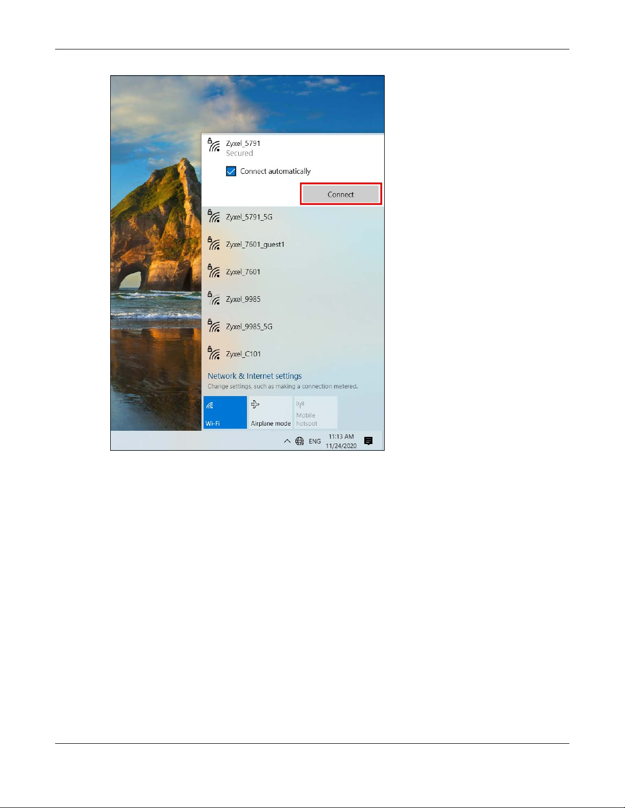
Chapter 4 Tutorials
The Zyxel Device sends the WiFi network settings to Windows using WPS. Windows displays “Getting
settings from the router”.
VMG/XMG/EMG/AM Series User’s Guide
56

Chapter 4 Tutorials
The WiFi device is then able to connect to the WiFi network securely.
4.3.2.2 WPS PIN Configuration
The WPS PIN (Personal Identification Number) method is a more secure version of WPS, used by WiFienabled devices such as printers. To use this connection method, you need to log into the Zyxel
Device’s Web Configurator.
1 Enable WiFi on the device you want to connect to the WiFi network. Then, note down the WPS PIN in the
device’s WiFi settings.
2 Log into Zyxel Device’s Web Configurator, and then go to the Network Setting > Wireless > WPS screen.
Enable WPS, and then click Apply.
3 Enable Method 2 PIN, and then click Apply. Enter the PIN of the WiFi device, and then click Register.
VMG/XMG/EMG/AM Series User’s Guide
57

Chapter 4 Tutorials
4 Within two minutes, enable WPS on the WiFi device.
The Zyxel Device authenticates the WiFi device using the PIN, and then sends the WiFi network settings to
the device using WPS. This process may take up to two minutes. The WiFi device is then able to connect
to the WiFi network securely.
4.4 USB Applications
This section shows you how to set up a cellular backup network, access shared folders and play files
through Window Media using a USB device.
4.4.1 File Sharing
This section shows you how to create a shared folder on your Zyxel Device through a USB device and
allow others to access the shared folder with File Sharing services.
VMG/XMG/EMG/AM Series User’s Guide
58

Chapter 4 Tutorials
4.4.1.1 Setting up File Sharing on Your Zyxel Device
1 Before enabling file sharing in the Zyxel Device, please set up your shared folders beforehand in your USB
device.
2 Connect your USB device to the USB port of the Zyxel Device.
3 Go to the Network Setting > USB Service > File Sharing screen. Enable File Sharing Services and click
Apply to activate the file sharing function. The Zyxel Device automatically adds your USB device to the
Information table.
4 Click Add New Share to add a new share.
VMG/XMG/EMG/AM Series User’s Guide
59

Chapter 4 Tutorials
5 The Add New Share screen appears.
5a Select your USB device from the Volume drop-down list box.
5b Enter a Description name for the added share to identify the device.
5c Click Browse and the Browse Directory screen appears.
5d On the Browse Directory screen, select the folder that you want to add as a share. In this example,
select BobShare and then click OK.
VMG/XMG/EMG/AM Series User’s Guide
60

Chapter 4 Tutorials
5e In Access Level, select Public to let the share to be accessed by all users connected to the Zyxel
Device. Otherwise, select Security to let the share to be accessed by specific users to access only.
Click OK to save the settings.
6 To set Access level to Security, you need to create one or more users accounts. Under Account
Management, click Add New User to open the User Account screen.
For information about the User
Account screen, see Section 26.2 on page 259.
7 After you create a new user account, the screen looks like the following.
VMG/XMG/EMG/AM Series User’s Guide
61

Chapter 4 Tutorials
8 File sharing is now configured. You can see the USB storage device listed in the table below.
4.4.1.2 Accessing Your Shared Files From a Computer
You can use Windows Explorer to access the USB storage devices connected to the Zyxel Device.
Note: This example shows you how to use Microsoft Windows 10 to browse shared files in a
share called (usb1_sda)Zoeys file. Refer to your operating system’s documentation for
how to browse your file structure.
1 Open Windows Explorer.
2 In the Windows Explorer’s address bar, enter a double backslash “\\” followed by the IP address of the
Zyxel Device (the default IP address of the Zyxel Device is 192.168.1.1), and then press [ENTER]. The
shared folder is visible.
3 Double-click on (usb1_sda)Zoeys file, and then enter the share's username and password if prompted.
4 After you access (usb1_sda)Zoeys file through your Zyxel Device, you do not have to log in again unless
you restart your computer.
VMG/XMG/EMG/AM Series User’s Guide
62
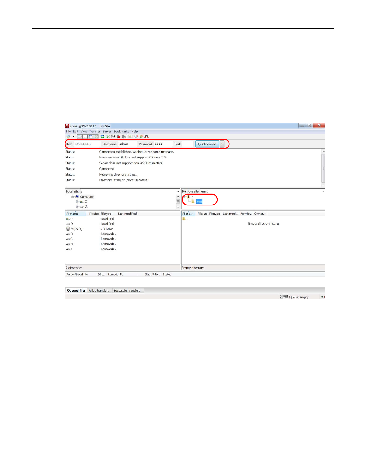
4.4.2 Using FTP
This section shows how to use an FTP program to access files on an USB storage device connected to
the Zyxel Device.
Note: This example uses the FileZilla FTP program to browse your shared files.
1 In FileZilla, enter the IP address of the Zyxel Device (The default IP is 192.168.1.1), your account’s
Username, Password and Port number, and then click Quickconnect. A screen asking for password
authentication appears.
File Sharing via Windows Explorer
Chapter 4 Tutorials
2 After you log in, the mnt folder is displayed as shown.
4.5 Network Security
This section shows you how to configure a Firewall rule, Parental Control rule, or MAC Filter rule.
4.5.1 Configuring a Firewall Rule
You can enable the firewall to protect your LAN computers from malicious attacks from the Internet.
1 Go to the Security > Firewall > General screen.
2 Select IPv4 Firewall/IPv6 Firewall to enable the firewall, and then click Apply.
VMG/XMG/EMG/AM Series User’s Guide
63

Chapter 4 Tutorials
3 Open the Access Control screen to create a rule.
VMG/XMG/EMG/AM Series User’s Guide
64

Chapter 4 Tutorials
4 Click Add New ACL Rule to set up a rule.
4a Filter Name: Enter a name to identify the firewall rule.
4b Source IP Address: Enter the IP address of the computer that initializes traffic for the application or
service.
4c Destination IP Address: Enter the IP address of the computer to which traffic for the application or
service is entering.
4d Protocol: Select the protocol (ALL, TCP/UDP, TCP, UDP, ICMP or ICMPv6) used to transport the
packets.
4e Policy: Select whether to (ACCEPT, DROP, or REJECT) the packets.
4f Direction: Select the direction (WAN to LAN, LAN to WAN, WAN to ROUTER, or LAN to ROUTER) of the
traffic to which this rule applies.
5 Select Enable Rate Limit to activate the rules you created. Click OK.
4.5.2 Parental Control
This section shows you how to configure rules for accessing the Internet using parental control.
VMG/XMG/EMG/AM Series User’s Guide
65

Chapter 4 Tutorials
The style and features of your parental control vary depending on the Zyxel Device you are using, see
Section 4.5.2.1 on page 66 and Section 4.5.2.2 on page 68 for more information.
4.5.2.1 Configuring Parental Control Schedule and Filter
Parental Control Profile (PCP) allows you to set up a rule for:
• Internet usage scheduling.
• Websites and URL keyword blocking.
Use this feature to:
• Limit the days and times a user can access the Internet.
• Limit the websites a user can access on the Internet.
This example shows you how to block a user from accessing the Internet during time for studying. It also
shows you how to stop a user from accessing specific websites.
Use the parameter below to configure a schedule rule and a URL keyword blocking rule.
PROFILE NAME
Study Day:
INTERNET ACCESS
SCHEDULE
Monday to Friday
Time:
8:00 to 11:00
13:00 to 17:00
NETWORK SERVICE SITE/ URL KEYWORD
Network Service Setting:
Block
Service Name:
HTTP
Protocol:
TCP
Port:
80
Block or Allow the Web Site:
Block the web URLs
Website:
gambling
Parental Control Screen
1 Select Enable under General to enable parental control. Then click Add New PCP to add a rule.
VMG/XMG/EMG/AM Series User’s Guide
66

Add New PCP Screen
Chapter 4 Tutorials
1 Under General:
1a Select Enable to enable the rule you are configuring.
1b Enter the Parental Control Profile Name given in the above parameter.
1c Select an user this rule applies to in Home Network User, then click Add. You will see the MAC
address of the user you just select in Rule List.
2 Under Internet Access Schedule:
2a Click Add New Time to add a second schedule.
VMG/XMG/EMG/AM Series User’s Guide
67

Chapter 4 Tutorials
2b Use the parameter give above to configure the time settings of your schedule.
3 Under Network Service:
3a In Network Service Setting, select Block.
3b Click Add New Service, then use the parameter given above to configure settings for the Internet
service you are blocking.
4 Under Site/ URL Keyword:
4a Select Block the web URLs in Block or Allow the Web Site.
4b Click Add, then use the parameter given above to configure settings for the URL keyword you are
blocking.
4c Select Redirect blocked site to Zyxel Family Safety page to redirect the web browser to the Zyxel
Family Safety page if he or she tries to access a website with the blocked URL keyword.
5 Click OK to save your settings.
4.5.2.2 Configuring a Parental Control Schedule
Parental Control Profile allows you to set up a schedule rule for Internet usage. Use this feature to limit
the days and times a user can access the Internet.
VMG/XMG/EMG/AM Series User’s Guide
68

Chapter 4 Tutorials
This example shows you how to block an user from accessing the Internet during time for studying. Use
the parameter below to configure a schedule rule.
PROFILE NAME START BLOCKING END BLOCKING REPEAT ON
Study 8:00 am 11:00 am from Monday to Friday
1:00 pm 5:00 pm from Monday to Friday
1 Click Add more Profile to open the Parental Control screen.
2 Use this screen to add a Parental Control rule.
2a Enter the Profile Name given in the above parameter.
2b Click on the switch to enable Internet Blocking.
2c Select a device, and then click Next to proceed.
3 Use this screen to edit the Parental Control schedule.
3a Click Add New Schedule to add a second schedule.
3b Use the parameter given above to configure the time settings of your schedules.
3c Click Save to save the settings.
VMG/XMG/EMG/AM Series User’s Guide
69

Chapter 4 Tutorials
4.5.3 Configuring a MAC Address Filter
You can use a MAC address filter to exclusively allow or permanently block someone from the WiFi
network.
This example shows that computer B is not allowed access to the WiFi network.
1 Go to the Security > MAC Filter > MAC Filter screen. Under MAC Address Filter, select Enable.
2 Click Add New Rule to add a new entry. Select Active, and then enter the Host Name and MAC Address
of computer B. Click Apply.
VMG/XMG/EMG/AM Series User’s Guide
70
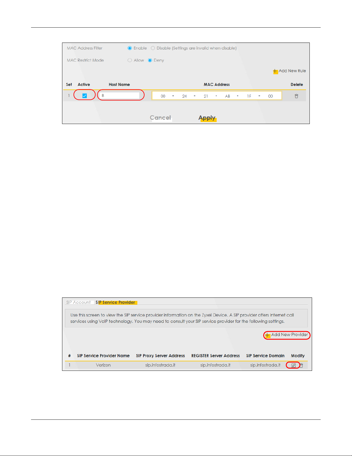
4.6 Internet Calls
This section shows you how to make Internet calls.
4.6.1 Configuring VoIP
Chapter 4 Tutorials
To make voice calls over the Internet, you must set up a Session Initiation Protocol (SIP) provider and SIP
account on the Zyxel Device. You should have an account with a SIP service provider already set up.
4.6.2 Adding a SIP Service Provider
Follow the steps below to add a SIP service provider.
1 Make sure your Zyxel Device is connected to the Internet.
2 Open the Web Configurator.
3 Go to the VoIP > SIP > SIP Service Provider screen. Click the Add New Provider button to add the SIP
Service Provider.
Figure 46 VoIP > SIP > SIP Service Provider
4 On the Add New Provider screen, select Enable SIP Service Provider.
5 Enter SIP Service Provider Name of up to 64 ASCII printable characters.
VMG/XMG/EMG/AM Series User’s Guide
71

Chapter 4 Tutorials
6 Enter SIP Proxy Server Address, SIP REGISTRAR Server Address, and SIP Service Domain provided by your
SIP service provider. Click OK to save your settings.
Figure 47 VoIP > SIP > SIP Service Provider > Add New Provider
4.6.3 Adding a SIP Account
The SIP account must be associated with the SIP service provider configured above. You may configure
several SIP accounts for the same service provider. Follow the steps below to set up your SIP account:
1 Make sure your Zyxel Device is connected to the Internet.
2 Open the Web Configurator.
3 Go to the VoIP > SIP > SIP Account screen.
4 Click the Add New Account button on the SIP Account screen to add a SIP account and map it to a
phone port.
VMG/XMG/EMG/AM Series User’s Guide
72

Chapter 4 Tutorials
Figure 48 VoIP > SIP > SIP Account
5 Under General, select Enable SIP Account, and then enter the SIP Account Number.
6 Under Authentication, enter Username and Password. Leave the other settings as default. Click OK to
save your settings.
Figure 49 VoIP > SIP > SIP Account > Add New Account/Edit
4.6.4 Configuring a Phone
You must now configure the phone port to use the SIP account you just configured.
1 Go to the VoIP > Phone > Phone Device screen.
VMG/XMG/EMG/AM Series User’s Guide
73

Chapter 4 Tutorials
2 Click the Modify icon of PHONE1 to configure PHONE1 on your Zyxel Device. The following screen
appears.
Figure 50 VoIP > Phone > Phone Device
3 Under SIP1 SIP Account to Make Outgoing Call, select SIP1 to have the phone connected to the first
phone port use the registered SIP1 account to make outgoing calls.
4 Under SIP Account(s) to Receive Incoming Call, select SIP1 to have the phone connected to the first
phone port receive phone calls for the SIP1 account. Click OK to save your changes.
Figure 51 VoIP > Phone > Phone Device > Edit
4.6.5 Making a VoIP Call
Follow these steps to make a phone calling using Voice over IP (VoIP).
1 Make sure you connect a telephone to phone port 1 on the Zyxel Device.
2 Make sure the Zyxel Device is turned on and connected to the Internet.
3 Pick up the phone receiver.
VMG/XMG/EMG/AM Series User’s Guide
74

Chapter 4 Tutorials
4 Dial the VoIP phone number you want to call.
4.6.6 Making a VoLTE Phone Call
Follow these steps to make a phone calling using Voice over LTE (VoLTE).
1 Make sure that your SIM card supports VoLTE or Vo3G.
2 Log into the Web Configurator.
3 Go to the Configuration > Voice > Voice Mode screen.
4 On the Voice Mode screen, select VoLTE service, and then click Apply.
The Zyxel Device restarts.
5 Connect an analog telephone to a PHONE port on the Zyxel Device.
6 Pick up the phone receiver.
7 Dial the phone number you want to call.
4.7 Device Maintenance
This section shows you how to upgrade device firmware, back up the device configuration and restore
the device to its previous or default settings.
4.7.1 Upgrading the Firmware
Upload the router firmware to the Zyxel Device for feature enhancements.
1 Download the correct firmware file from the download library at the Zyxel website. The model code for
the Zyxel Device in this example is ABLZ. Note the model code for your device. Unzip the file.
2 Go to the Maintenance > Firmware Upgrade screen.
3 Click Browse/Choose File and select the file with a ".bin" extension to upload. Click Upload.
VMG/XMG/EMG/AM Series User’s Guide
75

Chapter 4 Tutorials
4 This process may take up to two minutes to finish. After two minutes, log in again and check your new
firmware version in the Status screen.
4.7.2 Backing up the Device Configuration
Back up a configuration file allows you to return to your previous settings.
1 Go to the Maintenance > Backup/Restore screen.
2 Under Backup Configuration, click Backup. A configuration file is saved to your computer. In this case,
the Backup_Restore file is saved.
VMG/XMG/EMG/AM Series User’s Guide
76

Chapter 4 Tutorials
4.7.3 Restoring the Device Configuration
This section shows you how to restore a previously-saved configuration file from your computer to your
Zyxel Device.
1 Go to the Maintenance > Backup/Restore screen.
2 Under Restore Configuration, click Browse/Choose File, and then select the configuration file that you
want to upload. Click Upload.
VMG/XMG/EMG/AM Series User’s Guide
77

Chapter 4 Tutorials
3 The Zyxel Device automatically restarts after the configuration file is successfully uploaded. Wait for one
minute before logging into the Zyxel Device again. Go to the Connection Status page to check the
firmware version after the reboot.
VMG/XMG/EMG/AM Series User’s Guide
78

PART II
Technical Reference
79

Connection Status
5.1 Connection Status Overview
After you log into the Web Configurator, the Connection Status screen appears. You can configure
basic Internet access and wireless settings in this screen. It also shows the network status of the Zyxel
Device and computers/devices connected to it.
5.1.1 Connectivity
Use this screen to view the network connection status of the Zyxel Device and its clients.
Figure 52 Connectivity
CHAPTER 5
Click the Arrow icon ( ) to view IP addresses and MAC addresses of the wireless and wired devices
connected to the Zyxel Device.
Figure 53 Connectivity: Connected Devices
You can change the icon and name of a connected device. Place your mouse within the device
block, and an Edit icon ( ) will appear. Click the Edit icon, and you’ll see there are several icon
choices for you to select. Enter a name in the Device Name field for a connected device. Click to
enable
() i Internet Blocking for a connected device. Click Save to save your changes.
LTE Series User’s Guide
80

Figure 54 Connectivity: Edit
5.1.2 System Info
Chapter 5 Connection Status
Use this screen to view the basic system information of the Zyxel Device.
Figure 55 System Info
Click the Arrow icon ( ) to view more information on the status of your firewall and interfaces (WAN,
LAN, and WLAN).
LTE Series User’s Guide
81

Chapter 5 Connection Status
Figure 56 System Info: Detailed Information
Figure 57
Each field is described in the following table.
Table 13 System Info: Detailed Information
LABEL DESCRIPTION
Host Name This field displays the Zyxel Device system name. It is used for identification.
Model Name This shows the model number of your Zyxel Device.
Serial Number This field displays the serial number of the Zyxel Device.
Firmware Version This is the current version of the firmware inside the Zyxel Device.
System Up Time This field displays how long the Zyxel Device has been running since it last started up. The
Interface Status
Virtual ports are shown here. You can see the ports in use and their transmission rate.
WAN Information (These fields display when you have a WAN connection.)
Link Type This field displays the type of WAN connection that the Zyxel Device is currently using, such
APN This field displays the Access Point Name (APN).
Mode This field displays the current mode of your Zyxel Device.
IP Address This field displays the current IP address of the Zyxel Device in the WAN.
IP Subnet Mask This field displays the current subnet mask in the WAN.
IPv6 Address This field displays the current IPv6 address of the Zyxel Device in the WAN.
Zyxel Device starts up when you plug it in, when you restart it (Maintenance > Reboot), or
when you reset it.
as Cellular WAN or Ethernet.
LTE Series User’s Guide
82

Chapter 5 Connection Status
Table 13 System Info: Detailed Information (continued)
LABEL DESCRIPTION
Primary DNS
server
Secondary DNS
server
Primary DNSv6
server
Secondary
DNSv6 server
LAN Information
IP Address This is the current IP address of the Zyxel Device in the LAN.
IPv6 Address This is the current IPv6 address of the Zyxel Device in the LAN.
IPv6 Link Local
Address
Subnet Mask This is the current subnet mask in the LAN.
DHCP This field displays what DHCP services the Zyxel Device is providing to the LAN. The possible
Security
Firewall This displays the firewall’s current security level (High, Medium, Low, or Disabled).
WLAN Information
MAC Address This shows the WiFi adapter MAC (Media Access Control) Address of the WiFi interface.
Status This displays whether the WLAN is activated.
SSID This is the descriptive name used to identify the Zyxel Device in a WLAN.
Channel This is the channel number currently used by the WiFi interface.
Security This displays the type of security mode the WiFi interface is using in the WLAN.
802.11 Mode This displays the type of 802.11 mode the WiFi interface is using in the WLAN.
WPS This displays whether WPS is activated on the WiFi interface.
This field displays the first DNS server address assigned by the ISP.
This field displays the second DNS server address assigned by the ISP.
This field displays the first DNS server IPv6 address assigned by the ISP.
This field displays the second DNS server IPv6 address assigned by the ISP.
This field displays the current link-local address of the Zyxel Device for the LAN interface.
A link-local address is a special type of the IP address that is therefore only valid for
communication within the local network segment or broadcast domain of the device.
Typically, link-local addresses are used for automatic address configuration and neighbor
discovery protocols.
values are:
Server - The Zyxel Device is a DHCP server in the LAN. It assigns IP addresses to other
computers in the LAN.
Relay - The Zyxel Device acts as a surrogate DHCP server and relays DHCP requests and
responses between the remote server and the clients.
None - The Zyxel Device is not providing any DHCP services to the LAN.
5.1.3 Cellular Info
Use this screen to view cellular connection information, details on cellular signal strength that you can
use as a reference for positioning the Zyxel Device, as well as SIM card and module information.
LTE Series User’s Guide
83

Chapter 5 Connection Status
Figure 58 Cellular Info
Click the Arrow icon ( ) to view the more information on the cellular connection.
Figure 59 Cellular Info: Detailed Information
The following table describes the labels in this screen.
Table 14 Cellular Info: Detailed Information
LABEL DESCRIPTION
Module Information
IMEI This shows the International Mobile Equipment Identity of the Zyxel Device.
Module SW
Version
SIM Status
This shows the software version of the cellular network module.
LTE Series User’s Guide
84

Chapter 5 Connection Status
Table 14 Cellular Info: Detailed Information
LABEL DESCRIPTION
SIM Card Status This displays the SIM card status:
None - the Zyxel Device does not detect that there is a SIM card inserted.
Available - the SIM card could either have or doesn’t have PIN code security.
Locked - the SIM card has PIN code security, but you did not enter the PIN code yet.
Blocked - you entered an incorrect PIN code too many times, so the SIM card has been locked;
call the ISP for a PUK (Pin Unlock Key) to unlock the SIM card.
Error - the Zyxel Device detected that the SIM card has errors.
IMSI This displays the International Mobile Subscriber Identity (IMSI) of the installed SIM card. An IMSI is
ICCID
PIN Protection A PIN (Personal Identification Number) code is a key to a SIM card. Without the PIN code, you
PIN Remaining
Attempts
IP Passthrough Status
IP Passthrough
Enable
IP Passthrough
Mode
a unique ID used to identify a mobile subscriber in a mobile network.
Integrated Circuit Card Identifier (ICCID). This is the serial number of the SIM card.
cannot use the SIM card.
Shows Enable if the service provider requires you to enter a PIN to use the SIM card.
Shows Disable if the service provider lets you use the SIM without inputting a PIN.
This is how many more times you can try to enter the PIN code before the ISP blocks your SIM
card.
This displays if IP Passthrough is enabled on the Zyxel Device.
IP Passthrough allows a LAN computer on the local network of the Zyxel Device to have access
to web services using the public IP address. When IP Passthrough is configured, all traffic is
forwarded to the LAN computer and will not go through NAT.
This displays the IP Passthrough mode.
This displays Dynamic and the Zyxel Device will allow traffic to be forwarded to the first LAN
computer requesting an IP address from the Zyxel Device.
This displays Fixed and the Zyxel Device will allow traffic to be forwarded to a specific LAN
computer on the local network of the Zyxel Device.
Cellular Status
Cellular Status This displays the status of the cellular Internet connection.
Data Roaming This displays if data roaming is enabled on the Zyxel Device.
4G roaming is to use your Zyxel Device in an area which is not covered by your service provider.
Enable roaming to ensure that your Zyxel Device is kept connected to the Internet when you are
traveling outside the geographical coverage area of the network to which you are registered.
Operator This displays the name of the service provider.
PLMN This displays the PLMN number.
Service
Information
Note: If the cellular service provider supports carrier aggregation (CA), then this
section displays statistics for the connection’s primary component carrier
(PCC).
Access
Technology
Band This displays the current cellular band of your Zyxel Device (WCDMA2100).
RSSI This displays the strength of the cellular signal between an associated cellular station and the
This displays the type of the mobile network (such as LTE, UMTS, GSM) to which the Zyxel Device is
connecting.
Zyxel Device.
LTE Series User’s Guide
85

Chapter 5 Connection Status
Table 14 Cellular Info: Detailed Information
LABEL DESCRIPTION
Cell ID This shows the cell ID, which is a unique number used to identify the Base Transceiver Station to
which the Zyxel Device is connecting.
The value depends on the Current Access Technology:
• For GPRS, it is the Cell Identity as specified in 3GPP-TS.25.331.
• For UMTS, it is the Cell Identity as defined in SIB3 3GPP-TS.25.331, 3GPP-TS.24.008.
• For LTE, it is the 28-bit binary number Cell Identity as specified in SIB1 in 3GPP-TS.36.331.
The value is ‘0’ (zero) or ‘N/A’ if there is no network connection.
Physical Cell ID This shows the Physical Cell ID (PCI), which are queries and replies between the Zyxel Device and
the mobile network it is connecting to. The normal range is 1 to 504.
UL Bandwidth
(MHz)
DL Bandwidth
(MHz)
RFCN This displays the Radio Frequency Channel Number of DL carrier frequency used by the mobile
RSRP This displays the Reference Signal Receive Power (RSRP), which is the average received power
This shows the cellular channel bandwidth from the device to the base station. According to
3GPP specifications, the bandwidths defined by the standard are 1.4, 3, 5, 10, 15, and 20 MHz.
The wider the bandwidth the higher the throughput.
This shows the cellular channel bandwidth from the base station to the device. According to
3GPP specifications, the bandwidths defined by the standard are 1.4, 3, 5, 10, 15, and 20 MHz.
The wider the bandwidth the higher the throughput.
network to which the Zyxel Device is connecting.
The value depends on the Current Access Technology:
• For GPRS, it is the ARFCN (Absolute Radio-Frequency Channel Number) as specified in 3GPPTS.45.005.
• For UMTS, it is the UARFCN (UTRA Absolute Radio-Frequency Channel Number) as specified in
3GPP-TS.25.101.
• For LTE, it is the EARFCN (E-UTRA Absolute Radio-Frequency Channel Number) as specified in
3GPP-TS.36.101.
The value is ‘0’ (zero) or ‘N/A’ if there is no network connection.
of all Resource Element (RE) that carry cell-specific Reference Signals (RS) within the specified
bandwidth.
The received RSRP level of the connected E-UTRA cell, in dBm, is as specified in 3GPP-TS.36.214.
The reporting range is specified in 3GPP-TS.36.133.
An undetectable signal is indicated by the lower limit, example -140 dBm.
This parameter is for LTE only. The normal range is -30 to -140. The value is -140 if the Current
Access Technology is not LTE. The value is ‘N/A’ if there is no network connection.
RSRQ This displays the Reference Signal Receive Quality (RSRQ), which is the ratio of RSRP to the E-UTRA
RSCP This displays the Received Signal Code Power, which measures the power of channel used by
carrier RSSI and indicates the quality of the received reference signal.
The received RSRQ level of the connected E-UTRA cell, in 0.1 dB, is as specified in 3GPP-TS.36.214.
An undetectable signal is indicated by the lower limit, example -240.
This parameter is for LTE only. The normal range is -30 to -240. The value is -240 if the Current
Access Technology is not LTE. The value is ‘N/A’ if there is no network connection.
the Zyxel Device.
The received signal level, in dBm, is of the CPICH channel (Ref. 3GPP TS 25.133). An
undetectable signal is indicated by the lower limit, example -120 dBm.
This parameter is for UMTS only. The normal range is -30 to -120. The value is -120 if the Current
Access Technology is not UMTS. The value is ‘N/A’ if there is no network connection.
LTE Series User’s Guide
86

Chapter 5 Connection Status
Table 14 Cellular Info: Detailed Information
LABEL DESCRIPTION
EcNo This displays the ratio (in dB) of the received energy per chip and the interference level.
The measured EcNo is in 0.1 dB and is received in the downlink pilot channel. An undetectable
signal is indicated by the lower limit, example -240 dB.
This parameter is for UMTS only. The normal range is -30 to -240. The value is -240 if the Current
Access Technology is not UMTS or there is no network connection.
TAC This displays the Tracking Area Code (TAC), which is used to identify the country of a mobile
subscriber.
The physical cell ID of the connected E-UTRAN cell, is as specified in 3GPP-TS.36.101.
This parameter is for LTE only. The value is ‘0’ (zero) or ‘N/A’ if the Current Access Technology is
not LTE or there is no network connection.
LAC This displays the 2-octet Location Area Code (LAC), which is used to identify a location area
within a PLMN.
The LAC of the connected cell is as defined in SIB 1 [3GPP-TS.25.331]. The concatenation of
PLMN ID (MCC+MNC) and LAC uniquely identifies the LAI (Location Area ID) [3GPP-TS.23.003].
This parameter is for UMTS or GPRS. The value is ‘0’ (zero) if the Current Access Technology is not
UMTS or GPRS. The value is ‘N/A’ if there is no network connection.
RAC
This displays the RAC (Routing Area Code), which is used in mobile network “packet domain
service” (PS) to identify a routing area within a location area.
In a mobile network, it uses LAC (Location Area Code) to identify the geographical location for
the old 3G voice only service, and use RAC to identify the location of data service like HSDPA or
LTE.
The RAC of the connected UTRAN cell is as defined in SIB 1 [3GPP-TS.25.331]. The concatenation
of PLMN ID (MCC+MNC), LAC, and RAC uniquely identifies the RAI (Routing Area ID) [3GPPTS.23.003].
This parameter is for UMTS or GPRS. The value is ‘0’ (zero) if the Current Access Technology is not
UMTS or GPRS. The value is ‘N/A’ if there is no network connection.
BSIC The Base Station Identity Code (BSIC), which is a code used in GSM to uniquely identify a base
station.
This parameter is for GPRS only. The value is ‘0’ (zero) if the Current Access Technology is not
GPRS. The value is ‘N/A’ if there is no network connection.
SINR This displays the Signal to Interference plus Noise Ratio (SINR) in dB. This is also a measure of signal
quality and used by the UE (User Equipment) to calculate the Channel Quality Indicator (CQI)
that it reports to the network. A negative value means more noise than signal.
CQI This displays the Channel Quality Indicator (CQI). It is an indicator carrying the information on
MCS MCS stands for modulation coding scheme. The base station selects MCS based on current
RI This displays the Rank Indication, one of the control information that a UE will report to eNodeB
PMI This displays the Precoding Matrix Indicator (PMI).
how good/bad the communication channel quality is.
radio conditions. The higher the MCS the more bits can be transmitted per time unit.
(Evolved Node-B) on either PUCCH (Physical Uplink Control Channel) or PUSCH (Physical Uplink
Shared Channel) based on uplink scheduling.
PMI is for transmission modes 4 (closed loop spatial multiplexing), 5 (multi-user MIMO), and 6
(closed loop spatial multiplexing using a single layer).
PMI determines how cellular data are encoded for the antennas to improve downlink rate.
LTE Series User’s Guide
87

5.1.4 WiFi Settings
Use this screen to enable or disable the main wireless network. When the switch turns blue ( ), the
function is enabled. You can use this screen or the QR code on the upper right corner to check the SSIDs
(WiFi network name) and passwords of the main wireless networks. If you want to show or hide your WiFi
passwords, click the Eye icon ( ).
Figure 60 WiFi Settings
Click the Arrow icon ( ) to configure the SSIDs and/or passwords for your main wireless networks. Click
the Eye icon ( ) to display the characters as you enter the WiFi Password.
Chapter 5 Connection Status
Figure 61 WiFi Settings: Configuration
Each field is described in the following table.
Table 15 WiFi Settings: Configuration
LABEL DESCRIPTION
2.4G / 5G WiFi Click this switch to enable or disable the 2.4 GHz / 5 GHz WiFi network. When the switch turns
WiFi Name The SSID (Service Set IDentity) identifies the service set with which a wireless device is
WiFi Password If you selected Random Password, this field displays a pre-shared key generated by the Zyxel
blue , the function is enabled.
associated. Wireless devices associating to the access point (AP) must have the same SSID.
Enter a descriptive name (up to 32 English keyboard characters) for the wireless LAN.
Device.
If you did not select Random Password, you can manually type a pre-shared key from 8 to 64
case-sensitive keyboard characters.
Click the Eye icon to show or hide the password for your wireless network. When the Eye icon
is slashed , you’ll see the password in plain text. Otherwise, it’s hidden.
LTE Series User’s Guide
88

Table 15 WiFi Settings: Configuration (continued)
LABEL DESCRIPTION
Random Password Select this option to have the Zyxel Device automatically generate a password. The WiFi
Password field will not be configurable when you select this option.
Hide WiFi network
name
Save Click Save to save your changes.
Select this check box to hide the SSID in the outgoing beacon frame so a station cannot
obtain the SSID through scanning using a site survey tool.
Note: Disable WPS in the Network Setting > Wireless > WPS screen to hide the SSID.
5.1.5 Guest WiFi Settings
Use this screen to enable or disable the guest wireless network. When the switch turns blue ( ), the
function is enabled. You can use this screen or the QR code on the upper right corner to check the SSIDs
(WiFi network name) and passwords of the guest wireless networks. If you want to show or hide your WiFi
passwords, click the Eye icon ( ).
Figure 62 Guest WiFi Settings
Chapter 5 Connection Status
Click the Arrow icon ( ) to configure the SSIDs and/or passwords for the guest wireless networks. Click
the Eye icon ( ) to display the characters as you enter the WiFi Password.
Figure 63 Guest WiFi Settings: Configuration
LTE Series User’s Guide
89

Chapter 5 Connection Status
Each field is described in the following table.
Table 16 Guest WiFi Settings: Configuration
LABEL DESCRIPTION
2.4G / 5G WiFi Click this switch to enable or disable the 2.4 GHz / 5 GHz wireless network. When the switch
WiFi Name The SSID (Service Set IDentity) identifies the service set with which a wireless device is
WiFi Password If you selected Random Password, this field displays a pre-shared key generated by the Zyxel
Random Password Select this option to have the Zyxel Device automatically generate a password. The WiFi
Hide WiFi network
name
turns blue , the function is enabled.
associated. Wireless devices associating to the access point (AP) must have the same SSID.
Enter a descriptive name (up to 32 English keyboard characters) for the wireless LAN.
Device.
If you did not select Random Password, you can manually type a pre-shared key from 8 to 64
case-sensitive keyboard characters.
Click the Eye icon to show or hide the password for your wireless network. When the Eye icon
is slashed , you’ll see the password in plain text. Otherwise, it’s hidden.
Password field will not be configurable when you select this option.
Select this check box to hide the SSID in the outgoing beacon frame so a station cannot
obtain the SSID through scanning using a site survey tool.
Note: Disable WPS in the Network Setting > Wireless > WPS screen to hide the SSID.
Save Click Save to save your changes.
5.1.6 LAN
Use this screen to view the LAN IP address, subnet mask, and DHCP settings of your Zyxel Device.
Figure 64 LAN
Click the Arrow icon ( ) to configure the LAN IP settings and DHCP setting for your Zyxel Device.
LTE Series User’s Guide
90

Chapter 5 Connection Status
Figure 65 LAN Setup
Each field is described in the following table.
Table 17 Status Screen
LABEL DESCRIPTION
LAN IP Setup
IP Address Enter the LAN IPv4 IP address you want to assign to your Zyxel Device in dotted decimal
Subnet Mask Type the subnet mask of your network in dotted decimal notation, for example 255.255.255.0
IP Addressing Values
Beginning IP
Address
Ending IP
Address
DHCP Server State
DHCP Server
Lease Time
Days/Hours/
Minutes
Save Click Save to save your changes.
notation, for example, 192.168.1.1 (factory default).
(factory default). Your Zyxel Device automatically computes the subnet mask based on the
IP Address you enter, so do not change this field unless you are instructed to do so.
This field specifies the first of the contiguous addresses in the IP address pool.
This field specifies the last of the contiguous addresses in the IP address pool.
This is the period of time a DHCP-assigned address is valid, before it expires.
When a client connects to the Zyxel Device, DHCP automatically assigns the client an IP
addresses from the IP address pool. DHCP leases each addresses for a limited period of time,
which means that past addresses are “recycled” and made available for future
reassignment to other devices.
Enter the lease time of the DHCP server.
LTE Series User’s Guide
91

6.1 Overview
This chapter discusses the Zyxel Device’s Broadband screens. Use these screens to configure your Zyxel
Device for Internet access.
A WAN (Wide Area Network) connection is an outside connection to another network or the Internet. It
connects your private networks, such as a LAN (Local Area Network) and other networks, so that a
computer in one location can communicate with computers in other locations.
Figure 66 LAN and WAN
CHAPTER 6
Broadband
6.1.1 What You Can Do in this Chapter
• Use the Broadband screen to view a WAN interface. You can also configure the WAN settings on the
Zyxel Device for Internet access (Section 6.2 on page 93).
• Use the WAN Backup screen to configure your Zyxel Device’s WAN backup settings (Section 6.3 on
page 98).
• Use the Ethernet WAN screen to convert LAN port number four as a WAN port or restore the Ethernet
WAN port to a LAN port (Section 6.4 on page 99).
• Use the Cellular WAN screen to configure a cellular WAN connection (Section 6.5 on page 100).
• Use the Cellular APN screen to configure the APN setting (Section 6.6 on page 100).
• Use the Cellular SIM screen to enter the PIN of your SIM card (Section 6.7 on page 103).
• Use the Cellular Band screen to view or edit a cellular WAN interface. You can also configure the
WAN settings on the Zyxel Device for Internet access (Section 6.2 on page 93).
• Use the Cellular PLMN screen to display available Public Land Mobile Networks (Section 6.9 on page
105).
LTE Series User’s Guide
92

• Use the Cellular IP Passthrough screen to configure a cellular WAN connection (Section 6.10 on page
108)
• Use the Cellular Lock screen to configure the base station you choose to connect to (Section 6.11 on
page 109).
Table 18 WAN Setup Overview
LAYER-2 INTERFACE INTERNET CONNECTION
CONNECTION DSL LINK TYPE MODE ENCAPSULATION CONNECTION SETTINGS
Ethernet
N/A
6.1.2 What You Need to Know
The following terms and concepts may help as you read this chapter.
WAN IP Address
The WAN IP address is an IP address for the Zyxel Device, which makes it accessible from an outside
network. It is used by the Zyxel Device to communicate with other devices in other networks. The ISP
dynamically assigns it each time the Zyxel Device tries to access the Internet.
Chapter 6 Broadband
Routing IPoE WAN IPv4/IPv6 IP address, NAT, DNS
server and routing feature.
APN
An Access Point Name (APN) is the name of a gateway between a cellular network and another
network, such as the Internet. The Zyxel Device requires an APN to connect to a cellular network.
Different APNs may provide different services, such as Internet access or MMS (Multi-Media Messaging
Service), and different charging methods.
6.1.3 Before You Begin
You may need to know your Internet access settings such as APN, WAN IP address and SIM card’s PIN
code if the INTERNET light on your Zyxel Device is off. Get this information from your service provider.
6.2 Broadband
Use this screen to change your Zyxel Device’s Internet access settings. The summary table shows you the
configured WAN services (connections) on the Zyxel Device. Use information provided by your ISP to
configure WAN settings.
Click Network Setting > Broadband to access this screen.
LTE Series User’s Guide
93
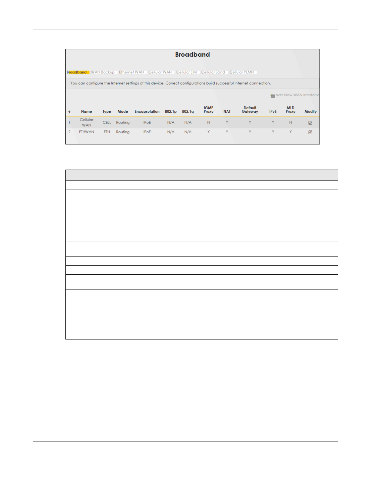
Chapter 6 Broadband
Figure 67 Network Setting > Broadband
The following table describes the labels in this screen.
Table 19 Network Setting > Broadband
LABEL DESCRIPTION
# This is the index number of the entry.
Name This is the service name of the connection.
Type This shows whether it is a cellular or Ethernet connection.
Mode This shows the connection is in routing mode.
Encapsulation This is the method of encapsulation used by this connection.
802.1p This indicates the 802.1p priority level assigned to traffic sent through this connection. This
802.1q This indicates the VLAN ID number assigned to traffic sent through this connection. This displays
IGMP Proxy This shows whether the Zyxel Device act as an IGMP proxy on this connection.
NAT This shows whether NAT is activated or not for this connection.
Default
Gateway
IPv6 This shows whether IPv6 is activated or not for this connection. IPv6 is not available when the
MLD Proxy This shows whether Multicast Listener Discovery (MLD) is activated or not for this connection. MLD
Modify Click the Edit or Modify icon to configure the WAN connection.
displays N/A when there is no priority level assigned.
N/A when there is no VLAN ID number assigned.
This shows whether the Zyxel Device use the WAN interface of this connection as the system
default gateway.
connection uses the bridging service.
is not available when the connection uses the bridging service.
Click the Delete icon to remove the WAN connection.
6.2.1 Add/Edit Internet Connection
Click the Edit or Modify icon next to a WAN interface to open the following screen. Use this screen to
configure a WAN connection.
LTE Series User’s Guide
94

Chapter 6 Broadband
Figure 68 Network Setting > Broadband > Add/Edit New WAN Interface
The following table describes the labels in this screen.
Table 20 Network Setting > Broadband > Add/Edit New WAN Interface
LABEL DESCRIPTION
General Click this switch to enable or disable the interface. When the switch goes to the right , the
Name This is the service name of the connection.
Type This shows the type of the connection the Zyxel Device is currently associated with.
Mode This shows the connection is in Routing or Bridge mode.
function is enabled. Otherwise, it is not.
If the Zyxel Device is in routing mode, your ISP gives you one IP address only and you want
multiple computers to share an Internet account.
LTE Series User’s Guide
95

Chapter 6 Broadband
Table 20 Network Setting > Broadband > Add/Edit New WAN Interface (continued)
LABEL DESCRIPTION
Encapsulation This is the method of encapsulation used by this connection.
IPv4/IPv6 Mode This shows IPv4 IPv6 DualStack.
IPv4 IPv6 DualStack allows the Zyxel Device to run IPv4 and IPv6 at the same time.
VLAN Click this switch to enable or disable VLAN on this WAN interface. When the switch goes to the
802.1p IEEE 802.1p defines up to 8 separate traffic types by inserting a tag into a MAC-layer frame that
802.1q Type the VLAN ID number (from 1 to 4094) for traffic through this connection.
MTU
MTU Enter the MTU (Maximum Transfer Unit) size for this traffic.
IP Address
Obtain an IP
Address
Automatically
Static IP Address Select this option If the ISP assigned a fixed IP address.
IP Address Enter the static IP address provided by your ISP.
Subnet Mask Enter the subnet mask provided by your ISP.
Gateway IP
Address
DNS Server
Primary DNS
Server
Secondary DNS
Server
Routing Feature
NAT Click this switch to activate or deactivate NAT on this connection. When the switch goes to the
IGMP Proxy Internet Group Multicast Protocol (IGMP) is a network-layer protocol used to establish
Apply as Default
Gateway
right , the function is enabled. Otherwise, it is not.
contains bits to define class of service.
Select the IEEE 802.1p priority level (from 0 to 7) to add to traffic through this connection. The
greater the number, the higher the priority level.
A static IP address is a fixed IP that your ISP gives you. A dynamic IP address is not fixed; the ISP
assigns you a different one each time you connect to the Internet. Select this if you have a
dynamic IP address.
Enter the gateway IP address provided by your ISP.
Select Obtain DNS Info Automatically if you want the Zyxel Device to use the DNS server
addresses assigned by your ISP.
Select Use Following Static DNS Address if you want the Zyxel Device to use the DNS server
addresses you configure manually.
Enter the first DNS server address assigned by the ISP.
Enter the second DNS server address assigned by the ISP.
right , the function is enabled.
membership in a Multicast group - it is not used to carry user data.
Click this switch to have the Zyxel Device act as an IGMP proxy on this connection. When the
switch goes to the right , the function is enabled.
This allows the Zyxel Device to get subscribing information and maintain a joined member list for
each multicast group. It can reduce multicast traffic significantly.
Click this switch to have the Zyxel Device use the WAN interface of this connection as the system
default gateway. When the switch goes to the right , the function is enabled.
LTE Series User’s Guide
96

Chapter 6 Broadband
Table 20 Network Setting > Broadband > Add/Edit New WAN Interface (continued)
LABEL DESCRIPTION
Fullcone NAT Click this switch to enable or disable fullcone NAT on this connection. When the switch goes to
the right , the function is enabled.
This field is available only when you activate NAT.
In fullcone NAT, the Zyxel Device maps all outgoing packets from an internal IP address and port
to a single IP address and port on the external network. The Zyxel Device also maps packets
coming to that external IP address and port to the internal IP address and port.
DHCPC Options
Request Options Select Option 43 to have the Zyxel Device automatically add vendor specific information in the
DHCP packets to request the vendor specific options from the DHCP server.
Select Option 120 to have the Zyxel Device get the IP address or a fully-qualified domain name
of SIP server from DHCP.
Select Option 121 to have the Zyxel Device push static routes to clients.
Sent Options
option 60 Select this and enter the device identity you want the Zyxel Device to add in the DHCP discovery
packets that go to the DHCP server.
Vendor ID Enter the Vendor Class Identifier, such as the type of the hardware or firmware.
option 61 Select this and enter any string that identifies the device.
IAID Enter the Identity Association Identifier (IAID) of the device, for example, the WAN connection
index number.
DUID Enter the hardware type, a time value and the MAC address of the device.
option 125 Select this to have the Zyxel Device automatically generate and add vendor specific
IPv6 Address
Obtain an IPv6
Address
Automatically
Static IPv6
Address
IPv6 Address Enter an IPv6 IP address that your ISP gave to you for this WAN interface.
Prefix Length Enter the address prefix length to specify how many most significant bits in an IPv6 address
IPv6 Default
Gateway
IPv6 DNS Server
Obtain IPv6 DNS
Info
Automatically
Use Following
Static IPv6 DNS
Address
Primary DNS
Server
Secondary DNS
Server
IPv6 Routing Feature
parameters in the DHCP discovery packets that go to the DHCP server.
Select Obtain an IPv6 Address Automatically if you want to have the Zyxel Device use the IPv6
prefix from the connected router’s Router Advertisement (RA) to generate an IPv6 address.
Select Static IPv6 Address if you have a fixed IPv6 address assigned by your ISP. When you select
this, the following fields appear.
compose the network address.
Enter the IP address of the next-hop gateway. The gateway is a router or switch on the same
segment as your Zyxel Device's interface(s). The gateway helps forward packets to their
destinations.
Select Obtain IPv6 DNS Info Automatically to have the Zyxel Device get the IPv6 DNS server
addresses from the ISP automatically.
Select Use Following Static IPv6 DNS Address to have the Zyxel Device use the IPv6 DNS server
addresses you configure manually.
Enter the first IPv6 DNS server address assigned by the ISP.
Enter the second IPv6 DNS server address assigned by the ISP.
LTE Series User’s Guide
97

Table 20 Network Setting > Broadband > Add/Edit New WAN Interface (continued)
LABEL DESCRIPTION
MLD Proxy
Enable
Apply as Default
Gateway
Cancel Click Cancel to exit this screen without saving.
Apply Click Apply to save your changes.
Select this check box/option to have the Zyxel Device act as an MLD proxy on this connection.
This allows the Zyxel Device to get subscription information and maintain a joined member list for
each multicast group. It can reduce multicast traffic significantly.
Select this option to have the Zyxel Device use the WAN interface of this connection as the
system default gateway.
6.3 WAN Backup
Use this screen to configure your Zyxel Device’s Internet settings if the wired connection is down. You
can use an alternative network, and assign an IP address to verify the accessibility of the Internet and
the time interval allowed between each connection check.
Click Network Setting > Broadband > WAN Backup to display the following screen.
Chapter 6 Broadband
Note: This feature is only available if Ethernet WAN > State is enabled.
Figure 69 Network Setting > Broadband > WAN Backup
The following table describes the fields in this screen.
Table 21 Network Setting > Broadband > WAN Backup
LABEL DESCRIPTION
WAN Backup Enable Select Enable to have the Zyxel Device use the cellular connection as your WAN or a
Primary WAN This field displays the connection the Zyxel Device would use first when the wired
backup when the wired WAN connection fails.
WAN connection fails. You can choose Ethernet or Cellular as the primary WAN
connection for your Zyxel Device.
LTE Series User’s Guide
98

Chapter 6 Broadband
Table 21 Network Setting > Broadband > WAN Backup (continued)
LABEL DESCRIPTION
The Destination for
Connection Check
Configure this field to test your Zyxel Device's WAN accessibility. Type the IP address
of a reliable nearby computer (for example, your ISP's DNS server address).
Note: If you activate either traffic redirect or dial backup, you must
configure at least one IP address here. When using a WAN backup
connection, the Zyxel Device periodically pings the addresses
configured here and uses the other WAN backup connection (if
configured) if there is no response.
Connection Check Interval When the Zyxel Device is using a lower priority connection (usually a WAN backup
connection), it periodically checks to whether or not it can use a higher priority
connection. Type the number of seconds (30 recommended) for the Zyxel Device to
wait between checks. Allow more time if your destination IP address handles lots of
traffic.
Check Fail Limit Type the number of times that your Zyxel Device will ping the IP addresses
Cancel Click Cancel to exit this screen without saving.
Apply Click Apply to save your changes.
configured in the Destination for Connection Check field without getting a response
before switching to a WAN backup connection (or a different WAN backup
connection).
6.4 Ethernet WAN
Use this screen to have a LAN port act as an Ethernet WAN port. When the switch goes to the right, the
LAN port acts as an Ethernet WAN port. Otherwise, the LAN port remains as a LAN port. Click Apply to
save your changes back to the Zyxel Device.
Click Network Setting > Broadband > Ethernet WAN to display the following screen.
Figure 70 Network Setting > Broadband > Ethernet WAN
LTE Series User’s Guide
99

6.5 Cellular WAN
Click Network Setting > Broadband > Cellular WAN to display the following screen. Use this screen to
enable data roaming and network monitoring when the Zyxel Device cannot ping a base station.
Note: Roaming charges may apply when Data Roaming is enabled.
Figure 71 Network Setting > Broadband > Cellular WAN
Chapter 6 Broadband
The following table describes the fields in this screen.
Table 22 Network Setting > Broadband > Cellular WAN
LABEL DESCRIPTION
Antenna
Antenna Select Select between External or Internal Antenna for your Zyxel Device.
Roaming
Data Roaming Click this to enable ( ) data roaming on the Zyxel Device.
With cellular roaming, a SIM card works in areas which are not covered by the SIM’s service
provider. Enable roaming to keep the Zyxel Device connected to the Internet when you are
traveling outside the geographical coverage area of the network to which you are registered,
such as a different country.
Note: Roaming charges may apply when Data Roaming is enabled.
Apply Click this to save your changes.
Cancel Click this to exit this screen without saving.
6.6 Cellular APN
Click Network Setting > Broadband > Cellular APN to display the following screen. Use this screen to
manage the APNs that Zyxel Device is connected to.
Note: This feature is only available on certain models. For details, see the features comparison
table at Section 1.1 on page 16.
LTE Series User’s Guide
100
 Loading...