

Page 1
Default Login Details
User’s Guide
LTE7460-M608
4G LTE-A Outdoor CPE
LAN IP Address https://192.168.1.1
User Name admin
Password 1234
Version 1.00 Edition 1, 10/2016
Copyright © 2016 Zyxel Communications Corporation
Page 2

IMPORTANT!
READ CAREFULLY BEFORE USE.
KEEP THIS GUIDE FOR FUTURE REFERENCE.
This is a User’s Guide for a series of products. Not all products support all firmware features. Screenshots
and graphics in this book may differ slightly from your product due to differences in your product
firmware or your computer operating system. Every effort has been made to ensure that the information
in this manual is accurate.
Related Documentation
•Quick Start Guide
The Quick Start Guide shows how to connect the LTE and access the Web Configurator.
• Web Configurator Online Help
Click the help icon in any screen for help in configuring that screen and supplementary information.
•More Information
Go to support.zyxel.com to find other information on the LTE7460-M608
.
LTE7460-M608 User’s Guide
2
Page 3

Contents Overview
Contents Overview
User’s Guide ........................................................................................................................................8
Introduction ............................................................................................................................................. 9
Introducing the Web Configurator ..................................................................................................... 11
Tutorials .................................................................................................................................................. 17
Technical Reference ........................................................................................................................23
Home ..................................................................................................................................................... 24
Internet ................................................................................................................................................... 30
Home Network ...................................................................................................................................... 40
Networking ............................................................................................................................................ 57
Applications .......................................................................................................................................... 85
System .................................................................................................................................................... 92
Troubleshooting .................................................................................................................................. 103
Index .................................................................................................................................................... 121
LTE7460-M608 User’s Guide
3
Page 4

Table of Contents
Table of Contents
Contents Overview .............................................................................................................................3
Table of Contents.................................................................................................................................4
Part I: User’s Guide............................................................................................ 8
Chapter 1
Introduction ..........................................................................................................................................9
1.1 Overview ........................................................................................................................................... 9
1.2 Applications for the LTE7460-M608 ................................................................................................. 9
1.2.1 Internet Access ........................................................................................................................ 9
1.3 Ways to Manage the LTE7460-M608 .............................................................................................. 9
1.4 Good Habits for Managing the LTE7460-M608 ............................................................................ 10
1.5 LEDs (Lights) ..................................................................................................................................... 10
Chapter 2
Introducing the Web Configurator ............................................................... .... .... .... ........................11
2.1 Overview ......................................................................................................................................... 11
2.1.1 Login Accounts ..................................................................................................................... 11
2.1.2 Accessing the Web Configurator ....................................................................................... 11
2.2 Navigating the Web Configurator ............................................................................................... 13
2.2.1 Title Bar ................................................................................................................................... 14
2.2.2 Navigation Panel .................................................................................................................. 14
Chapter 3
Tutorials...............................................................................................................................................17
3.1 Overview ......................................................................................................................................... 17
3.2 Connecting to the Internet ........................................................................................................... 17
3.3 Configuring DHCP .......................................................................................................................... 17
3.3.1 Adding Devices to Your Static DHCP List ........................................................................... 18
3.4 Configuring Static Route for Routing to Another Network ........................................................ 19
3.5 Access the LTE7460-M608 Using DDNS .........................................................................................20
3.5.1 Registering a DDNS Account on www.dyndns.org ........................................................... 21
3.5.2 Configuring DDNS on Your LTE7460-M608 .......................................................................... 21
3.5.3 Testing the DDNS Settings ..................................................................................................... 22
Part II: Technical Reference........................................................................... 23
LTE7460-M608 User’s Guide
4
Page 5

Table of Contents
Chapter 4
Home...................................................................................................................................................24
4.1 Overview ......................................................................................................................................... 24
4.2 Home Screen .................................................................................................................................. 24
4.3 Setup Wizard ................................................................................................................................... 25
4.3.1 Operating Mode ................................................................................................................... 25
4.3.2 Internet ................................................................................................................................... 26
4.3.3 Home Network ...................................................................................................................... 27
4.3.4 Time ........................................................................................................................................ 28
Chapter 5
Internet................................................................................................................................................30
5.1 Overview ......................................................................................................................................... 30
5.1.1 What You Can Do in this Chapter ....................................................................................... 30
5.1.2 What You Need to Know ..................................................................................................... 30
5.1.3 Before You Begin ................................................................................................................... 31
5.2 Internet Status Screen .................................................................................................................... 31
5.3 Internet Settings Screen ................................................................................................................. 33
5.4 PIN Settings Screen ......................................................................................................................... 33
5.5 APN Configuration Screen ............................................................................................................ 34
5.6 Network Selection Screen ............................................................................................................. 36
5.7 Data Usage/Statistic Screen ......................................................................................................... 38
Chapter 6
Home Network ...................................................................................................................................40
6.1 Overview ......................................................................................................................................... 40
6.1.1 What You Can Do in this Chapter ....................................................................................... 40
6.1.2 What You Need To Know ..................................................................................................... 40
6.2 The LAN IP Screen ........................................................................................................................... 41
6.3 The DHCP Screen ............................................................................................................................ 42
6.4 The Static Route Screen ................................................................................................................. 44
6.5 The UPnP Screen ............................................................................................................................. 45
6.6 The Connected Devices Screen ................................................................................................... 45
6.7 Technical Reference ...................................................................................................................... 46
6.8 Installing UPnP in Windows Example ............................................................................................. 48
6.9 Using UPnP in Windows XP Example ............................................................................................. 50
6.10 Using UPnP in Windows 7 Example ............................................................................................. 55
Chapter 7
Networking .........................................................................................................................................57
7.1 Overview ......................................................................................................................................... 57
7.1.1 What You Can Do in this Chapter ....................................................................................... 57
7.1.2 What you need to know ...................................................................................................... 57
LTE7460-M608 User’s Guide
5
Page 6

Table of Contents
7.2 Operating Mode Screen .............................................................................................................. 59
7.2.1 Router mode .......................................................................................................................... 60
7.2.2 Bridge mode .......................................................................................................................... 60
7.3 TR069 Screen ................................................................................................................................... 61
7.4 DNS Settings Screen ....................................................................................................................... 63
7.5 Firewall > IPv4/Port Filter Screen .................................................................................................... 64
7.6 Firewall > IPv6/Port Filter Screen .................................................................................................... 65
7.7 Firewall > IP/Port Forwarding Screen ............................................................................................ 67
7.8 Firewall > DoS Attack Screen ........................................................................................................ 68
7.9 Firewall > ALG Screen .................................................................................................................... 69
7.10 Firewall > DMZ Screen .................................................................................................................. 70
7.11 DDNS Settings Screen ................................................................................................................... 71
7.12 VPN Pass Through Screen ............................................................................................................ 72
7.13 Certificate Management Screen ............................................................................................... 73
7.14 Bandwidth Management Screen ...............................................................................................74
7.15 Remote Management Screen .................................................................................................... 76
7.16 ICMP Screen .................................................................................................................................. 78
7.17 Technical Reference .................................................................................................................... 78
7.17.1 About NAT ............................................................................................................................ 78
7.17.2 About Firewall ...................................................................................................................... 80
Chapter 8
Applications .......................................................................................................................................85
8.1 Overview ......................................................................................................................................... 85
8.1.1 What You Can Do in this Chapter ....................................................................................... 85
8.2 Contact List Screen ........................................................................................................................ 85
8.3 SIM Contacts Screen ...................................................................................................................... 86
8.4 Contacts Settings Screen .............................................................................................................. 87
8.5 New SMS Screen ............................................................................................................................. 87
8.6 Inbox Screen ................................................................................................................................... 88
8.7 Outbox Screen ................................................................................................................................ 89
8.8 Draft Screen .................................................................................................................................... 89
8.9 SIM SMS Screen ............................................................................................................................... 90
8.10 USSD Screen .................................................................................................................................. 91
Chapter 9
System.................................................................................................................................................92
9.1 Overview ......................................................................................................................................... 92
9.2 What You Can Do in This Chapter ................................................................................................ 92
9.3 The System Information Screen ..................................................................................................... 92
9.4 The User Account Screen .............................................................................................................. 93
9.5 The Settings Profile Screen ............................................................................................................. 95
9.5.1 Reset Settings ......................................................................................................................... 95
LTE7460-M608 User’s Guide
6
Page 7

Table of Contents
9.5.2 Save Current Settings ........................................................................................................... 95
9.5.3 Import and Export Settings Profile .......................................................................................96
9.6 The Firmware Upgrade Screen ..................................................................................................... 96
9.7 The Time Settings Screen ............................................................................................................... 97
9.8 The System Log Screen .................................................................................................................. 99
9.9 The Diagnostic Screen ................................................................................................................. 101
Chapter 10
Troubleshooting................................................................................................................................103
10.1 Overview ..................................................................................................................................... 103
10.2 Power and Hardware Connections ......................................................................................... 103
10.3 LTE7460-M608 Access and Login .............................................................................................. 103
10.4 Internet Access ........................................................................................................................... 105
10.5 UPnP ............................................................................................................................................. 106
Appendix A Customer Support ..................................................................................................... 107
Appendix B Legal Information ....................................................................................................... 113
Index.................................................................................................................................................121
LTE7460-M608 User’s Guide
7
Page 8

PART I
User’s Guide
8
Page 9
CHAPTER 1
Introduction
1.1 Overview
The LTE7460-M608 is an outdoors LTE (Long Term Evolution) router that supports a Gigabit Ethernet
connection. For better network integration, Zyxel embeds both bridge mode and router mode into the
LTE7460-M608. With these two built-in modes the LTE7460-M608 can be easily integrated with any of your
existing or preferred devices. The LTE7460-M608 also includes a robust firewall that uses Stateful Packet
Inspection (SPI) technology and protects against Denial of Service (DoS) attacks.
1.2 Applications for the LTE7460-M608
Here are some example uses for which the LTE7460-M608 is well suited.
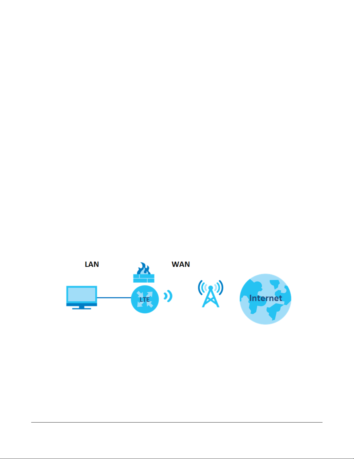
1.2.1 Internet Access
Your LTE7460-M608 provides shared Internet access by connecting to an LTE network. Computers can
connect to the LTE7460-M608’s PoE injector.
Figure 1 LTE7460-M608’s Internet Access Application
1.3 Ways to Manage the LTE7460-M608
Use the following method to manage the LTE7460-M608.
• Web Configurator. This is recommended for everyday management of the LTE7460-M608 using a
(supported) web browser.
LTE7460-M608 User’s Guide
9
Page 10
Chapter 1 Introduction
1.4 Good Habits for Managing the LTE7460-M608
Do the following things regularly to make the LTE7460-M608 more secure and to manage the LTE7460M608 more effectively.
• Change the password. Use a password that’s not easy to guess and that consists of different types of
characters, such as numbers and letters.
• Write down the password and put it in a safe place.
• Back up the configuration (and make sure you know how to restore it). Restoring an earlier working
configuration may be useful if the device becomes unstable or even crashes. If you forget your
password to access the Web Configurator, you will have to reset the LTE7460-M608 to its factory
default settings. If you backed up an earlier configuration file, you would not have to totally reconfigure the LTE7460-M608. You could simply restore your last configuration. Write down any
information your ISP provides you.
1.5 LEDs (Lights)
The LED color in your LTE7460-M608 indicates the signal quality. The following table describes the LEDs in
your LTE7460-M608.
Note: In the following the table the LED status On, Off, Flashing and Blinking are shown.
Flashing describes a LED that turns on and off every second, whereas Blinking describes
a LED that turns on and off every .4 seconds.
Table 1 LED Descriptions
LED 1 LED 2 LED 3 COLOR DESCRIPTION
Off Off Off Green The LTE7460-M608’s power is off.
Flashing Flashing Flashing Green The LTE7460-M608 is restoring to factory default when all three
are blinking.
Blinking Off Off Green The LTE7460-M608’s power is on but there is no Internet
connectivity.
Off Blinking Off Green The LTE7460-M608 is upgrading its firmware.
On On On Green The RSSI/RSRP(2G/3G/4G) is greater or equal to -80dBm. The
On On Blinking Green The RSSI/RSRP(2G/3G/4G) is greater or equal to -80dBm. The
On On Off Green The RSSI/RSRP (2G/3G/4G) is between -100dBm and -80dBm.
On On Flashing Green The RSSI/RSRP (2G/3G/4G) is between -100dBm and -80dBm.
On Off Off Green The LTE7460-M608 has the lowest signal strength. The RSSI/
On Off Flashing Green The LTE7460-M608 has the lowest signal strength. The RSSI/
LTE7460-M608 has the best signal strength, but there is no
Internet connectivity.
LTE7460-M608 has the best signal strength, and it has Internet
connectivity.
The LTE7460-M608 has a medium signal strength, but there is no
Internet connectivity.
The LTE7460-M608 has a medium signal strength, and it has
Internet connectivity.
RSRP(2G/3G/4G) lower than -100 dBm, but there is no Internet
connectivity.
RSRP(2G/3G/4G) lower than -100 dBm, and it has Internet
connectivity.
LTE7460-M608 User’s Guide
10
Page 11

2.1 Overview
The web configurator is an HTML-based management interface that allows easy device setup and
management via Internet browser. Use Internet Explorer 11.0 and later versions, Chrome 52 and later
versions, Mozilla Firefox 47 and later versions, or Safari 8.0 and later versions. The recommended screen
resolution is 1024 by 768 pixels.
In order to use the web configurator you need to allow:
• Web browser pop-up windows from your device. Web pop-up blocking is enabled by default in
Windows XP SP (Service Pack) 2.
• JavaScript (enabled by default).
• Java permissions (enabled by default).
CHAPTER 2
Introducing the Web
Configurator
2.1.1 Login Accounts
There is one system account that you can use to log in to the LTE7460-M608: “admin”. The admin
account allows you full access to all system configurations. The default admin user is “admin” and the
default password is “1234”.
2.1.2 Accessing the Web Configurator
1 Make sure your LTE7460-M608 hardware is properly connected (refer to the Quick Start Guide).
2 Launch your web browser.
3 Type "https://192.168.1.1" as the URL.
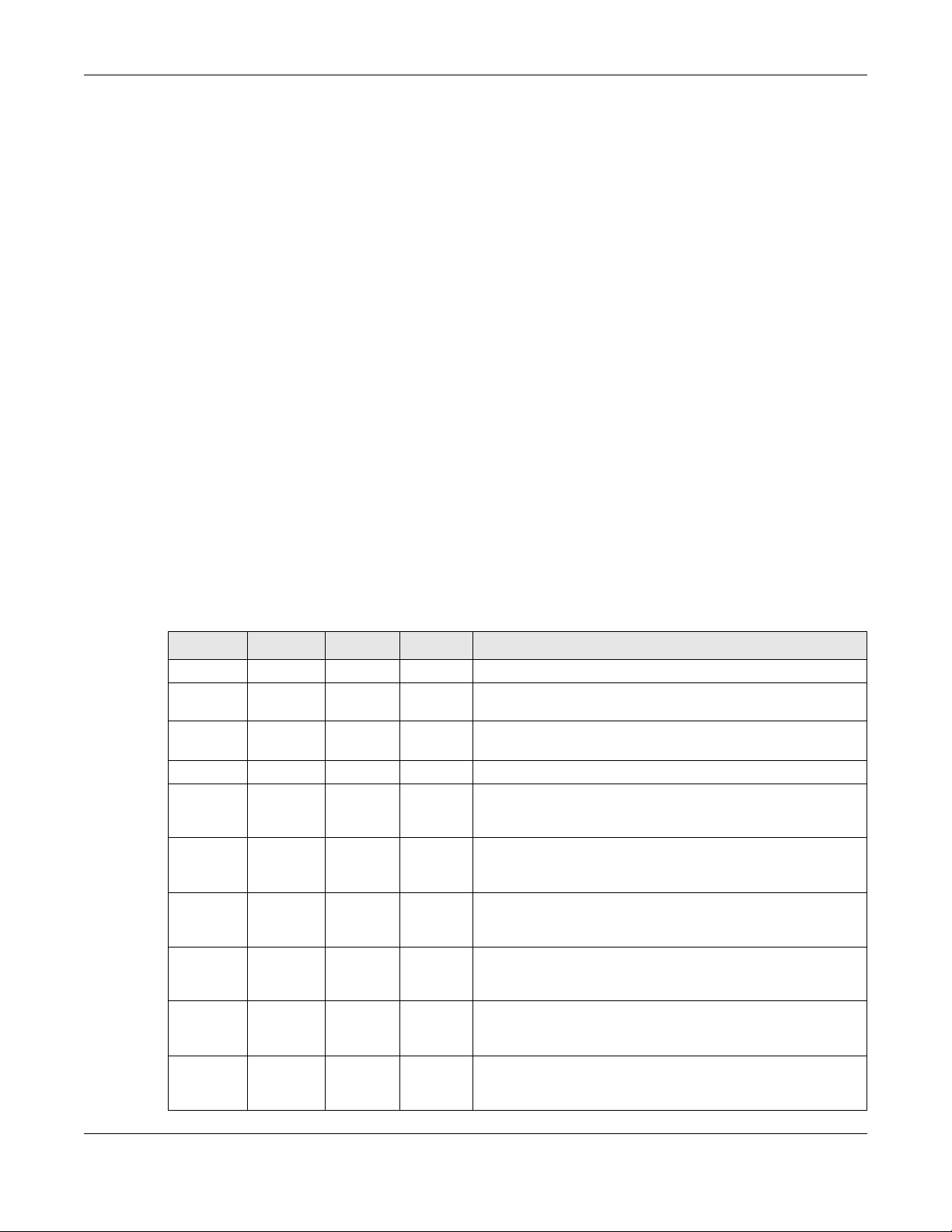
4 A password screen displays. Type “admin” as the default Username and “1234” as the default password
to access the device’s Web Configurator. Click Login. If you have changed the password, enter your
password and click Login.
LTE7460-M608 User’s Guide
11
Page 12
Chapter 2 Introducing the Web Configurator
Figure 2 Password Screen
Note: For security reasons, the LTE7460-M608 automatically logs you out if you do not use the
web configurator for five minutes (default). If this happens, log in again.
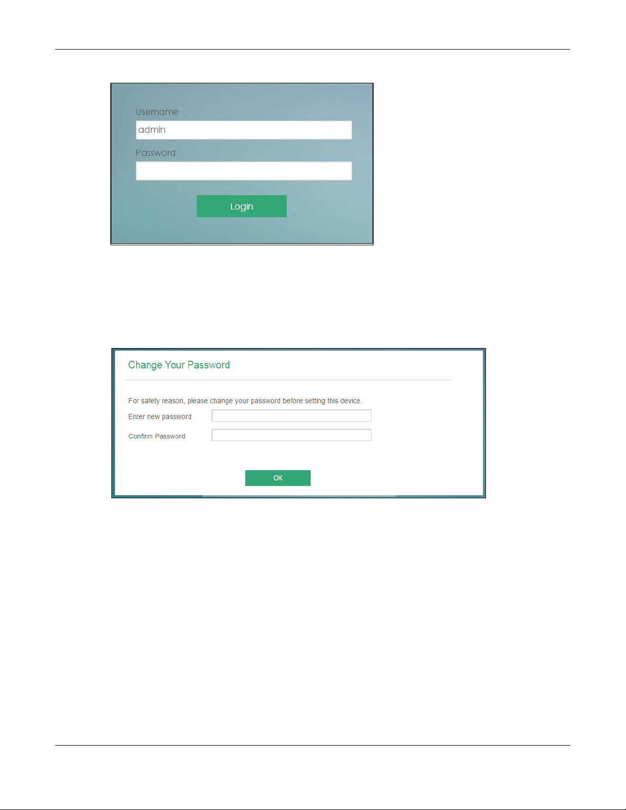
5 The following screen displays if you have not yet changed your password. It is required for you to enter a
new password, this password must contain between 8 and 30 ASCII characters, and should include at
least one numeric, capital and lower case character. Retype it to confirm and click OK.
Figure 3 Change Password Screen
6 The Home screen appears.
LTE7460-M608 User’s Guide
12
Page 13
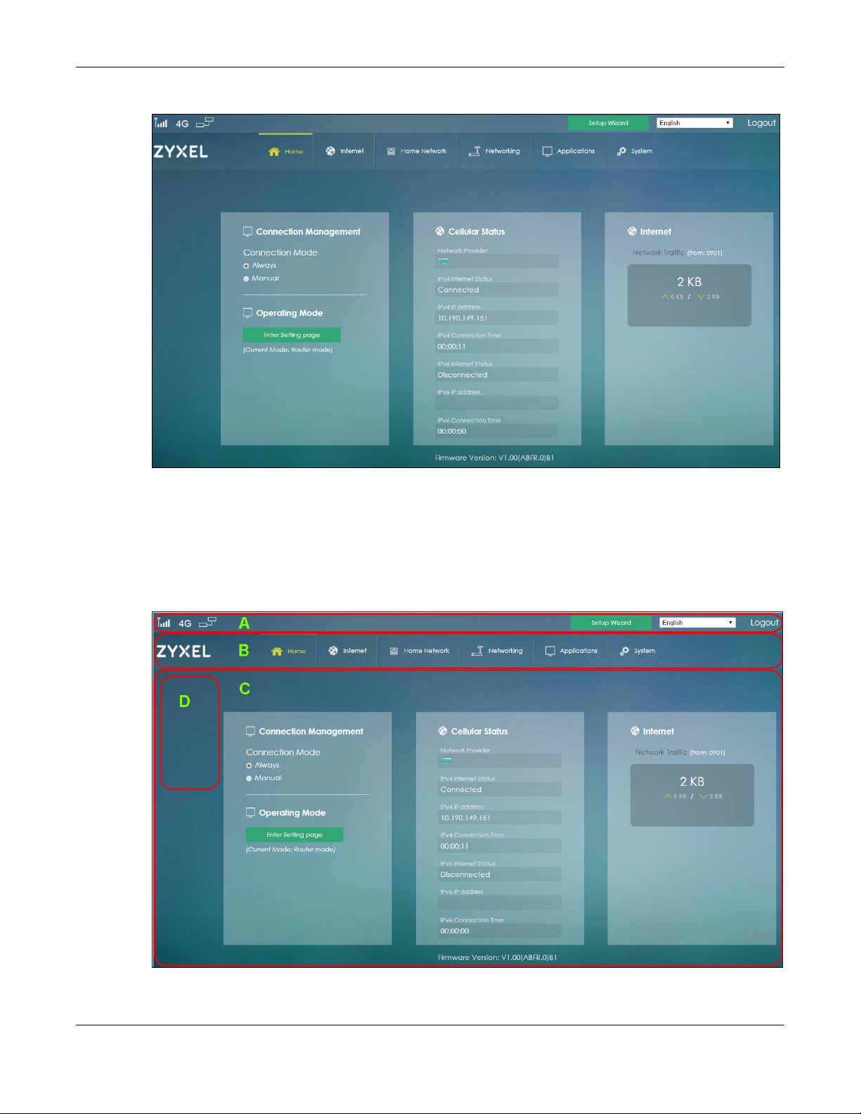
Figure 4 Home
Chapter 2 Introducing the Web Configurator
2.2 Navigating the Web Configurator
After logging in the Home screen will appear.
Figure 5 Web Configurator Layout
As illustrated above, the main screen is divided into these parts:
LTE7460-M608 User’s Guide
13
Page 14
• A - Title Bar
• B - Navigation Panel - Main Menus
• C - Main Window
• D - Navigation Panel - Sub Menus
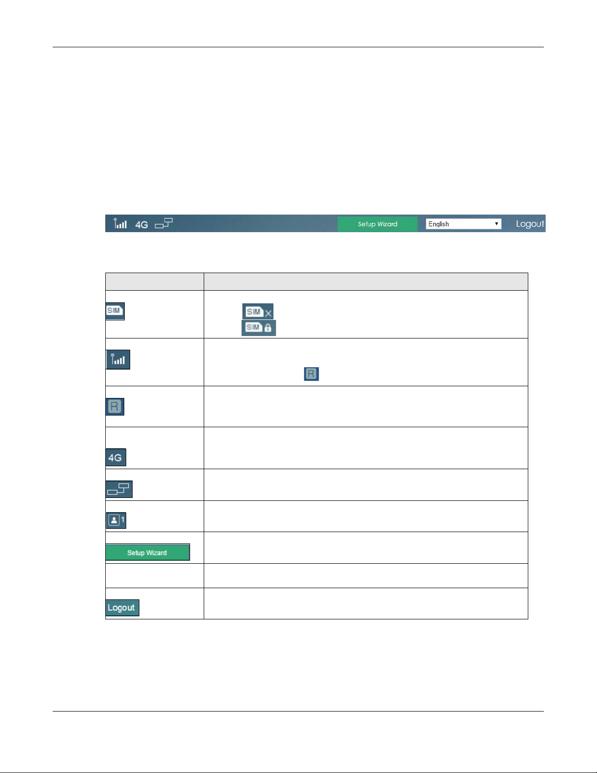
2.2.1 Title Bar
The title bar provides some useful links that always appear over the screens below, regardless of how
deep into the Web Configurator you navigate.
Figure 6 Title Bar
The icons in the title bar provide the following instructions.
Table 2 Title Bar: Web Configurator Icons
LABEL DESCRIPTION
SIM This shows whether a SIM card is inserted in the LTE7460-M608.
Signal Strength This shows the current signal strength to the mobile network.
Chapter 2 Introducing the Web Configurator
The icon shows if there is no SIM card inserted.
The icon shows if the SIM card is locked.
The icon is grayed out if the mobile data connection is not up.
Roaming This shows whether the LTE7460-M608 is connected to another service provider’s
Radio Access
Technology (RAT)
Internet This shows whether the LTE7460-M608 has an Internet connection.
LAN This shows the LTE7460-M608’s number of connected LAN clients.
Setup Wizard Click this to access the LTE7460-M608 easy setup.
Language Choose your language from the drop-down list on the upper right corner of the title
Logout Click this to log out of the Web Configurator.
2.2.2 Navigation Panel
This icon is replaced with if the LTE7460-M608 is using roaming.
mobile network using roaming.
The icon is grayed out if roaming is disabled on the LTE7460-M608.
This shows the Radio Access Techonology (RAT) of the network to which the LTE7460M608 is connected.
This shows Searching... if the LTE7460-M608 is not connected to a mobile network yet.
The icon shows if the LTE7460-M608 is not connected to the Internet.
bar.
Use the menu items on the navigation panel to open screens to configure the LTE7460-M608 features.
The following sections introduce the LTE7460-M608’s navigation panel menus and their screens.
LTE7460-M608 User’s Guide
14
Page 15
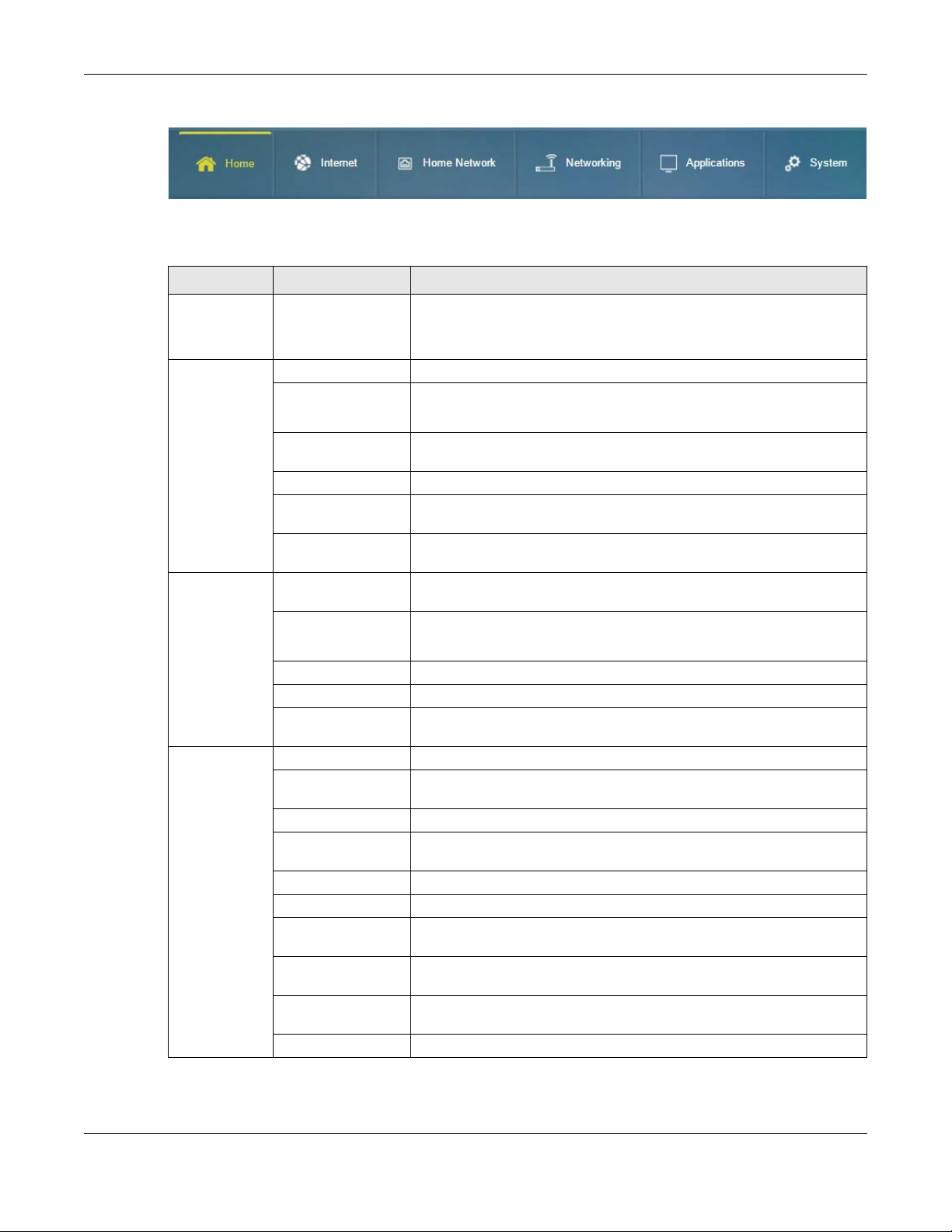
Chapter 2 Introducing the Web Configurator
Figure 7 Navigation Panel
The following table describes all the screens in the Web Configurator.
Table 3 Navigation Panel
MAIN MENU SUBMENU FUNCTION
Home Display connection mode, wireless LAN information and the LTE7460-
M608’s traffic statistics.
Use this screen to access the wizard.
Internet Internet Status Configure the WAN settings on the LTE7460-M608 for Internet access.
Internet Settings Use this to enable data roaming on the LTE7460-M608.
Select when and the type of network to which you want to connect.
PIN Settings Configure the PIN code when PIN code authentication is enabled.
Change the PIN code for the inserted SIM card.
APN Configuration Configure user-defined connection profiles.
Network Selection Display available Public Land Mobile Networks and select a preferred
network for roaming.
Data Usage/ Statistic Specify limiting the amount of the package data and view the LTE7460-
Home Network LAN IP Configure the management IP address for the LTE7460-M608 LAN
DHCP Enable the DHCP server on the LTE7460-M608.
Static Route Use this to add up to 15 static routes on the LTE7460-M608.
UPnP Enable the UPnP settings on the LTE7460-M608.
Connected Devices View current clients information of network clients connected to the
Networking Operating Mode Use this to choose the operating mode for your LTE7460-M608.
TR069 Configure TR069 for an administator to use an Auto Configuration Server
DNS Settings Configure the DNS settings on the LTE7460-M608.
Firewall Configure IPv4/Port, IPv6/Port, URL filtering rules, DoS attack, ALG, ULG,
DDNS Settings Configure the Dynamic DNS settings on the LTE7460-M608.
VPN Pass Through Use this to allow computers to establish an outbound VPN service.
Certificate
Management
Bandwidth
Management
Remote
Management
ICMP Use this screen to enable WAN and LAN ping respond.
M608’s traffic statistics.
interface.
Configure static DHCP series.
LTE7460-M608.
(ACS) to manage the LTE7460-M608.
and IP port forwarding rules.
Use this to upload and download certificate files to authenticate servers
and clients in your network.
Use this to control traffic on your LTE7460-M608.
Use this to allow addresses outside your LAN to access the LTE7460-M608.
LTE7460-M608 User’s Guide
15
Page 16
Chapter 2 Introducing the Web Configurator
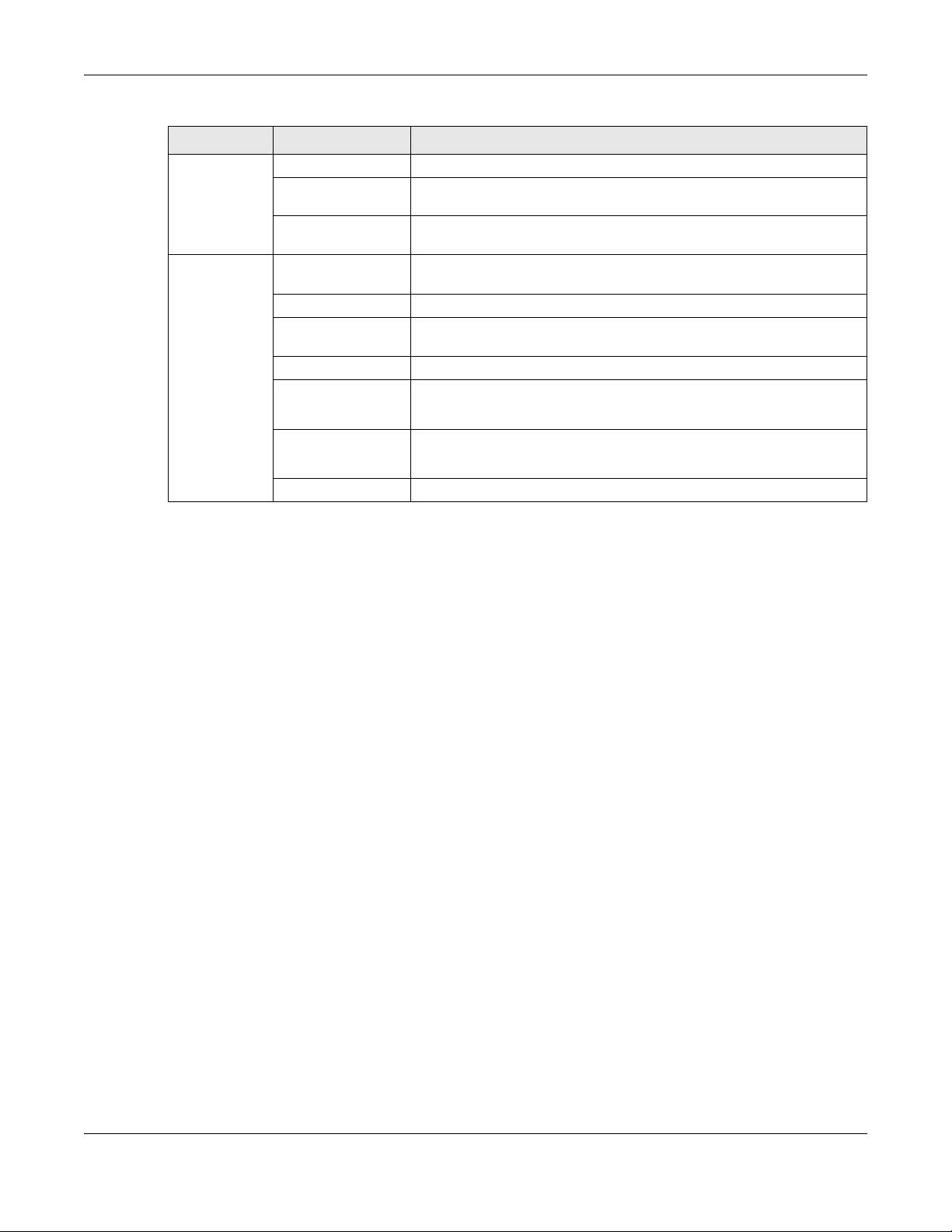
Table 3 Navigation Panel
MAIN MENU SUBMENU FUNCTION
Applications Contacts Use this screen to add, import or view the contacts stored in your SIM card.
Short Message Use this screen to send SMS messages through the service provider the
LTE7460-M608 uses.
USSD Use this to enter a code for devices in your network to communicate with
cellular telephones in your services provider’s network.
System System Information Display the LTE7460-M608’s basic information and reboot the LTE7460-
User Account Change administrative settings and the password of your LTE7460-M608.
Settings Profile Backup and restore device configurations or reset your device settings
Firmware Upgrade Upload a new firmware to the LTE7460-M608.
Time Settings Change the LTE7460-M608’s time.
System Log Configure to where the LTE7460-M608 is to send logs.
Diagnostic Use this screen to perform ping and trace route tests.
M608.
back to the factory default.
Select your time zone and configure daylight saving time.
View the logged messages.
LTE7460-M608 User’s Guide
16
Page 17

3.1 Overview
This chapter shows you how to use the LTE7460-M608’s various features.
• Connecting to the Internet, see page 17
• Configuring DHCP, see page 17.
• Configuring Static Route for Routing to Another Network, see page 19.
• Access the LTE7460-M608 Using DDNS, see page 20.
3.2 Connecting to the Internet
CHAPTER 3
Tutorials
This section gives you an example on how to connect to the Internet.
1 Insert the SIM Card into your LTE7460-M608 SIM slot. Make sure this SIM has an active data plan with your
Internet Service Provider (ISP).
2 Connect your LTE7460-M608 to your computer, and log into the Web Configurator.
3 If your SIM has a PIN Code, enter this code in the Home > Internet screen.
4 Use the Home screen or WAN > Internet Status screen to check the Internet Status (IPv4) or Internet Status
(IPv6). If it shows Connected this means your internet connection is up.
3.3 Configuring DHCP
You can enable the DHCP(Dynamic Host Configuration Protocol) in your LTE7460-M608 to assign IP
addresses and DNS servers to systems that support DHCP client capability. DHCPallows clients to obtain
TCP/IP configuration at start-up from a server.
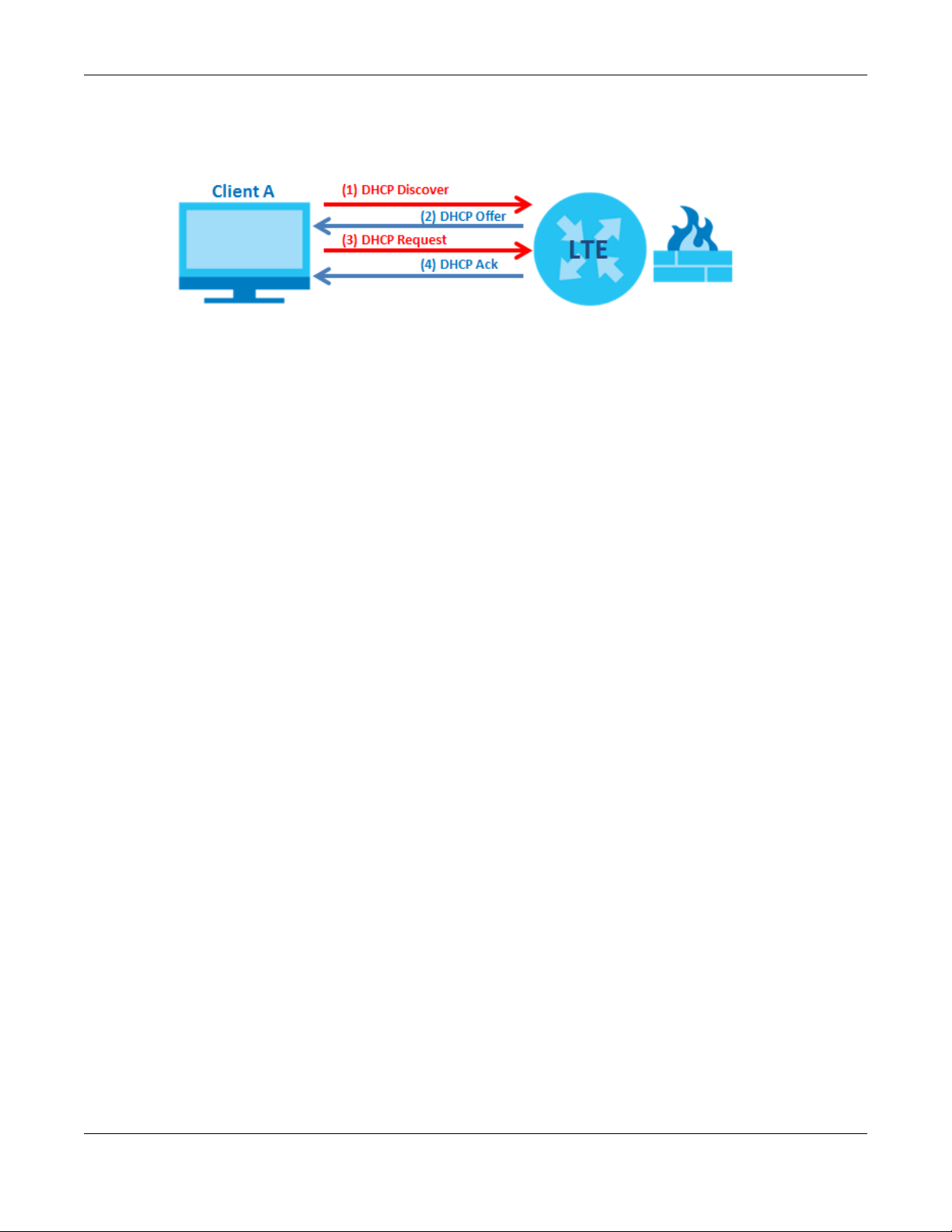
The following figure shows how Client A uses DHCP to join the LTE7460-M608’s network. First Client A
searches for an available DHCP, and sends a DHCP Discover broadcast message asking for an IP
address to connect to. Then the DHCP selects an IP address from its pool of IP addresses for Client A. The
DHCP sends a DHCP Offer including the IP address selected and a lease time, which is the period of time
Client A will be able to use this IP address, After Client A has received DHCP offers for an IP address, it
chooses one and sends out a DHCP Request including the IP address it chose. Finally the DHCP confirms
LTE7460-M608 User’s Guide
17
Page 18
Chapter 3 Tutorials
through a DHCP Ack (Acknowledge) message that the host can use the IP address for the previously
specified lease time.
To configure the DHCP in your LTE7460-M608:
1 Log into the LTE7460-M608’s Web Configurator.
2 Click Home Network > DHCP > DHCP Settings.
3 Click Enable DHCP Server.
4 Enter a range of addresses from which your DHCP will assign to devices in your network.
Note: Do not include the LTE7460-M608’s LAN IP address in your range of addresses.
5 Enter the Lease Time, the period of time (in minutes) a device can use one of the IP addresses from the
DHCP pool. The lease time helps recycle unused IP addresses so that other can use them again.
3.3.1 Adding Devices to Your Static DHCP List
IP addresses from the DHCP pool can be reused after they have completed their lease time. Add your
devices to your Static DHCP List so they have the same IP address everytime they connect to your
network.
To add a device to your Static DHCP List:
1 Log into the LTE7460-M608’s Web Configurator.
2 Click Home Network > DHCP > Static DHCP List.
3 Click Add New.
4 Enter the IP address you want to assign to your device.
5 Enter the MAC Address of your device to which the LTE7460 assigns the IP address.
LTE7460-M608 User’s Guide
18
Page 19
Chapter 3 Tutorials
3.4 Configuring Static Route for Routing to Another Network
In order to extend your Intranet and control traffic flowing directions, you may connect a router to the
LTE7460-M608’s LAN. The router may be used to separate two area networks. This tutorial shows how to
configure a static routing rule for two network routings.
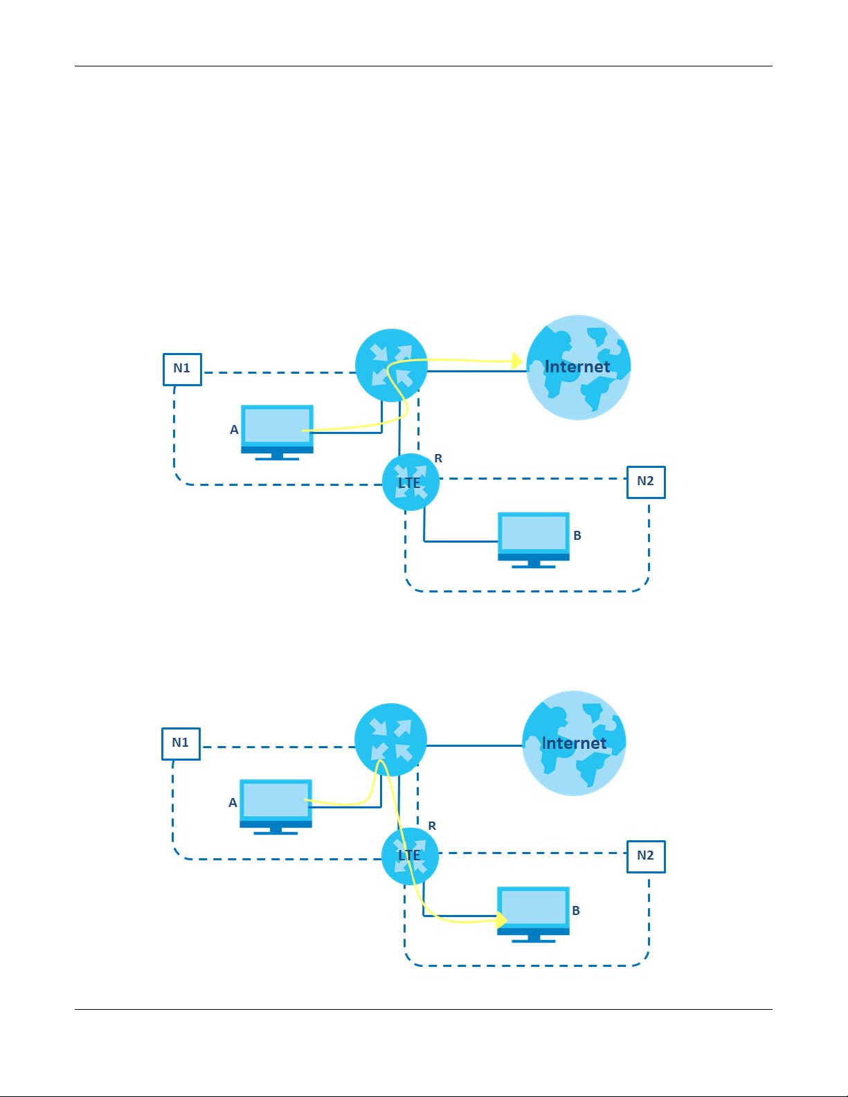
In the following figure, router R is connected to the LTE7460-M608’s LAN. R connects to two networks, N1
(192.168.1.x/24) and N2 (192.168.10.x/24). If you want to send traffic from computer A (in N1 network) to
computer B (in N2 network), the traffic is sent to the LTE7460-M608’s WAN default gateway by default. In
this case, B will never receive the traffic.
You need to specify a static routing rule on the LTE7460-M608 to specify R as the router in charge of
forwarding traffic to N2. In this case, the LTE7460-M608 routes traffic from A to R and then R routes the
traffic to B.
LTE7460-M608 User’s Guide
19
Page 20
Chapter 3 Tutorials
This tutorial uses the following example IP settings:
Table 4 IP Settings in this Tutorial
DEVICE / COMPUTER IP ADDRESS
The LTE7460-M608’s LAN 192.168.1.1
A 192.168.1.34
R’s N1 192.168.1.253
R’s N2 192.168.10.2
B 192.168.10.33
To configure a static route to route traffic from N1 to N2:
1 Log into the LTE7460-M608’s Web Configurator.
2 Click Home Network > Static Route.
3 Click Add new in the Static Route screen.
4 Configure the Static Route Setup screen using the following settings:
4a Type 192.168.10.2 and subnet mask 255.255.255.0 for the destination, N2.
4b Type 192.168.1.253 (R’s N1 address) in the Gateway IP Address field.
4c Click Add.
Now B should be able to receive traffic from A. You may need to additionally configure B’s firewall
settings to allow specific traffic to pass through.
3.5 Access the LTE7460-M608 Using DDNS
If you connect your LTE7460-M608 to the Internet and it uses a dynamic WAN IP address, it is
inconvenient for you to manage the device from the Internet. The LTE7460-M608’s WAN IP address
changes dynamically. Dynamic DNS (DDNS) allows you to access the LTE7460-M608 using a domain
name.
To use this feature, you have to apply for DDNS service at www.dyndns.org.
This tutorial covers:
LTE7460-M608 User’s Guide
20
Page 21
Chapter 3 Tutorials
• Registering a DDNS Account on www.dyndns.org
• Configuring DDNS on Your LTE7460-M608
• Testing the DDNS Setting
Note: If you have a private WAN IP address, then you cannot use DDNS.
3.5.1 Registering a DDNS Account on www.dyndns.org
1 Open a browser and type http://www.dyndns.org.
2 Apply for a user account. This tutorial uses UserName1 and 12345 as the username and password.
3 Log into www.dyndns.org using your account.
4 Add a new DDNS host name. This tutorial uses the following settings as an example.
• Hostname: zyxelrouter.dyndns.org
• Service Type: Host with IP address
• IP Address: Enter the WAN IP address that your LTE7460-M608 is currently using. You can find the IP
address on the LTE7460-M608’s Web Configurator Home page.
5 Then you will need to configure the same account and host name on the LTE7460-M608 later.
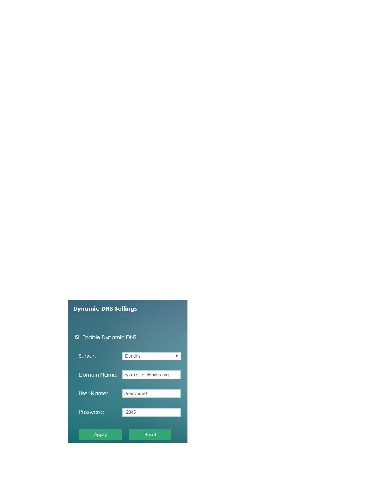
3.5.2 Configuring DDNS on Your LTE7460-M608
Configure the following settings in the Networking > DDNS Settings screen.
• Select Enable Dynamic DNS.
• Select www.DynDNS.com as the service provider.
• Type zyxelrouter.dyndns.org in the Host Name field.
• Enter the user name (UserName1) and password (12345).
LTE7460-M608 User’s Guide
21
Page 22

Click Apply.
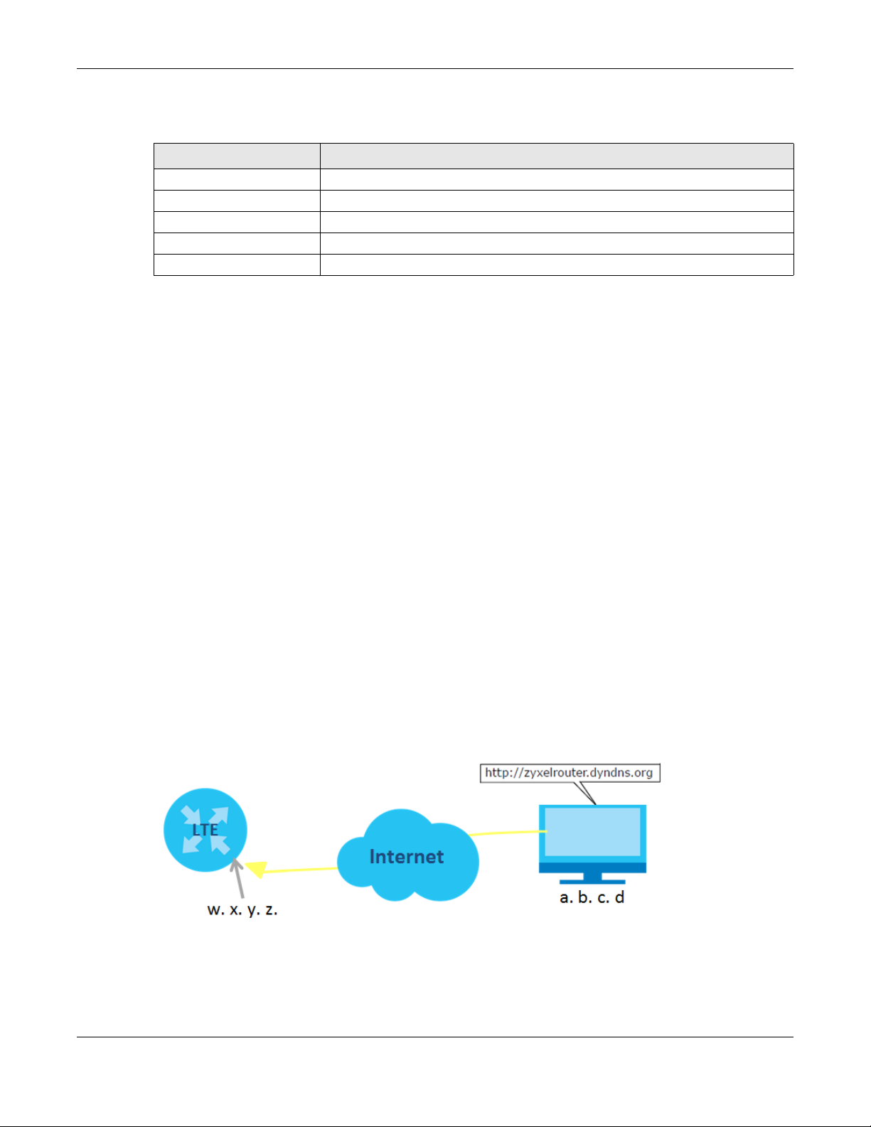
3.5.3 Testing the DDNS Settings
Now you should be able to access the LTE7460-M608 from the Internet. To test this:
1 Open a web browser on the computer (using the IP address a.b.c.d) that is connected to the Internet.
2 Type http://zyxelrouter.dyndns.org and press [Enter].
3 The LTE7460-M608’s login page should appear. You can then log into the LTE7460-M608 and manage it.
Chapter 3 Tutorials
LTE7460-M608 User’s Guide
22
Page 23

PART II
Technical Reference
23
Page 24
4.1 Overview
Use the Home screen to check status information about the LTE7460-M608. Use the Wizard screen to
configure the LTE7460-M608’s basic Internet access and wireless settings.
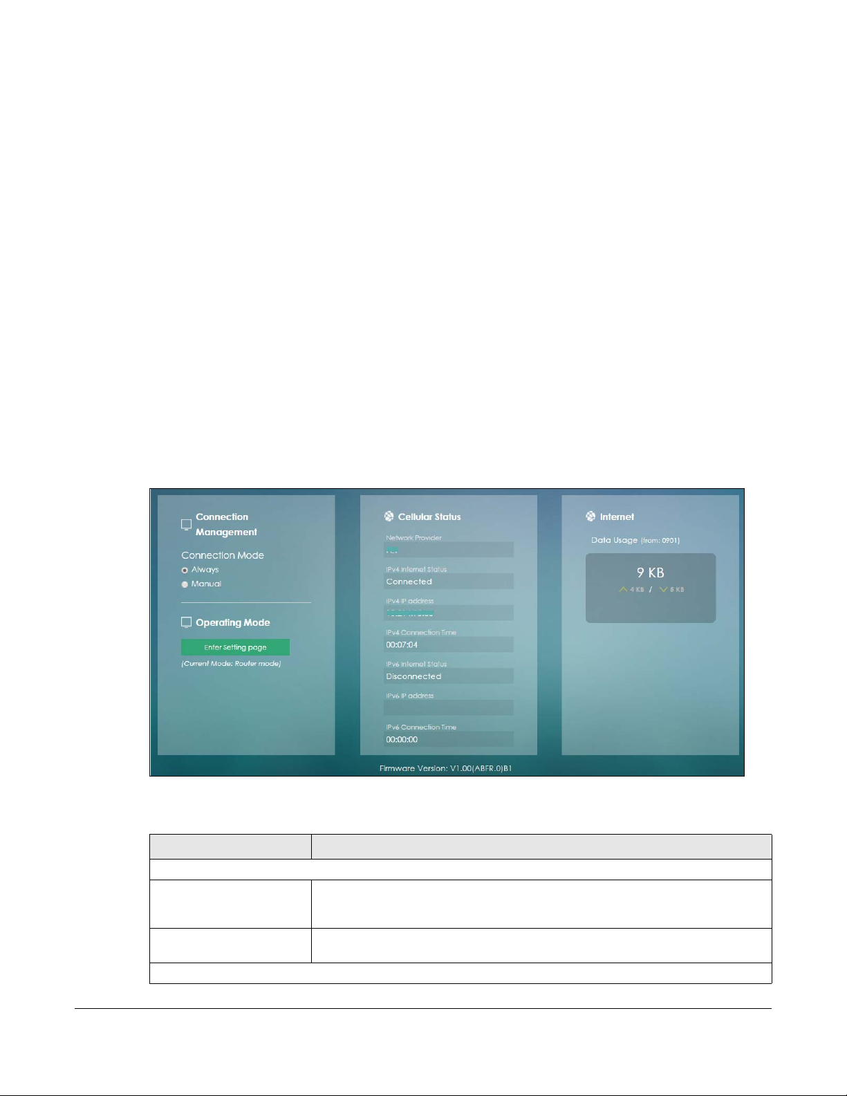
4.2 Home Screen
This screen is the first thing you see when you log into the LTE7460-M608. It also appears every time you
click the Home icon in the navigation panel. The Home screen displays the LTE7460-M608’s connection
mode, wireless LAN information and traffic statistics.
Figure 8 Home
CHAPTER 4
Home
The following table describes the labels in this screen.
Table 5 Home
LABEL DESCRIPTION
Connection Management
Connection Mode This field displays the connected mode of the LTE7460-M608. Select Always to
Operating Mode Click the Enter Setting page button to set up the operating mode for your LTE7460-
Cellular Status
connect to the mobile network automatically if there is an available mobile
network. Otherwise, select Manual.
M608.
LTE7460-M608 User’s Guide
24
Page 25
Chapter 4 Home
Table 5 Home
LABEL DESCRIPTION
Network Provider This field displays the name of the network provider.
IPv4 Internet Status This field displays Connected if the LTE7460-M608 has IPv4 Internet. It displays
Disconnected if there is no Internet connection through IPv4 Internet.
IPv4 IP address This field displays the IPv4 IP address your LTE7460-M608 uses to access the Internet.
IPv4 Connection Time This field displays the time your LTE7460-M608 IPv4 connection to the Internet has
been up.
IPv6 Internet Status This field displays Connected if the LTE7460-M608 has IPv6 Internet. It displays
IPv6 IP address This field displays the IPv6 IP address your LTE7460-M608 uses to access the Internet.
IPv6 Connection Time This field displays the time your LTE7460-M608 IPv6 connection to the Internet has
Internet
Data Usage This field displays the amount of downstream and upstream in kilobytes (KB) used in
Disconnected if there is no Internet connection through IPv6 Internet.
Note: This information will not be displayed if your ISP does not support IPv6
Internet protocol.
been up.
the LTE7460-M608’s LAN.
Firmware Version This field displays the LTE7460-M608’s current firmware version.
4.3 Setup Wizard
Click Home > Setup Wizard to open the wizard screen.
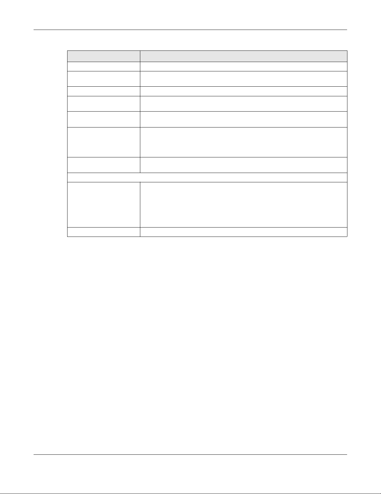
4.3.1 Operating Mode
The LTE7460-M608 offers two different system operation modes: Router Mode and Bridge Mode. When
you click on Setup Wizard the following screen opens. To learn more about each mode see Section 7.2
on page 59.
Note: This information will not be displayed if you have not entered
the SIM’s PIN code. Enter the PIN code here before it is
available for data usage.
LTE7460-M608 User’s Guide
25
Page 26
Chapter 4 Home
Figure 9 Setup Wizard: Set Up Operating Mode
4.3.2 Internet
Select the Auto option for the LTE7460-M608 to use any of the available mobile networks. Select Allow
Data Roaming to use your device in an area which is not covered by your service provider. Click Next to
continue.
Figure 10 Setup Wizard > Set Up Internet: Internet Settings
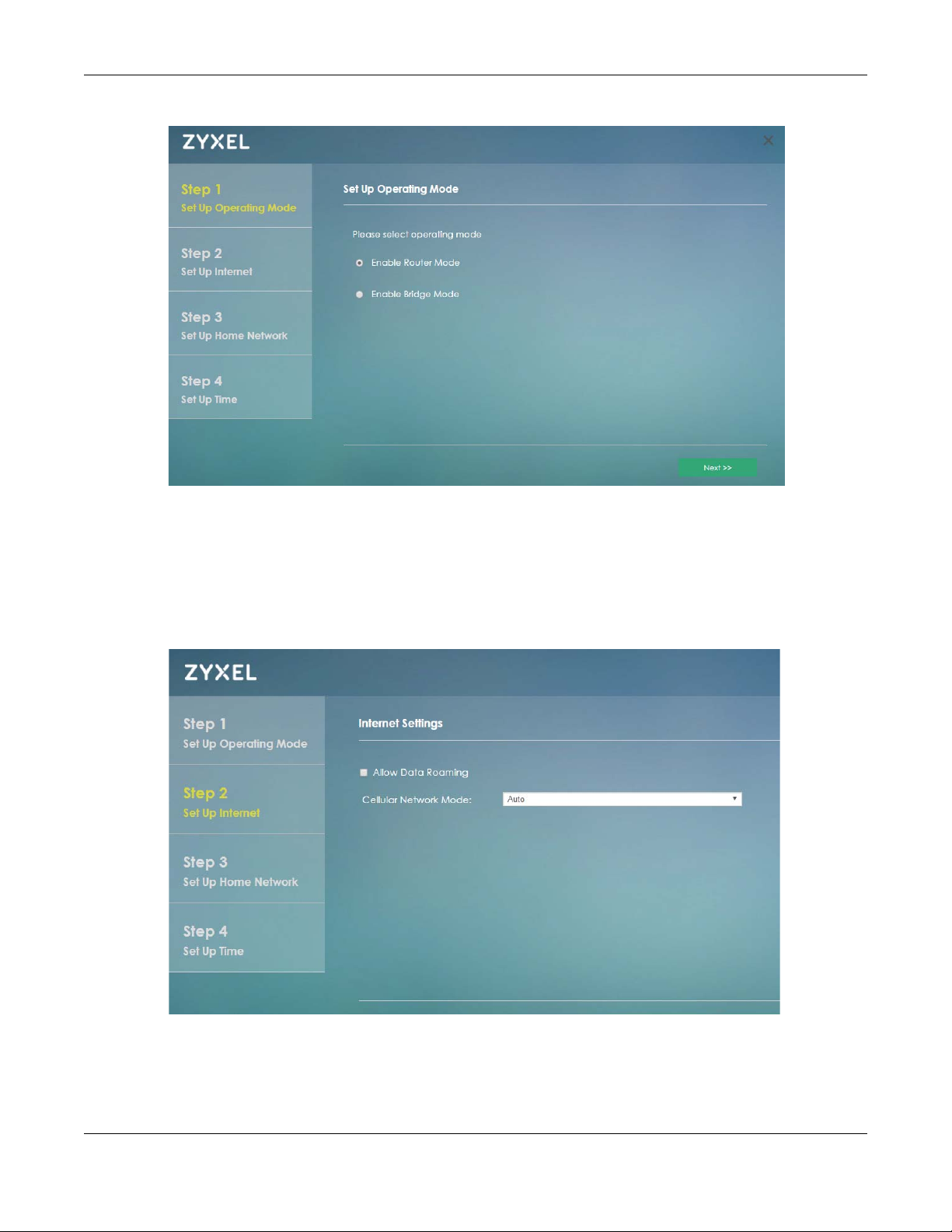
Select Auto option if you did not configure the connection profile. Click Next to continue.
LTE7460-M608 User’s Guide
26
Page 27
Chapter 4 Home
Figure 11 Setup Wizard > Set Up Internet: APN Profile
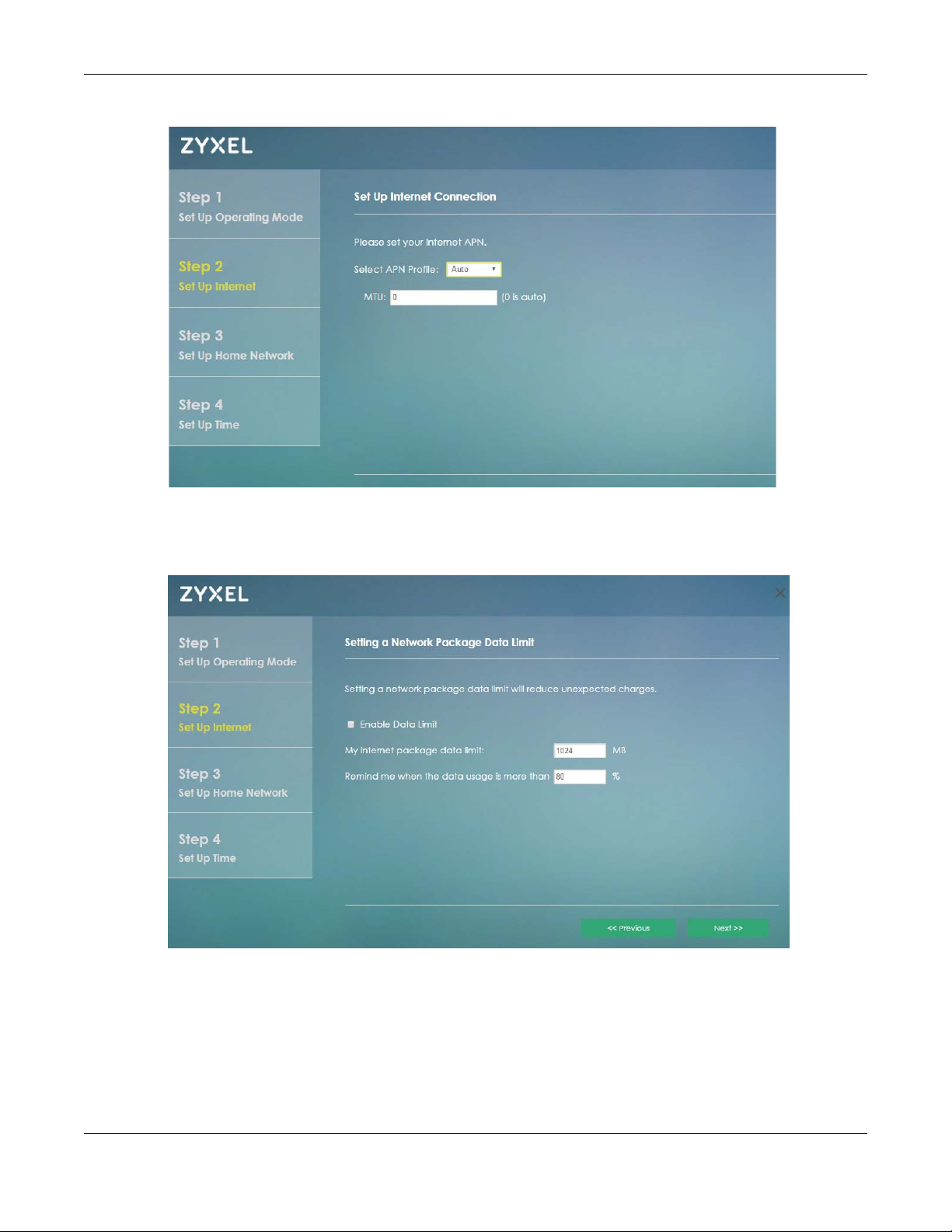
Specify limiting the amount of the data package and reminding the percentage of the data package
usage. Click Next to configure Wi-Fi settings.
Figure 12 Setup Wizard > Set Up Internet: Package Data Limit
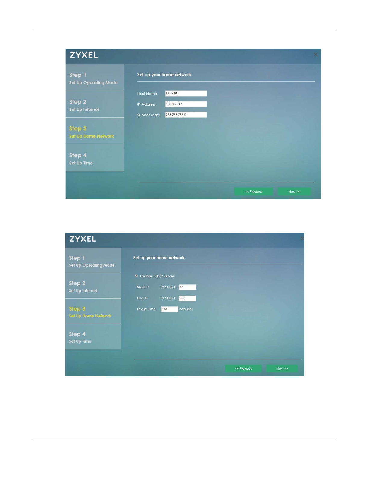
4.3.3 Home Network
Use this screen to assign a name to your LTE7460-M608 network and modify its IP Address and Subnet
Mask. Click Next to continue.
LTE7460-M608 User’s Guide
27
Page 28
Chapter 4 Home
Figure 13 Setup Wizard > Set Up Home Network
Enable the DHCP Server and add a range of IP addresses that can access your LTE7460-M608 for a
determined period of time (Lease Time). Click Next to continue.
Figure 14 Setup Wizard > Set Up Home Network: DHCP Server
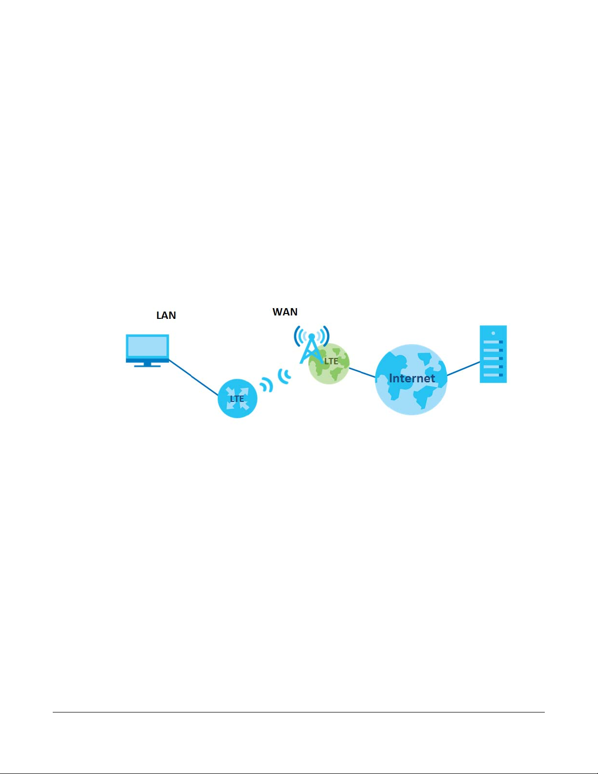
4.3.4 Time
Select the LTE7460-M608’s time zone and modify any Network Time Protocol (NTP) servers so your
LTE7460-M608 can obtain its time from these servers.
LTE7460-M608 User’s Guide
28
Page 29
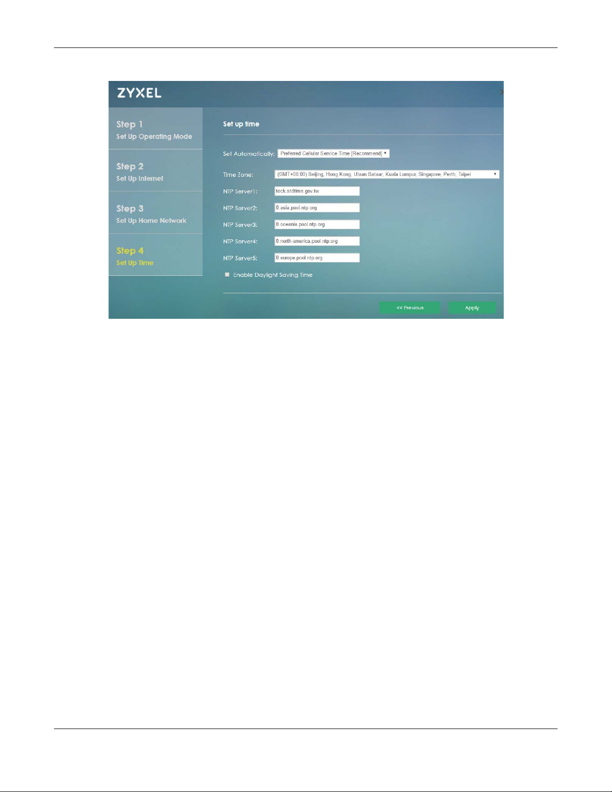
Figure 15 Setup Wizard > Set Up Time
Chapter 4 Home
Click Apply to save your changes. The LTE7460-M608 will restart.
LTE7460-M608 User’s Guide
29
Page 30
5.1 Overview
This chapter discusses the LTE7460-M608’s Internet screens. Use these screens to configure your LTE7460M608 for Internet access.
A WAN (Wide Area Network) connection is an outside connection to another network or the Internet. It
connects your private networks, such as a LAN (Local Area Network) and other networks, so that a
computer in one location can communicate with computers in other locations.
Figure 16 LAN and WAN
CHAPTER 5
Internet
5.1.1 What You Can Do in this Chapter
• Use the Internet Status screen to display the LTE7460-M608’s WAN status and details about the
Network Provider (Section 5.2 on page 31).
• Use the Internet Settings screen to configure the WAN settings on the LTE7460-M608 for Internet access
(Section 5.3 on page 33).
• Use the PIN Settings screen to enable or disable PIN code authentication (Section 5.4 on page 33).
• Use the APN Configuration screen to configure user-defined connection profiles (Section 5.5 on page
34).
• Use the Network Selection screen to display available Public Land Mobile Networks (Section 5.6 on
page 36).
• Use the Data Usage/Statistic screen to specify limiting the amount of the data package and view the
LTE7460-M608’s traffic statistics (Section 5.7 on page 38).
5.1.2 What You Need to Know
The following terms and concepts may help as you read this chapter.
LTE7460-M608 User’s Guide
30
Page 31

Chapter 5 Internet
WAN IP Address
The WAN IP address is an IP address for the LTE7460-M608, which makes it accessible from an outside
network. It is used by the LTE7460-M608 to communicate with other devices in other networks. The ISP
dynamically assigns it each time the LTE7460-M608 tries to access the Internet.
APN
Access Point Name (APN) is a unique string which indicates an LTE network. An APN is required for LTE
stations to enter the LTE network and then the Internet.
5.1.3 Before You Begin
You may need to know your Internet access settings such as LTE APN and SIM card’s PIN code if the
INTERNET light on your LTE7460-M608 is off. Get this information from your service provider.
5.2 Internet Status Screen
Use this screen to view details about your LTE7460-M608’s connection with the Internet Service Provider
(ISP). Click Internet > Internet Status. The screen appears as shown next.
Figure 17 Internet > Internet Status
LTE7460-M608 User’s Guide
31
Page 32

Chapter 5 Internet
The following table describes the labels in this screen.
Table 6 Internet > Internet Status
LABEL DESCRIPTION
Internet Status
Internet Status (IPv4) This shows the IPv4 mobile data connection status.
IP Address (IPv4) This field displays the current IPv4 address assigned to the WAN interface.
Connection Time (IPv4) This field displays how long you connect to the Internet through IPv4.
Internet Status (IPv6) This shows the IPv6 mobile data connection status.
IP Address (IPv6) This field displays the current IPv6 address assigned to the WAN interface.
Connection Time (IPv6) This field displays how long you connect to the Internet through IPv6.
Advanced Internet Information
Network Provider This shows the name of the service provider for the mobile network to which the
Network Type This shows the mobile network type (such as LTE, UMTS, GSM, HSPA+, etc.) to which
MCC This displays the Mobile Country Code (MCC), which is used to identify the country
MNC This displays the Mobile Network Code (MNC), which is used in combination with
Band This displays the network type and the frequency band used by the mobile network
EARFCN/UARFCN/ARFCN This displays the channel used by the mobile network to which the LTE7460-M608 is
LAC This displays the 2-octet Location Area Code (LAC), which is used to identify a
TAC This displays the Tracking Area Code (TAC), which is used to identify the country of a
CID This displays the Cell ID (CID), which is a unique number used to identify the Base
Ec/Io This displays the ratio (in dB) of the received energy per chip and the interference
PCI This shows the Physical Cell ID(PCI), which are queries and replies among the
RSCP This displays the Received Signal Code Power (RSCP) which measures the power on
RSRP This displays the Reference Signal Receive Power (RSRP), which is the average
RSRQ This displays the Reference Signal Received Quality (RSRQ), which is the ratio of RSRP
SNR This displays the Signal-to-Noise-Ratio (SNR), which indicates a ratio of signal power
RSSI This displays the received signal strength indicator (RSSI), that is, the received signal
LTE7460-M608 is connected.
the LTE7460-M608 is connecting.
of a mobile subscriber.
MCC to identify the public land mobile network (PLMN) of a mobile subscriber.
to which the LTE7460-M608 is connecting.
connecting.
location area within a PLMN.
mobile subscriber.
Transceiver Station to which the LTE7460-M608 is connecting.
level.
LTE7460-M608 and the mobile network it is connecting to.
the channel used by the LTE7460-M608.
received power of all Resource Elements (RE) that carry cell-specific Reference
Signals (RS) within the specified bandwidth.
to the E-UTRA carrier RSSI and indicates the quality of the received reference signal.
to noise power.
strength in dBm.
LTE7460-M608 User’s Guide
32
Page 33

Chapter 5 Internet
5.3 Internet Settings Screen
Use this screen to change your LTE7460-M608’s Internet access settings. Click Internet > Internet Settings.
The screen appears as shown next.
Figure 18 Internet > Internet Settings
The following table describes the labels in this screen.
Table 7 Internet > Internet Settings
LABEL DESCRIPTION
Internet Settings
Allow Data Roaming Select this check box to enable data roaming on the LTE7460-M608.
Data roaming is to use your mobile device in an area which is not covered by your
local service provider. Enable data roaming to ensure that your LTE7460-M608 is kept
connected to the Internet when you are traveling outside the geographical
coverage area of the network to which you are registered.
Cellular Network Mode Select the type of the network (4G Mode, 3G Mode, or 2G Mode) to which you want
Internet Connection
Method
LTE Band Selection Select the LTE frequency bands provided by your ISP.
Apply Click Apply to save your changes back to the LTE7460-M608.
Reset Click Reset to reload the previous configuration for this screen.
the LTE7460-M608 to connect.
Otherwise, select Auto to have the LTE7460-M608 connect to an available network
using the default settings on the SIM card. If the currently registered mobile network
is not available or the mobile network’s signal strength is too low, the LTE7460-M608
switches to another available mobile network.
Select Always to connect to the mobile network automatically if there is an
available mobile network. Otherwise, select Manual.
5.4 PIN Settings Screen
Use this screen to turn on or off PIN code authentication on the inserted SIM Card. You can also change
your PIN code to prevent others from using your account should the SIM be stolen or removed from your
LTE7460-M608. Click Internet > PIN settings. The screen appears as shown next.
LTE7460-M608 User’s Guide
33
Page 34

Figure 19 Internet > PIN Settings
Chapter 5 Internet
The following table describes the labels in this screen.
Table 8 Internet > PIN Settings
LABEL DESCRIPTION
PIN Protection
Enable PIN Protection Click On to turn on PIN code authentication. Click Off to turn off PIN code
authentication.
A PIN (Personal Identification Number) code is a key to a SIM card. Without the PIN
code, you cannot use the SIM card.
Enable Save PIN Select this for the LTE7460-M608 to save the SIM card PIN code, and avoid reentering
the PIN code everytime you log in.
Change PIN Code
Current PIN Enter the default or existing PIN code for the inserted SIM card.
New PIN Configure a new PIN code for the SIM card. You can specify any four to eight digits
Confirm New PIN Enter the new PIN code again for confirmation.
Apply Click Apply to save your changes back to the LTE7460-M608.
Reset Click Reset to reload the previous configuration for this screen.
to have a new PIN code.
5.5 APN Configuration Screen
Use this screen to view or configure a connection profile. A connection profile defines the parameters
that you need to connect to a mobile network, such as the Access Point Name (APN), user name and
password. Click Internet > APN Configuration. The screen appears as shown next.
LTE7460-M608 User’s Guide
34
Page 35

Chapter 5 Internet
Figure 20 Internet > APN Configuration
The following table describes the labels in this screen.
Table 9 Internet > APN Configuration
LABEL DESCRIPTION
APN Configuration
Select APN Profile Select Auto to reload the default profile. Otherwise, select Manual to configure a
connection profile.
MTU Specify the Maximum Transmission Unit (MTU) for each packet or frame sent in the
LTE7460-M608’s network.
Apply Click Apply to save your changes back to the LTE7460-M608.
Reset Click Reset to reload the previous configuration for this screen.
2nd APN for TR069 Access Point Names (APNs) are provided by your service provider. Connections with
Enable 2nd APN Check to enable a second APN profile.
APN This field displays the Access Point Name (APN) in the profile.
different APNs may provide different services (such as Internet access or MMS (MultiMedia Messaging Service) and charging method.
You can include a second APN profile to allow TR069 services to go by the second
APN while the rest of the traffic goes by the first APN.
You can enter up to 30 printable characters [A-Z][a-z][-]. Spaces are not allowed.
LTE7460-M608 User’s Guide
35
Page 36

Chapter 5 Internet
Table 9 Internet > APN Configuration
LABEL DESCRIPTION
Authentication Select the type of authentication method peers use to connect to the LTE7460-M608
in LTE connections.
In Password Authentication Protocol (PAP) peers identify themselves with a user
name and a password. In Challenge Handshake Authentication Protocol (CHAP)
additionally to user names and passwords the LTE7460-M608 sends regular
challenges to make sure an intruder has not replaced a peer. Otherwise you can
select Auto or None.
Username This field displays the user name in the profile.
Type the user name (of up to 31 printable ASCII characters).
Password This field displays the password in the profile.
Type the password (of up to 31 printable ASCII characters) associated with the user
name above.
PDP type Choose the Packet Data Protocol (PDP) type provided by your Internet service
provider.
MTU Specify the Maximum Transmission Unit (MTU) for each packet or frame sent in the
LTE7460-M608’s network.
Apply Click Apply to save your changes back to the LTE7460-M608.
Reset Click Reset to reload the previous configuration for this screen.
5.6 Network Selection Screen
This screen allows you to view available Public Land Mobile Networks (PLMNs) and select your preferred
network when the LTE7460-M608 is outside the geographical coverage area of the network to which
you are registered and roaming is enabled.
Click Internet > Network Selection. The screen appears as shown next.
LTE7460-M608 User’s Guide
36
Page 37

Chapter 5 Internet
Figure 21 Internet > Network Selection
The following table describes the labels in this screen.
Table 10 Internet > Network Selection
LABEL DESCRIPTION
PLMN Mode
Select PLMN Mode Select Auto to have the LTE7460-M608 automatically connect to the first available
mobile network.
Selected Network Name This shows the ISP the LTE7460-M608 is currently connected to.
Selected Network Type This shows the type of network the LTE7460-M608 is using when connected to the ISP.
Scan Timestamp This shows the last time the LTE7460-M608 scanned for ISPs on its surroundings.
Check the radio button so the LTE7460-M608 connects to this ISP.
Status This shows Current to show the ISP the LTE7460-M608 is currently connected to.
This shows Forbidden to indicate the LTE7460-M608 can not connect to this ISP.
This shows Available to indicate an available ISP your LTE7460-M608 can connect to.
Network Name This shows the ISP name.
Network Type This shows the type of network the ISP provides.
Scan Click Scan for the LTE7460-M608 to check for available ISPs on its surroundings.
Apply Click Apply to save your changes back to the LTE7460-M608.
Reset Click Reset to reload the previous configuration for this screen.
LTE7460-M608 User’s Guide
37
Page 38

Chapter 5 Internet
5.7 Data Usage/Statistic Screen
This screen allows you to configure limiting the amount of the data package and view the LTE7460M608’s traffic statistics.
Click Internet > Data Usage/Statistic. The screen appears as shown next.
Figure 22 Internet > Data Usage/Statistic
The following table describes the labels in this screen.
Table 11 Internet > Data Usage/Statistic
LABEL DESCRIPTION
Package Data Limit Setting
Enable Data Limit Select the check box to enable data limits.
My internet package data
limit is
Specify the limiting the amount of the package data in this field.
LTE7460-M608 User’s Guide
38
Page 39

Chapter 5 Internet
Table 11 Internet > Data Usage/Statistic
LABEL DESCRIPTION
Remind me when data
usage is more than
Usage cycle reset date Specify the date that you want the LTE7460-M608 to restart calculating the amount
Apply Click Apply to save your changes back to the LTE7460-M608.
Reset Click Reset to reload the previous configuration for this screen.
Reset Network Statistics
Reset all statistics and
histories
Current Connection
Statistics
Data Flow This indicates the current traffic flow transmitting from/to the LTE7460-M608.
Sent This indicates the number of transmitted packets on the LTE7460-M608.
Received This indicates the number of received packets on the LTE7460-M608.
Total Connection Statistics This shows the LTE7460-M608 accumulated statistics for one month. By default
Data Flow This indicates total traffic flows transmitting from/to the LTE7460-M608.
Sent This indicates the number of transmitted packets on the LTE7460-M608.
Received This indicates the number of received packets on the LTE7460-M608.
Specify the reminding percentage of the package data usage in this field.
of the package data per month.
Click Reset to reload the remove all traffic statistics.
This shows the accumulated statistics for the period of time the LTE7460-M608 has
been up.
statistics begin on the first day of each month.
LTE7460-M608 User’s Guide
39
Page 40

6.1 Overview
A Local Area Network (LAN) is a shared communication system to which many computers are
attached. A LAN is usually located in one immediate area such as a building or floor of a building.
The LAN screens can help you configure a LAN DHCP server and manage IP addresses.
CHAPTER 6
Home Network
6.1.1 What You Can Do in this Chapter
• Use the LAN IP screen to set the LAN IP address and subnet mask (Section 6.2 on page 41).
• Use the DHCP screen to assign IP addresses on the LAN to specific individual computers based on
their MAC Addresses (Section 6.3 on page 42).
• Use the Static Route screen to configure static routes in your LTE7460-M608 (Section 6.4 on page 44).
• Use the UPnP screen to enable UPnP (Section 6.5 on page 45).
• Use Connected Devices screen to view current clients information (Section 6.6 on page 45).
Note: These screens are not available if your LTE7460-M608’s operating mode is on bridge
mode. To learn more about changing your LTE7460-M608’s operating mode see
Section 7.2 on page 59.
6.1.2 What You Need To Know
The following terms and concepts may help as you read this chapter.
LTE7460-M608 User’s Guide
40
Page 41

6.1.2.1 About LAN
IP Address
Similar to the way houses on a street share a common street name, so too do computers on a LAN share
one common network number. This is known as an Internet Protocol address.
Subnet Mask
The subnet mask specifies the network number portion of an IP address. Your LTE7460-M608 will compute
the subnet mask automatically based on the IP address that you entered. You don't need to change
the subnet mask computed by the LTE7460-M608 unless you are instructed to do otherwise.
DHCP
DHCP (Dynamic Host Configuration Protocol) allows clients to obtain TCP/IP configuration at start-up
from a server. This LTE7460-M608 has a built-in DHCP server capability that assigns IP addresses and DNS
servers to systems that support DHCP client capability.
6.1.2.2 About UPnP
Chapter 6 Home Network
How do I know if I'm using UPnP?
UPnP hardware is identified as an icon in the Network Connections folder (Windows XP). Each UPnP
compatible device installed on your network will appear as a separate icon. Selecting the icon of a
UPnP device will allow you to access the information and properties of that device.
Cautions with UPnP
The automated nature of NAT traversal applications in establishing their own services and opening
firewall ports may present network security issues. Network information and configuration may also be
obtained and modified by users in some network environments.
When a UPnP device joins a network, it announces its presence with a multicast message. For security
reasons, the LTE7460-M608 allows multicast messages on the LAN only.
All UPnP-enabled devices may communicate freely with each other without additional configuration.
Disable UPnP if this is not your intention.
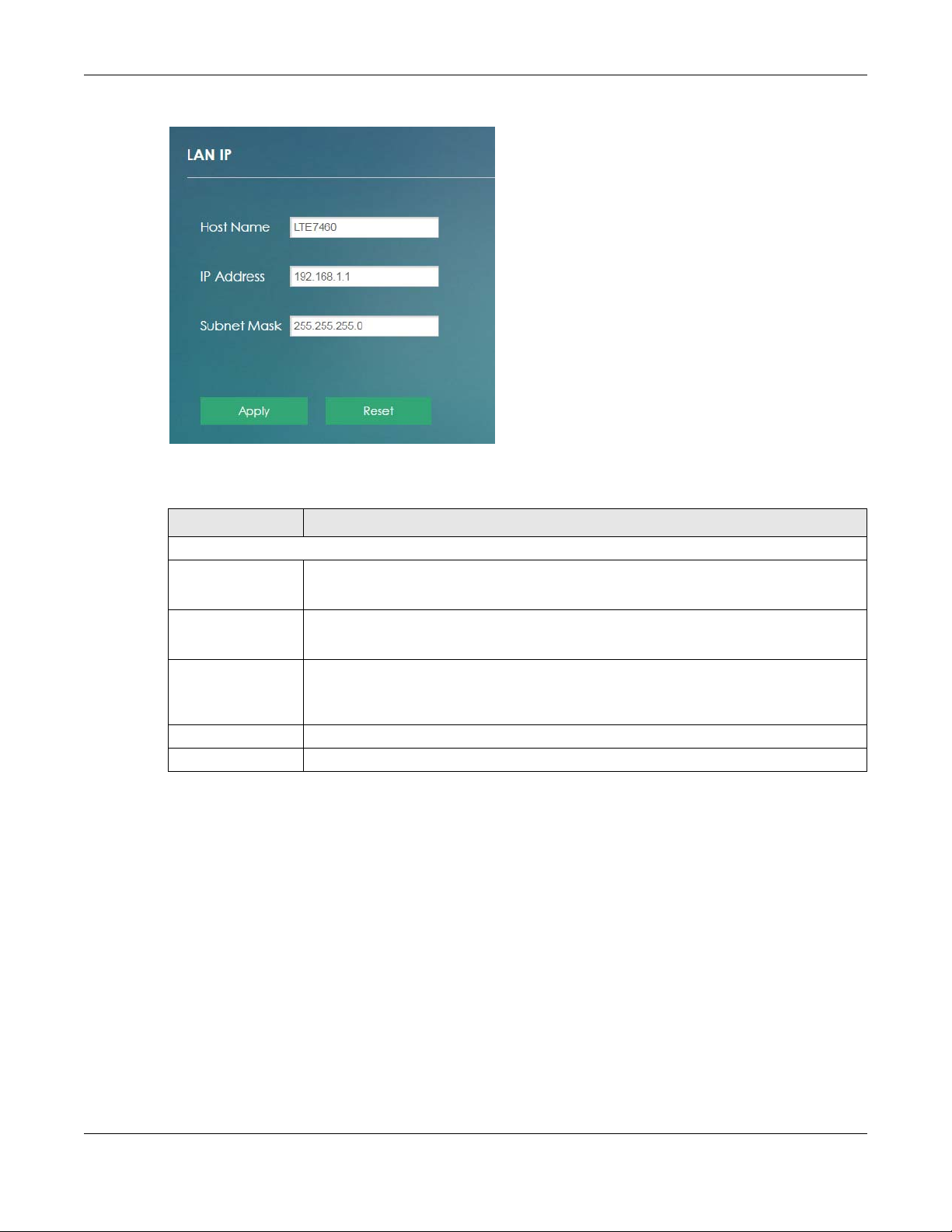
6.2 The LAN IP Screen
Click Home Networking to open the LAN IP screen. Use this screen to set the Local Area Network IP
address and subnet mask of your LTE7460-M608.
LTE7460-M608 User’s Guide
41
Page 42
Chapter 6 Home Network
Figure 23 Home Networking > LAN Setup
The following table describes the fields in this screen.
Table 12 Home Networking > LAN IP
LABEL DESCRIPTION
LAN IP
Host Name This shows the default host name.
Enter a new host name for the LTE7460-M608 if you want to change it.
IP Address This shows the default LAN IP address.
Enter the new IP address for the LTE7460-M608’s LAN interface if you want to change it.
Subnet Mask This shows the default subnet mask.
Enter the subnet mask of this interface in dot decimal notation. The subnet mask indicates
what part of the IP address is the same for all computers in the network.
Apply Click Apply to save your changes back to the LTE7460-M608.
Cancel Click Cancel to reload the previous configuration for this screen.
6.3 The DHCP Screen
The LTE7460-M608 has built-in DHCP server capability that assigns IP addresses to systems that support
DHCP client capability. Use this screen to enable the DHCP server. To access this screen, click Home
Network > DHCP.
LTE7460-M608 User’s Guide
42
Page 43

Figure 24 Home Network > DHCP
Chapter 6 Home Network
The following table describes the labels in the screen.
Table 13 Home Network > DHCP
LABEL DESCRIPTION
DHCP Settings
Enable DHCP Server Select the check box to enable the DHCP server on the LTE7460-M608.
Start IP The LTE7460-M608 is pre-configured with a pool of 241 IP addresses starting from
End IP This field specifies the last of the continuos addresses in the IP address pool.
Lease Time Specify how long (in minutes) each computer can use the information (especially
Static DHCP List
Add New Click Add New to create a new entry.
IP Address This field displays the IP address that the LTE7460-M608 assigns to a device with the
MAC address This field displays the MAC address of the device to which the LTE7460-M608 assigns
Action Click Edit to go to the screen where you can edit the static IP address.
Apply Click Apply to save your changes back to the LTE7460-M608.
Reset Click Reset to reload the previous configuration for this screen.
192.168.1.10 to 192.168.1.250.
This field specifies the first of the continuos addresses in the IP address pool.
the IP address).
This field displays the index number of the IP address entry.
entry’s MAC address.
the entry’s IP address.
Click Delete to remove the static IP address entry.
LTE7460-M608 User’s Guide
43
Page 44

Chapter 6 Home Network
6.4 The Static Route Screen
Use this screen to view and configure IP static routes on the LTE7460-M608. Click Home Network > Static
Route to open the following screen.
Figure 25 Home Network > Static Route
The following table describes the labels in this screen.
Table 14 Home Network > Static Route
LABEL DESCRIPTION
Static Route
Enable Static Route Select the check box to enable the static route on the LTE7460-M608.
Apply Click Apply to save your changes back to the LTE7460-M608.
Reset Click Reset to reload the previous configuration for this screen.
Static Route List
Add New Click Add New to set up a new static route on the LTE7460-M608.
# This field displays the index number of an individual static route.
Destination IP This field specifies the IP network address of the final destination. Routing is always
based on network number.
Subnet Mask This parameter specifies the IP network subnet mask of the final destination.
Interface This is the WAN interface through which the traffic is routed.
Gateway This is the IP address of the gateway. The gateway is a router or switch on the same
network segment as the device's LAN or WAN port. The gateway helps forward
packets to their destinations.
Metric This is the “cost” of transmission for routing purposes.
Action Click Edit to go to the screen where you can set up a static route on the LTE7460-
M608.
Click Delete to remove a static route from the LTE7460-M608.
Reset Click Reset to reload the previous configuration for this screen.
LTE7460-M608 User’s Guide
44
Page 45
6.5 The UPnP Screen
Universal Plug and Play (UPnP) is a distributed, open networking standard that uses TCP/IP for simple
peer-to-peer network connectivity between devices. A UPnP device can dynamically join a network,
obtain an IP address, convey its capabilities and learn about other devices on the network. In turn, a
device can leave a network smoothly and automatically when it is no longer in use. See page 48 for
more information on UPnP.
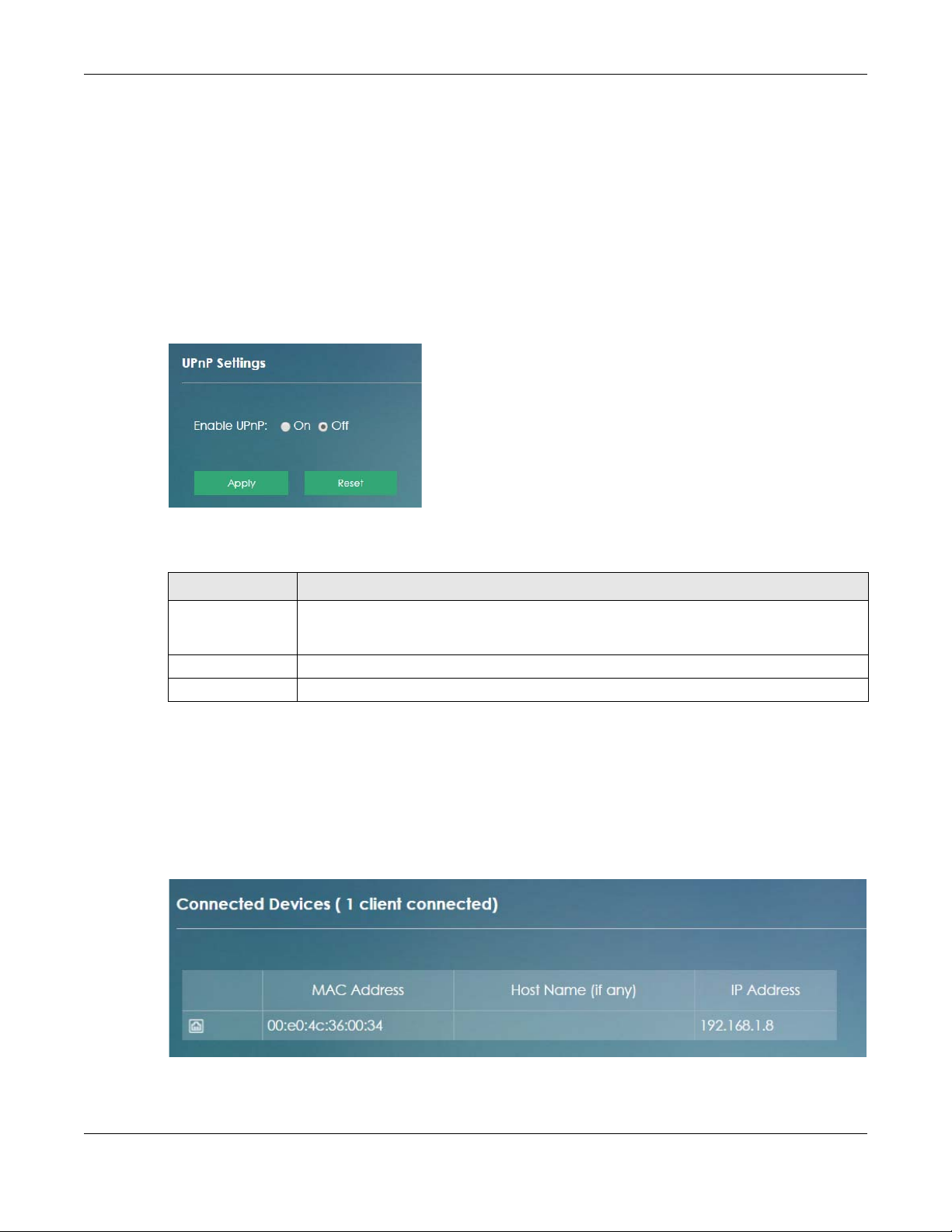
Use the following screen to configure the UPnP settings on your LTE7460-M608. Click Home Network >
UPnP to display the screen shown next.
Figure 26 Home Network > UPnP
Chapter 6 Home Network
The following table describes the labels in this screen.
Table 15 Network Settings > Home Networking > UPnP
LABEL DESCRIPTION
Enable UPnP Select On to activate UPnP. Be aware that anyone could use a UPnP application to open the
Apply Click Apply to save your changes.
Reset Click Reset to restore your previously saved settings.
web configurator's login screen without entering the LTE7460-M608's IP address (although you
must still enter the password to access the web configurator).
6.6 The Connected Devices Screen
Click Home Network > Connected Devices to view current information (including IP Address, Host Name
and MAC Address) of network clients connected to the LTE7460-M608. The following screen displays.
Figure 27 Home Network > Connected Devices
LTE7460-M608 User’s Guide
45
Page 46

Chapter 6 Home Network
The following table describes the labels in this screen.
Table 16 Home Network > Connected Devices
LABEL DESCRIPTION
This shows an icon representing how the device is connected to the LTE7460-M608.
MAC Address This field displays the MAC address of the device.
Host Name (if any) This displays the device host name.
IP Address This field displays the IP address that the LTE7460-M608 assigns to the device.
6.7 Technical Reference
This section provides some technical background information about the topics covered in this chapter.
LANs, WANs and the LTE7460-M608
The actual physical connection determines whether the LTE7460-M608 ports are LAN or WAN ports.
There are two separate IP networks, one inside the LAN network and the other outside the WAN network
as shown next.
Figure 28 LAN and WAN IP Addresses
DHCP Setup
DHCP (Dynamic Host Configuration Protocol, RFC 2131 and RFC 2132) allows individual clients to obtain
TCP/IP configuration at start-up from a server. You can configure the LTE7460-M608 as a DHCP server or
disable it. When configured as a server, the LTE7460-M608 provides the TCP/IP configuration for the
clients. If you turn DHCP service off, you must have another DHCP server on your LAN, or else the
computer must be manually configured.
LTE7460-M608 User’s Guide
46
Page 47

Chapter 6 Home Network
IP Pool Setup
The LTE7460-M608 is pre-configured with a pool of IP addresses for the DHCP clients (DHCP Pool). See the
product specifications in the appendices. Do not assign static IP addresses from the DHCP pool to your
LAN computers.
LAN TCP/IP
The LTE7460-M608 has built-in DHCP server capability that assigns IP addresses and DNS servers to
systems that support DHCP client capability.
IP Address and Subnet Mask
Similar to the way houses on a street share a common street name, so too do computers on a LAN share
one common network number.
Where you obtain your network number depends on your particular situation. If the ISP or your network
administrator assigns you a block of registered IP addresses, follow their instructions in selecting the IP
addresses and the subnet mask.
If the ISP did not explicitly give you an IP network number, then most likely you have a single user
account and the ISP will assign you a dynamic IP address when the connection is established. If this is
the case, it is recommended that you select a network number from 192.168.0.0 to 192.168.255.0 and
you must enable the Network Address Translation (NAT) feature of the LTE7460-M608. The Internet
Assigned Number Authority (IANA) reserved this block of addresses specifically for private use; please do
not use any other number unless you are told otherwise. Let's say you select 192.168.1.0 as the network
number; which covers 254 individual addresses, from 192.168.1.1 to 192.168.1.254 (zero and 255 are
reserved). In other words, the first three numbers specify the network number while the last number
identifies an individual computer on that network.
Once you have decided on the network number, pick an IP address that is easy to remember, for
instance, 192.168.1.1, for your LTE7460-M608, but make sure that no other device on your network is using
that IP address.
The subnet mask specifies the network number portion of an IP address. Your LTE7460-M608 will compute
the subnet mask automatically based on the IP address that you entered. You don't need to change
the subnet mask computed by the LTE7460-M608 unless you are instructed to do otherwise.
Private IP Addresses
Every machine on the Internet must have a unique address. If your networks are isolated from the
Internet, for example, only between your two branch offices, you can assign any IP addresses to the
hosts without problems. However, the Internet Assigned Numbers Authority (IANA) has reserved the
following three blocks of IP addresses specifically for private networks:
• 10.0.0.0 — 10.255.255.255
• 172.16.0.0 — 172.31.255.255
• 192.168.0.0 — 192.168.255.255
You can obtain your IP address from the IANA, from an ISP or it can be assigned from a private network.
If you belong to a small organization and your Internet access is through an ISP, the ISP can provide you
LTE7460-M608 User’s Guide
47
Page 48

Chapter 6 Home Network
with the Internet addresses for your local networks. On the other hand, if you are part of a much larger
organization, you should consult your network administrator for the appropriate IP addresses.
Note: Regardless of your particular situation, do not create an arbitrary IP address; always
follow the guidelines above. For more information on address assignment, please refer
to RFC 1597, “Address Allocation for Private Internets” and RFC 1466, “Guidelines for
Management of IP Address Space”.
6.8 Installing UPnP in Windows Example
This section shows how to install UPnP in Windows Me and Windows XP.
Installing UPnP in Windows Me
Follow the steps below to install the UPnP in Windows Me.
1 Click Start and Control Panel. Double-click Add/Remove Programs.
2 Click the Windows Setup tab and select Communication in the Components selection box. Click Details.
Figure 29 Add/Remove Programs: Windows Setup: Communication
3 In the Communications window, select the Universal Plug and Play check box in the Components
selection box.
LTE7460-M608 User’s Guide
48
Page 49

Chapter 6 Home Network
Figure 30 Add/Remove Programs: Windows Setup: Communication: Components
4 Click OK to go back to the Add/Remove Programs Properties window and click Next.
5 Restart the computer when prompted.
Installing UPnP in Windows XP
Follow the steps below to install the UPnP in Windows XP.
1 Click Start and Control Panel.
2 Double-click Network Connections.
3 In the Network Connections window, click Advanced in the main menu and select Optional Networking
Components ….
Figure 31 Network Connections
4 The Windows Optional Networking Components Wizard window displays. Select Networking Service in
the Components selection box and click Details.
LTE7460-M608 User’s Guide
49
Page 50

Chapter 6 Home Network
Figure 32 Windows Optional Networking Components Wizard
5 In the Networking Services window, select the Universal Plug and Play check box.
Figure 33 Networking Services
6 Click OK to go back to the Windows Optional Networking Component Wizard window and click Next.
6.9 Using UPnP in Windows XP Example
This section shows you how to use the UPnP feature in Windows XP. You must already have UPnP
installed in Windows XP and UPnP activated on the LTE7460-M608.
Make sure the computer is connected to a LAN port of the LTE7460-M608. Turn on your computer
and the LTE7460-M608.
LTE7460-M608 User’s Guide
50
Page 51

Chapter 6 Home Network
Auto-discover Your UPnP-enabled Network Device
1 Click Start and Control Panel. Double-click Network Connections. An icon displays under
Internet Gateway.
2 Right-click the icon and select Properties.
Figure 34 Network Connections
3 In the Internet Connection Properties window, click Settings to see the port mappings there
were automatically created.
Figure 35 Internet Connection Properties
4 You may edit or delete the port mappings or click Add to manually add port mappings.
LTE7460-M608 User’s Guide
51
Page 52

Chapter 6 Home Network
Figure 36 Internet Connection Properties: Advanced Settings
Figure 37 Internet Connection Properties: Advanced Settings: Add
5 When the UPnP-enabled device is disconnected from your computer, all port mappings will be deleted
automatically.
6 Select Show icon in notification area when connected option and click OK. An icon displays in the
system tray.
Figure 38 System Tray Icon
7 Double-click on the icon to display your current Internet connection status.
LTE7460-M608 User’s Guide
52
Page 53

Chapter 6 Home Network
Figure 39 Internet Connection Status
Web Configurator Easy Access
With UPnP, you can access the web-based configurator on the LTE7460-M608 without finding out the IP
address of the LTE7460-M608 first. This comes helpful if you do not know the IP address of the LTE7460M608.
Follow the steps below to access the web configurator.
1 Click Start and then Control Panel.
2 Double-click Network Connections.
3 Select My Network Places under Other Places.
LTE7460-M608 User’s Guide
53
Page 54

Figure 40 Network Connections
Chapter 6 Home Network
4 An icon with the description for each UPnP-enabled device displays under Local Network.
5 Right-click on the icon for your LTE7460-M608 and select Invoke. The web configurator login screen
displays.
Figure 41 Network Connections: My Network Places
6 Right-click on the icon for your LTE7460-M608 and select Properties. A properties window displays with
basic information about the LTE7460-M608.
LTE7460-M608 User’s Guide
54
Page 55

Chapter 6 Home Network
Figure 42 Network Connections: My Network Places: Properties: Example
6.10 Using UPnP in Windows 7 Example
This section shows you how to use the UPnP feature in Windows 7. You must already have UPnP installed
in Windows XP and UPnP activated on the LTE7460-M608.
Make sure the computer is connected to a LAN port of the LTE7460-M608. Turn on your computer and
the LTE7460-M608.
Auto-discover Your UPnP-enabled Network Device
1 Click Start and Control Panel. Then click the Network and Sharing Center.
2 In the left pane, select Change advanced sharing settings to display the Home or Work section.
3 In the Network Discovery section, select the option for Turn on network discovery and click the Save
changes button.
LTE7460-M608 User’s Guide
55
Page 56

Chapter 6 Home Network
Figure 43 Change advanced sharing settings
LTE7460-M608 User’s Guide
56
Page 57

7.1 Overview
This chapter describes how you can configure the LTE7460-M608’s operating mode, IP/port filtering,
ALG, DoS Attack, DNS and DDNS settings.
7.1.1 What You Can Do in this Chapter
• Use the Operating Mode screen to configure the LTE7460-M608’s operating mode (Section 7.2 on
page 59).
• Use the TR069 to configure the LTE7460-M608’s TR-069 auto-configuration settings.(Section 7.3 on page
61).
• Use the DNS Settings screen to configure the LTE7460-M608’s DNS settings (Section 7.4 on page 63).
• Use the Firewall screen to protect your LTE7460-M608 from attacks on the Internet and control access
to it (Section 7.5 on page 64 to Section 7.10 on page 70).
• Use the DDNS Settings screen to enable and configure the LTE7460-M608’s DDNS (Section 7.11 on
page 71).
• Use the VPN Pass Through screen to allow VPN traffic to pass through the LTE7460-M608 (Section 7.12
on page 72).
• Use the Certificate Management screen to upload or view the current certificate used for HTTPs and
SSH (Section 7.13 on page 73).
• Use the Bandwidth Management screen to configure the LTE7460-M608 bandwidth profiles (Section
7.14 on page 74).
• Use the Remote Management screen to configure port settings for the WAN side access to the
LTE7460-M608 (Section 7.15 on page 76).
• Use the ICMP screen to change the LTE7460-M608’s security settings. (Section 7.16 on page 78).
CHAPTER 7
Networking
Note: DNS Settings, Firewall, DDNS, VPN Pass Through, Bandwidth Management and ICMP
screens are not available if your LTE7460-M608’s operating mode is on bridge mode. To
learn more about changing your LTE7460-M608’s operating mode see Section 7.2 on
page 59.
7.1.2 What you need to know
The following terms and concepts may help as you read this chapter.
DNS
DNS (Domain Name System) maps a domain name to its corresponding IP address and vice versa. The
DNS server is extremely important because without it, you must know the IP address of a computer
before you can access it. The DNS server addresses you enter when you set up DHCP are passed to the
client machines along with the assigned IP address and subnet mask.
LTE7460-M608 User’s Guide
57
Page 58

Chapter 7 Networking
File Transfer Protocol
This is a method of transferring data from one computer to another over a network such as the Internet.
DYNDNS Wildcard
Enabling the wildcard feature for your host causes *.yourhost.dyndns.org to be aliased to the same IP
address as yourhost.dyndns.org. This feature is useful if you want to be able to use, for example,
www.yourhost.dyndns.org and still reach your hostname.
If you have a private WAN IP address, then you cannot use Dynamic DNS.
Firewall
A firewall protects your LTE7460-M608 and network from attacks by hackers on the Internet and control
access to it. The firewall:
• allows traffic that originates from your LAN computers to go to all other networks.
• blocks traffic that originates on other networks from going to the LAN.
• blocks SYN and port scanner attacks.
By default, the LTE7460-M608 blocks DDOS, LAND and Ping of Death attacks whether the firewall is
enabled or disabled.
The following figure illustrates the firewall action. User A can initiate an IM (Instant Messaging) session
from the LAN to the WAN (1). Return traffic for this session is also allowed (2). However other traffic
initiated from the WAN is blocked (3 and 4).
Figure 44 Default Firewall Action
Inside/Outside and Global/Local
Inside/outside denotes where a host is located relative to the LTE7460-M608, for example, the computers
of your subscribers are the inside hosts, while the web servers on the Internet are the outside hosts.
Global/local denotes the IP address of a host in a packet as the packet traverses a router, for example,
the local address refers to the IP address of a host when the packet is in the local network, while the
global address refers to the IP address of the host when the same packet is traveling in the WAN side.
LTE7460-M608 User’s Guide
58
Page 59

Chapter 7 Networking
NAT
In the simplest form, NAT changes the source IP address in a packet received from a subscriber (the
inside local address) to another (the inside global address) before forwarding the packet to the WAN
side. When the response comes back, NAT translates the destination address (the inside global address)
back to the inside local address before forwarding it to the original inside host. See Section 7.17 on page
78 for advanced technical information on NAT.
Certification Authorities
A Certification Authority (CA) issues certificates and guarantees the identity of each certificate owner.
There are commercial certification authorities like CyberTrust or VeriSign and government certification
authorities.
Certification Path
A certification path is the hierarchy of certification authority certificates that validate a certificate. The
LTE7460-M608 does not trust a certificate if any certificate on its path has expired or been revoked.
Certificate Directory Servers
Certification authorities maintain directory servers with databases of valid and revoked certificates. A
directory of certificates that have been revoked before the scheduled expiration is called a CRL
(Certificate Revocation List). The LTE7460-M608 can check a peer’s certificate against a directory
server’s list of revoked certificates. The framework of servers, software, procedures and policies that
handles keys is called PKI (public-key infrastructure).
Advantages of Certificates
Certificates offer the following benefits.
• The LTE7460-M608 only has to store the certificates of the certification authorities that you decide to
trust, no matter how many devices you need to authenticate.
• Key distribution is simple and very secure since you can freely distribute public keys and you never
need to transmit private keys.
Certificate File Format
The certification authority certificate that you want to import has to be in PEM (Base-64) encoded X.509
file format. This Privacy Enhanced Mail format uses 64 ASCII characters to convert a binary X.509
certificate into a printable form.
7.2 Operating Mode Screen
The LTE7460-M608 offers two different operation modes: Router mode and Bridge mode. The LTE7460M608 is set to Router mode by default.
LTE7460-M608 User’s Guide
59
Page 60

7.2.1 Router mode
In Router mode your LTE7460-M608 connects your local network with another network, like the Internet.
Use Router mode if your Internet service provider gives you one IP address only and you want multiple
computers to share an Internet account.
Figure 45 LAN and WAN IP Addresses in Router Mode
7.2.2 Bridge mode
Chapter 7 Networking
Use Bridge mode on the LTE7460-M608 you want the connected devices to get individual IP addresses
from the Internet service provider’s DHCP. If you select Bridge mode, you cannot use routing functions,
such as VPN Pass Through, Firewall, DHCP server and NAT on traffic from the selected LAN port(s).
Click Networking > Operating Mode to open the following screen and change your LTE7460-M608’s
operating mode.
Figure 46 Networking > Operating Mode
The following table describes the labels in the screen.
Table 17 Networking > Operating Mode
LABEL DESCRIPTION
Operating Mode
Enable Router Mode Select this check box to change the LTE7460-M608’s operating mode to Router
Mode.
LTE7460-M608 User’s Guide
60
Page 61
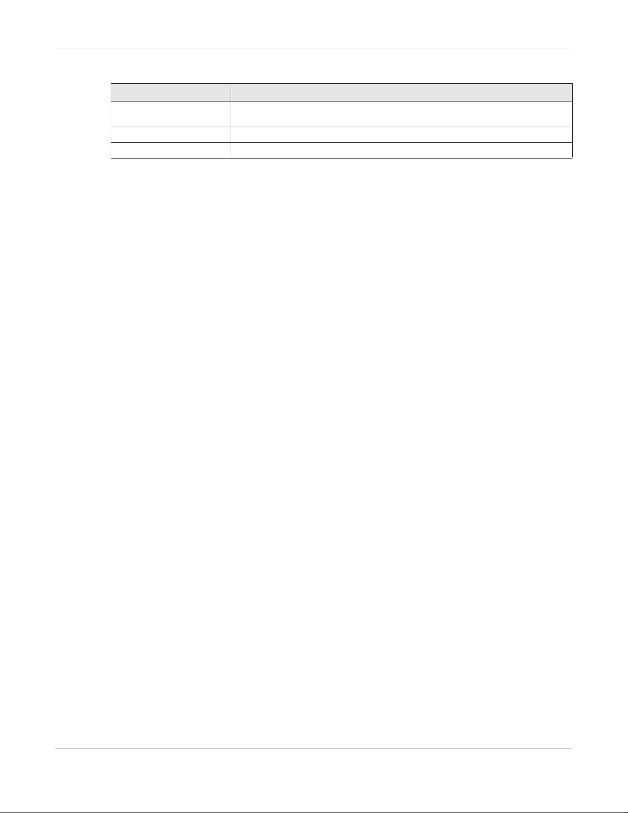
Table 17 Networking > Operating Mode
LABEL DESCRIPTION
Enable Bridge Mode Select this check box to change the LTE7460-M608’s operating mode to Bridge
Apply Click Apply to save your changes.
Reset Click Reset to restore your previously saved settings.
7.3 TR069 Screen
TR-069 defines how Customer Premise Equipment (CPE), for example your LTE7460-M608, can be
managed over the WAN by an Auto Configuration Server (ACS). TR-069 is based on sending Remote
Procedure Calls (RPCs) between an ACS and a client device. RPCs are sent in Extensible Markup
Language (XML) format over HTTP or HTTPS.
An administrator can use an ACS to remotely set up the LTE7460-M608, modify settings, perform firmware
upgrades as well as monitor and diagnose the LTE7460-M608. You have to enable the device to be
managed by the ACS and specify the ACS IP address or domain name and username and password.
Chapter 7 Networking
Mode.
Click Networking > TR069 to open the following screen. Use this screen to configure you LTE7460-M608 to
be managed by an ACS.
LTE7460-M608 User’s Guide
61
Page 62

Figure 47 Networking > TR069
Chapter 7 Networking
The following table describes the labels in this screen.
Table 18 Networking > TR069
LABEL DESCRIPTION
TR-069 Configuration
CWMP Click the check box to allow the LTE7460-M608 to be managed by a management
server. Otherwise, so the LTE7460-M608 is not managed by a management server.
ACS URL Enter the URL or IP address of the auto-configuration server.
ACS User Name
ACS Password Enter the TR-069 password for authentication with the auto-configuration server.
Enter the TR-069 user name for authentication with the auto-configuration server
LTE7460-M608 User’s Guide
62
.
Page 63

Chapter 7 Networking
The following table describes the labels in this screen.
Table 18 Networking > TR069
LABEL DESCRIPTION
Connection Request User
Name
Connection Request
Password
Connection Request Port The default port for access to the LTE7460-M608 from the management server is the
Inform Select Enable for the LTE7460-M608 to send periodic inform via TR-069 on the WAN.
Inform Interval Enter the time interval (in seconds) at which the LTE7460-M608 sends information to
Bound Interface Name Select whether the TR069 connection path is WAN1 or WAN2.
Apply Click Apply to save your changes.
Reset Click Reset to restore the screen’s last saved settings.
Import Certificate File
Select a File Use this field to upload a certificate the LTE7460-M608 uses for TLS/SSL
Apply Click Apply to upload the certificate.
Current TR-069 Certificate file
File Name This field displays the name used to identify this TR-069 certificate. It is recommended
Subject This field displays identifying information about the certificate’s owner, such as CN
Issuer This field displays identifying information about the certificate’s issuing certification
Valid From This field displays the date that the certificate becomes applicable. The text displays
Valid To This field displays the date that the certificate expires. The text displays in red and
Enter the connection request user name. When the ACS makes a connection
request to theLTE7460-M608, this user name is used to authenticate the ACS.
Enter the connection request password. When the ACS makes a connection request
to the LTE7460-M608, this password is used to authenticate the ACS.
HTTP port, port 80. If you change it, make sure it does not conflict with another port
on your network and it is recommended to use a port number above 1024 (not a
commonly used port). The management server should use this port to connect to
the LTE7460-M608. You may need to alter your NAT port forwarding rules if they were
already configured.
Otherwise, select Disable.
the autoconfiguration server.
authentication.
that you give each certificate a unique name.
(Common Name), OU (Organizational Unit or department), O (Organization or
company), S (State), and C (Country). It is recommended that each certificate has
unique subject information.
authority, such as a common name, organizational unit or department, organization
or company and country.
in red and includes a Not Valid! message if the certificate has not yet become
applicable.
includes an Expired! message if the certificate is about to expire or has already
expired.
7.4 DNS Settings Screen
Click Networking > DNS Settings to configure the DNS servers your LTE7460-M608 uses. The following
screen displays.
LTE7460-M608 User’s Guide
63
Page 64

Chapter 7 Networking
Figure 48 Networking > DNS Settings
The following table describes the labels in this screen
Table 19 Networking > DNS Settings
LABEL DESCRIPTION
DNS Settings
DNS Mode Select Auto if your LTE7460-M608 pass DHCP server to the LAN users. Otherwise,
select Manual if you to assign a specific DNS server information to the LAN users.
have the IP address of a DNS server.
Apply Click Apply to save your changes.
Reset Click Reset to restore the screen’s last saved settings.
7.5 Firewall > IPv4/Port Filter Screen
The LTE7460-M608 firewall is a packet filtering firewall and restricts access based on the source/
destination computer network address of a packet and the type of application. Use this screen to
configure IP filtering rules. IPv6/Port Filter is useful to allow or block any traffic to/from specific IPv6
addresses or TCP/UDP ports. To access this screen, click Networking > Firewall > IPv4/Port Filter.
Figure 49 Networking > Firewall > IPv4/Port Filter
LTE7460-M608 User’s Guide
64
Page 65

Chapter 7 Networking
The following table describes the labels in this screen
Table 20 Networking > Firewall > IPv4/Port Filter
LABEL DESCRIPTION
IPv4/Port Filter
Enable IPv4/Port Filter Select the check box to enable the rule.
IPv4/Port Filtering Policy Select Whitelist to allow packets that match the filtering rules defined on this screen
IPv4/Port Filter List
Add new Click Add New to create a new rule.
Source IP This field displays the source IPv4 addresses to which this rule applies.
Port This field displays a single port number of the source or a port range.
Protocol This field displays the protocol (TCP, UDP, TCP+UDP or any) used to transport the
Dest. IP This field displays the destination IPv4 addresses to which this rule applies.
Port This field displays a single port number of the destination or a port range.
to pass through. Select Blacklist to block packets that match the filtering rules
defined on this screen.
This field displays the rule index number.
Enter the port number/range of the source that define the traffic type, for example
TCP port 80 defines web traffic. Use a dash (-) to enter port ranges, for example TCP
ports 80-82.
packets for which you want to apply the rule. Select Any and all traffic from a
Source IP and Destination IP is filtered.
Enter the port number/range of the destination that define the traffic type, for
example TCP port 80 defines web traffic.Use a dash (-) to enter port ranges, for
example TCP ports 80-82.
Comment Enter descriptions of the rule in this field.
Action Click Edit to go to the screen where you can edit the filtering rule.
Click Delete to remove the filtering rule.
Apply Click Apply to save your changes.
Reset Click Reset to restore the screen’s last saved settings.
7.6 Firewall > IPv6/Port Filter Screen
Use this screen to configure IP filtering rules. IPv6/Port Filter is useful to allow or block any traffic to/from
specific IPv6 addresses or TCP/UDP ports. To access this screen, click Networking > Firewall > IPv6/Port
Filter.
LTE7460-M608 User’s Guide
65
Page 66

Chapter 7 Networking
Figure 50 Networking > Firewall > IPv6/Port Filter
The following table describes the labels in this screen.
Table 21 Networking > Firewall > IPv6/Port Filter
LABEL DESCRIPTION
IPv6/Port Filter
Enable IPv6/Port
Filter
IPv6/Port
Filtering Policy
IPv6/Port Filter List
Add New Click Add New to create a new rule.
Source IP This field displays the source IPv6 addresses to which this rule applies.
Port This field displays a single port number of the source or a port range.
Protocol This field displays the protocol (TCP, UDP, TCP+UDP or any) used to transport the packets for
Dest. IP This field displays the destination IPv6 addresses to which this rule applies.
Port This field displays a single port number of the destination or a port range.
Comment Enter descriptions of the rule in this field.
Action Click Edit to go to the screen where you can edit the filtering rule.
Apply Click Apply to save your changes back to the LTE7460-M608.
Reset Click Reset to reload the previous configuration for this screen.
Select the check box to enable the rule.
Select Whitelist to allow packets that match the filtering rules defined on this screen to pass
through. Select Blacklist to block packets that match the filtering rules defined on this screen.
This field displays the rule index number.
Enter the port number/range of the source that define the traffic type, for example TCP port 80
defines web traffic.
which you want to apply the rule. Select Any and all traffic from a Source IP and Destination IP is
filtered.
Enter the port number/range of the destination that define the traffic type, for example TCP port
80 defines web traffic.
Click Delete to remove the filtering rule.
LTE7460-M608 User’s Guide
66
Page 67

Chapter 7 Networking
7.7 Firewall > IP/Port Forwarding Screen
Use this screen to configure port forwarding rules. Servers outside the LTE7460-M608’s LAN can access
devices inside your LAN through IP/Port forwarding.
The following figure shows how port forwarding works. Server A in the Internet wants to access the
computer B inside your LTE7460-M608’s network. A can find the LTE7460-M608 through its public IP
address but it cannot access B. When you enable port forwarding A can use a Global Port to get into
your LAN, the LTE7460-M608 forwards this request to a Private Port inside your LAN to B’s IP address.
Figure 51 How Port Forwarding Works
To access this screen, click Networking > Firewall > IP/Port Forwarding.
Figure 52 Networking > Firewall > IP/Port Forwarding
The following table describes the labels in this screen.
Networking > Firewall > IP/Port Forwarding
LABEL DESCRIPTION
IP/Port Forwarding
Enable IP/Port
Forwarding
Select the check box to enable port forwarding rules.
LTE7460-M608 User’s Guide
67
Page 68

Chapter 7 Networking
Networking > Firewall > IP/Port Forwarding
LABEL DESCRIPTION
Filter List
Add New Click Add New to create a new rule.
This field displays the rule index number.
Private IP This field displays the inside IP address of the server.
Enter the inside IP address of the virtual server here.
Private Port A private port is a port that causes (or triggers) the LTE7460-M608 to record the IP address of the
Global Port A global port is a port that a server on the WAN uses when it sends out a particular service. The
Protocol This field displays the protocol (TCP, UDP, TCP+UDP) used to transport the packets for which you
Action Click Edit to go to the screen where you can edit the port forwarding rule.
Apply Click Apply to save your changes back to the LTE7460-M608.
Reset Click Reset to reload the previous configuration for this screen.
LAN computer that sent the traffic to a server on the WAN.
Enter the port number/range of the private in this field.
LTE7460-M608 forwards the traffic with this port to the client computer on the LAN that requested
the service.
Enter the port number/range of the global in this field.
want to apply the rule.
Click Delete to remove the port forwarding rule.
7.8 Firewall > DoS Attack Screen
Use this screen to enable DoS protection. DoS protection is used to prevent denial of service attacks and
control the number of sessions between interfaces or addresses. Click Networking > Firewall > DoS
Attack to display the following screen.
Figure 53 Networking > Firewall > DoS Attack
LTE7460-M608 User’s Guide
68
Page 69

Chapter 7 Networking
The following table describes the labels in this screen.
Table 22 Networking > Firewall > DoS Attack
LABEL DESCRIPTION
DoS Attack
Enable DoS Protection Enable this to protect against DoS attacks. The LTE7460-M608 will drop sessions that
SYN Flood This is the rate of new TCP half-open sessions per second that causes the firewall to
Echo Storm This is the rate of new Echo Request half-open sessions per second that causes the
ICMP Flood This is the rate of new ICMP Request (other than Echo) half-open sessions per second
Apply Click Apply to save your changes back to the LTE7460-M608.
Reset Click Reset to reload the previous configuration for this screen.
surpass maximum thresholds.
start deleting half-open sessions. When the rate of new connection attempts rises
above this number, the LTE7460-M608 deletes half-open sessions as required to
accommodate new connection attempts.
firewall to start deleting half-open sessions. When the rate of new connection
attempts rises above this number, the LTE7460-M608 deletes half-open sessions as
required to accommodate new connection attempts.
that causes the firewall to start deleting half-open sessions. When the rate of new
connection attempts rises above this number, the LTE7460-M608 deletes half-open
sessions as required to accommodate new connection attempts.
7.9 Firewall > ALG Screen
Click Networking > Firewall > ALG to open the ALG (Application Layer Gateway) screen. Use this screen
to add NAT (Network Address Translation) filters into your LTE7460-M608’s gateway to support packets
and sessions for certain application layer protocols.
Figure 54 Networking > Firewall > ALG
LTE7460-M608 User’s Guide
69
Page 70

Chapter 7 Networking
The following table describes the labels in this screen.
Table 23 Networking > Firewall > ALG
LABEL DESCRIPTION
Application Layer Gateway (ALG) Settings
FTP ALG Select Enable for File Transfer Protocol (FTP) ALG to detect FTP traffic and help build
TFTP ALG Select Enable for Trivial File Transfer Protocol (TFTP) ALG to detect TFTP packets and
PPTP ALG Select Enable for Point-to-Point Tunneling Protocol (PPTP) ALG to detect PPTP and
RTSP ALG Select Enable for Real Time Streaming Protocol (RTSP) ALG to detect RTSP traffic and
SIP ALG Select Enable for Session Initiation Protocol (SIP) ALG to detect SIP traffic and help
Apply Click Apply to save your changes back to the LTE7460-M608.
Reset Click Reset to reload the previous configuration for this screen.
FTP sessions through the LTE7460-M608, otherwise select Disable.
help build TFTP sessions through the LTE7460-M608, otherwise select Disable.
help build PPTP sessions through the LTE7460-M608, otherwise select Disable.
help build RTSP sessions through the LTE7460-M608, otherwise select Disable.
build SIP sessions through the LTE7460-M608, otherwise select Disable.
7.10 Firewall > DMZ Screen
Click Networking > Firewall > DMZ to open the DMZ screen. Use this screen to specify the IP address of a
default server to receive packets from ports.
Figure 55 Networking > Firewall > DMZ
The following table describes the labels in this screen.
Table 24 Networking > Firewall > DMZ
LABEL DESCRIPTION
Enable DMZ Click on the check box to enable the DMZ in your LTE7460-M608.
IP Address Enter the IP address of the default server which receives packets from ports.
Apply Click Apply to save your changes back to the LTE7460-M608.
Reset Click Reset to reload the previous configuration for this screen.
LTE7460-M608 User’s Guide
70
Page 71

Chapter 7 Networking
7.11 DDNS Settings Screen
Dynamic DNS allows you to update your current dynamic IP address with one or many dynamic DNS
services so that anyone can contact you (in applications such as NetMeeting and CU-SeeMe). You can
also access your FTP server or Web site on your own computer using a domain name (for instance
myhost.dhs.org, where myhost is a name of your choice) that will never change instead of using an IP
address that changes each time you reconnect. Your friends or relatives will always be able to call you
even if they don't know your IP address.
First of all, you need to have registered a dynamic DNS account with www.dyndns.org. This is for people
with a dynamic IP from their ISP or DHCP server that would still like to have a domain name. The Dynamic
DNS service provider will give you a password or key.
Use the Dynamic DNS screen to enable DDNS and configure the DDNS settings on the LTE7460-M608. To
change your LTE7460-M608’s DDNS, click Networking > DDNS Settings. The screen appears as shown.
Figure 56 Networking > DDNS Settings
The following table describes the labels in this screen.
Table 25 Networking > DDNS Settings
LABEL DESCRIPTION
Dynamic DNS Settings
Enable Dynamic DNS Select the check box to use Dynamic DNS.
Server Select the name of your Dynamic DNS service provider.
Domain Name Type the domain name assigned to your LTE7460-M608 by your Dynamic DNS service
User Name Type your user name for the Dynamic DNS service provider.
Password Type your password for the Dynamic DNS service provider.
Apply Click Apply to save your changes back to the LTE7460-M608.
Reset Click Reset to reload the previous configuration for this screen.
provider.
LTE7460-M608 User’s Guide
71
Page 72

Chapter 7 Networking
7.12 VPN Pass Through Screen
Click Networking > VPN Pass Through to open the following screen. Use this screen to enable different
types of VPN pass through so that VPN traffic can be sent through the LTE7460-M608.
Figure 57 Networking > VPN Pass Through
The following table describes the labels in this screen.
Table 26 Networking > VPN Pass Through
LABEL DESCRIPTION
VPN Pass Through
PPTP Pass Through Select Enable to allow VPN clients to make outbound PPTP connections. It is required
in order to connect to a PPTP VPN account. If PPTP is disabled, then when a client
sends a request to a VPN server, the server will reply to the LTE7460-M608 and the
LTE7460-M608 will drop the request. When PPTP is enabled, the LTE7460-M608 will
forward the reply from the VPN server to the client that initiated the request, and the
connection will establish successfully.
IPSec Pass Through Select Enable to allow VPN clients to make outbound IPSec connections. It is
required in order to connect to a IPSec VPN account. If IPSEC is disabled, then when
a client sends a request to a VPN server, the server will reply to the LTE7460-M608 and
the LTE7460-M608 will drop the request. When IPSEC is enabled, the LTE7460-M608 will
forward the reply from the VPN server to the client that initiated the request, and the
connection will establish successfully.
L2TP Pass Through Select Enable to allow VPN clients to make outbound L2TP connections. It is required
Apply Click Apply to save your changes back to the LTE7460-M608.
Reset Click Reset to reload the previous configuration for this screen.
in order to connect to a L2TP VPN account. If L2TP is disabled, then when a client
sends a request to a VPN server, the server will reply to the LTE7460-M608 and the
LTE7460-M608 will drop the request. When L2TP is enabled, the LTE7460-M608 will
forward the reply from the VPN server to the client that initiated the request, and the
connection will establish successfully.
LTE7460-M608 User’s Guide
72
Page 73

Chapter 7 Networking
7.13 Certificate Management Screen
The LTE7460-M608 can use certificates (also called digital IDs) to authenticate users. Certificates are
based on public-private key pairs. A certificate contains the certificate owner’s identity and public key.
Certificates provide a way to exchange public keys for use in authentication.
Use this screen to view the LTE7460-M608’s summary list of certificates and certification requests and
import certificates to authenticate the users in the LTE7460-M608’s network. You can import the following
certificates to your LTE7460-M608:
• Web Server - This certificate secures HTTP connections.
• SSH- This certificate secures remote connections.
Click on Networking > Certificate Management to open this screen.
Figure 58 Networking > Certificate Management
LTE7460-M608 User’s Guide
73
Page 74

Chapter 7 Networking
The following table describes the labels in this screen.
Table 27 Networking > Certificate Management
LABEL DESCRIPTION
Import Certificate File
Web Certificate Click Choose File to find the web server certificate file you want to upload. Then
SSH Certificate Click Choose File to find the SSH certificate file you want to upload. Then click Apply
Current WebServer Certificate File
File Name This field displays the name used to identify this web server certificate. It is
Subject This field displays identifying information about the certificate’s owner, such as CN
Issuer This field displays identifying information about the certificate’s issuing certification
Valid from This field displays the date that the certificate becomes applicable. The text displays
Valid to This field displays the date that the certificate expires. The text displays in red and
Cert Click Download Certificate File to download the web server certificate file.
Current SSH Certificate file
File Name This field displays the name used to identify this SSH certificate. It is recommended
Key Type This field applies to the SSH/SCP/SFTP certificate.
click Apply to upload it to your LTE7460-M608.
to upload it to your LTE7460-M608.
recommended that you give each certificate a unique name.
(Common Name), OU (Organizational Unit or department), O (Organization or
company), S (State), and C (Country). It is recommended that each certificate has
unique subject information.
authority, such as a common name, organizational unit or department, organization
or company and country.
in red and includes a Not Valid message if the certificate has not yet become
applicable.
includes an Expired! message if the certificate is about to expire or has already
expired.
that you give each certificate a unique name.
This shows the file format of the current certificate
7.14 Bandwidth Management Screen
Use this screen to map a connected device’s MAC address to one of four different priority profiles (Best
effor, High, Medium and Normal). The priority will
Unconfigured MAC addresses use the default profile. Click on Networking > Bandwidth Management to
display the following screen.
LTE7460-M608 User’s Guide
.
74
Page 75

Chapter 7 Networking
Figure 59 Networking > Bandwidth Management
The following table describes the labels in this screen.
Table 28 Networking > Bandwidth Management
LABEL DESCRIPTION
Bandwidth Management
Enable Bandwidth
Management
Profile of Bandwidth Management
Best effort Best Effort is the bandwidth management profile with the highest priority. Enter the
High Enter the data rate for both Uplink (UL) and Downlink (DL) in MB/s for the High
Medium Enter the data rate for both Uplink (UL) and Downlink (DL) in MB/s for the Medium
Normal Enter the data rate for both Uplink (UL) and Downlink (DL) in MB/s for the Normal
Default Select a profile from the drop-down list to be the LTE7460-M608’s default bandwidth
Bandwidth Management List
Add new Click Add new to add a new device to one of the LTE7460-M608’s bandwidth
# This field displays the device’s index number.
Select the check box to use the Bandwidth Management.
data rate for both Uplink (UL) and Downlink (DL) in MB/s for the Best Effort profile.
bandwidth management profile.
bandwidth management profile.
bandwidth management profile.
management profile.
management profiles.
LTE7460-M608 User’s Guide
75
Page 76

Chapter 7 Networking
Table 28 Networking > Bandwidth Management
LABEL DESCRIPTION
MAC Address This field displays the device’s MAC address.
Profile This field displays the type of bandwidth profile for the device.
Action Click Edit to go to the screen where you can edit the MAC address and/or the
bandwidth management profile.
Click Delete to remove the device from the list.
Apply Click Apply to save your changes back to the LTE7460-M608.
Reset Click Reset to reload the previous configuration for this screen.
7.15 Remote Management Screen
Remote management allows you to determine which services/protocols can access which LTE7460M608 interface (if any) and from which computers. The following figure shows remote management of
the LTE7460-M608 coming in from the WAN.
Figure 60 Remote Management from the WAN
Note: Remote management does not work if the Secured Client IP Address field does not
match the client IP address, or if there is a firewall rule that blocks it.
Click Networking > Remote Management to open the following screen.
LTE7460-M608 User’s Guide
76
Page 77
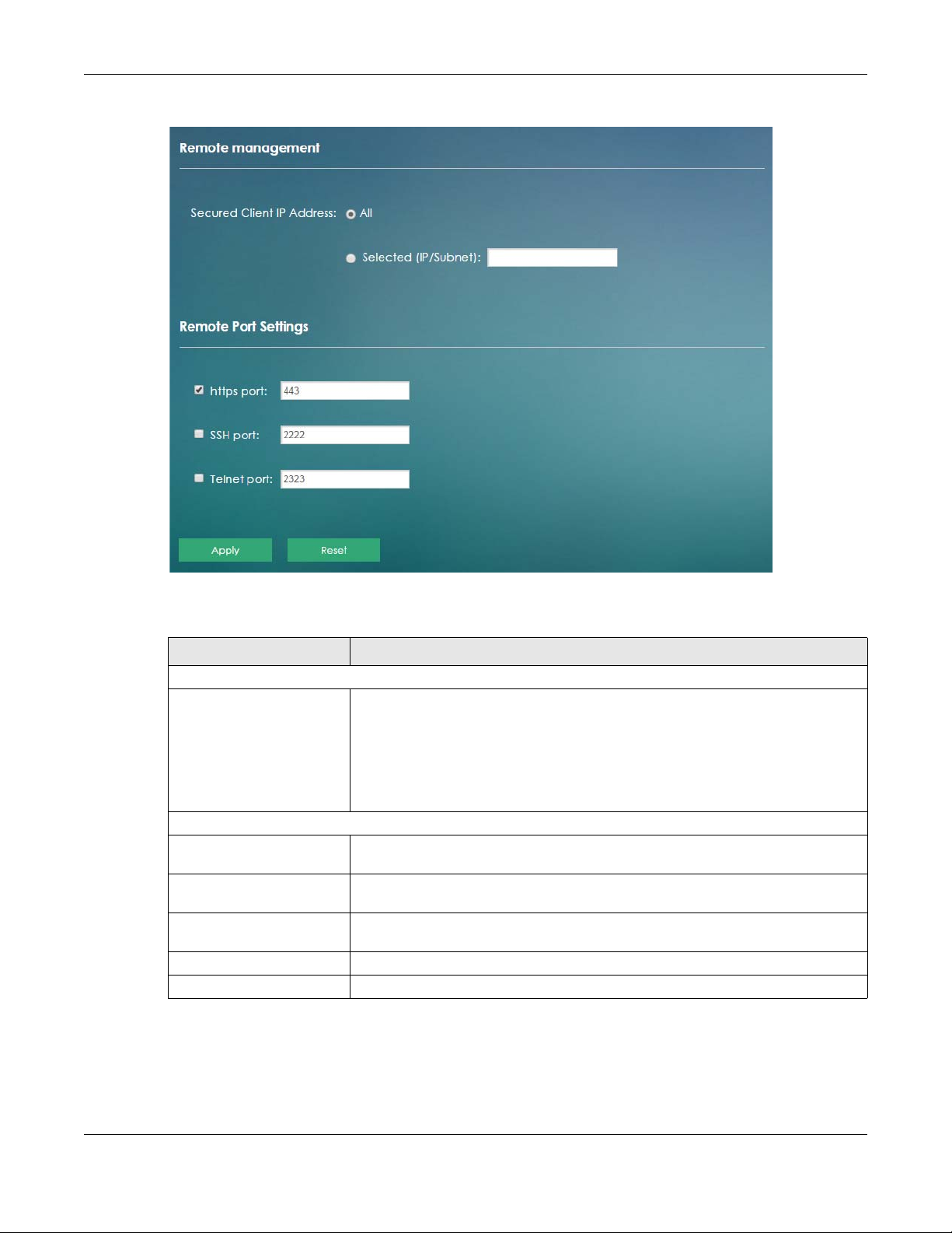
Chapter 7 Networking
Figure 61 Networking > Remote Management
The following table describes the labels in this screen.
Table 29 Networking > Remote Management
LABEL DESCRIPTION
Remote Management
Secured Client IP Address A secured client is a “trusted” computer that is allowed to communicate with the
LTE7460-M608 using HTTPS, SSH or Telnet service.
Select All to allow any computer to access the LTE7460-M608 using HTTPS, SSH or
Telnet service.
Use the Selected (IP/Subnet) field to specify an IP address that will access the
LTE7460-M608 using HTTPS, SSH or Telnet service.
Remote Port Settings
https port Select the check box to enable the access to the LTE7460-M608 using HTTPS service.
Enter the service port number for accessing the LTE7460-M608 using this service.
SSH port Select the check box to enable the access to the LTE7460-M608 using SSH service.
Telnet port Select the check box to enable the access to the LTE7460-M608 using Telnet service.
Apply Click Apply to save your changes back to the LTE7460-M608.
Reset Click Reset to reload the previous configuration for this screen.
Enter the service port number for accessing the LTE7460-M608 using this service.
Enter the service port number for accessing the LTE7460-M608 using this service.
Note: In Bridge mode, this screen is referred to as Port Management, see Section 7.2 on page
54 to learn more about your LTE7460’s operating modes.
LTE7460-M608 User’s Guide
77
Page 78

7.16 ICMP Screen
If an outside user attempts to probe an unsupported port on your LTE7460-M608, an Internet Control
Message Protocol (ICMP) response packet is automatically returned. This allows the outside user to know
the LTE7460-M608 exists. Your LTE7460-M608 supports anti-probing, which prevents the ICMP response
packet from being sent. This keeps outsiders from discovering your LTE7460-M608 when unsupported
ports are probed.
To change your LTE7460-M608’s security settings, click Networking > ICMP. The screen appears as shown.
Note: If you want your device to respond to pings and requests for unauthorized services, you
will also need to configure the firewall accordingly by disabling SPI.
Figure 62 Networking > ICMP
Chapter 7 Networking
The following table describes the labels in this screen.
Figure 63 Networking > ICMP
LABEL DESCRIPTION
ICMP Statements
Enable WAN Ping Respond The LTE7460-M608 will not respond to any WAN incoming Ping requests when Enable
Enable LAN Ping Respond The LTE7460-M608 will not respond to any LAN incoming Ping requests when Enable
Apply Click Apply to save your changes back to the LTE7460-M608.
Reset Click Reset to reload the previous configuration for this screen.
WAN Ping Respond is not selected. Select the check box to reply to incoming WAN
Ping requests.
LAN Ping Respond is not selected. Select the check box to reply to incoming LAN
Ping requests.
7.17 Technical Reference
This section provides some technical background information about the topics covered in this chapter.
7.17.1 About NAT
Inside/outside denotes where a host is located relative to the LTE7460-M608, for example, the computers
of your subscribers are the inside hosts, while the web servers on the Internet are the outside hosts.
LTE7460-M608 User’s Guide
78
Page 79
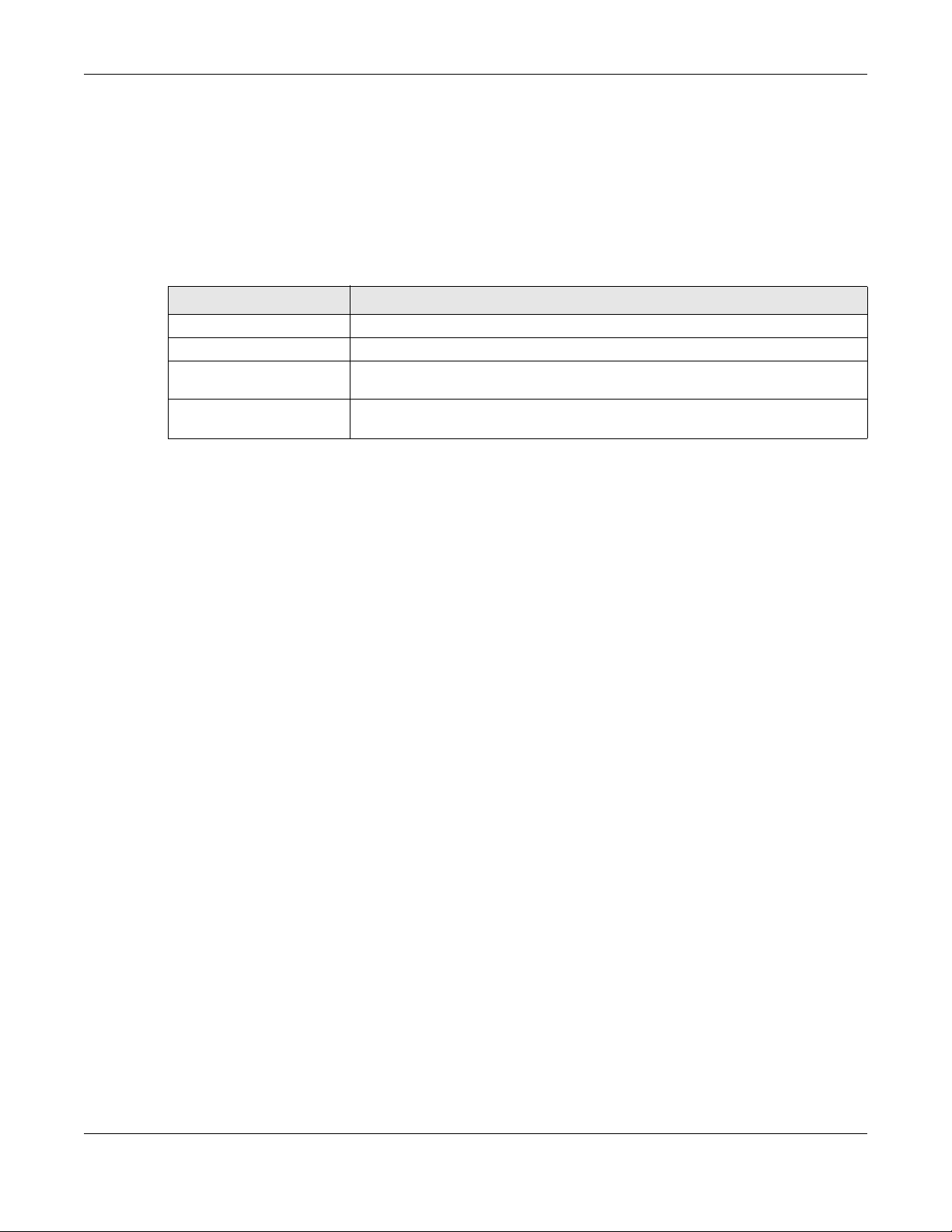
Chapter 7 Networking
Global/local denotes the IP address of a host in a packet as the packet traverses a router, for example,
the local address refers to the IP address of a host when the packet is in the local network, while the
global address refers to the IP address of the host when the same packet is traveling in the WAN side.
Note that inside/outside refers to the location of a host, while global/local refers to the IP address of a
host used in a packet. Thus, an inside local address (ILA) is the IP address of an inside host in a packet
when the packet is still in the local network, while an inside global address (IGA) is the IP address of the
same inside host when the packet is on the WAN side. The following table summarizes this information.
Table 30 NAT Definitions
ITEM DESCRIPTION
Inside This refers to the host on the LAN.
Outside This refers to the host on the WAN.
Local This refers to the packet address (source or destination) as the packet travels on the
LAN.
Global This refers to the packet address (source or destination) as the packet travels on the
NAT never changes the IP address (either local or global) of an outside host.
WAN.
What NAT Does
In the simplest form, NAT changes the source IP address in a packet received from a subscriber (the
inside local address) to another (the inside global address) before forwarding the packet to the WAN
side. When the response comes back, NAT translates the destination address (the inside global address)
back to the inside local address before forwarding it to the original inside host. Note that the IP address
(either local or global) of an outside host is never changed.
The global IP addresses for the inside hosts can be either static or dynamically assigned by the ISP. In
addition, you can designate servers, for example, a web server and a Telnet server, on your local
network and make them accessible to the outside world. If you do not define any servers, NAT offers the
additional benefit of firewall protection. With no servers defined, your LTE7460-M608 filters out all
incoming inquiries, thus preventing intruders from probing your network. For more information on IP
address translation, refer to RFC 1631, The IP Network Address Translator (NAT).
How NAT Works
Each packet has two addresses – a source address and a destination address. For outgoing packets,
the ILA (Inside Local Address) is the source address on the LAN, and the IGA (Inside Global Address) is
the source address on the WAN. For incoming packets, the ILA is the destination address on the LAN,
and the IGA is the destination address on the WAN. NAT maps private (local) IP addresses to globally
unique ones required for communication with hosts on other networks. It replaces the original IP source
address (and TCP or UDP source port numbers for Many-to-One and Many-to-Many Overload NAT
mapping) in each packet and then forwards it to the Internet. The LTE7460-M608 keeps track of the
original addresses and port numbers so incoming reply packets can have their original values restored.
The following figure illustrates this.
LTE7460-M608 User’s Guide
79
Page 80

7.17.2 About Firewall
SYN Attack
A SYN attack floods a targeted system with a series of SYN packets. Each packet causes the targeted
system to issue a SYN-ACK response. While the targeted system waits for the ACK that follows the SYNACK, it queues up all outstanding SYN-ACK responses on a backlog queue. SYN-ACKs are moved off the
queue only when an ACK comes back or when an internal timer terminates the three-way handshake.
Once the queue is full, the system will ignore all incoming SYN requests, making the system unavailable
for legitimate users.
DoS
Denials of Service (DoS) attacks are aimed at devices and networks with a connection to the Internet.
Their goal is not to steal information, but to disable a device or network so users no longer have access
to network resources. The LTE7460-M608 is pre-configured to automatically detect and thwart all known
DoS attacks.
DDoS
Chapter 7 Networking
A Distributed DoS (DDoS) attack is one in which multiple compromised systems attack a single target,
thereby causing denial of service for users of the targeted system.
LAND Attack
In a Local Area Network Denial (LAND) attack, hackers flood SYN packets into the network with a
spoofed source IP address of the target system. This makes it appear as if the host computer sent the
packets to itself, making the system unavailable while the target system tries to respond to itself.
Ping of Death
Ping of Death uses a "ping" utility to create and send an IP packet that exceeds the maximum 65,536
bytes of data allowed by the IP specification. This may cause systems to crash, hang or reboot.
SPI
Stateful Packet Inspection (SPI) tracks each connection crossing the firewall and makes sure it is valid.
Filtering decisions are based not only on rules but also context. For example, traffic from the WAN may
only be allowed to cross the firewall in response to a request from the LAN.
RFC 4890 SPEC Traffic
RFC 4890 specifies the filtering policies for ICMPv6 messages. This is important for protecting against
security threats including DoS, probing, redirection attacks and renumbering attacks that can be
carried out through ICMPv6. Since ICMPv6 error messages are critical for establishing and maintaining
communications, filtering policy focuses on ICMPv6 informational messages.
LTE7460-M608 User’s Guide
80
Page 81

Anti-Probing
If an outside user attempts to probe an unsupported port on your LTE7460-M608, an ICMP response
packet is automatically returned. This allows the outside user to know the LTE7460-M608 exists. The
LTE7460-M608 supports anti-probing, which prevents the ICMP response packet from being sent. This
keeps outsiders from discovering your LTE7460-M608 when unsupported ports are probed.
ICMP
Internet Control Message Protocol (ICMP) is a message control and error-reporting protocol between a
host server and a gateway to the Internet. ICMP uses Internet Protocol (IP) datagrams, but the messages
are processed by the TCP/IP software and directly apparent to the application user.
DoS Thresholds
For DoS attacks, the LTE7460-M608 uses thresholds to determine when to drop sessions that do not
become fully established. These thresholds apply globally to all sessions. You can use the default
threshold values, or you can change them to values more suitable to your security requirements.
7.17.2.1 Firewall Rules Overview
Chapter 7 Networking
Your customized rules take precedence and override the LTE7460-M608’s default settings. The LTE7460M608 checks the source IP address, destination IP address and IP protocol type of network traffic against
the firewall rules (in the order you list them). When the traffic matches a rule, the LTE7460-M608 takes the
action specified in the rule.
Firewall rules are grouped based on the direction of travel of packets to which they apply:
• LAN to Router • WAN to LAN
• LAN to WAN • WAN to Router
By default, the LTE7460-M608’s stateful packet inspection allows packets traveling in the following
directions:
• LAN to Router
These rules specify which computers on the LAN can manage the LTE7460-M608 (remote
management).
Note: You can also configure the remote management settings to allow only a specific
computer to manage the LTE7460-M608.
• LAN to WAN
These rules specify which computers on the LAN can access which computers or services on the
WAN.
By default, the LTE7460-M608’s stateful packet inspection drops packets traveling in the following
directions:
•WAN to LAN
These rules specify which computers on the WAN can access which computers or services on the
LAN.
LTE7460-M608 User’s Guide
81
Page 82

Chapter 7 Networking
Note: You also need to configure NAT port forwarding (or full featured NAT address mapping
rules) to allow computers on the WAN to access devices on the LAN.
•WAN to Router
By default the LTE7460-M608 stops computers on the WAN from managing the LTE7460-M608. You
could configure one of these rules to allow a WAN computer to manage the LTE7460-M608.
Note: You also need to configure the remote management settings to allow a WAN
computer to manage the LTE7460-M608.
You may define additional rules and sets or modify existing ones but please exercise extreme caution in
doing so.
For example, you may create rules to:
• Block certain types of traffic, such as IRC (Internet Relay Chat), from the LAN to the Internet.
• Allow certain types of traffic, such as Lotus Notes database synchronization, from specific hosts on the
Internet to specific hosts on the LAN.
• Allow everyone except your competitors to access a web server.
• Restrict use of certain protocols, such as Telnet, to authorized users on the LAN.
These custom rules work by comparing the source IP address, destination IP address and IP protocol
type of network traffic to rules set by the administrator. Your customized rules take precedence and
override the LTE7460-M608’s default rules.
7.17.2.2 Guidelines For Enhancing Security With Your Firewall
1 Change the default password via web configurator.
2 Think about access control before you connect to the network in any way.
3 Limit who can access your router.
4 Don't enable any local service (such as telnet or FTP) that you don't use. Any enabled service could
present a potential security risk. A determined hacker might be able to find creative ways to misuse the
enabled services to access the firewall or the network.
5 For local services that are enabled, protect against misuse. Protect by configuring the services to
communicate only with specific peers, and protect by configuring rules to block packets for the services
at specific interfaces.
6 Protect against IP spoofing by making sure the firewall is active.
7 Keep the firewall in a secured (locked) room.
7.17.2.3 Security Considerations
Note: Incorrectly configuring the firewall may block valid access or introduce security risks to
the LTE7460-M608 and your protected network. Use caution when creating or deleting
firewall rules and test your rules after you configure them.
Consider these security ramifications before creating a rule:
LTE7460-M608 User’s Guide
82
Page 83

Chapter 7 Networking
1 Does this rule stop LAN users from accessing critical resources on the Internet? For example, if IRC is
blocked, are there users that require this service?
2 Is it possible to modify the rule to be more specific? For example, if IRC is blocked for all users, will a rule
that blocks just certain users be more effective?
3 Does a rule that allows Internet users access to resources on the LAN create a security vulnerability? For
example, if FTP ports (TCP 20, 21) are allowed from the Internet to the LAN, Internet users may be able to
connect to computers with running FTP servers.
4 Does this rule conflict with any existing rules?
Once these questions have been answered, adding rules is simply a matter of entering the information
into the correct fields in the web configurator screens.
LTE7460-M608 User’s Guide
83
Page 84

Chapter 7 Networking
LTE7460-M608 User’s Guide
84
Page 85

8.1 Overview
This chapter shows you how to set up a contact list, send and view the text messages.
SMS (Short Message Service) allows you to send and view the text messages that the LTE7460-M608
received from mobile devices or the service provider.
When the SMS box is full the LTE7460-M608 will begin to delete older entries as it adds new ones.
8.1.1 What You Can Do in this Chapter
• Use the Applications > Contacts > Contact List screen to configure the contact list saved on the
LTE7460-M608 (Section 8.2 on page 85).
• Use the Applications > Contacts > SIM Contacts screen to view the contact list saved on the SIM card
(Section 8.3 on page 86).
• Use the Applications > Contacts > Contacts Settings screen to import or export the contacts files
(Section 8.4 on page 87).
• Use the Applications > Short Message > New SMS screen to send new messages (Section 8.5 on page
87).
• Use the Applications > Short Message > Inbox screen to view messages received on the LTE7460-M608
(Section 8.6 on page 88).
• Use the Applications > Short Message > Outbox screen to view messages sent from the LTE7460-M608
(Section 8.7 on page 89).
• Use the Applications > Short Message > Draft screen to view messages not yet sent from the LTE7460M608 (Section 8.8 on page 89).
• Use the Applications > Short Message > SIM SMS screen to view messages received on the SIM card
(Section 8.9 on page 90).
• Use the Applications > USSD screen to enter the USSD code for your LTE7460-M608 (Section 8.10 on
page 91).
CHAPTER 8
Applications
8.2 Contact List Screen
Use this screen to configure the contact list saved on the LTE7460-M608. To access this screen, click
Applications > Contacts > Contact List.
LTE7460-M608 User’s Guide
85
Page 86

Chapter 8 Applications
Figure 64 Applications > Contacts > Contact List
The following table describes the labels in this screen.
Table 31 Applications > Contacts > Contact List
LABEL DESCRIPTION
Contact List
Delete Select the check box next to the contact name and click Delete to remove the
New Click New to create a new entry.
Contact Name This field displays a descriptive name used to identify contacts.
Number This field displays the mobile phone number of contacts.
entry.
The number should begin with a + sign followed by the number’s country calling
code and the number, otherwise this number will not be useful.
Actions Click Edit to go to the screen where you can edit the contact details.
8.3 SIM Contacts Screen
Use this screen to view the contact list saved on the SIM card. To access this screen click Applications >
Contacts > SIM Contacts.
Figure 65 Applications > Contacts > SIM Contacts
The following table describes the labels in this screen.
Table 32 Applications > Contacts > SIM Contacts
LABEL DESCRIPTION
SIM Contacts
This field displays the index number of the contacts.
LTE7460-M608 User’s Guide
86
Page 87

Chapter 8 Applications
Table 32 Applications > Contacts > SIM Contacts
LABEL DESCRIPTION
Contact Name This field displays a descriptive name used to identify contacts.
Number This field displays the mobile phone number of contacts.
8.4 Contacts Settings Screen
Use this screen to import or export the contacts files. To access this screen, click Applications > Contacts
> Contacts Settings.
Figure 66 Applications > Contacts > Contacts Settings
The following table describes the labels in this screen.
Table 33 Applications > Contacts > Contacts Settings
LABEL DESCRIPTION
Import Contacts
Import from File Click Choose File to find the .csv file you want to upload. Remember that you must
Export Contact
Export to File A csv (comma-separated values) file is a way to store textual and numeric data. A
8.5 New SMS Screen
Use this screen to send messages using the LTE7460-M608. To access this screen, click Applications >
Short Message > New SMS.
decompress compressed (.zip) files before you can upload them.
You can select a .csv or .vcf file, then click Import to begin upload process.
vcard is an electronic business card, and it can store images and sound as well as
text.
Select a contact format from the drop-down list box to export your contacts. Click
Export to begin the download process
.
LTE7460-M608 User’s Guide
87
Page 88

Chapter 8 Applications
Type a phone number or click Add Receiver to select one from your Contact List. You can type up to
140 English characters (70 Chinese characters) in one message. If the message exceeds 140 English
characters, more than one message will be sent. The maximum number of SMS that can be sent is 8
(1000 English characters or 500 Chinese characters total). Click Send to send the message. Click Save to
store the message as a draft. Click Reset to reload the previous configuration for this screen.
Figure 67 Applications > Short Message > New SMS
8.6 Inbox Screen
Use this screen to view messages received on the LTE7460-M608. To access this screen, click Applications
> Short Message > Inbox.
Figure 68 Applications > Short Message > Inbox
LTE7460-M608 User’s Guide
88
Page 89

The following table describes the labels in this screen.
Table 34 Applications > Short Message > Inbox
LABEL DESCRIPTION
Inbox
Delete All Click Delete All to delete all messages.
From This field displays the name from which the message is sent.
Time This field displays the data and time the message was received.
Content This field displays the content of the message.
Action Click Delete to remove the message record.
8.7 Outbox Screen
Use this screen to view messages sent from the LTE7460-M608. To access this screen, click Applications >
Short Message > Outbox.
Chapter 8 Applications
This field displays the index number of the message.
Figure 69 Applications > Short Message > Outbox
The following table describes the labels in this screen.
Table 35 Applications > Short Message > Outbox
LABEL DESCRIPTION
Outbox
Delete All Click Delete All to delete all messages.
This field displays the index number of the message.
To This field displays the name the message is sent to.
Time This field displays the data and time the message was sent.
Content This field displays the content of the message.
Action Click Delete to remove the message record.
8.8 Draft Screen
Use this screen to view messages not yet sent from the LTE7460-M608. To access this screen, click
Applications > Short Message > Draft.
LTE7460-M608 User’s Guide
89
Page 90

Chapter 8 Applications
Figure 70 Applications > Short Message > Draft
The following table describes the labels in this screen.
Table 36 Applications > Short Message > Draft
LABEL DESCRIPTION
Draft
Delete All Click Delete All to delete all messages.
This field displays the index number of the message.
To This field displays the name the message is sent to.
Time This field displays the data and time the message was sent.
Content This field displays the content of the message.
Action Click Send to deliver the message.
Click Delete to remove the message record.
8.9 SIM SMS Screen
Use this screen to view messages received on the SIM card. To access this screen, click Applications >
Short Message > SIM SMS.
Figure 71 Applications > Short Message > SIM SMS
The following table describes the labels in this screen.
Table 37 Applications > Short Message > SIM SMS
LABEL DESCRIPTION
SIM SMST
Delete All Click Delete All to delete all messages.
From This field displays the name from which the message is sent.
Time This field displays the data and time the message was received.
This field displays the index number of the message.
LTE7460-M608 User’s Guide
90
Page 91

Table 37 Applications > Short Message > SIM SMS
LABEL DESCRIPTION
Content This field displays the content of the message.
Action Click Delete to remove the message record.
8.10 USSD Screen
Use this screen to enter an Unstructured Supplementary Service Data (USSD) code. The LTE7460-M608
sends this code to request different services or features to the Internet service provider. Click
Applications > USSD. Enter the code and click Send.
Figure 72 Applications > USSD
Chapter 8 Applications
LTE7460-M608 User’s Guide
91
Page 92

9.1 Overview
You can configure system settings, including the domain name and the inactivity time-out interval in the
System screen.
9.2 What You Can Do in This Chapter
• Use the System > System Information screen to view basic information about the LTE7460-M608 and
restart the LTE7460-M608 (Section 9.3 on page 92).
• Use the System > User Account screen to set the domain name and change the LTE7460-M608’s
system password (Section 9.4 on page 93).
• Use the System > Settings Profile screen to reset your device settings back to the factory default,
backup configuration and restoring configuration (Section 9.5 on page 95).
• Use the System > Firmware Upgrade screen to upload new firmware to your LTE7460-M608 (Section 9.6
on page 96).
• Use the System > Time Settings screen to change the LTE7460-M608’s time and date and configure
daylight saving time (Section 9.7 on page 97).
• Use the System > System Log screen to view logged messages and specify to where the LTE7460-M608
is to send logs (Section 9.8 on page 99).
• Use the System > Diagnostic screen to test a connection between devices and your LTE7460-M608
(Section 9.9 on page 101).
CHAPTER 9
System
9.3 The System Information Screen
Use this screen to view basic information about the LTE7460-M608 and restart the LTE7460-M608. To
access this screen, click System > System Information.
LTE7460-M608 User’s Guide
92
Page 93

Chapter 9 System
Figure 73 System > System Information
The following table describes the items in this screen.
Table 38 System > System Information
LABEL DESCRIPTION
About the 4G Routers
Firmware Version This displays the LTE7460-M608’s firmware version.
IMEI This displays the International Mobile Equipment Identity (IMEI) which is the serial
number of the built-in 3G module. IMEI is a unique 15-digit number used to identify a
mobile device.
Hardware Version This displays the LTE7460-M608’s hardware version.
Reboot Device
Reboot Device Click Reboot to restart the device. Wait a few minutes until the login screen appears.
If the login screen does not appear, type the IP address of the device in your Web
browser.
9.4 The User Account Screen
This screen allows you to set the domain name and change the LTE7460-M608’s system password. It is
strongly recommended that you change your LTE7460-M608's system password. To access this screen,
click System > User Account.
LTE7460-M608 User’s Guide
93
Page 94

Figure 74 System > User Account
Chapter 9 System
The following table describes the labels in this screen.
Table 39 System > User Account
LABEL DESCRIPTION
Login Web URL Setting
Web Domain Name Enter the domain name you want to give to the LTE7460-M608.
Apply Click Apply to save your changes back to the LTE7460-M608.
User Settings
Username Enter your username of the system account.
Password Type your new system password. Note that as you type a password, the screen
displays as dot (.) for each character you type.
Your password needs to be at least 6 ASCII characters long and should contain both
numbers and letters.
Confirm Password Type the new password again in this field.
Auto logout after Type how many minutes a management session can be left idle before the session
Apply Click Apply to save your changes back to the LTE7460-M608.
Reset Click Reset to reload the previous configuration for this screen.
times out. The default is 3 minutes. After it times out you have to log in with your
password again.
LTE7460-M608 User’s Guide
94
Page 95

Chapter 9 System
9.5 The Settings Profile Screen
The Settings Profile screen allows you to backup and restore device configurations. You can also reset
your device settings back to the factory default. To access this screen, click System > Settings Profile.
Figure 75 System > Settings Profile
9.5.1 Reset Settings
Click the Restore button to clear all user-entered configuration information and return the LTE7460-M608
to its factory defaults. The LTE7460-M608 automatically restarts.
You can also press the Reset button located next to the SIM card slot to reset the factory defaults of your
LTE7460-M608.
9.5.2 Save Current Settings
Enter the profile name you specified in the New Profile Name field, and click Save. The profile you saved
will be displayed in the Profile List field.
LTE7460-M608 User’s Guide
95
Page 96

Chapter 9 System
The following table describes the labels in this screen.
Table 40 System > Settings Profile
LABEL DESCRIPTION
Profile List
This field displays the index number of the profile.
Profile Name This field displays the profile name you specified in the New Profile Name field.
Saved Date This displays the saved time and date of the profile.
Action Click Apply to use the configuration to the LTE7460-M608.
Click Delete to go to the screen where you can remove the profile.
9.5.3 Import and Export Settings Profile
This screen allows you to upload a new or previously saved configuration file from your computer to your
LTE7460-M608.
Type in the location of the file you want to upload in the Apply Profile from File field or click Choose File
to find it. Click Apply to begin the upload process. The LTE7460-M608 automatically restarts.
Do not turn off the LTE7460-M608 while configuration file upload is in
progress.
Backup Configuration allows you to back up (save) the LTE7460-M608’s current configuration to a file on
your computer. The configuration file should be saved and edited in UTF-8 (without BOM) format, if
you’re using Windows Notepad, make sure you choose File > Save as UTF-8 in the text editor. Once your
LTE7460-M608 is configured and functioning properly, it is highly recommended that you back up your
configuration file before making configuration changes. The backup configuration file will be useful in
case you need to return to your previous settings.
Select one profile from the drop-down list box in the Export Profile to File field, and click Export to save
the LTE7460-M608’s current configuration to your computer.
After the LTE7460-M608 configuration has been restored successfully, the login screen appears. If you
uploaded the default configuration file you may need to change the IP address of your computer to be
in the same subnet as that of the default device IP address (192.168.1.1).
9.6 The Firmware Upgrade Screen
This screen allows you to upload new firmware to your LTE7460-M608. You can download new firmware
releases from your nearest Zyxel FTP site (or www.zyxel.com) to use to upgrade your device’s
performance.
Only use firmware for your device’s specific model.
To access this screen, click System > Firmware Upgrade. This screen displays the current firmware version
and status of the LTE7460-M608. Type in the location of the file you want to upload in the Select Firmware
File field or click Choose File to find it. Remember that you must decompress compressed (.ZIP) files
LTE7460-M608 User’s Guide
96
Page 97

Chapter 9 System
before you can upload them. You can select the check box to return the LTE7460-M608 to its factory
defaults after upgrading the new firmware. Click Apply to begin the upload process.
The upload process uses HTTP (Hypertext Transfer Protocol) and may take up to two minutes. After a
successful upload, the system will reboot.
Do NOT turn off the LTE7460-M608 while firmware upload is in progress!
Figure 76 System > Firmware Upgrade
9.7 The Time Settings Screen
For effective scheduling and logging, the LTE7460-M608 system time must be accurate. The LTE7460M608 has a software mechanism to get the current time and date from an external server. To change
your LTE7460-M608’s time zone, click System > Time Settings. The screen displays as shown. You can have
the LTE7460-M608 get the date and time from a time server or change the IP address or URL of your time
server.
LTE7460-M608 User’s Guide
97
Page 98

Figure 77 System > Time Settings
Chapter 9 System
The following table describes the labels in this screen.
Table 41 System > Time Settings
LABEL DESCRIPTION
Date & Time
Device Time This field displays the present time and date of your LTE7460-M608.
LTE7460-M608 User’s Guide
98
Page 99

Chapter 9 System
Table 41 System > Time Settings
LABEL DESCRIPTION
Set Automatically Select Prefer Cellular Service Time to have the LTE7460-M608 get the time and date
from the cellular service server.
Select Prefer NTP server to have the LTE7460-M608 get the time and date from the
time server you specify.
NTP Server
Time Zone Choose the time zone of your location. This will set the time difference between your
time zone and Greenwich Mean Time (GMT).
NTP Server 1~5 Enter the IP address or URL of your time server. Check with your ISP/network
Daylight Saving Time
Enable Daylight Saving Time Daylight saving is a period from late spring to early fall when many countries set their
Apply Click Apply to save your changes back to the LTE7460-M608.
Reset Click Reset to reload the previous configuration for this screen.
administrator if you are unsure of this information.
clocks ahead of normal local time by one hour to give more daytime light in the
evening. Select this option if you use Daylight Saving Time.
9.8 The System Log Screen
Use this screen to specify which logs to display and to where the LTE7460-M608 is to send logs. To access
this screen, click System > System Log.
LTE7460-M608 User’s Guide
99
Page 100

Figure 78 System > System Log
Chapter 9 System
The following table describes the labels in this screen.
Table 42 System > System Log
LABEL DESCRIPTION
System Log
Enable Log Select the check box to enable system logging.
Log Level Select the level of the logs that the LTE7460-M608 is to record and send to the syslog
server.
The LTE7460-M608 displays and records the logs with the level equal to or higher than
what you selected.
Functional Log Select the function type of the logs that the LTE7460-M608 is to record and send to
the syslog server.
LTE7460-M608 User’s Guide
100
 Loading...