

Zebra LS4208 Product Reference Manual

LS4208
Product Reference Guide


LS4208
Product Reference Guide
72E-69413-08
Revision A
March 2015

ii LS4208 Product Reference Guide
© 2015 ZIH Corp and/or its affiliates. All rights reserved.
No part of this publication may be reproduced or used in any form, or by any electrical or mechanical means,
without permission in writing from Zebra. This includes electronic or mechanical means, such as photocopying,
recording, or information storage and retrieval systems. The material in this ma nual is subject to change
without notice.
The software is provided strictly on an “as i s” basis. All sof twar e, including firmware, furnished to the user is on
a licensed basis. Zebra grants to the user a non-transferable and non-exclusive license to use each software
or firmware program delivered hereunder (licensed program) . Except as n oted below, such license may not be
assigned, sublicensed, or otherwise tran sfe rr e d by th e user without prior written consent of Zebra. No right to
copy a licensed program in whole or in part is granted, exce pt as permitted unde r copyright law. The user shall
not modify , merge, or incorporate any for m or portion of a licensed program with other pro gram material, create
a derivative work from a licensed program , or us e a li censed program in a network without written permission
from Zebra. The user agrees to maintain Zebra’s copyright notice on the licensed programs delivered
hereunder , and to include the same on any authorized copies it makes, in whole or in part. The user agrees not
to decompile, disassemble, decode, or reverse engineer any licensed program delivered to the user or any
portion thereof.
Zebra reserves the right to make changes to any software or product to improve reliability, function, or design.
Zebra does not assume any product liability arising out of, or in connection with, the application or use of any
product, circuit, or application described herein.
No license is granted, either expressly or by implication, estoppel, or otherwise under any Zebra Technologies
Corporation, intellectual property rights. An implied license only exists for equipment, circuits, and subsystems
contained in Zebra products.
Zebra and the stylized Zebra head are trademarks of ZIH Corp., registered in many jurisdictions worldwide. All
other trademarks are the property of their respective owners.
Zebra Technologies Corporation
Lincolnshire, IL U.S.A.
http://www.zebra.com
Warranty
For the complete Zebra hardware product warranty statement, go to:
http://www.zebra.com/warranty.

Revision History
Changes to the original manual are listed below:
Change Date Description
-01 Rev A 5/2005 Initial release.
-02 Rev A 6/2005 Update RSS description.
-03 Rev A 1/2007 Update service section, add special IBM command bar codes, add parameter bar
-04 Rev A 6/2007 Add information for LS4208PR version, which supports PDF417.
-05 Rev A 7/2007 Add note to end of Wand Emulation chapter regarding error beep emitted when
-06 Rev A 4/2009 Add Parameter Scanning option, add Simple COM Port Emulation to USB device
iii
codes for Bookland ISBN format and new UPC supplemental decode options, add
bar codes for report version, report MIMIC version, and report Synapse cable, add
ADF section.
scanner attempts to send composite data.
type parameter, add new ADF options.
-07 Rev A 11/2012 Removed patents, and Regulatory specs; updated URLs, ambient light tolerance,
and 123Scan
-08 Rev A 3/2015 Zebra Rebranding
2
chapter.

iv LS4208 Product Reference Guide

Table of Contents
Warranty........................................................................................................................ ii
Revision History............................................................................................................. iii
About This Guide
Introduction.................................................................................................................... xiii
Notational Conventions.................................................................................................. xiv
Related Documents....................................................................................................... xiv
Service Information........................................................................................................ xv
Chapter 1: Getting Started
Introduction ................................................................................................................... 1-1
Unpacking ..................................................................................................................... 1-2
Setting Up the Scanner ................................................................................................. 1-3
Installing the Interface Cable .................................................................................. 1-3
Removing the Interface Cable ................................................................................ 1-4
Connecting a Synapse Cable Interface .................................................................. 1-4
Connecting Power (if required) ............................................................................... 1-4
Configuring the Scanner ......................................................................................... 1-5
Chapter 2: Scanning
Introduction ................................................................................................................... 2-1
Beeper Definitions ........................................................................................................ 2-2
LED Definitions ............................................................................................................. 2-3
Scan Patterns ............................................................................................................... 2-4
Single-Line Only ...................................................................................................... 2-4
Multi-Line Smart Raster .......................................................................................... 2-4
Multi-line Always Raster .......................................................................................... 2-4
Scanning Modes ........................................................................................................... 2-5
Scanning in Hand-Held Mode ................................................................................. 2-5
Scanning in Hands-Free Mode ............................................................................... 2-9
LS4208 Decode Zone ................................................................................................... 2-11

vi LS4208 Product Reference Guide
Chapter 3: Maintenance, Troubleshooting & Technical Specifications
Introduction ................................................................................................................... 3-1
Maintenance ................................................................................................................. 3-1
Troubleshooting ............................................................................................................ 3-2
Technical Specifications ............................................................................................... 3-5
Scanner Signal Descriptions ......................................................................................... 3-7
Chapter 4: User Preferences
Introduction ................................................................................................................... 4-1
Scanning Sequence Examples ..................................................................................... 4-1
Errors While Scanning .................................................................................................. 4-1
User Preferences Parameter Defaults .......................................................................... 4-2
User Preferences .......................................................................................................... 4-3
Default Parameters ................................................................................................. 4-3
Parameter Bar Code Scanning ............................................................................... 4-4
Beeper Tone ........................................................................................................... 4-4
Beeper Volume ....................................................................................................... 4-5
Power Mode ............................................................................................................ 4-5
Scan Pattern ........................................................................................................... 4-6
Scan Line Width ...................................................................................................... 4-7
Raster Height .......................................................................................................... 4-8
Laser On Time ........................................................................................................ 4-9
Beep After Good Decode ........................................................................................ 4-9
PDF Decode Feedback ........................................................................................... 4-10
Chapter 5: Keyboard Wedge Interface
Introduction ................................................................................................................... 5-1
Connecting a Keyboard Wedge Interface ..................................................................... 5-2
Keyboard Wedge Parameter Defaults .......................................................................... 5-3
Keyboard Wedge Host Parameters .............................................................................. 5-4
Keyboard Wedge Host Types ................................................................................. 5-4
Keyboard Wedge Country Types (Country Codes) ................................................ 5-5
Ignore Unknown Characters ................................................................................... 5-6
Keystroke Delay ...................................................................................................... 5-7
Intra-Keystroke Delay ............................................................................................. 5-7
Alternate Numeric Keypad Emulation ..................................................................... 5-8
Caps Lock On ......................................................................................................... 5-8
Caps Lock Override ................................................................................................ 5-9
Convert Wedge Data .............................................................................................. 5-10
Function Key Mapping ............................................................................................ 5-10
FN1 Substitution ..................................................................................................... 5-11
Send Make and Break ............................................................................................ 5-11
Keyboard Maps ....................................................................................................... 5-12
ASCII Character Set for Keyboard Wedge ................................................................... 5-13

Chapter 6: RS-232 Interface
Introduction ................................................................................................................... 6-1
Connecting an RS-232 Interface .................................................................................. 6-2
RS-232 Parameter Defaults .......................................................................................... 6-3
RS-232 Host Parameters .............................................................................................. 6-4
RS-232 Host Types ................................................................................................. 6-6
Baud Rate ............................................................................................................... 6-7
Parity ....................................................................................................................... 6-8
Stop Bit Select ........................................................................................................ 6-9
Data Bits (ASCII Format) ........................................................................................ 6-9
Check Receive Errors ............................................................................................. 6-10
Hardware Handshaking .......................................................................................... 6-10
Software Handshaking ............................................................................................ 6-12
Host Serial Response Time-out .............................................................................. 6-14
RTS Line State ........................................................................................................ 6-15
Beep on <BEL> ....................................................................................................... 6-15
Intercharacter Delay ................................................................................................ 6-16
Nixdorf Beep/LED Options ...................................................................................... 6-17
Ignore Unknown Characters ................................................................................... 6-17
ASCII Character Set for RS-232 ................................................................................... 6-18
Table of Contents vii
Chapter 7: USB Interface
Introduction ................................................................................................................... 7-1
Connecting a USB Interface ......................................................................................... 7-2
USB Parameter Defaults .............................................................................................. 7-4
USB Host Parameters .................................................................................................. 7-5
USB Device Type .................................................................................................... 7-5
USB Country Keyboard Types (Country Codes) .................................................... 7-6
USB Keystroke Delay ............................................................................................. 7-8
USB CAPS Lock Override ...................................................................................... 7-8
USB Ignore Unknown Characters ........................................................................... 7-9
Emulate Keypad ...................................................................................................... 7-9
USB Keyboard FN 1 Substitution ............................................................................ 7-10
Function Key Mapping ............................................................................................ 7-10
Simulated Caps Lock .............................................................................................. 7-11
Convert Case .......................................................................................................... 7-11
ASCII Character Set for USB ........................................................................................ 7-12
Chapter 8: IBM Interface
Introduction ................................................................................................................... 8-1
Connecting to an IBM 468X/469X Host ........................................................................ 8-2
IBM Parameter Defaults ............................................................................................... 8-3
IBM 468X/469X Host Parameters ................................................................................. 8-4
Port Address ........................................................................................................... 8-4
Convert Unknown to Code 39 ................................................................................. 8-5
Optional IBM Parameters ............................................................................................. 8-6
Ignore Beep ............................................................................................................ 8-6
Ignore Bar Code Configuration ............................................................................... 8-6

viii LS4208 Product Reference Guide
Chapter 9: Wand Emulation Interface
Introduction ................................................................................................................... 9-1
Connecting Using Wand Emulation .............................................................................. 9-2
Wand Emulation Parameter Defaults ........................................................................... 9-3
Wand Emulation Host Parameters ............................................................................... 9-4
Wand Emulation Host Types .................................................................................. 9-4
Leading Margin (Quiet Zone) .................................................................................. 9-5
Polarity .................................................................................................................... 9-6
Ignore Unknown Characters ................................................................................... 9-6
Convert All Bar Codes to Code 39 .......................................................................... 9-7
Convert Code 39 to Full ASCII ............................................................................... 9-8
Chapter 10: Scanner Emulation Interface
Introduction ................................................................................................................... 10-1
Connecting Using Scanner Emulation .......................................................................... 10-2
Scanner Emulation Parameter Defaults ....................................................................... 10-3
Scanner Emulation Host ............................................................................................... 10-4
Scanner Emulation Host Parameters ........................................................................... 10-4
Beep Style ............................................................................................................... 10-4
Parameter Pass-Through ........................................................................................ 10-5
Convert Newer Code Types .................................................................................... 10-6
Module Width .......................................................................................................... 10-7
Convert All Bar Codes to Code 39 .......................................................................... 10-7
Code 39 Full ASCII Conversion .............................................................................. 10-8
Transmission Timeout ............................................................................................. 10-9
Ignore Unknown Characters ................................................................................... 10-10
Leading Margin ....................................................................................................... 10-10
Check For Decode LED .......................................................................................... 10-11
Chapter 11: 123Scan
Introduction ................................................................................................................... 11-1
Communication with 123Scan2 .................................................................................... 11-1
123Scan2 Requirements .............................................................................................. 11-2
Chapter 12: Symbologies
Introduction ................................................................................................................... 12-1
Scanning Sequence Examples ..................................................................................... 12-1
Errors While Scanning .................................................................................................. 12-2
Symbology Parameter Defaults .................................................................................... 12-2
UPC/EAN ...................................................................................................................... 12-6
Enable/Disable UPC-A/UPC-E ............................................................................... 12-6
Enable/Disable UPC-E1 .......................................................................................... 12-7
Enable/Disable EAN-13/EAN-8 ............................................................................... 12-8
Enable/Disable Bookland EAN ............................................................................... 12-9
Decode UPC/EAN/JAN Supplementals .................................................................. 12-9
UPC/EAN/JAN Supplemental Redundancy ............................................................ 12-14
Transmit UPC-A Check Digit .................................................................................. 12-14

Table of Contents ix
Transmit UPC-E Check Digit .................................................................................. 12-15
Transmit UPC-E1 Check Digit ................................................................................ 12-15
UPC-A Preamble .................................................................................................... 12-16
UPC-E Preamble .................................................................................................... 12-17
UPC-E1 Preamble .................................................................................................. 12-18
Convert UPC-E to UPC-A ....................................................................................... 12-19
Convert UPC-E1 to UPC-A ..................................................................................... 12-19
EAN-8/JAN-8 Extend .............................................................................................. 12-20
Bookland ISBN Format ........................................................................................... 12-21
UCC Coupon Extended Code ................................................................................. 12-22
Code 128 ...................................................................................................................... 12-23
Enable/Disable Code 128 ....................................................................................... 12-23
Enable/Disable GS1-128 (formerly UCC/EAN-128) ................................................ 12-23
Enable/Disable ISBT 128 ........................................................................................ 12-24
Code 39 ........................................................................................................................ 12-25
Enable/Disable Code 39 ......................................................................................... 12-25
Enable/Disable Trioptic Code 39 ............................................................................ 12-25
Convert Code 39 to Code 32 .................................................................................. 12-26
Code 32 Prefix ........................................................................................................ 12-26
Set Lengths for Code 39 ......................................................................................... 12-27
Code 39 Check Digit Verification ............................................................................ 12-28
Transmit Code 39 Check Digit ................................................................................ 12-29
Code 39 Full ASCII Conversion .............................................................................. 12-30
Code 39 Buffering (Scan & Store) .......................................................................... 12-31
Code 93 ........................................................................................................................ 12-34
Enable/Disable Code 93 ......................................................................................... 12-34
Set Lengths for Code 93 ......................................................................................... 12-34
Code 11 ........................................................................................................................ 12-36
Code 11 .................................................................................................................. 12-36
Set Lengths for Code 11 ......................................................................................... 12-36
Code 11 Check Digit Verification ............................................................................ 12-38
Transmit Code 11 Check Digits .............................................................................. 12-39
Interleaved 2 of 5 (ITF) ................................................................................................. 12-40
Enable/Disable Interleaved 2 of 5 ........................................................................... 12-40
Set Lengths for Interleaved 2 of 5 ........................................................................... 12-40
I 2 of 5 Check Digit Verification ............................................................................... 12-42
Transmit I 2 of 5 Check Digit ................................................................................... 12-43
Convert I 2 of 5 to EAN-13 ...................................................................................... 12-43
Discrete 2 of 5 (DTF) .................................................................................................... 12-44
Enable/Disable Discrete 2 of 5 ................................................................................ 12-44
Set Lengths for Discrete 2 of 5 ............................................................................... 12-44
Chinese 2 of 5 ............................................................................................................... 12-46
Enable/Disable Chinese 2 of 5 ................................................................................ 12-46
Codabar (NW - 7) ......................................................................................................... 12-47
Enable/Disable Codabar ......................................................................................... 12-47
Set Lengths for Codabar ......................................................................................... 12-47
CLSI Editing ............................................................................................................ 12-49
NOTIS Editing ......................................................................................................... 12-49
MSI ............................................................................................................................... 12-50
Enable/Disable MSI ................................................................................................ 12-50

x LS4208 Product Reference Guide
Set Lengths for MSI ................................................................................................ 12-50
MSI Check Digits .................................................................................................... 12-51
Transmit MSI Check Digit(s) ................................................................................... 12-52
MSI Check Digit Algorithm ...................................................................................... 12-52
GS1 DataBar (formerly RSS - Reduced Space Symbology) ........................................ 12-53
Convert GS1 DataBar to UPC/EAN ........................................................................ 12-54
PDF417/MicroPDF417 .................................................................................................. 12-55
Enable/Disable PDF417 .......................................................................................... 12-55
Enable/Disable MicroPDF417 ................................................................................. 12-55
MicroPDF Performance .......................................................................................... 12-56
Transmit Symbols in Codeword Format .................................................................. 12-57
Transmit Unknown Codewords ............................................................................... 12-58
Escape Characters ................................................................................................. 12-58
Delete Character Set ECIs ...................................................................................... 12-59
Composite Codes ......................................................................................................... 12-60
Composite CC-C ..................................................................................................... 12-60
Composite CC-A/B .................................................................................................. 12-60
UPC Composite Mode ............................................................................................ 12-61
Composite Beep Mode ........................................................................................... 12-62
Symbology - Specific Security Levels ........................................................................... 12-63
Redundancy Level .................................................................................................. 12-63
Security Level ......................................................................................................... 12-65
Bi-directional Redunda\ncy ..................................................................................... 12-66
Intercharacter Gap ........................................................................................................ 12-66
Chapter 13: Miscellaneous Scanner Options
Introduction ................................................................................................................... 13-1
Scanning Sequence Examples ..................................................................................... 13-1
Errors While Scanning .................................................................................................. 13-1
Miscellaneous Parameter Defaults ............................................................................... 13-2
Miscellaneous Scanner Parameters ............................................................................. 13-3
Transmit Code ID Character ................................................................................... 13-3
Prefix/Suffix Values ................................................................................................. 13-3
Scan Data Transmission Format ............................................................................ 13-4
FN1 Substitution Values ......................................................................................... 13-6
Transmit “No Read” Message ................................................................................. 13-6
Synapse Interface ................................................................................................... 13-7
Report Version ........................................................................................................ 13-8
Report Synapse Cable ............................................................................................ 13-8
Chapter 14: Advanced Data Formatting
Introduction ................................................................................................................... 14-1
Rules: Criteria Linked to Actions ................................................................................... 14-1
Using ADF Bar Codes .................................................................................................. 14-2
ADF Bar Code Menu Example ..................................................................................... 14-2
Rule 1: The Code 128 Scanning Rule .................................................................... 14-3
Rule 2: The UPC Scanning Rule ............................................................................ 14-3
Alternate Rule Sets ................................................................................................. 14-3

Table of Contents xi
Rules Hierarchy (in Bar Codes) .............................................................................. 14-4
Default Rules .......................................................................................................... 14-5
ADF Bar Codes ............................................................................................................. 14-5
Special Commands ....................................................................................................... 14-8
Pause Duration ....................................................................................................... 14-8
Begin New Rule ...................................................................................................... 14-8
Save Rule ............................................................................................................... 14-8
Erase ....................................................................................................................... 14-9
Quit Entering Rules ................................................................................................. 14-9
Disable Rule Set ..................................................................................................... 14-10
Criteria .......................................................................................................................... 14-11
Code Types ............................................................................................................. 14-11
Code Lengths .......................................................................................................... 14-15
Message Containing A Specific Data String ........................................................... 14-19
Actions .......................................................................................................................... 14-23
Send Data ............................................................................................................... 14-23
Setup Field(s) .......................................................................................................... 14-26
Modify Data ............................................................................................................. 14-33
Pad Data with Spaces ............................................................................................. 14-34
Pad Data with Zeros ............................................................................................... 14-38
Beeps ...................................................................................................................... 14-42
Send Keystroke (Control Characters and Keyboard Characters) ........................... 14-43
Send Right Control Key .......................................................................................... 14-75
Send Graphic User Interface (GUI) Characters ...................................................... 14-76
Turn On/Off Rule Sets ............................................................................................ 14-82
Alphanumeric Keyboard ............................................................................................... 14-83
Appendix A: Standard Default Parameters
Default Parameters ....................................................................................................... A-1
Appendix B: Programming References
Symbol Code Identifiers ................................................................................................ B-1
AIM Code Identifiers ..................................................................................................... B-2
Appendix C: Sample Bar Codes
Code 39 ........................................................................................................................ C-1
UPC/EAN ...................................................................................................................... C-1
UPC-A, 100% .......................................................................................................... C-1
EAN-13, 100% ........................................................................................................ C-2
Code 128 ...................................................................................................................... C-2
Interleaved 2 of 5 .......................................................................................................... C-2
GS1 DataBar ................................................................................................................ C-3
GS1 DataBar ........................................................................................................... C-3
GS1 DataBar-14 ..................................................................................................... C-4

xii LS4208 Product Reference Guide
Appendix D: Numeric Bar Codes
Numeric Bar Codes ...................................................................................................... D-1
Cancel ........................................................................................................................... D-3
Appendix E: ASCII Character Sets
Index
Tell Us What You Think...

About This Guide
Introduction
The LS4208 Product Reference Guide provides general instructions for setting up, operating, maintaining, and
troubleshooting the LS4208 scanner. The scanner includes the following variations of the scanner:
•
LS4208-SR: Standard version
•
LS4208-PR: PDF417 version
Chapter Descriptions
•
Chapter 1, Getting Started provides a product overview, unpacking instructions, and cable connection
information.
•
Chapter 2, Scanning describes part s of the scanne r , b eeper and LED definitions, and h ow to use the scanner
in hand-held and hands-free modes.
•
Chapter 3, Maintenance, Troubleshooting & Technical Specifications provides information on how to care for
the scanner, troubleshooting, and technical specifications.
•
Chapter 4, User Preferences provides programming bar codes for selecting user preference features for the
scanner.
•
Chapter 5, Keyboard Wedge Interface provides information for setting up the sc an ne r fo r Keyb o ar d Wedge
operation.
•
Chapter 6, RS-232 Interface provides information for setting up the scanner for RS-232 operation.
•
Chapter 7, USB Interface provides information for setting up the scanner for USB operation.
•
Chapter 8, IBM Interface provides all information for setting up the scanner with IBM 468X/469X POS
systems.
•
Chapter 9, Wand Emulation Interface provides all info rmation for setting up the scanner for Wand Emulation
operation.
•
Chapter 10, Scanner Emulation Interface provides information for setting up the scanner for Scanner
Emulation operation.
•
Chapter 11, 123Scan (PC based scanner configuration tool) provides the bar code that must be scanned to
communicate with the 123Scan program.

xiv LS4208 Product Reference Guide
*Baud Rate 9600
Feature/Option
* Indicates Default
•
Chapter 12, Symbologies describes all symbology features and provides the programming bar codes
necessary for selecting these features for the scanner.
•
Chapter 13, Miscellaneous Scanner Option s includes commonly used bar codes to customize how the data
is transmitted to the host device.
•
Chapter 14, Advanced Data Formatting details Advanced Data Formatting (ADF), a means of customizing
data before transmission to a host device.
•
Appendix A, Standard Defaul t Parameters provides a table of all host devices and miscellaneous scanne r
defaults.
•
Appendix B, Programming References provides a table of AIM cod e identifiers, ASCII character conversions,
and keyboard maps.
•
Appendix C, Sample Bar Codes includes sample bar codes.
•
Appendix D, Numeric Bar Codes includes the numeric bar codes to scan for parameters requiring specific
numeric values.
•
Appendix E, ASCII Character Sets provides ASCII character value tables.
Notational Conventions
The following conventions are used in this document:
•
Bullets indicate:
• action items
• lists of alternatives
• lists of required steps that are not necessarily sequential
•
Sequential lists (e.g., those that describe step-by-s te p pr oc ed ur e s) ap pe a r as nu m be re d lists.
•
Throughout the programming bar code menus, asterisks (*) are used to denote default parameter settings.
Related Documents
The following documents provide more information for the LS4208 scanner:
For the latest version of this guide and all guides, go to:http://www.zebra.com/support.
•
The LS4208 Quick Reference Guide (p/n 72-69411-xx) provides general information to help the user get
started with the scanner. It includes basic operation instructions and start up bar codes.

Service Information
If you have a problem using the equipment, contact your facility's technical or systems support. If there is a
problem with the equipment, they will contact the Zebra Global Customer Support Center at:
http://www.zebra.com/support.
When contacting Zebra support, please have the following information available:
•
Serial number of the unit
•
Model number or product name
•
Software type and version number
Zebra responds to calls by e-mail, telephone or fax within the time limits set forth in service agreements. If your
problem cannot be solved by Zebra support, you may need to return your equipment for servicing and will be given
specific directions. Zebra is not responsible for any damages incurred during shipment if the approved shipping
container is not used. Shipping the units improperly can possibly void the warranty.
If you purchased your business product from a Zebra business partner, please contact that business partner for
support.
About This Guide xv

xvi LS4208 Product Reference Guide

Chapter 1 Getting Started
Introduction
The scanner combines excellent scanning performance and advanced ergonomics to provide the best value in a
lightweight laser scanner. Whether used as a hand-held scanner or in hands-free mode in a stand, the scanner
ensures comfort and ease of use for extended periods of time.
In addition to single-line laser scanning, the scanner supports multi-line rastering. Multi-line rastering allows the
scanner to capture stacked GS1 DataBar codes (formerly Redu ced S pace Symbology/RSS) and increases an gular
tolerances, minimizing product orientation and hand movements. Multi-line rastering also allows the scanner to
read poor quality bar codes. For more information about scanning modes and stacked GS1 DataBar codes, see
Scan Pattern on page 4-6 and GS1 DataBar on page C-3.
NOTE Only the LS4208-PR version supports PDF417 bar codes and variants.
Figure 1-1
LS4208 Scanner

1 - 2 LS4208 Product Reference Guide
This scanner supports the following interfaces:
•
Keyboard Wedge connection to a host. The host interprets scanned data as keystrokes. This interface
supports the following international keyboards (for Windows
French, French Canadian, Spanish, Italian, Swedish, UK English, Portuguese-Brazilian, and Japanese.
•
Stan dard RS-232 connection to a host. Scan bar code menus to set up pr oper communication o f the scanner
with the host.
•
USB connection to a host. The scanner autodetects a USB host and defaults to the HID keyboard interface
type. Select other USB interface types by scanning prog ramming bar code menu s.This interface support s the
following international keyboards (for Windows
Canadian, Spanish, Italian, Swedish, UK English, Portuguese-Brazilian, and Japanese.
•
Connection to IBM® 468X/469X hosts. Scan bar code menus to set up communication of the scanner with
the IBM terminal.
•
Wand Emulation connection to a host. The scanner is co nnected to a portable data terminal, a controller, or
host which collects the data as wand data and decodes it.
•
Scanner Emulation connection to a host. The scanner is connected to a portable data terminal, a controller
which collects the data and interprets it for the host.
®
environment): North America, German,
®
environment): North America, German, French, French
•
Synapse capability which allows connection to a wide variety of host systems using a Synapse and Synapse
adapter cable. The scanner autodetects the host.
•
Configuration via 123Scan.
Unpacking
Remove the scanner from its packing and inspect it for damage. If the scanner was damaged in transit, contact
Zebra Mobility Support. See page xv for contact information. KEEP THE PACKING. It is the approved shipping
container and should be used if the equipment ever needs to be return for servicing.
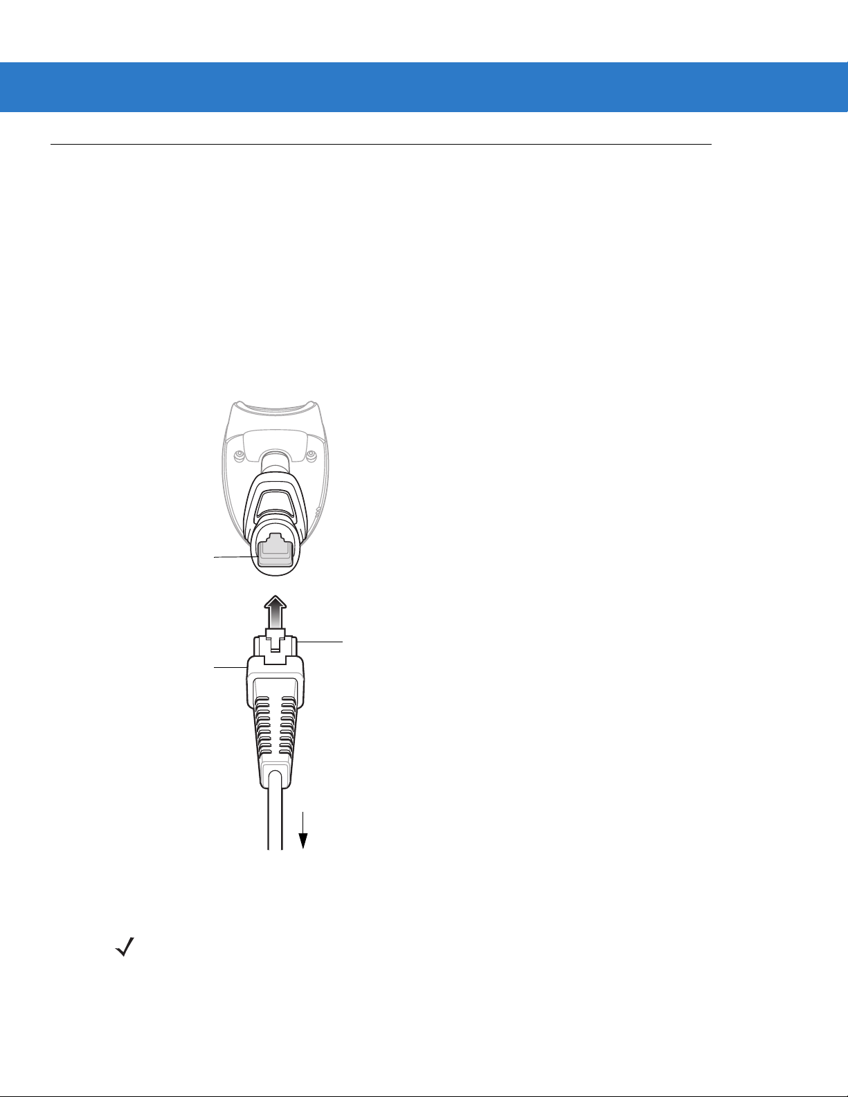
Setting Up the Scanner
Interface cable
modular connector
To host
Cable interface
port
Interface cable modular
connector clip
Installing the Interface Cable
To con ne ct th e inte r fac e ca ble :
1. Insert the interface cable’s modular connector clip into the cable interface port on the bottom of the scanner
handle. (See Figure 1-2.).
2. Gently tug the cable to ensure the connector is properly secured.
3. Connect the other end of the interface cable to the host. (See the specific host chapter for information on host
connections.)
Getting Started 1 - 3
Figure 1-2
Installing the Cable
NOTE Different hosts require different cables. The connectors illustrated in each host chapter are examples only.
Actual connectors may be different than those illustrated, but the steps to connect the scanner are the
same.
1 - 4 LS4208 Product Reference Guide
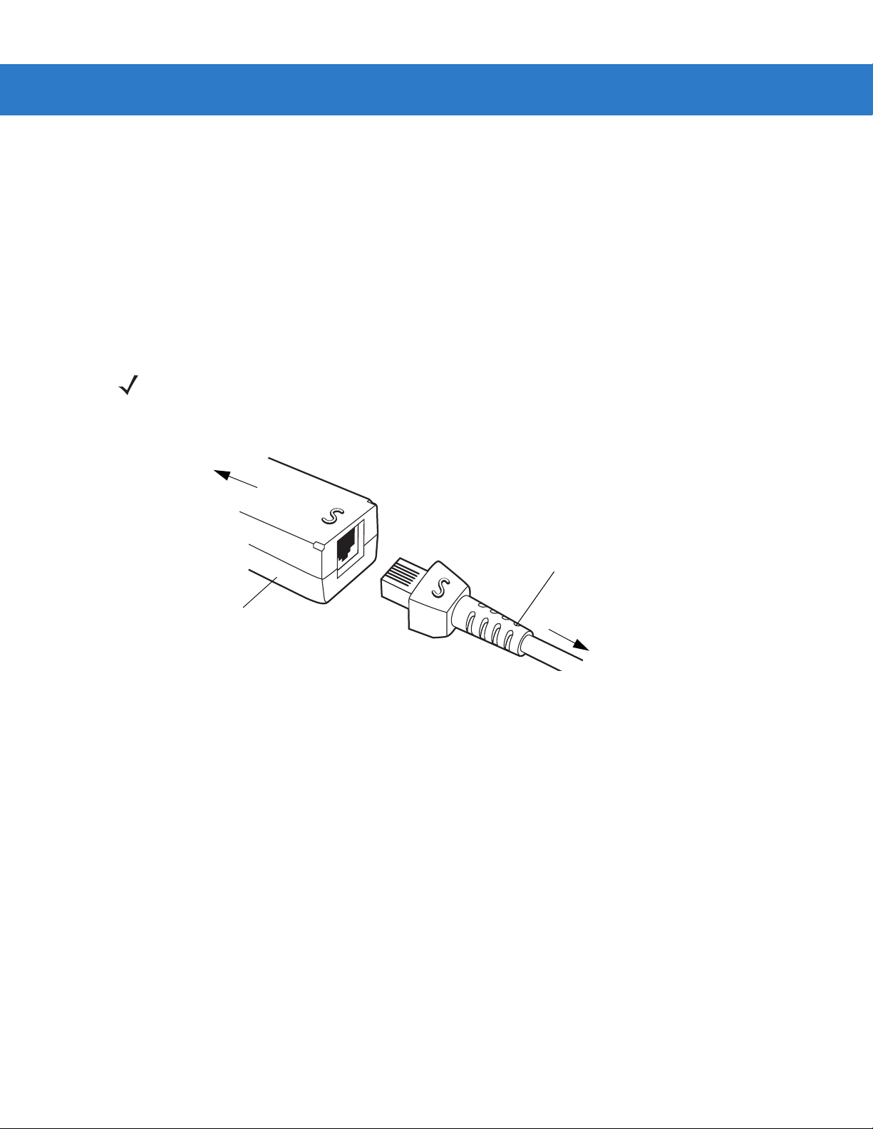
Synapse Adapter Cable
To Scanner
Synapse Smart Cable
To host
Removing the Interface Cable
To rem ov e th e inte r fa ce ca ble :
1. Unplug the installed cable’s modular connector by depressing the connector clip with the tip of a screwdriver.
2. Carefully slide out the cable.
3. Follow the steps for Installing the Interface Cable on page 1-3 to connect a new cable.
Connecting a Synapse Cable Interface
NOTE Refer to the Synapse Interface Guide provided with the Synapse cable for detailed setup instructions.
Symbol’s Synapse Smart Cables enable interfacin g to a variety of hosts. The appropriate Synapse cable has the
built-in intelligence to detect the host to which it is connected.
Figure 1-3
1. Plug the Synapse adapter cable (p/n 25-32463-xx) into the bottom of the scann er, as described in Installing the
2. Align the ‘S’ on the Synapse adapter cable with the ‘S’ on the Synapse Smart Cable and plug the cable in.
3. Connect the other end of the Synapse Smart Cable to the host.
Connecting Power (if required)
If the host does not provide power to the scanner, an external power connection to the scanner is required. To
connect power:
1. Connect the interface cable to the bottom of the scanner, as described in Installing the Interface Cable on page
2. Connect the other end of the interface cable to the host (refer to the host manual to locate the correct port).
3. Plug the power supply into the power jack on the interface cable. Plug the other end of the power supp ly into
Synapse Cable Connection
Interface Cable on page 1-3.
1-3.
an AC outlet.

Getting Started 1 - 5
Configuring the Scanner
To configure the scanner, use the bar codes included in this manual, or the 123Scan configuration program.
See Chapter 4, User Preferences, Chapter 12, Symbologies and Chapter 13, Miscellaneous Scanner Options for
information about programming the scanner using b ar code menus. Also see each ho st-specific chapter to set up a
connection to a specific host type.
See Chapter 11, 123Scan to configure the scanner using this configuration program. A help file is available in the
program.

1 - 6 LS4208 Product Reference Guide
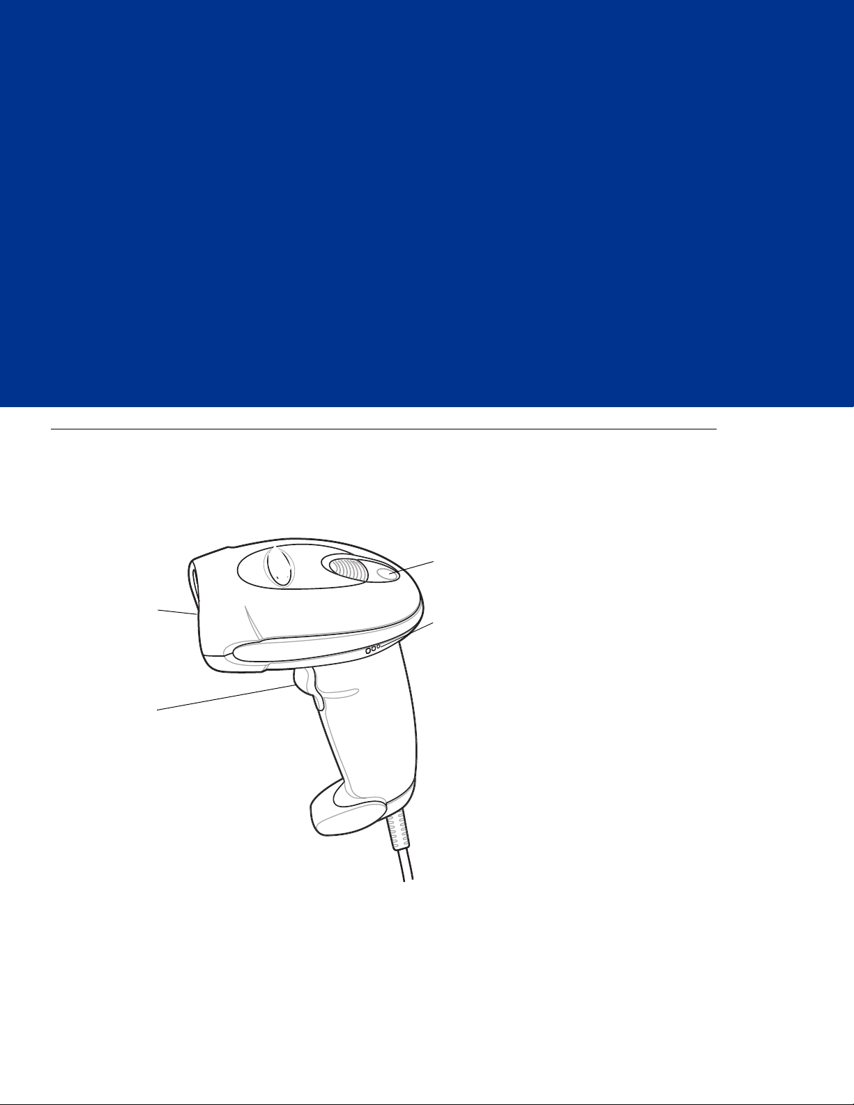
Chapter 2 Scanning
Beeper
LED
Trigger
Scan
Window
Introduction
This chapter provides beeper and LED definitions, techniqu es involved in scanning bar codes, general instructions
and tips about scanning, and decode zone diagram.
Figure 2-1
Parts

2 - 2 LS4208 Product Reference Guide
Beeper Definitions
The scanner issues different beep sequences and patterns to indicate status. Table 2-1 defines beep sequences
that occur during both normal scanning and while programming the scanner.
Table 2-1
Standard Use
Low/medium/high beeps Power up.
Short high beeps A bar code symbol was decoded (if decode beeper is
Clicking Occurs during PDF417 decoding to indicate proper
4 long low beeps A transmission error was detected in a scanned symbol.
5 low beeps Conversion or format error.
Low/high/low beeps Advanced Data Formatting (ADF) transmit error. See
High/high/high/low beeps RS-232 receive error.
Parameter Menu Scanning
Short high beeps Correct entry scanned or correct menu sequence
Beeper Definitions
Beeper Sequence Indication
enabled).
alignment, motion, and distance.
The data is ignored. This occurs if a unit is not properly
configured. Check option setting.
Chapter 14, Advanced Data Formatting
performed.
.
Low/high beeps Input error, incorrect bar code or “Cancel” scanned, wrong
entry, incorrect bar code programming sequence; remain in
program mode.
High/low beeps Keyboard parameter selected. Enter value using bar code
keypad.
High/low/high/low beeps Successful program exit with change in the parameter
setting.
Low/high/low/high beeps Out of host parameter storage space. Scan
Parameters on page 4-3
Code 39 Buffering
High/low beeps New Code 39 data was entered into the buffer.
3 Beeps - long high beeps Code 39 buffer is full.
Low/high/low beeps The Code 39 buffer was erased or there was an attempt to
clear or transmit an empty buffer.
Low/high beeps A successful transmission of buffered data.
.
Default

Scanning 2 - 3
Table 2-1
Host Specific
Beeper Definitions (Continued)
USB only
4 short high beeps Scanner has not completed initialization. Wait several
Scanner gives a power-up beep after
scanning a USB Device Type.
This power-up beep occurs more than once. The USB bus may put the scanner in a state where power to
RS-232 only
1 short high beep A <BEL> character is received and Beep on <BEL> is
LED Definitions
In addition to beeper sequences, the scanner communicates with the user using a two-color LED display. Table 2-2
defines LED colors that display during scanning.
Beeper Sequence Indication
seconds and scan again.
Communication with the bus must be established before the
scanner can operate at the highest power level.
the scanner is cycled on and off more than once. This is
normal and usually happens when the host cold boots.
enabled.
Table 2-2
Off No power is applied to the scanner, or the scanner is on and ready to scan.
Green A bar code was successfully decoded.
Red A data transmission error or scanner malfunction occurred.
Standard LED Definitions
LED Indication
2 - 4 LS4208 Product Reference Guide
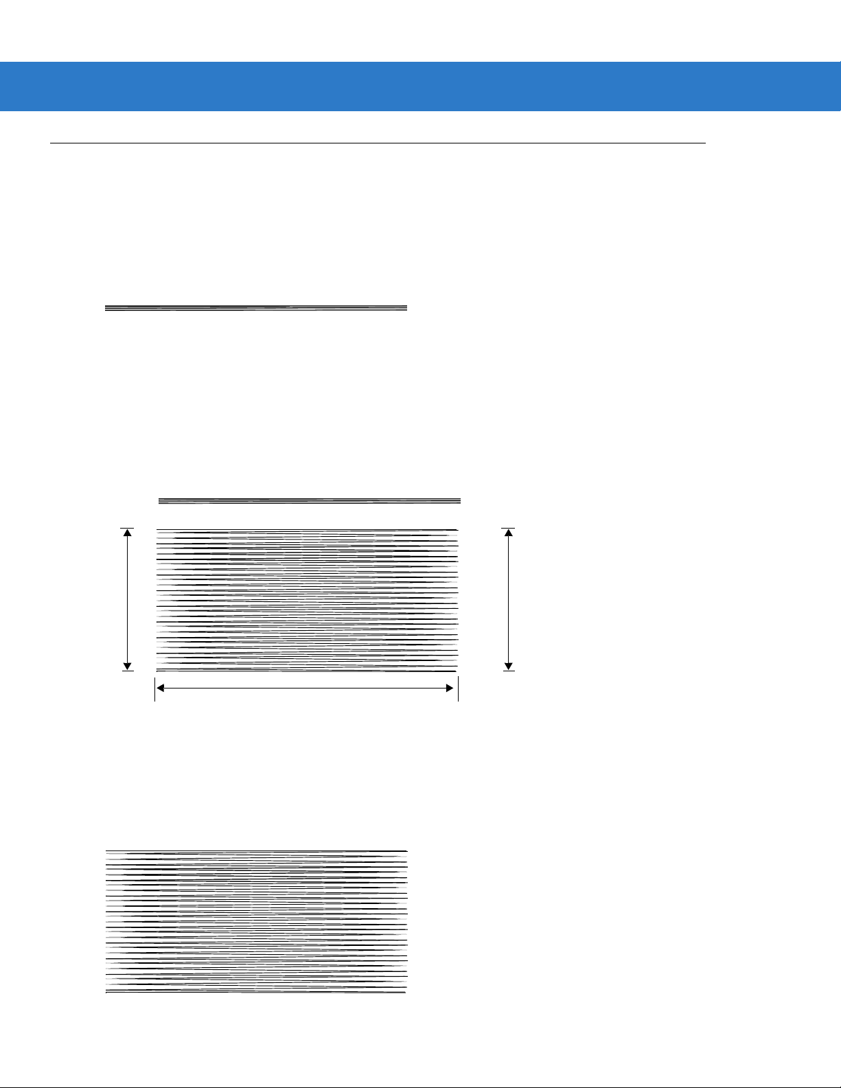
Single Scan Line Pattern
Open Raster Pattern
Y-Axis
Y-Axis
Horizontal Displacement (X - Axis)
Scan Patterns
The scanner emits several scanning patterns, described as follows. To select a pattern, see Scan Pattern on page
4-6.
Single-Line Only
The laser has no up and down scan line movement (no raster).
Figure 2-2
Single-Line Only Scan Pattern
Multi-Line Smart Raster
The scan line begins as a single line and moves up and down (rasters) when a partial scan of a bar code is
detected, or no bar code is decoded 500 ms after the trigger is pulled. If the scanner detects a PDF417
(LS4208-PR only), GS1 DataBar, or Composite Code, it immediately rasters, opening to a full, optimized raster
pattern as soon as the scanner is properly aligned over the bar code.
Figure 2-3
Multi-Line Smart Raster Scan Pattern
Multi-line Always Raster
Rastering (up and down scan line movement) begins immediately to decode 1D, PDF417 (LS4208-PR only), GS1
DataBar, and Composite Codes.
Figure 2-4
Multi-Line Always Raster Scan Pattern
Scanning Modes
Single-Line Mode
Multi-Line Raster Mode
The LS4208 accommodates both hand-held and hands-free modes. In hand-held use, you pull the trigger to
activate the scan pattern and decode the bar code. In hands-free mode, the scanner sits in the Intellistand and
automatically decodes a bar code presented in its field of view.
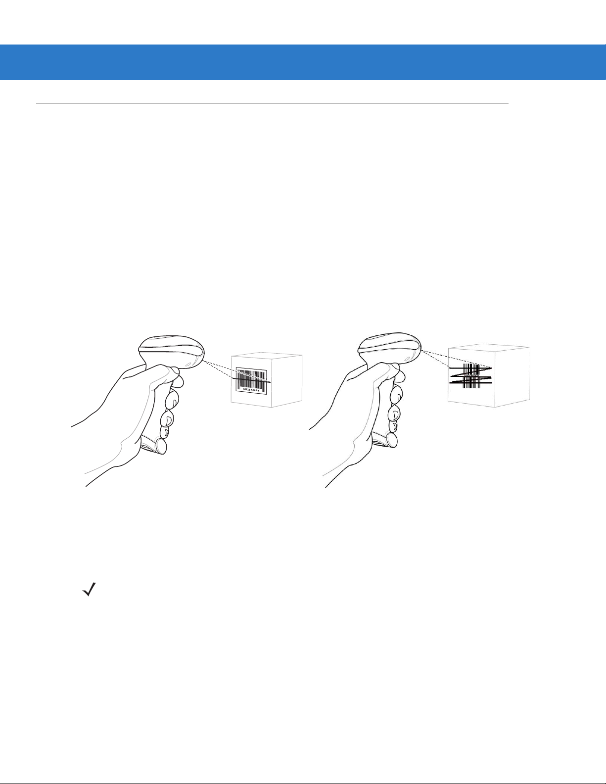
Scanning in Hand-Held Mode
Install and program the scanner (see Setting Up the Scanner on page 1-3). For assistance, contact Zebra Mobility
Support. See page xv for contact information.
To scan in hand-held mode:
1. Ensure all connections are secure. (See the host chapter for the scanner.)
2. Aim the scanner at the bar code.
3. Press the trigger.
Scanning 2 - 5
Figure 2-5
Upon successful decode, the scanner beeps and the LED turns green. For more informatio n about beeper and
LED definitions, see Table 2-1 and Table 2-2.
Scanning in Hand-Held Mode
NOTE Scan line lengths vary depending on the scan line width selected (see Scan Line Width on page 4-7). A full
scan line width is the default. Medium and short scan line widths are useful for scannin g me nu s or
pick-lists.
2 - 6 LS4208 Product Reference Guide
012345
012345
012345
012345
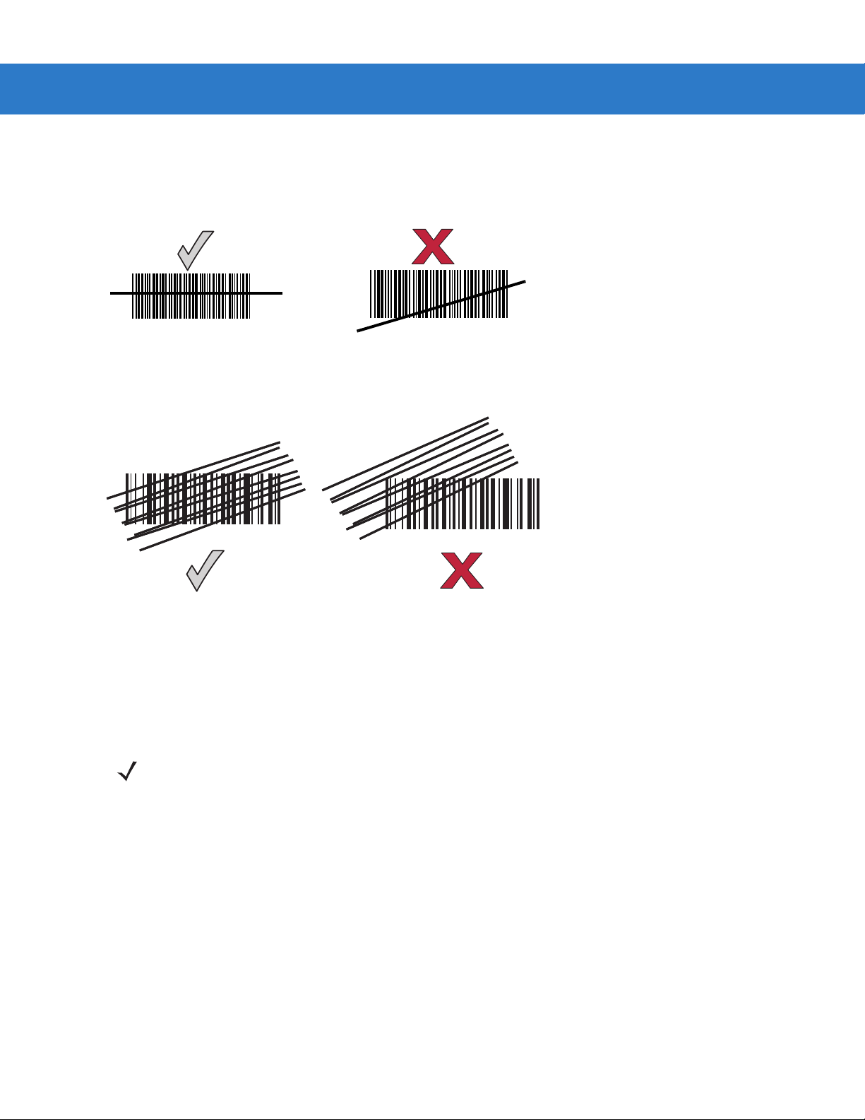
Aiming
On a typical UPC 100% hold the scanner between contact and 19 inches from the symbol (see Symbol LS4208
Decode Zone on page 2-11). When scanning using a single-line scan mode, ensure the scan line crosses every
bar and space of the symbol.
Figure 2-6
Acceptable and Incorrect Single-Line Aiming
When scanning using a multi-line raster mode, at least one scan line must cross every bar and space of the
symbol.
Figure 2-7
Acceptable and Incorrect Multi-Line Aiming
Regardless of the scan mode, the scan line is smaller when the scanner is closer to the symbol and larger when it
is farther from the symbol. Scan symbols with smaller bars or elements (mil size) clos er to the scanner, and those
with larger bars or elements (mil size) farther from the scanner.
Do not hold the scanner directly over the bar code. Laser light reflecting directly back into the scanner from the bar
code is known as specular reflection. This specular reflection can make decoding difficult.
NOTE Scan line lengths vary depending on the scan line width selected (see Scan Line Width on page 4-7). A full
scan line width is the default. Medium and short scan line widths are useful for scannin g me nu s or
pick-lists.
 Loading...