

Zebra LS3578 Product Reference Manual
LS3578
Product Reference Guide


LS3578
Product Reference Guide
72E-93911-05
Revision A
July 2016

ii LS3578 Product Reference Guide
© 2015 Symbol Technologies, Inc.
No part of this publication may be reproduced or used in any form, or by any electrical or mechanical means,
without permission in writing from Zebra. This includes electronic or mechanical means, such as photocopying,
recording, or information storage and retrieval systems. The material in this manual is subject to change
without notice.
The software is provided strictly on an “as is” basis. All software, including firmware, furnished to the user is on
a licensed basis. Zebra grants to the user a non-transferable and non-exclusive license to use each software
or firmware program delivered hereunder (licensed program). Except as noted below, such license may not be
assigned, sublicensed, or otherwise transferred by the user without prior written consent of Zebra. No right to
copy a licensed program in whole or in part is granted, except as permitted under copyright law. The user shall
not modify, merge, or incorporate any form or portion of a licensed program with other program material, create
a derivative work from a licensed program, or use a licensed program in a network without written permission
from Zebra. The user agrees to maintain Zebra’s copyright notice on the licensed programs delivered
hereunder, and to include the same on any authorized copies it makes, in whole or in part. The user agrees not
to decompile, disassemble, decode, or reverse engineer any licensed program delivered to the user or any
portion thereof.
Zebra reserves the right to make changes to any software or product to improve reliability, function, or design.
Zebra does not assume any product liability arising out of, or in connection with, the application or use of any
product, circuit, or application described herein.
No license is granted, either expressly or by implication, estoppel, or otherwise under any Zebra Technologies
Corporation, intellectual property rights. An implied license only exists for equipment, circuits, and subsystems
contained in Zebra products.
Zebra and the Zebra head graphic are registered trademarks of ZIH Corp. The Symbol logo is a registered
trademark of Symbol Technologies, Inc., a Zebra Technologies company.
Zebra Technologies Corporation
Lincolnshire, IL U.S.A.
http://www.zebra.com
Warranty
For the complete Zebra hardware product warranty statement, go to:
http://www.zebra.com/warranty

Revision History
Changes to the original manual are listed below:
Change Date Description
-01 Rev A 5/2007 Initial release.
-02 Rev A 4/2008 Remove HID Profile (Master) option, add Discoverable Mode parameter, update
-03 Rev A 11/2012 Update: URLs; ambient light tolerance; service information; Feedback page fax
-04 Rev A 10/2014 Zebra Branding
-04 Rev B 3/2015 Zebra Branding
iii
Auto-reconnect in Bluetooth Keyboard Emulation (HID Slave) Mode options, update
Pairing Mode information, add French Belgian country codes.
number
Remove: Patent statement; "Symbol" brand name; link to www.symbol.com/usb;
motion art from back cover.
-05 Rev A 7/2016 Update Advanced Data Formatting chapter.

iv LS3578 Product Reference Guide

Table of Contents
Warranty ........................................................................................................................ ii
Revision History............................................................................................................. iii
About This Guide
Introduction .................................................................................................................... xiii
Chapter Descriptions ..................................................................................................... xiii
Notational Conventions.................................................................................................. xiv
Related Documents ....................................................................................................... xv
Service Information........................................................................................................ xv
Chapter 1: Getting Started
Introduction ................................................................................................................... 1-1
Unpacking the Scanner ................................................................................................ 1-2
The Cradle .................................................................................................................... 1-2
Cradle Parts ............................................................................................................ 1-3
Connecting the Cradle ............................................................................................ 1-4
Supplying Power to the Cradle ............................................................................... 1-6
Connecting a Synapse Cable Interface .................................................................. 1-6
Mounting the Cradle ................................................................................................ 1-6
Inserting the Battery ...................................................................................................... 1-7
Removing the Battery ............................................................................................. 1-8
Charging the Scanner Battery in the Cradle ................................................................. 1-8
Scanner Charging LED ........................................................................................... 1-8
Inserting the Scanner in the Cradle .............................................................................. 1-9
Sending Data to the Host Computer ............................................................................. 1-10
Pairing ..................................................................................................................... 1-10
Lost Connection to Host .......................................................................................... 1-10
Configuring the Scanner ............................................................................................... 1-10
Radio Communications ................................................................................................. 1-10

vi LS3578 Product Reference Guide
Chapter 2: Scanning
Introduction ................................................................................................................... 2-1
Beeper Definitions ........................................................................................................ 2-1
LED Definitions ............................................................................................................. 2-4
Scanning ....................................................................................................................... 2-5
Aiming ..................................................................................................................... 2-6
Decode Zone ................................................................................................................ 2-7
Chapter 3: Maintenance and Technical Specifications
Introduction ................................................................................................................... 3-1
Maintenance ................................................................................................................. 3-1
Battery Maintenance ............................................................................................... 3-1
Troubleshooting ............................................................................................................ 3-2
Technical Specifications ............................................................................................... 3-5
Scanner Signal Descriptions ......................................................................................... 3-7
Chapter 4: Radio Communications
Introduction ................................................................................................................... 4-1
Scanning Sequence Examples ............................................................................... 4-1
Errors While Scanning ............................................................................................ 4-1
Radio Communications Parameter Defaults ................................................................. 4-2
Wireless Beeper Definitions .......................................................................................... 4-3
Radio Communications Host Types ............................................................................. 4-4
Bluetooth Technology Profile Support .......................................................................... 4-6
Master/Slave Set Up ............................................................................................... 4-6
Bluetooth Friendly Name ........................................................................................ 4-7
Discoverable Mode ................................................................................................. 4-7
HID Host Parameters .................................................................................................... 4-8
HID Country Keyboard Types (Country Codes) ...................................................... 4-9
HID Keyboard Keystroke Delay .............................................................................. 4-11
HID CAPS Lock Override ........................................................................................ 4-11
HID Ignore Unknown Characters ............................................................................ 4-12
Emulate Keypad ...................................................................................................... 4-12
HID Keyboard FN1 Substitution .............................................................................. 4-13
HID Function Key Mapping ..................................................................................... 4-13
Simulated Caps Lock .............................................................................................. 4-14
Convert Case .......................................................................................................... 4-14
Auto-reconnect Feature ................................................................................................ 4-15
Reconnect Attempt Beep Feedback ....................................................................... 4-15
Reconnect Attempt Interval ..................................................................................... 4-16
Auto-reconnect in Bluetooth Keyboard Emulation (HID Slave) Mode ..................... 4-18
Out of Range Indicator .................................................................................................. 4-19
Scanner(s) To Cradle Support ...................................................................................... 4-20
Modes of Operation ................................................................................................ 4-20
Parameter Broadcast (Cradle Host Only) ............................................................... 4-21
Pairing ..................................................................................................................... 4-21
Pairing Bar Code Format ........................................................................................ 4-24
Connection Maintenance Interval ........................................................................... 4-24

Table of Contents vii
Bluetooth Security ......................................................................................................... 4-27
Authentication ......................................................................................................... 4-27
PIN Code ................................................................................................................. 4-28
Encryption ............................................................................................................... 4-29
Chapter 5: User Preferences
Introduction ................................................................................................................... 5-1
Scanning Sequence Examples ..................................................................................... 5-2
Errors While Scanning .................................................................................................. 5-2
User Preferences Default Parameters .......................................................................... 5-2
User Preferences .......................................................................................................... 5-4
Default Parameters ................................................................................................. 5-4
Beeper Tone ........................................................................................................... 5-5
Beeper Volume ....................................................................................................... 5-6
Laser On Time ........................................................................................................ 5-7
Beep After Good Decode ........................................................................................ 5-7
Trigger Mode ........................................................................................................... 5-8
Aim Duration ........................................................................................................... 5-9
Beep on Insertion .................................................................................................... 5-9
Time Delay to Reduced Power Mode ..................................................................... 5-10
Transmit Code ID Character ................................................................................... 5-11
Scan Angle .............................................................................................................. 5-11
Prefix/Suffix Values ................................................................................................. 5-12
Scan Data Transmission Format ............................................................................. 5-13
FN1 Substitution Values .......................................................................................... 5-15
Transmit “No Read” Message ................................................................................. 5-15
Synapse Interface ................................................................................................... 5-16
Batch Mode ............................................................................................................. 5-17
Report Scanner Version ................................................................................................ 5-19
Report Scan Engine Version ......................................................................................... 5-19
Report MIMIC Version .................................................................................................. 5-19
Report Synapse Cable .................................................................................................. 5-19
Chapter 6: Keyboard Wedge Interface
Introduction ................................................................................................................... 6-1
Connecting a Keyboard Wedge Interface ..................................................................... 6-2
Keyboard Wedge Default Parameters .......................................................................... 6-3
Keyboard Wedge Host Types ....................................................................................... 6-4
Keyboard Wedge Host Types ................................................................................. 6-4
Keyboard Wedge Country Types (Country Codes) ................................................. 6-5
Ignore Unknown Characters ................................................................................... 6-7
Keystroke Delay ...................................................................................................... 6-7
Intra-Keystroke Delay .............................................................................................. 6-8
Alternate Numeric Keypad Emulation ..................................................................... 6-8
Caps Lock On ......................................................................................................... 6-9
Caps Lock Override ................................................................................................ 6-9
Convert Wedge Data ............................................................................................... 6-10
Function Key Mapping ............................................................................................ 6-10

viii LS3578 Product Reference Guide
FN1 Substitution ..................................................................................................... 6-11
Send Make and Break ............................................................................................ 6-11
Keyboard Maps ............................................................................................................. 6-12
ASCII Character Set ..................................................................................................... 6-14
Chapter 7: RS-232 Interface
Introduction ................................................................................................................... 7-1
Connecting an RS-232 Interface .................................................................................. 7-2
RS-232 Default Parameters .......................................................................................... 7-3
RS-232 Host Parameters .............................................................................................. 7-4
RS-232 Host Types ................................................................................................. 7-6
Baud Rate ............................................................................................................... 7-7
Parity ....................................................................................................................... 7-9
Check Receive Errors ............................................................................................. 7-10
Stop Bit Select ........................................................................................................ 7-11
Data Bits ................................................................................................................. 7-11
Hardware Handshaking .......................................................................................... 7-12
Software Handshaking ............................................................................................ 7-14
Host Serial Response Time-out .............................................................................. 7-16
RTS Line State ........................................................................................................ 7-17
Beep on <BEL> ....................................................................................................... 7-17
Intercharacter Delay ................................................................................................ 7-18
Nixdorf Mode A/B and OPOS/JPOS Beep/LED Options ........................................ 7-19
Ignore Unknown Characters ................................................................................... 7-20
ASCII / Character Set ................................................................................................... 7-20
Chapter 8: USB Interface
Introduction ................................................................................................................... 8-1
Connecting a USB Interface ......................................................................................... 8-2
USB Default Parameters .............................................................................................. 8-4
USB Host Parameters .................................................................................................. 8-5
USB Device Type .................................................................................................... 8-5
USB Country Keyboard Types (Country Codes) .................................................... 8-6
USB Keystroke Delay ............................................................................................. 8-8
USB Caps Lock Override ........................................................................................ 8-9
USB Ignore Unknown Characters ........................................................................... 8-9
Emulate Keypad ...................................................................................................... 8-10
USB Keyboard FN 1 Substitution ............................................................................ 8-10
Function Key Mapping ............................................................................................ 8-11
Simulated Caps Lock .............................................................................................. 8-11
Convert Case .......................................................................................................... 8-12
ASCII Character Set ..................................................................................................... 8-13
Chapter 9: IBM 468X/469X Interface
Introduction ................................................................................................................... 9-1
Connecting to an IBM 468X/469X Host ........................................................................ 9-2
IBM Default Parameters ............................................................................................... 9-3

Table of Contents ix
IBM 468X/469X Host Parameters ................................................................................. 9-4
Port Address ........................................................................................................... 9-4
Convert Unknown to Code 39 ................................................................................. 9-4
Chapter 10: 123Scan
Introduction ................................................................................................................... 10-1
Setting Up 123Scan ...................................................................................................... 10-1
Chapter 11: Symbologies
Introduction ................................................................................................................... 11-1
Scanning Sequence Examples ..................................................................................... 11-1
Errors While Scanning .................................................................................................. 11-1
Symbology Default Parameters .................................................................................... 11-2
UPC/EAN ...................................................................................................................... 11-5
Enable/Disable UPC-A ............................................................................................ 11-5
Enable/Disable UPC-E ............................................................................................ 11-5
Enable/Disable UPC-E1 .......................................................................................... 11-6
Enable/Disable EAN-13 .......................................................................................... 11-6
Enable/Disable EAN-8 ............................................................................................ 11-7
Enable/Disable Bookland EAN ................................................................................ 11-7
Decode UPC/EAN/JAN Supplementals .................................................................. 11-8
User-Programmable Supplementals ....................................................................... 11-11
UPC/EAN/JAN Supplemental Redundancy ............................................................ 11-12
Transmit UPC-A/UPC-E/UPC-E1 Check Digit ........................................................ 11-12
UPC-A Preamble ..................................................................................................... 11-14
UPC-E Preamble ..................................................................................................... 11-15
UPC-E1 Preamble ................................................................................................... 11-16
Convert UPC-E to UPC-A ....................................................................................... 11-17
Convert UPC-E1 to UPC-A ..................................................................................... 11-17
EAN-8/JAN-8 Extend .............................................................................................. 11-18
Bookland ISBN Format ........................................................................................... 11-19
UCC Coupon Extended Code ................................................................................. 11-20
Code 128 ...................................................................................................................... 11-21
Enable/Disable Code 128 ....................................................................................... 11-21
Enable/Disable UCC/EAN-128 ................................................................................ 11-22
Enable/Disable ISBT 128 ........................................................................................ 11-22
Code 39 ........................................................................................................................ 11-23
Enable/Disable Code 39 ......................................................................................... 11-23
Enable/Disable Trioptic Code 39 ............................................................................. 11-23
Convert Code 39 to Code 32 .................................................................................. 11-24
Code 32 Prefix ........................................................................................................ 11-24
Set Lengths for Code 39 ......................................................................................... 11-25
Code 39 Check Digit Verification ............................................................................ 11-26
Transmit Code 39 Check Digit ................................................................................ 11-26
Code 39 Full ASCII Conversion .............................................................................. 11-27
Code 93 ........................................................................................................................ 11-28
Enable/Disable Code 93 ......................................................................................... 11-28
Set Lengths for Code 93 ......................................................................................... 11-28

x LS3578 Product Reference Guide
Code 11 ........................................................................................................................ 11-30
Code 11 .................................................................................................................. 11-30
Set Lengths for Code 11 ......................................................................................... 11-31
Code 11 Check Digit Verification ............................................................................ 11-32
Transmit Code 11 Check Digits .............................................................................. 11-33
Interleaved 2 of 5 (I 2 of 5) ............................................................................................ 11-34
Enable/Disable Interleaved 2 of 5 ........................................................................... 11-34
Set Lengths for Interleaved 2 of 5 ........................................................................... 11-34
I 2 of 5 Check Digit Verification ............................................................................... 11-36
Transmit I 2 of 5 Check Digit ................................................................................... 11-36
Convert I 2 of 5 to EAN-13 ...................................................................................... 11-37
Discrete 2 of 5 (D 2 of 5) ............................................................................................... 11-37
Enable/Disable Discrete 2 of 5 ................................................................................ 11-37
Set Lengths for Discrete 2 of 5 ............................................................................... 11-38
Codabar (NW - 7) ......................................................................................................... 11-39
Enable/Disable Codabar ......................................................................................... 11-39
Set Lengths for Codabar ......................................................................................... 11-40
CLSI Editing ............................................................................................................ 11-41
NOTIS Editing ......................................................................................................... 11-41
MSI ............................................................................................................................... 11-42
Enable/Disable MSI ................................................................................................ 11-42
Set Lengths for MSI ................................................................................................ 11-43
MSI Check Digits .................................................................................................... 11-44
Transmit MSI Check Digit(s) ................................................................................... 11-45
MSI Check Digit Algorithm ...................................................................................... 11-45
GS1 DataBar ................................................................................................................ 11-46
GS1 DataBar-14 ..................................................................................................... 11-46
GS1 DataBar Limited .............................................................................................. 11-46
GS1 DataBar Expanded ......................................................................................... 11-47
Convert GS1 DataBar to UPC/EAN ........................................................................ 11-47
Redundancy Level ........................................................................................................ 11-48
Redundancy Level 1 ............................................................................................... 11-48
Redundancy Level 2 ............................................................................................... 11-48
Redundancy Level 3 ............................................................................................... 11-49
Redundancy Level 4 ............................................................................................... 11-49
Security Level ............................................................................................................... 11-50
Security Level 0 ...................................................................................................... 11-50
Security Level 1 ...................................................................................................... 11-50
Security Level 2 ...................................................................................................... 11-50
Security Level 3 ...................................................................................................... 11-51
Bi-directional Redundancy ............................................................................................ 11-51
Chapter 12: Advanced Data Formatting
Introduction ................................................................................................................... 12-1

Table of Contents xi
Appendix A: Standard Default Parameters
Appendix B: Programming Reference
Symbol Code Identifiers ................................................................................................ B-1
AIM Code Identifiers ..................................................................................................... B-2
Appendix C: Sample Bar Codes
UPC-A ........................................................................................................................... C-1
UPC-E ........................................................................................................................... C-1
UPC-E1 ......................................................................................................................... C-2
EAN-13 ......................................................................................................................... C-2
EAN-8 ........................................................................................................................... C-2
Code 39 ........................................................................................................................ C-2
Trioptic Code 39 ............................................................................................................ C-3
Code 93 ........................................................................................................................ C-3
Code 11 ........................................................................................................................ C-3
Codabar ........................................................................................................................ C-3
MSI ................................................................................................................................ C-4
Interleaved 2 of 5 .......................................................................................................... C-4
Appendix D: Numeric Bar Codes
0, 1, 2, 3 ........................................................................................................................ D-1
4, 5, 6, 7 ........................................................................................................................ D-2
8, 9 ................................................................................................................................ D-3
Cancel ........................................................................................................................... D-3
Appendix E: Alphanumeric Bar Codes
Alphanumeric Keyboard ................................................................................................ E-1
Glossary
Index
Tell Us What You Think...

xii LS3578 Product Reference Guide

About This Guide
Introduction
The LS3578 Product Reference Guide provides general instructions for setting up, operating, maintaining, and
troubleshooting the scanner. The LS3578 includes the following variations of the scanner:
•
LS3578-FZ: 1-D scanning
•
LS3578-ER: extended range 1-D scanning.
Chapter Descriptions
Topics covered in this guide are as follows:
•
Chapter 1, Getting Started provides a product overview and unpacking instructions.
•
Chapter 2, Scanning describes parts of the scanner, beeper and LED definitions, and how to use the
scanner.
•
Chapter 3, Maintenance and Technical Specifications provides information on how to care for the scanner,
troubleshooting, and technical specifications.
•
Chapter 4, Radio Communications provides information about the modes of operation and features available
for wireless communication between scanners, cradles and hosts, and also includes the parameters
necessary to configure the scanner.
•
Chapter 5, User Preferences describes each user preference feature and provides the programming bar
codes for selecting these features for the scanner. It also includes commonly used bar codes to customize
how data is transmitted to the host device.
•
Chapter 6, Keyboard Wedge Interface provides information for setting up the scanner for keyboard wedge
operation.
•
Chapter 7, RS-232 Interface provides information for setting up the scanner for RS-232 operation.
•
Chapter 8, USB Interface provides information for setting up the scanner for USB operation.
•
Chapter 9, IBM 468X/469X Interface provides information for setting up the scanner with IBM 468X/469X
POS systems.

xiv LS3578 Product Reference Guide
*Baud Rate 9600
Feature/Option
* Indicates Default
•
Chapter 10, 123Scan provides information on the PC-based scanner configuration tool 123Scan.
•
Chapter 11, Symbologies describes all symbology features and provides the programming bar codes for
selecting these features.
•
Chapter 12, Advanced Data Formatting (ADF) provides a reference to customize scanned data before
transmitting to the host.
•
Appendix A, Standard Default Parameters provides a table of all host devices and miscellaneous scanner
defaults.
•
Appendix B, Programming Reference provides a table of AIM code identifiers, ASCII character conversions,
and keyboard maps.
•
Appendix C, Sample Bar Codes includes sample bar codes.
•
Appendix D, Numeric Bar Codes includes the numeric bar codes to scan for parameters requiring specific
numeric values.
•
Appendix E, Alphanumeric Bar Co des includes the alphanumeric bar codes to scan for parameters requiring
alphanumeric values.
Notational Conventions
The following conventions are used in this document:
•
Italics are used to highlight the following:
• Chapters and sections in this and related documents
•
Bold text is used to highlight the following:
• Key names on a keypad
• Button names on a screen or window.
•
bullets (•) indicate:
• Action items
• Lists of alternatives
• Lists of required steps that are not necessarily sequential
•
Sequential lists (e.g., those that describe step-by-step procedures) appear as numbered lists.
•
Throughout the programming bar code menus, asterisks (*) are used to denote default parameter settings.
NOTE This symbol indicates something of special interest or importance to the reader. Failure to read the note
will not result in physical harm to the reader, equipment or data.

CAUTION This symbol indicates that if this information is ignored, the possiblity of data or material damage may
WARNING! This symbol indicates that if this information is ignored the possibility that serious personal
Related Documents
•
LS3578 Quick Start Guide (p/n 72-93587-xx) provides general information to help the user get started with
the scanner, including basic setup and operation instructions.
•
STB3508/3578 Cradle Quick Reference Guide (p/n 72-93912-xx) provides information on installing and
operating STB3508/3578 cradles.
•
FLB3508/3578 Cradle Quick Reference Guide (p/n 72-94604-xx) provides information on installing and
operating FLB3508/3578 cradles.
About This Guide xv
occur.
injury may occur.
For the latest version of this guide and all guides, go to:http://www.zebra.com/support
Service Information
If you have a problem using the equipment, contact your facility's technical or systems support. If there is a
problem with the equipment, they will contact the Zebra Global Customer Support Center at:
http://www.zebra.com/support.
When contacting Zebra support, please have the following information available:
•
Serial number of the unit
•
Model number or product name
•
Software type and version number
Zebra responds to calls by e-mail, telephone or fax within the time limits set forth in service agreements. If your
problem cannot be solved by Zebra support, you may need to return your equipment for servicing and will be given
specific directions. Zebra is not responsible for any damages incurred during shipment if the approved shipping
container is not used. Shipping the units improperly can possibly void the warranty.
If you purchased your business product from a Zebra business partner, please contact that business partner for
support.

xvi LS3578 Product Reference Guide

Chapter 1 Getting Started
Scan Trigger
Scan Window
LED
Indicators
Tether Plate
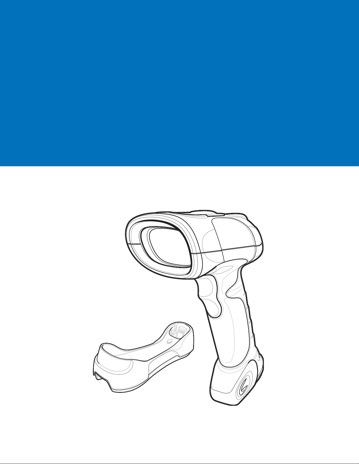
Introduction
The LS3578 scanner combines excellent scanning performance and advanced ergonomics to provide the best
value in a lightweight laser scanner, ensuring comfort and ease of use for extended periods of time.
Figure 1-1
LS3578 Scanner

1 - 2 LS3578 Product Reference Guide
This scanner supports the following host interfaces through communication with a cradle:
•
Standard RS-232 connection to a host.
•
Keyboard wedge connection to a host, where scanned data is interpreted as keystrokes. The following
international keyboards are supported (for Windows™ environment): North American, German, French,
French Canadian, Spanish, Italian, Swedish, UK English, Japanese, and Brazilian-Portuguese.
•
IBM® 468X/469X hosts.
•
USB connection to a host. The scanner autodetects a USB host and defaults to the HID keyboard interface
type. Select other USB interface types by scanning programming bar codes. The following international
keyboards are supported (for Windows™ environment): North America, German, French, French Canadian,
Spanish, Italian, Swedish, UK English, Japanese, and Brazilian-Portuguese.
•
Synapse capability, which allows connection to a wide variety of host systems using a Synapse cable and
Synapse adapter cable. The scanner autodetects the Synapse interface.
•
Configuration via 123Scan.
Unpacking the Scanner
Remove the scanner from its packing and inspect it for damage. If the scanner was damaged in transit, contact the
Zebra Global Customer Support Center. See page xv for contact information. KEEP THE PACKING. It is the
approved shipping container and should be used if the equipment ever needs to be returned for servicing.
The Cradle
The cradles serve as a stand and charger for the LS3578 cordless scanner. Some models also provide a host
communication interface. There are four versions of the cradle:
•
The STB3508 cordless cradle sits on a desktop or mounts on a wall, and charges the LS3578 cordless
scanner. An external power supply or a powered host cable charges the scanner.
•
The STB3578 cordless cradle sits on a desktop or mounts on a wall, and charges the LS3578 cordless
scanner This cradle also provides host communication by receiving scanner data via a Bluetooth radio, and
sending that data to the host through an attached cable. An external power supply or a powered host cable
charges the scanner.
•
The FLB3508 cordless cradle charges the LS3578 cordless scanner. The cradle attaches to a mounting
bracket using three isolators, and the bracket then mounts on the forklift surface. A portable power supply on
the forklift provides power to the cradle.
•
The FLB3578 cordless cradle charges the LS3578 cordless scanner, and provides host communication by
receiving scanner data via a Bluetooth radio, and sending that data to the host through an attached cable.
The cradle attaches to a mounting bracket using three isolators, and the bracket then mounts on the forklift
surface. A portable power supply on the forklift provides power to the cradle.
DO NOT use these cradles with a LS3478 scanner. Likewise, DO NOT use cradles designed for the LS3478 to
charge or provide communication for a LS3578 scanner.
NOTE For more information about communication between the scanner, cradle, and host, see Chapter 4, Radio
Communications.
For more information about mounting options and procedures, refer to the documentation included with the cradle.
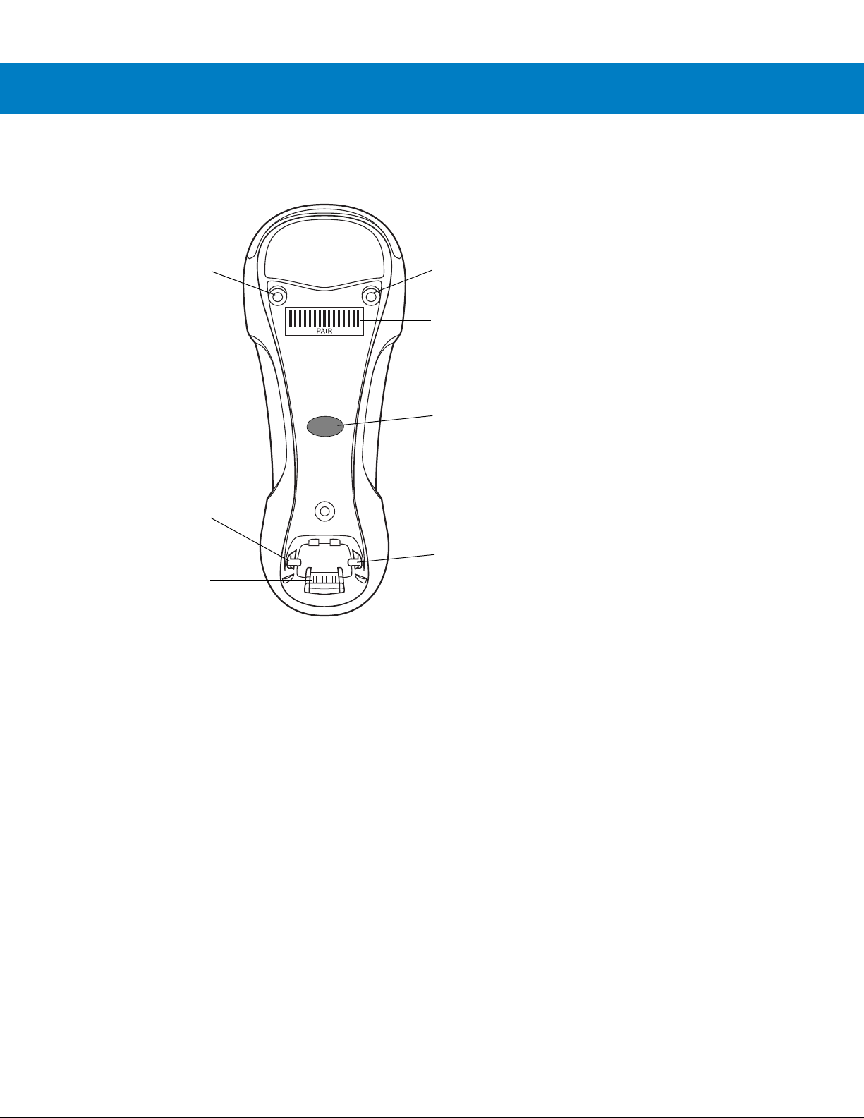
Cradle Parts
Mounting
Screw Hole
Mounting
Screw Hole
Pairing
Bar Code
Mounting
Screw Hole
Latch
Latch
Charging/
Communications
Contacts
LED
Getting Started 1 - 3
Figure 1-2
Cradle Front View
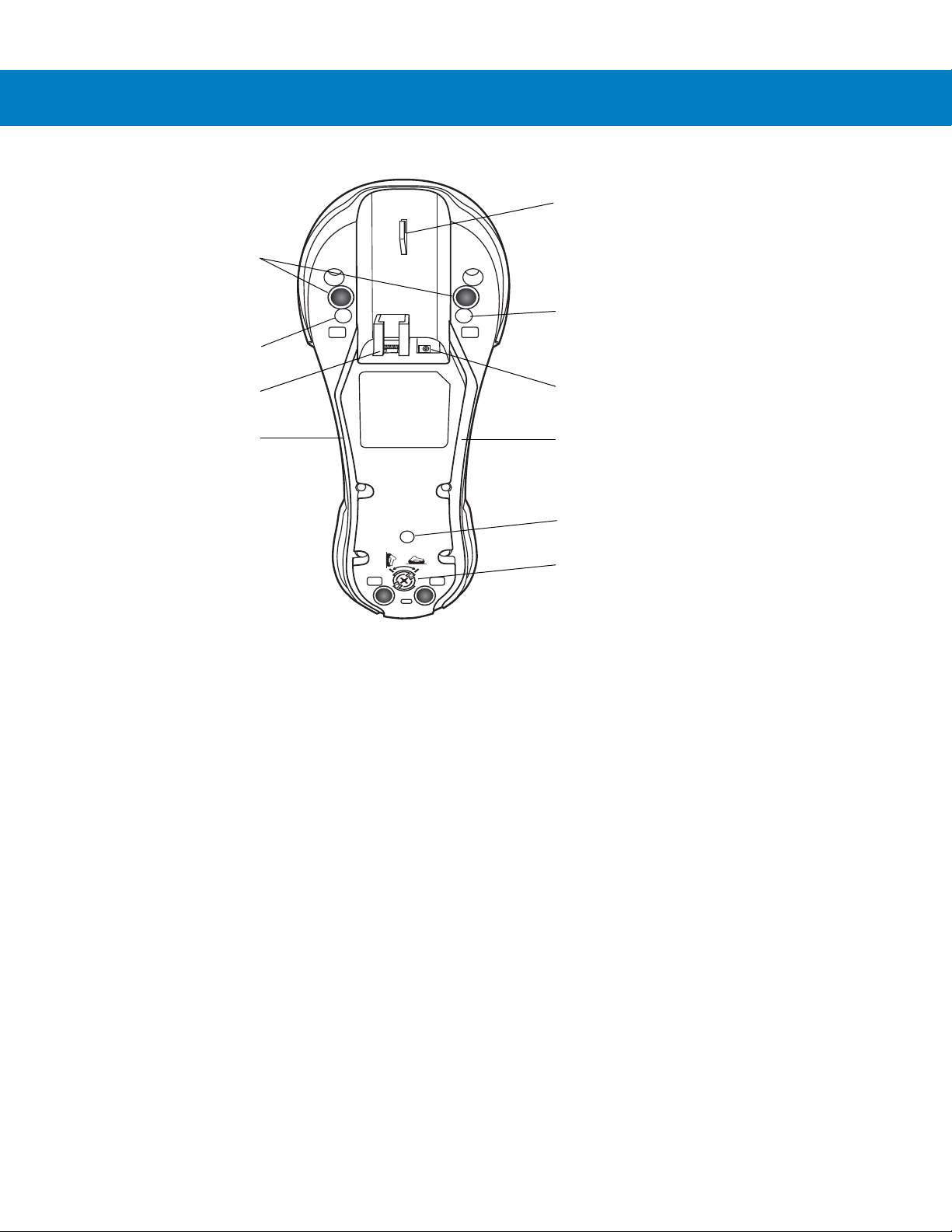
1 - 4 LS3578 Product Reference Guide
Rubber Feet
(STB3508/3578 Only)
Mounting Screw Hole
Mounting Screw Hole
Power Cable Groove
Power Port
Host Port
Host Cable Groove
Mounting Screw Hole
Converter Knob
Cable Hook
Figure 1-3
Connecting the Cradle
Important: Connect the interface cable and power supply (if necessary) in the following order to ensure proper operation of the
scanner and cradle.
Connecting STB3508/3578 Cradle
1. Insert the interface cable into the cradle's host port. See Figure 1-4.
2. Connect the other end of the interface cable to the host.
3. If necessary, connect the power supply to the cradle's power port (if the interface requires, or to allow fast
4. Connect the appropriate cable to the power supply and an AC power source, if necessary.
5. If applicable, thread the interface cable over the cable support hook and run the host and power cables into
6. Pair the scanner to the cradle by scanning the pairing bar code on the cradle.
7. If necessary, scan the appropriate host bar code (for non-autodetected interfaces). See the specific host
Cradle Back View
charging of the scanner).
their respective cable grooves.
chapter.
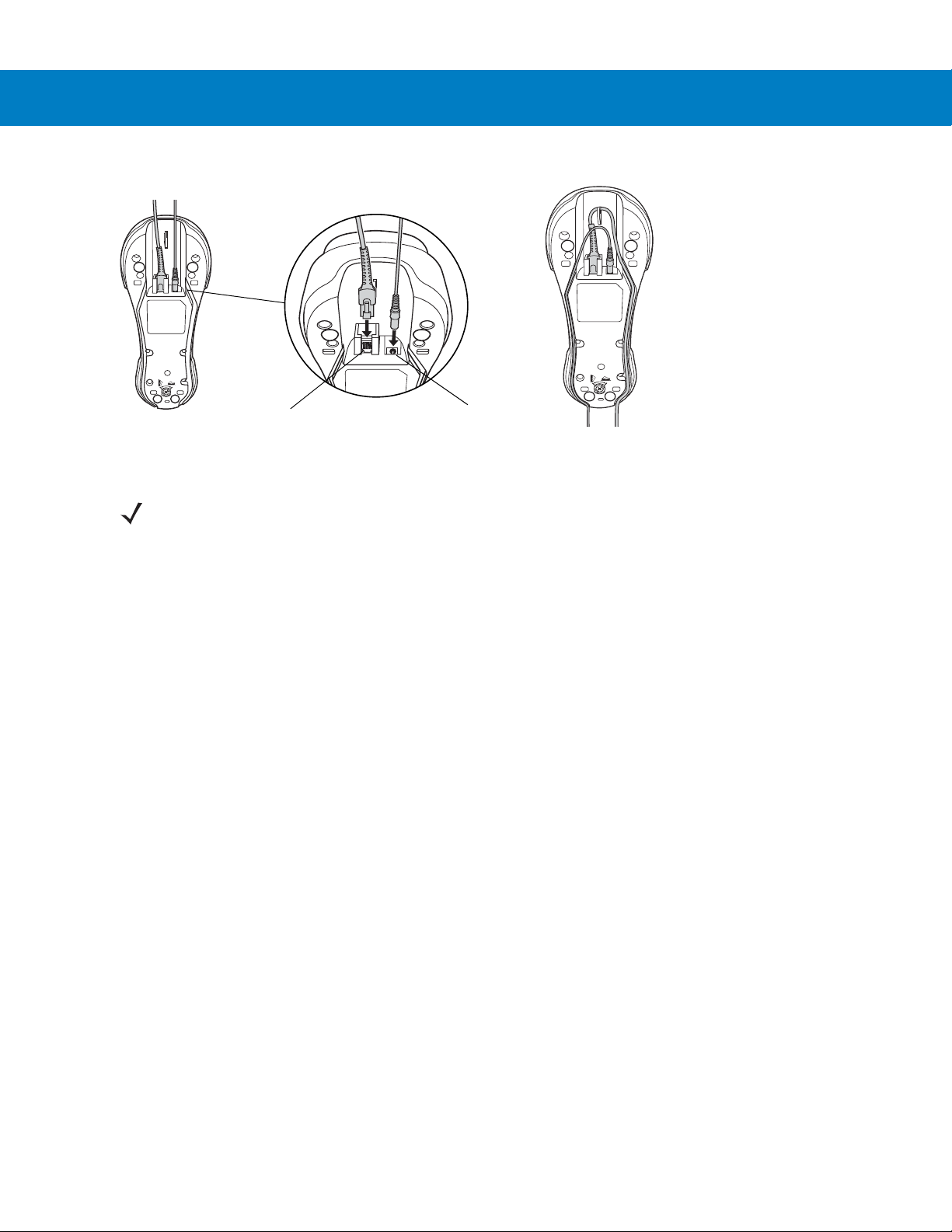
Getting Started 1 - 5
Host Port
Power Port
Figure 1-4
Connecting the Cables to the Cradle
NOTE Disconnect the power supply before changing host cables, or the scanner may not recognize the new
host.
Different cables are required for different hosts. The connectors illustrated in each host chapter are
examples only. The connectors may be different from those illustrated, but the steps to connect the
scanner remain the same
Connecting FLB3508/3578 Cradle
1. Insert the interface cable from the host computer into the cradle's host port. See Figure 1-4.
2. Connect the forklift power supply to the cradle's power port, if applicable.
3. Optionally, thread the host cable over the cable hook and run the host and power cables into their respective
cable grooves, or use cable ties to secure them to the mounting plate after attaching it to the cradle. For more
information about mounting options and procedures, refer to the documentation included with the cradle.
4. Pair the scanner with the cradle by scanning the pairing bar code on the cradle.
5. If necessary, scan the appropriate host bar code (for non-autodetected interfaces). See the specific host
chapter.
Changing the Host Interface
To connect to a different host, or to the same host using a different cable:
1. Disconnect the power supply from the cradle, if used.
2. Disconnect the interface cable from the host.
3. Connect the interface cable to the new host, or the new interface cable to the existing host.
4. Reconnect the power supply, if required.
5. If necessary, scan the appropriate host bar code (for non-autodetected interfaces). See the specific host
chapter.
1 - 6 LS3578 Product Reference Guide
Synapse adapter cable
To cradle
Synapse Smart Cable
To h o st
CAUTION If the scanner does not recognize the host, disconnect the power supply, then reconnect after
connecting the host cable.
Supplying Power to the Cradle
The cradle receives power from one of two sources:
•
An external power supply.
•
When connected to the host through an interface cable that supplies power.
The cradle detects whether the host or the external supply is supplying power. It always draws power from the
external supply when available, regardless of the presence of power from a host.
Using the USB Interface to Supply Power
When the cradle is connected to the host via the USB interface, the USB port can power the cradle so that an
external power supply is not necessary. Note that powering from a USB host charges the scanner at a slower rate
than when charging from an external power supply.
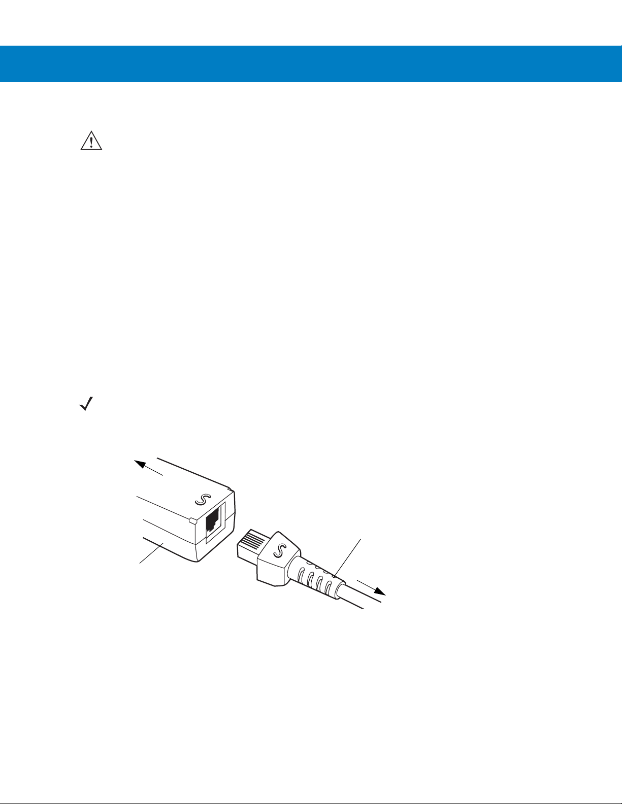
Connecting a Synapse Cable Interface
NOTE Refer to the Synapse Interface Guide provided with the Synapse cable for more information.
Zebra’s Synapse Smart Cables enable interfacing to a variety of hosts. The appropriate Synapse cable detects the
host.
Figure 1-5
1. Insert the Synapse adapter cable into the bottom of the cradle, as described in Connecting the Cables to the
Cradle on page 1-5.
Synapse Cable Connection
2. Align the ‘S’ on the Synapse adapter cable with the ‘S’ on the Synapse Smart Cable and plug the cable in.
3. Connect the other end of the Synapse Smart Cable to the host.
Mounting the Cradle
For information on mounting the cradle, refer to the documentation included with the cradle.
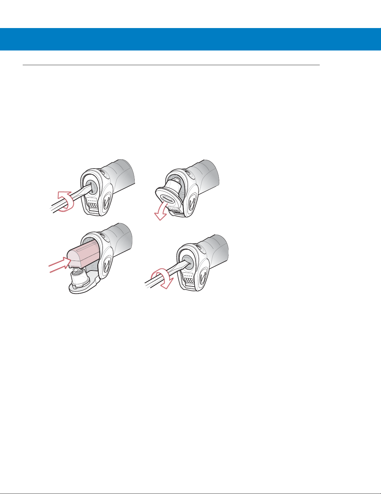
Inserting the Battery
The battery resides in a chamber in the scanner handle. To insert the battery:
1. Insert a coin or flathead screwdriver in the slot at the base of the scanner, then turn the slot counterclockwise
to release the latch.
2. Lift the latch.
3. If a battery is already installed, turn the scanner upright to slide the battery out.
4. Slide the new battery into the chamber, with the rounded side toward the back and the contacts facing into the
chamber.
Getting Started 1 - 7
Figure 1-6
5. Close the latch.
6. Insert a coin or flathead screwdriver in the slot at the base of the scanner, press down gently, and turn the slot
clockwise to lock the latch in place.
Inserting the Battery

1 - 8 LS3578 Product Reference Guide
Removing the Battery
To remove the battery:
1. Insert a coin or flathead screwdriver in the slot at the base of the scanner, then turn the slot counterclockwise
to release the latch.
2. Lift the latch.
3. Turn the scanner upright to slide the battery out.
Charging the Scanner Battery in the Cradle
For best performance, fully charge the scanner battery before using the scanner for the first time. To charge the
scanner battery, place the scanner in the cradle (see Inserting the Scanner in the Cradle on page 1-9). The battery
begins charging when the scanner LED indicator starts flashing green. A complete charge of a fully discharged
battery can take up to four hours using external power and up to 10 hours using the interface cable.
Charge within the recommended temperature of 32° to 104° F (0° to 40° C) nominal, 41° to 95° F (5° to 35° C)
ideal.
For information on maximizing battery life, see Battery Maintenance on page 3-1.
Scanner Charging LED
The scanner’s green LED indicates charging activity (see Table 2-2 on page 2-4). If the scanner is charging in fast
mode (non-bus powered mode), the green LED blinks at a fast rate. If the scanner is charging in slow mode
(bus-powered mode), the LED blinks at a slow rate.
If the scanner’s red LED begins flashing, indicating a charging problem, remove the scanner from the cradle and
replace the battery. If the red LED continues flashing, contact the Zebra Global Customer Support Center.
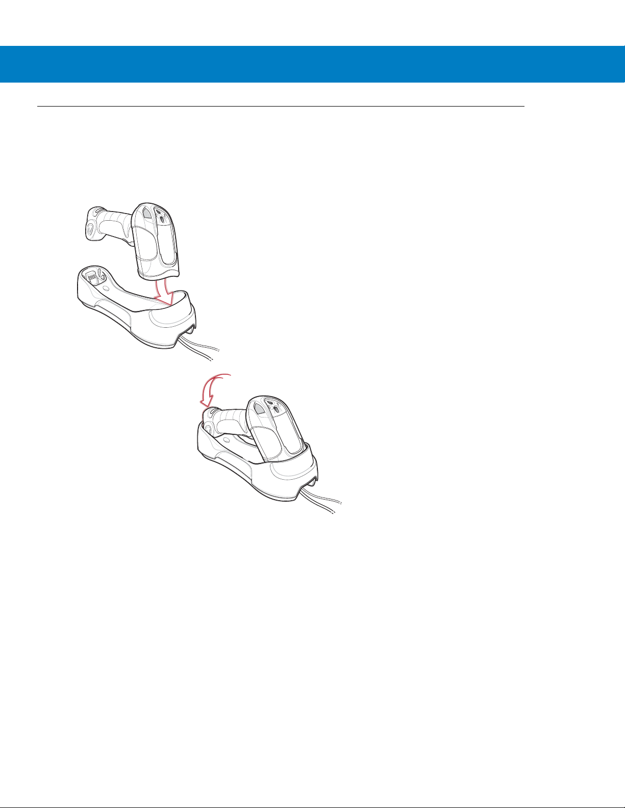
Inserting the Scanner in the Cradle
To insert the scanner in the cradle:
1. Insert the scanner into the cradle top first.
2. Push the handle until it clicks into place, engaging the contacts in the cradle and scanner.
Getting Started 1 - 9
Figure 1-7
Inserting the Scanner in the Cradle

1 - 10 LS3578 Product Reference Guide
Sending Data to the Host Computer
The cradle receives data from the scanner via a wireless radio connection and transmits it to the host computer via
the host cable. The scanner and cradle must be paired for successful wireless communication.
Pairing
Pairing registers a scanner to the cradle such that the scanner and cradle can exchange information. The
STB3578 and FLB3578 operate in two modes: Point-to-Point and Multipoint-to-Point. In Point-to-Point mode, pair
the scanner to the cradle either by inserting it in the cradle (if pairing on insertion is enabled), or by scanning the
pairing bar code. In Multipoint-to-Point mode, you can pair up to three scanners to one cradle. To use this feature,
scan the multipoint bar code in Multipoint-to-Point Communication on page 4-20.
The cradle includes pairing bar codes on both its front and back. To pair the scanner with the cradle, scan a pairing
bar code. A high-low-high-low beep sequence followed by a low-high beep sequence indicates successful pairing
and connection to the remote device. A long low, long high beep sequence indicates unsuccessful pairing.
NOTE The pairing bar code that connects the scanner to a cradle is unique to each cradle.
Do not scan data or parameters until pairing completes.
Lost Connection to Host
If scanned data does not transmit to the cradle's host, ensure that all cables are firmly inserted and the power
supply is connected to an appropriate AC outlet, if applicable. If scanned data still does not transmit to the host,
reestablish a connection with the host:
1. Disconnect the power supply from the cradle.
2. Disconnect the host interface cable from the cradle.
3. Wait three seconds.
4. Reconnect the host interface cable to the cradle.
5. Reconnect the power supply to the cradle, if the host requires.
6. Reestablish pairing with the cradle by scanning the pairing bar code.
Configuring the Scanner
Use the bar codes in this manual or the 123Scan
User Preferences and each host chapter for information about programming the scanner using bar code menus.
See Chapter 10, 123Scan to configure the scanner using this configuration program. 123Scan includes a help file.
configuration program to configure the scanner. See Chapter 5,
Radio Communications
The scanner can communicate with remote devices via Bluetooth Technology Profile Support, or by pairing with a
cradle. For radio communication parameters, detailed information about operational modes, Bluetooth Technology
Profile Support and pairing, see Chapter 4, Radio Communications.

Chapter 2 Scanning
Introduction
This chapter provides beeper and LED definitions, scanning techniques, general scanning instructions and tips,
and decode zone diagrams.
Beeper Definitions
The scanner emits different beeper sequences and patterns to indicate its status. Table 2-1 defines beep
sequences that occur during both normal scanning and while programming the scanner.
Table 2-1
Standard Use
Short low-short medium-short high beeps Power up.
One short high beep A bar code symbol was decoded (if decode beeper is enabled).
Four long low beeps A communication error occurred while transmitting a scanned
Low beep The scanner detects power when inserted into a cradle.
Low-high-low-high beeps Out of memory - the scanner cannot store the new bar code data.
Four short high beeps Low battery indication.
Five long low beeps Conversion or format error.
Wireless Operation
Short low-high beeps Scanner has paired with the cradle.
Standard Beeper Definitions
Beeper Sequence Indication
symbol to a host. The data is ignored. This occurs if the scanner is
not properly configured or if the scanner has disconnected from
the cradle.
Note: This feature can be disabled.
The scanner was inserted in an incompatible/older cradle.

2 - 2 LS3578 Product Reference Guide
Table 2-1
Standard Beeper Definitions (Continued)
Beeper Sequence Indication
Short high-low beeps Scanner has unpaired with the cradle.
Note: When connected to a remote device using SPP or HID, if a
disconnect beep sequence sounds immediately after scanning a
bar code, check the host device to determine if it received the
transmitted data. The scanner may have transmitted the last bar
code scanned after losing the connection.
Long low-long high beeps Unsuccessful pairing attempt. See
Long low-long high-long low-long high
beeps
page 4-15
Remote device rejected connection attempt, possibly due to an
attempt to pair with a cradle that is already paired with the
.
Auto-reconnect Feature on
maximum number of scanners.
Four long low beeps 1. A transmission error was detected in a scanned symbol. The
data is ignored. This occurs if a unit is not properly configured.
Check option setting.
2. When communicating with a cradle, the cradle acknowledges
receipt of data. If the acknowledgment is not received, this
transmission error beep sequence sounds. Data may still have
been received by the host. Check the host system for receipt of
transmitted data. If data was not received by the host, re-scan the
bar code.
Five high beeps Emitted every 5 seconds while a reconnection attempt is in
progress. See
Parameter Menu Scanning
Auto-reconnect Feature on page 4-15
.
Short high beep Correct entry scanned or correct menu sequence performed.
Long low-long high beeps Input error; incorrect bar code, programming sequence, or
Cancel
scanned. Scanner remains in program mode.
Short high-short low beeps Keyboard parameter selected. Enter value using numeric bar
codes.
Short high-short low-short high-short low
Successful program exit with change in the parameter setting.
beeps
Long low-long high-long low-long high
beeps
ADF Programming Normal Data Entry
Out of host parameter storage space. See
page 5-4
.
Default Parameters on
High-low beeps Enter another digit. Add leading zeros to the front if necessary.
Low-low beeps Enter another alphabetic character or scan the End of Message
bar code.
High-high beeps Enter another criterion or action, or scan the Save Rule bar code.
High-low-high-low beeps Rule saved. Rule entry mode exited.
High-low-low beeps All criteria or actions cleared for current rule, continue entering
rule.
 Loading...