

Page 1

Page 2

ENGLISH MANUAL
Page 3

1. Fatal1ty...The First of His Kind
Johnathan “Fatal1ty” Wendel is the most accomplished, professional PC Gamer in history and is the
breakthrough name and face of the sport. As the world’s most famous PC gamer he spreads interest in
PC gaming wherever he goes and, in the process, has become the sport’s worldwide ambassador.
Wendel wants PC gaming to be considered a true sport and considers himself an “E-Sportsman”. Like any
other professional athlete, he trains for hours a day and analyzes his performances by watching videos of
himself in action-all with the goal of being the best in the world.
Fatal1ty is a naturally gifted athlete who competed in many sports including tennis, golf, and football before
devoting his full time efforts to gaming. He still uses physical training to maintain and hone his natural gifts
of quick reflexes and lightning fast hand/eye coordination. Johnathan Wendel also excelled in school, gaining
a 3.4 average in 2 years of college, from which he withdrew as his gaming career took off. Fatal1ty wants
to communicate the picture of a well-rounded, articulate, 25 year old in order to change the negative image
of the typical PC gamer as a desensitized geek who only spends time in front of a computer monitor.
No one has ever come close to the earnings, titles, and media coverage of Fatal1ty. His record of success
speaks for itself. He presently reigns as the only 5 time World Champion, winning each title in a different game,
a feat never before accomplished. Wendel started professional gaming in 1999 by entering the CPL
(Cyberathlete Professional League) tournament in Dallas and won $4,000 for placing third. Emerging as
one of the top players in the United States, he then flew to Sweden where he competed in a tournament
against the top 12 players in the world. By winning 18 straight games and losing none he took first place,
becoming the number one ranked Quake III player in the world. Two months later he followed that success
in Dallas by successfully defending his title as the world’s best Quake III player and winning the $40,000 grand
prize. Since then Fatal1ty has traveled the globe to compete against the best in the world, winning prizes and
acclaim, including the 2005 CPL World Tour Championship in New York City for a $150,000 first place finish.
From the time Fatal1ty began to realize success he has preached a doctrine of “giving back to gaming”
and has convinced his business partners to do the same as part of their overall goal to position gaming in a
positive light. As part of this quest he has organized events that have given away a great deal of money and
prizes, including an exhibition held at The Great Wall of China for a prize of $125,000 to selected challengers
who could beat him. The relationship that has been built between him and his business partners, combined
with the sales of his own branded products, provides the capital and human resources needed to pull off
these types of attention getting promotions.
Page 4

3
English
2. Precautions
2. Precautions
1) The air intake vent on the front panel must not be blocked.
2) Keep this unit away from heat sources and direct sunlight.
3) Use in a well ventilated area.
4) Place on a flat, leveled, and solid surface.
5) Shut down the operating system and switch the power OFF before disassembling.
6) Do not place or spill liquids on this unit.
7) Avoid inserting any objects into the system while the power is ON.
8) If this unit is to be transported a long distance, then place it in the original packaging
box or a custom-made hard case.
9) Do not drop or expose this unit to shock while it is in transit.
10) Store and use out of the reach of children.
11) Check the condition of the product and its components before installation.
If there is a problem with the product and/or its components, please contact the retailer
for replacement.
Disclaimer
Zalman Tech Co., Ltd. Fatal1ty, Inc. and any of its partners are not responsible for
any damages due to external causes, including but not limited to, improper use,
problems with electrical power, accident, neglect, alteration, repair, improper installation,
and improper testing.
Patents
Patent applications pending in the Republic of Korea
Design applications pending in the Republic of Korea
International patent applications pending in 30+ countries
including the EU, USA, and Japan
Page 5
4
English
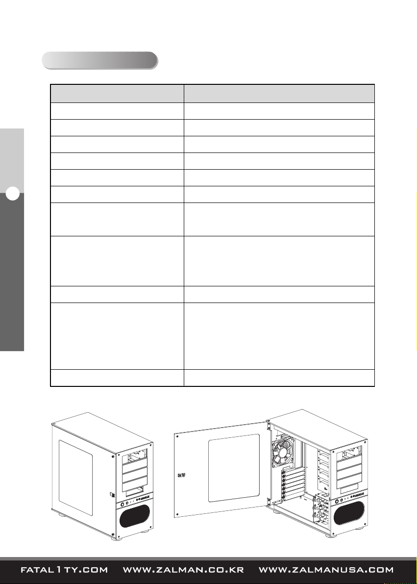
3. Specifications
3. Specifications
Category Description
Enclosure Dimensions
Weight
Material
Motherboard Compatibility
PSU Support
5.25 inch Bays
3.5 inch Bays
Cooling Components
Expansion Card Slots
Front I/O Ports
Available Color
480mm X 220mm X 430mm (L*W*H)
12.5 kg
Pure aluminum
ATX & microATX
ATX PSU
4 (Exposed)
1 (Exposed)
3 (Hidden)
1 X 120mm Rear RED LED fan
2 X 92mm Front RED LED fans
Fan Power Multi-Connector (ZM-MC1)
7 Slots
2 X USB2.0
1 X IEEE1394a
1 X Mic
1 X Headphones
Black
Page 6

5
English
4. Components
4. Components
Right-F Plate
ODD Bay Cover
FDD Bay Cover
HDD Chassis
DOOR
Page 7

6
English
4. Components
Diagrams Part Name Spec Qty Function
Allen Wrench
Spare
Allen Bolt
Cable Tie
Velcro Strip
M/B Stand off
PSU
Screw
PCI-e, PCI Slot
Screw
ODD, M/B
Screw
FDD Screw
Fan Power
MultiConnector
(ZM-MC1)
3mm
(Silver)
4*8
(Black)
(Blue)
Φ6*12*M3*3
(Silver)
FHM
Φ6-32*10
(Silver)
PHM
Φ6-32*7
(Silver)
PWHM 3*5
(Black)
PHM 3*8
(Black)
White = 5V
Black = 12V
1
2
5
2
6
9
47
2
1
For removing and reinstalling
the Right-F Plate during ODD
installation.
Spare Allen bolts for enclosure
maintenance.
For tidying cables.
Motherboard installation
For PSU Installation.
(For use with FC-ZE1 ONLY)
For securing PCI-e and PCI
cards to their slots.
(Relatively short)
For ODD, FDD, and
motherboard installation.
FDD Installation
For Front Fans’ RPM
Adjustment
1) Accessories
2) Fan Power Multi-Connector (ZM-MC1) Installation Guide
Connect the ZM-MC1 to the PSU’s 4-pin connector as illustrated in the diagram below.
This voltage adaptor is intended for use with the front intake fans.
Page 8

7
English
5. Installation Guide
① Open the Door, and place the PSU inside the enclosure.
② Tighten the PSU Screws from the outside.
5. Installation Guide
1) PSU Installation
PSU Screw
PSU
Page 9

8
English
5. Installation Guide
2) Motherboard Installation
① Lay the enclosure on its right side to install the motherboard.
② Align the motherboard with the standoff holes.
③ Fix the motherboard with the M/B Screws.
Note)
To install a microATX motherboard,
additional M/B Standoffs must first
be installed on the Right Plate before
installing the motherboard.
M/B Screw
M/B
M/B Standoff
Page 10

9
English
5. Installation Guide
3) ODD and FDD Installation
① Open the Door and remove the Right-F Plate with the provided Allen wrench.
② Remove the ODD / FDD Bay Cover(s) by unscrewing the ODD / FDD Bay Cover
Screws on either side.
③ Insert the ODD / FDD from the front.
④ Fix the ODD / FDD on both sides with the ODD / FDD Screws.
① Right-F Plate
③ ODD Screw
②
FDD Bay Cover
ODD Bay
Cover
Door
ODD / FDD Bay Cover
Screw Removal
FDD Screw
Page 11

10
English
5. Installation Guide
4) HDD Installation
(1) Basic Installation
※ Excessive pressure may damage the HDD Lock Bars. Please take cautionary
measures during HDD installation and removal.
① Open (raise) the HDD Lock Bar of the HDD Chassis’ bay where the HDD will be
installed.
② Slide in the HDD into the Bay and Close (lower) the HDD Lock Bar behind the HDD.
③ To remove the HDD, open (roll up) the HDD Lock Bar above the HDD.
HDD Lock Bar
HDD Lock Bar
Fixing Screw Hole
HDD Lock Bar
Fixing Screw
Mechanical Reference Hole
※ Zalman Internal Use ONLY
Page 12

11
English
5. Installation Guide
4) HDD Installation
(2) Locking Installation
Lock Groove
Align the HDD Lock Bar’s Lock Groove with
the Fixing Screw Hole.
Unscrew the HDD Lock Bar’s Fixing Screw
from the HDD Chassis.
Fixing Screw Hole
※ Pressing the HDD slightly into the HDD Chassis
with one hand, while rotating the HDD Lock Bar
with the other, allows easy alignment of the Lock
Groove and Fixing Screw Hole.
Screw in the Fixing Screw into the Fixing Screw
Hole to lock the HDD Lock Bar in place.
Page 13

12
English
5. Installation Guide
5) Front Panel Cables
※ Please refer to the motherboard’s manual on installation of Front Panel I/O cables,
before connecting the cables
※ The Power LED and the HDD LED will not function properly if they are connected
in the wrong polarity. Therefore, please check the motherboard manual before
making the connection.
IEEE1394a
USB2.0
AUDIO
Extra 5V Power
Extension
Switch Panel LED Power
HDD LED
Power LED
Power Button
RESET Button
Page 14

13
English
5. Installation Guide
※※
Precautions For Cable Connection
▶ Please refer to the motherboard’s manual for USB 2.0, IEEE1394a, and
audio connectors.
▶ Do not plug-in the USB2.0 connector into the IEEE1394a connector.
It may cause serious damage to all connected components.
▶ Do not plug-in the IEEE1394a connector into the USB2.0 connector.
It may cause serious damage to all connected components.
▶ Certain motherboards may have different orientation for the IEEE1394a,
USB2.0, and audio connectors than as illustrated in the diagram above.
Please refer to the motherboard’s manual before making any connections.
IEEE1394a
USB 2.0
AC 97 AZALIA(HD)
Page 15

 Loading...