


 Loading...
USER MANUAL

Item #626279
Rev C
Drawing # A626279
March 2009
©2009 YSI Incorporated.
The YSI, ProODO, and ODO logos are registered trademarks of YSI Incorporated.
Microsoft and Windows are registered trademarks of the Microsoft Corporation in the United States and other countries.
Pentium is a registered trademark of Intel Corporation.
C o n t e n t s |
|
Warranty............................................................................................................... |
i |
Introduction........................................................................................................ |
1 |
Getting Started.................................................................................................... |
1 |
Initial Inspection................................................................................. |
1 |
Battery Installation.............................................................................. |
1 |
Key Pad................................................................................................. |
2 |
Initial Setup ......................................................................................... |
4 |
Main Display........................................................................................ |
6 |
Menu Layout........................................................................................ |
6 |
Alpha/Numeric Entry......................................................................... |
7 |
System ................................................................................................................. |
8 |
Date/Time............................................................................................ |
8 |
GLP....................................................................................................... |
8 |
Language............................................................................................. |
12 |
Radix Point......................................................................................... |
12 |
Logging............................................................................................... |
13 |
Sampling Mode.................................................................................. |
13 |
Auto Shutoff....................................................................................... |
14 |
Backlight............................................................................................. |
14 |
SW Version (Software Version)....................................................... |
14 |
Serial #................................................................................................ |
14 |
Unit ID................................................................................................ |
14 |
Optical Dissolved Oxygen (ODO™)................................................................ |
15 |
ODO Probe Setup.............................................................................. |
15 |
Calibration - Dissolved Oxygen....................................................... |
18 |
Barometer.......................................................................................................... |
23 |
Display - Barometer.......................................................................... |
23 |
Calibration - Barometer.................................................................... |
23 |
Temperature...................................................................................................... |
24 |
Taking Measurements...................................................................................... |
24 |
Files and Site Lists............................................................................................. |
25 |
File Memory....................................................................................... |
25 |
View Data........................................................................................... |
25 |
Site List............................................................................................... |
26 |
Folder.................................................................................................. |
27 |
Delete Data......................................................................................... |
27 |
Data Manager Desktop Software..................................................................... |
27 |
Using the Communications Saddle................................................. |
27 |
Manage Logged Data ........................................................................ |
28 |
Real Time Data Collection............................................................... |
29 |
Configure Instruments...................................................................... |
29 |
Maintenance and Storage................................................................................. |
30 |
Updating Instrument and Probe Firmware.................................... |
30 |
General Maintenance - Battery Compartment Gasket................. |
30 |
Sensor Maintenance - Dissolved Oxygen........................................ |
30 |
Sensor Storage.................................................................................... |
34 |
Troubleshooting................................................................................................ |
34 |
Dissolved Oxygen Readings............................................................. |
34 |
Help .................................................................................................... |
35 |
Error/Status messages ...................................................................... |
35 |
Restore Default Calibration Values ................................................. |
36 |
Accessories / Part Numbers............................................................................. |
37 |
Declaration of Conformity.............................................................................. |
40 |
Recycling........................................................................................................... |
42 |
Contact Information........................................................................................ |
43 |
Ordering and Technical Support..................................................... |
43 |
Service Information........................................................................... |
43 |
Appendix A-DO% Calibration Values............................................................ |
44 |
Appendix B-Oxygen Solubility Table ............................................................ |
46 |

Wa r r a n t y
The YSI Professional ODO™ Instrument is warranted for three (3) years from date of purchase by the end user against defects in materials and workmanship, exclusive of batteries and any damage caused by defective batteries. ProODO™ field cable/probe assemblies are warranted for two (2) years from date of purchase by the end user against defects in material and workmanship. ProODO sensor caps are warranted
T h i s p a g e l e f t i n t e n t i o n a l l y b l a n k for one (1) year from date of purchase by the end user against defects in material and workmanship. ProODO systems (instrument & cable/probe assemblies) are warranted for 90 days from date of purchase by the end user against defects in material and workmanship when purchased by rental agencies for rental purposes. Within the warranty period, YSI will repair or replace, at its sole discretion, free of charge, any product that YSI determines to be covered by this warranty.
To exercise this warranty, call your local YSI representative, or contact YSI Customer Service in Yellow Springs, Ohio at +1 937 767-7241, 800-897-4151 or visit www. YSI.com (Support tab) for a Product Return Form. Send the product and proof of purchase, transportation prepaid, to the Authorized Service Center selected by YSI. Repair or replacement will be made and the product returned, transportation prepaid. Repaired or replaced products are warranted for the balance of the original warranty period, or at least 90 days from date of repair or replacement.
LIMITATION OF WARRANTY
This Warranty does not apply to any YSI product damage or failure caused by:
1. Failure to install, operate or use the product in accordance with YSI’s written instructions;
2. Abuse or misuse of the product;
3. Failure to maintain the product in accordance with YSI’s written instructions or standard industry procedure;
4. Any improper repairs to the product;
5. Use by you of defective or improper components or parts in servicing or repairing the product;
6. Modification of the product in any way not expressly authorized by YSI.
THIS WARRANTY IS IN LIEU OF ALL OTHER WARRANTIES, EXPRESSED OR
IMPLIED, INCLUDING ANY WARRANTY OF MERCHANTABILITY OR FITNESS
FOR A PARTICULAR PURPOSE. YSI’S LIABILITY UNDER THIS WARRANTY
IS LIMITED TO REPAIR OR REPLACEMENT OF THE PRODUCT, AND THIS
SHALL BE YOUR SOLE AND EXCLUSIVE REMEDY FOR ANY DEFECTIVE
PRODUCT COVERED BY THIS WARRANTY. IN NO EVENT SHALL YSI BE
LIABLE FOR ANY SPECIAL, INDIRECT, INCIDENTAL OR CONSEQUENTIAL
DAMAGES RESULTING FROM ANY DEFECTIVE PRODUCT COVERED BY
THIS WARRANTY.
i

I n t r o d u c t i o n
Thank you for purchasing the YSI Professional Optical Dissolved Oxygen (Pro ODO) instrument. The YSI ProODO™ measures dissolved oxygen in water using T h i s p a g e l e f t i n t e n t i o n a l l y b l a n k lifetime luminescence technology and uses a digital signal to send information between the instrument and probe. Key advantages of the new ProODO include the elimination of sensor flow dependence and sensor warm-up time, greater stability, the ability to zero the sensor for more accurate measurements at low dissolved oxygen levels, and the elimination of frequent membrane/electrolyte changes. The ProODO also features a waterproof (IP-67) case, a rugged MS-8 cable connector, backlit display and keypad, user-selectable cable lengths, USB connectivity, large memory with extensive site list capabilities, and a rugged, rubber over-molded case. For product specification information, please visit www.ysi.com or contact Technical Support at 800-897-4151 (+1 937 767-7241).
Reading the entire manual before use is recommended for an overall understanding of the instrument’s features.
G e t t i n g S t a r t e d
Initial Inspection
Carefully unpack the instrument and accessories and inspect for damage. Compare received parts with items on the packing list. If any parts or materials are damaged or missing, contact YSI Customer Service at 800-897-4151 (+1 937 767-7241) or the authorized YSI distributor from whom the instrument was purchased.
Battery Installation
The ProODO uses 2 alkaline C-cell batteries. Battery life depends on sampling mode and usage. When used in Manual Sampling mode, under normal conditions, battery life is approximately 80 hours at room temperature. The use of Automatic Sampling mode may slightly reduce the battery life. See the System section of this manual for more information on Sampling Modes.
|
Figure 1. ProODO with battery cover removed. Notice battery symbols indicating |
|
ii |
polarities. |
1 |
|
||

To install or replace the batteries:
1.Turn the instrument over to view the battery cover on the back.
2.Unscrew the four captive battery cover screws.
3.Remove the battery cover and install the new batteries, ensuring correct polarity alignment on the instrument or the removed cover (Figure 1).
4.Replace the battery cover on the back of the instrument and tighten the four screws. Do NOT over-tighten.
Key Pad
|
2 |
3 |
|
System |
Probe Calibration File |
1 |
|
4 |
|
|
|
13 |
|
|
12 |
|
5 |
11 |
|
6 |
10 |
|
7 |
9 |
|
8 |
|
|
Figure 2 |
Number |
Key |
Description |
1 |
|
System |
|
|
Opens System Menu from any screen. |
|
|
Use to adjust system settings. |
2 |
|
Probe |
|
|
Opens Probe Menu from any screen. |
|
|
Use to setup DO probe, sensor |
|
|
cap, and display units. |
3 |
|
Calibrate |
|
|
Opens Calibrate Menu from any screen. |
|
|
Use to calibrate dissolved oxygen. |
Number |
Key |
Description |
4 |
|
File |
|
|
Opens File Menu from any screen. |
|
|
Use to view data and GLP files, set up |
|
|
site and folder lists, and delete data. |
5 |
|
Backlight |
|
|
Press to turn the instrument backlight on and |
|
|
off and to adjust the display contrast when |
|
|
pressed with the left or right arrow key. |
6 |
|
Right Arrow |
|
|
Use to navigate right in alpha/numeric entry |
|
|
screens. Can be pressed simultaneously with |
|
|
Backlight button to increase display contrast. |
7 |
|
Down Arrow |
|
|
Use to navigate through menus and to navigate |
|
|
down in alpha/numeric entry screens. |
|
|
|
8 |
|
Power |
|
|
Press and hold for 2 seconds to |
|
|
turn the instrument on. |
|
|
Press to turn off. |
9 |
|
Help |
|
|
Press to receive hints & tips during operation. |
|
|
|
10 |
|
Enter |
|
|
Press to confirm selections, including |
|
|
alpha/numeric key selections. |
|
|
|
11 |
|
Left Arrow |
|
|
Use to navigate left in alpha/ |
|
|
numeric entry screens. |
|
|
Press to return to previous menu in all |
|
|
screens except alpha/numeric entry. |
|
|
Can be pressed simultaneously with Backlight |
|
|
button to decrease display contrast. |
12 |
|
Exit/Escape |
|
|
Exits back to Run Screen. |
|
|
When in alpha/numeric entry screen, |
|
|
escapes to previous menu. |
13 |
|
Up Arrow |
|
|
Use to navigate through menus and to |
|
|
navigate up in alpha/numeric entry screens |
|
|
|
2 |
3 |
Initial Setup
Throughout the manual, the term “probe” refers to the end of the cable where the sensor is located, the term “sensor” refers to the Optical Dissolved Oxygen sensing portion of the cable/probe assembly, and the term “sensor cap” refers to the removable sensing cap that is replaced about once per year (Figure 3).
Sensor |
Sensor Cap |
|
Probe
Figure 3
Unpacking the ODO Probe
Each ProODO cable/probe assembly and replacement ODO
isensor cap includes an instruction sheet with important information unique and specific to each individual sensing cap.
Remove the cable/probe assembly from the shipping container and locate the instruction sheet included with your assembly. This instruction sheet is important because it includes the calibration coefficients for your sensor cap. After using this sheet for general probe setup, be sure to store it in a safe place in case you need to reload these calibration coefficients in the unlikely event that they are ever deleted from the probe.
Note - A new cable/probe assembly already has a
isensor cap installed and the sensor cap coefficients are preloaded into the probe at the factory.
Preparing the probe for the first time:
1.Remove the metal probe guard from the probe by turning it counterclockwise.
2.Remove the red storage cap which contains a moist sponge from the end of the probe by pulling it straight off the sensor. Save this to use later for long term storage.
3.Reinstall the probe guard by sliding it carefully over the sensor and then threading it onto the cable/probe assembly with a clockwise rotation (Figure 4).
4.Locate the grey calibration/storage sleeve that was shipped with your probe/ cable assembly. Moisten the sponge in the grey calibration/storage with a small amount of clean water.
5.Slide the calibration/storage sleeve over the probe guard to keep the probe in a moist atmosphere for storage or calibration (Figure 5). It is important to always keep your sensor in a moist environment so the sensor cap does not dry out. (See Care, Maintenance, and Storage for more information.)
Figure 4 |
Figure 5 |
Connecting the Probe/Cable Assembly to the Instrument
To connect the cable, align the keys on the cable connector to the slots on the instrument connector. Push together firmly, then twist the outer ring until it locks into place (Figure 6). This MS-8 (Military Spec) connection is waterproof.
Figure 6. Note the keyed connector. The cable and instrument connectors can only be mated once the keyed sections are properly aligned. When disconnected, the cable connector and the connector on the instrument maintain an IP-67 rating.
4 |
5 |

Main Display
Press and hold the Power key  for two seconds to turn the instrument on. The instrument will briefly display two splash screens then go directly to the main run mode screen. The first time the instrument is powered up, you will need to set the date and time. Follow the instructions under the Setup | System | Date/Time section of this manual.
The display at the left shows the run mode (main display) with temperature in °C, barometric pressure in mmHg, DO in % and mg/L as the reported parameters. The date, time and battery level are indicated at the bottom of the screen. The logging preference of Log One Sample at a time is indicated at the top of the screen.
This screen also shows the message line towards the bottom of the display above the date and time. In this case, it doesn’t show a message. However, messages will appear frequently to indicate successful calibrations, saved configuration changes, etc.
A USB symbol will show up on the bottom of the display when connected through USB with the communications saddle. The instrument will display full
battery power when it is receiving power through the USB connection.
Contrast – the contrast adjustment can be accomplished
iby repeatedly pressing the backlight key and the left or right arrow key at the same time.
Menu Layout
Press Esc |
at anytime in the menus to escape back to the Run screen. The |
left arrow |
can be used to go back to the previous menu in all screens |
except alpha/numeric entry screens. You must use Esc to get out of the alpha/ numeric screens if you want to exit before finishing or without saving changes. Functions that are enabled appear as a circle with a dot . Disabled functions
appear as a circle only . In addition, some options appear as an empty box P or a box with a check mark Q.
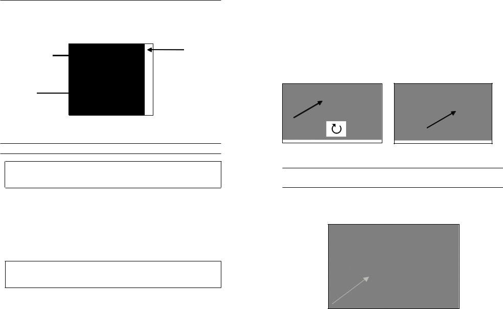
Alpha/Numeric Entry
The numeric screens will display numbers only (shown above, left). Alpha/ numeric screens will display numbers across the top and letters along the bottom rows (shown above, right). Letters appear as a common keyboard arrangement.
When an alpha or numeric character is required, the display will show the alpha/ numeric entry screen. To select a character, highlight it by using the arrows to move the highlight box over the desired selection. Then, press Enter on the keypad to confirm the selection. After confirming the selection, it will appear in the line at the top of the display.
For capital letters or lower case entry, highlight “SHIFT” and press Enter on the keypad to change the characters from upper to lower case.
To delete the entire line of the current entry, highlight )and press Enter on the
keypad. The !symbol functions as a backspace key in the alpha/numeric entry screens by deleting one character at a time. Use the “SPACE” function to add a space between characters.
When you have finished entering the correct information (16 character max), highlight <<<ENTER>>> at the bottom of the screen and press Enter on the keypad to confirm.
The |
key cannot be used to escape to the previous menu from |
|
i an alpha/numeric entry screen. Instead, use the |
key to go |
|
back to the previous menu when in alpha/numeric entry screens.
6 |
7 |
S y s t e m
Press System  to access any of the following menu items.
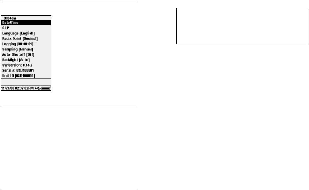
The System menu will allow you to access the setup options of the instrument including;
Date/Time, GLP, Language, Radix Point, Logging, Sampling, Auto Shutoff, Backlight, Sw (Software) Version, Serial #, and Unit ID. Any item with [brackets] shows the current setting inside the brackets. For instance, in the example at the left, Radix Point is currently set to [Decimal].
Date/Time
Highlight Date/Time from the System menu. Press enter to select.
Date Format – Highlight and press enter to open a sub menu for selecting the preferred date format: YY/MM/DD, MM/DD/YY, DD/MM/YY, or YY/DD/MM.
Date – Highlight and press enter to use the numeric entry screen to set the correct date.
Time Format – Highlight and press enter to open a submenu to select the preferred time format from 12-hour or 24-hour.
Time – highlight and press enter to use the numeric entry screen to set the correct time.
GLP
The GLP or ‘Good Laboratory Practice’ file saves detailed information about calibrations. It also includes diagnostic information about the sensors.
Calibrations are logged into a file, the GLP, for later review as needed. A single GLP file is utilized to store all calibration records and is capable of storing 500
records. Once the GLP file is full, the instrument will begin to overwrite the oldest record with each new calibration record.
In order to keep all of your GLP records, periodically download the GLP to Data Manager and export it to another program.
Otherwise, the instrument will overwrite the oldest record
ionce the memory is full. Also, since Data Manager saves GLP files under the Unit ID, you must periodically export and rename the GLP file on your PC or it will be overwritten each time you upload the GLP file from the instrument.
Several calibration parameters are saved for each calibration including optional ones that can be enabled by the user. Standard parameters include date/time stamp, calibration method, and sensor information. Optional, user selectable parameters include User ID, Probe ID, and User Fields 1 and 2.
In addition, there will be information specific to the Dissolved Oxygen or Barometer calibration record. A Dissolved Oxygen calibration record will contain the following calibration specific parameters:
DO
Sensor - Serial Number of the Sensor Calibration Method - Zero, %, or mg/L Cal Value
Sensor Value - Tangent of the angle between reference and signal LED, must be within 0.2 of the default value in the sensor, typically between
-0.53 and -2.17 Salinity Mode - Always manual
Salinity Value - Value entered by the user Barometer - Barometric Pressure during calibration Temperature - Temperature during calibration Calibrate Status - Calibrated
A Barometer calibration record will contain the following calibration specific parameters:
Barometer
Barometer - Calibrate value in kPa
Calibrate Status - Calibrated
8 |
9 |
Loading...