


 Loading...
6-Series
Multiparameter
Water Quality Sondes
User Manual
6-Series:
6600 V2 6600EDS V2 6920 V2 6820 V2 600 OMS V2 600XL 600XLM 600LS 600R 600QS

SAFETY NOTES
TECHNICAL SUPPORT AND WARRANTY INFORMATION
Contact information for technical support and warranty information on YSI’s Environmental Monitoring Systems products can be found in Section 9, Warranty and Service Information.
COMPLIANCE
When using the YSI 6-Series sondes in a European Community (CE) country, please be aware that electromagnetic compatibility (EMC) performance issues may occur under certain conditions, such as when the sonde is exposed to certain radio frequency fields.
If you are concerned with these issues, consult the Declaration of Conformity that was enclosed with your instrument. Specific conditions where temporary sensor problems may occur are listed in this document.
The Declaration of Conformity for your instrument can be found in Appendix H, EMC Performance. A similar document for YSI Model 650 is located at the end of Section 3, 650 MDS.
SPECIFICATIONS
For general specifications for all YSI Environmental Monitoring Systems products included in this manual, please see Appendix O, Specifications.
GENERAL SAFETY CONSIDERATIONS
For Health and Safety issues concerning the use of the calibration solutions with the sondes, please see Appendix A, Health and Safety.
NOTICE
Information contained in this manual is subject to change without notice. Effort has been made to make the information contained in this manual complete, accurate, and current. YSI shall not be held responsible for errors or omissions in this operations manual.
WARNING:
When caring for your sonde, remember that the sonde is sealed at the factory, and there is never a need to gain access to the interior circuitry of the sonde. In fact, if you attempt to disassemble the sonde, you would void the manufacturer's warranty.
TABLE OF CONTENTS
SECTION 1 INTRODUCTION |
|
|
|
1.1 ABOUT YSI |
|
1-1 |
|
1.2 HOW TO USE THIS MANUAL |
1-1 |
||
1.3 UNPACKING AND INSPECTION |
1.2 |
||
SECTION 2 SONDES |
|
|
|
2.1 |
GETTING STARTED |
|
2-1 |
2.2 |
CONNECTING YOUR SONDE |
2-2 |
|
2.3 |
PREPARING THE SONDE FOR USE |
2-5 |
|
2.4 |
ECOWATCH FOR WINDOWS – GETTING STARTED |
2-24 |
|
2.5 |
SONDE SOFTWARE SETUP |
2-25 |
|
2.6 |
GETTING READY TO CALIBRATE |
2-34 |
|
2.7 |
TAKING READINGS |
|
2-49 |
2.8 |
USING ECOWATCH TO UPLOAD AND ANALYZE DATA |
2-54 |
|
2.9 |
SONDE MENU |
|
2-68 |
2.10 CARE, MAINTENANCE, AND STORAGE |
2-111 |
||
SECTION 3 650 MDS DATA LOGGER |
|
||
3.1 INTRODUCTION |
|
3-1 |
|
3.2 GETTING STARTED |
|
3-1 |
|
3.3 SETTING UP THE 650 |
|
3-18 |
|
3.4 SONDE MENU INTERFACE |
3-21 |
||
3.5 LOGGING DATA WITH THE 650 |
3-27 |
||
3.6 MANAGING 650 FILES |
|
3-46 |
|
3.7 UPLOADING DATA FROM SONDES |
3-51 |
||
3.8 USING GPS WITH 650 |
|
3-51 |
|
3.9 USING THE 650 BAROMETER |
3-53 |
||
3.10 UPGRADING 650 SOFTWARE |
3-55 |
||
3.11 TROUBLESHOOTING |
|
3-56 |
|
3.12 FERRITE BEAD INSTALLATION |
3-57 |
||
3.13 SAFETY CONSIDERATIONS |
3-58 |
||
3.14 650 MDS SPECIFICATIONS |
3-61 |
||
SECTION 4 ECOWATCH FOR WINDOWS |
|
||
4.1 |
INTRODUCTION |
|
4-1 |
4.2 |
DATA ACQUISITION AND ANALYSIS |
4-7 |
|
4.3 ECOWATCH MENU |
|
4-12 |
|
SECTION 5 PRINCIPLES OF OPERATION |
|
||
5.1 |
CONDUCTIVITY |
|
5-1 |
5.2 |
SALINITY |
|
5-2 |
5.3 |
TOTAL DISSOLVED SOLIDS (TDS) |
5-2 |
|
5.4 |
OXIDATION REDUCTION POTENTIAL (ORP) |
5-3 |
|
5.5 pH |
|
5-4 |
|
5.6 DEPTH AND LEVEL |
|
5-6 |
|
5.7 TEMPERATURE |
|
5-7 |
|
5.8 DISSOLVED OXYGEN |
RAPID PULSE |
5-7 |
|
5.9 DISSOLVED OXYGEN |
ROX OPTICAL |
5-10 |
|
5.10 NITRATE |
|
5-12 |
|
5.11 AMMONIUM AND AMMONIA |
5-14 |
||
5.12 CHLORIDE |
|
5-16 |
|
5.13 TURBIDITY |
|
5-17 |
|
5.14 CHLOROPHYLL |
5-21 |
|
5.15 RHODAMINE |
5-28 |
|
5.16 PHYCOCYANIN-CONTAINING BLUE-GREEN ALGAE |
5-31 |
|
5.17 PHYCOERYTHRIN-CONTAINING BLUE-GREEN ALGAE |
5-37 |
|
5.18 FLOW |
5-42 |
|
SECTION 6 TROUBLESHOOTING |
|
|
6.1 CALIBRATION ERRORS |
6-1 |
|
6.2 SONDE COMMUNICATION PROBLEMS |
6-2 |
|
6.3 SENSOR PERFORMANCE PROBLEMS |
6-3 |
|
SECTION 7 COMMUNICATION |
|
|
7.1 OVERVIEW |
7-1 |
|
7.2 HARDWARE INTERFACE |
7-1 |
|
7.3 RS-232 INTERFACE |
7-2 |
|
7.4 SDI-12 INTERFACE |
7.2 |
|
SECTION 8 UPGRADING SONDE FIRMWARE |
8.1 |
|
SECTION 9 WARRANTY AND SERVICE INFORMATION |
|
|
9.1 LIMITATIONS OF WARRANTY |
9-1 |
|
9.2 AUTHORIZED SERVICE CENTERS |
9-2 |
|
9.3 CLEANING INSTRUCTIONS |
9-2 |
|
9.4 PACKING INSTRUCTIONS |
9-2 |
|
9.5 PRODUCT RETURN FORM |
9-4 |
|
APPENDIX A HEALTH AND SAFETY |
A-1 |
|
APPENDIX B |
REQUIRED NOTICE |
B-1 |
APPENDIX C ACCESSORIES AND CALIBRATION STANDARDS |
C-1 |
|
APPENDIX D SOLUBILITY AND PRESSURE/ALTITUDE TABLES |
D-1 |
|
APPENDIX E |
TURBIDITY MEASUREMENTS |
E-1 |
APPENDIX F |
FLOW |
F-1 |
APPENDIX G USING VENTED LEVEL |
G-1 |
|
APPENDIX H EMS PERFORMANCE |
H-1 |
|
APPENDIX I |
CHLOROPHYLL MEASUREMENTS |
I-1 |
APPENDIX J PERCENT AIR SATURATION |
J-1 |
|
APPENDIX K PAR SENSOR |
K-1 |
|
APPENDIX L PROTECTIVE ZINC ANODE |
L-1 |
|
APPENDIX M ROX OPTICAL DO SENSOR |
M-1 |
|
APPENDIX N NMEA APPLICATIONS |
N-1 |
|
APPENDIX O SPECIFICATIONS |
O-1 |
|

Introduction |
Section 1 |
SECTION 1 INTRODUCTION
1.1 ABOUT YSI INCORPORATED
From a three-man partnership in the basement of the Antioch College science building in 1948, YSI has grown into a commercial enterprise designing and manufacturing precision measurement sensors and control instruments for users around the world. Although our range of products is broad, we focus on three major markets: water testing and monitoring, health care, and bioprocessing.
In the 1950s, Hardy Trolander and David Case made the first practical electronic thermometer using a thermistor. This equipment was developed to supply Dr. Leland Clark with a highly sensitive and precise temperature sensor for the original heart-lung machine. The collaboration with Dr. Clark has been critical to the success of the company. In the 1960s, YSI refined a Clark invention, the membrane covered polarographic electrode, and commercialized oxygen sensors and meters which revolutionized the way dissolved oxygen was measured in wastewater treatment plants and environmental water. Today, geologists, biologists, environmental enforcement personnel, officials of water utilities and fish farmers recognize us as the leader in dissolved oxygen measurement.
In the 1970s, YSI again worked with Clark to commercialize one of his many inventions, the enzyme membrane. This development resulted in the first practical use of a biosensor, in the form of a membrane based on immobilized glucose oxidase, to measure blood sugar accurately and rapidly. In the next few years, this technology was extended to other enzymes, including lactate oxidase, for applications in biotechnology, health care, and sports medicine.
In the early 1990s, YSI launched a line of multi-parameter water monitoring systems to address the emerging need to measure non-point source pollution. Today we have thousands of instruments in the field that operate with the push of a button, store data in memory, and communicate with computers. These instruments (described in this manual) are ideal for profiling and monitoring water conditions in industrial and wastewater effluents, lakes, rivers, wetlands, estuaries, coastal waters, and monitoring wells. If the instrument has ‘on board’ battery power, it can be left unattended for weeks at a time with measurement parameters sampled at the user’s setup interval and data securely saved in the unit's internal memory. The fast responses of YSI’s sensors make the systems ideal for vertical profiling, and the small size of some our sondes allows them to fit down 2-inch diameter monitoring wells. All of YSI’s multi-parameter systems feature either the YSI-patented Rapid Pulse Dissolved Oxygen Sensor, which exhibits low-stirring dependence and provides accurate results without an expensive, bulky, and power-intensive stirrer or an ROX optical dissolved oxygen sensor which exhibits no flow dependence and is extremely stable in long-term deployments.
YSI has established a worldwide network of selling partners in over 50 countries that includes laboratory supply dealers, manufacturers' representatives, and YSI’s sales force. A subsidiary, YSI UK, distributes products in the United Kingdom, a sales office in Hong Kong supports YSI’s distribution partners in Asia Pacific, and YSI Japan supports distribution partners in Japan.
Through an employee stock ownership plan (ESOP), every employee is one of the owners. In 1994, the ESOP Association named YSI the ESOP Company of the Year. YSI is proud of its products and are committed to meeting or exceeding customers' expectations.
1.2 HOW TO USE THIS MANUAL
The manual is organized to let you quickly understand and operate the YSI 6-Series environmental monitoring systems. However, it cannot be stressed too strongly that informed and safe operation is more than just knowing which buttons to push. An understanding of the principles of operation, calibration
YSI Incorporated |
Environmental Monitoring Systems Manual |
1-1 |

Introduction |
Section 1 |
techniques, and system setup is necessary to obtain accurate and meaningful results. Thorough reading and understanding of this manual is essential to proper operation.
Because of the many features, configurations and applications of these versatile products, some sections of this manual may not apply to the specific system you have purchased.
If you have any questions about this product or its application, please contact YSI’s Technical Support Group or authorized dealer for assistance. See Section 9, Warranty and Service Information for contact information.
1.3 UNPACKING AND INSPECTION
Inspect the outside of the shipping box for damage. If any damage is detected, contact your shipping carrier immediately. Remove the equipment from the shipping box. Some parts or supplies are loose in the shipping box so check the packing material carefully. Check off all of the items on the packing list and inspect all of the assemblies and components for damage.
If any parts are damaged or missing, contact your YSI representative immediately. If you purchased the equipment directly from YSI, or if you do not know from which YSI representative your equipment was purchased, refer to Section 8, Warranty and Service Information for contact information.
YSI Incorporated |
Environmental Monitoring Systems Manual |
1-2 |

Sondes |
Section 2 |
SECTION 2 SONDES
2.1 GETTING STARTED
The 6-Series Environmental Monitoring Systems from YSI are multi-parameter, water quality measurement, and data collection systems. They are intended for use in research, assessment, and regulatory compliance applications. Section 2 concentrates on sondes and how to operate them during different applications. A sonde is a torpedo-shaped water quality monitoring device that is placed in the water to gather water quality data. Sondes may have multiple probes. Each probe may have one or more sensors that read water quality data.
The following list contains parameters that your sonde may measure. See Appendix O, Specifications for the specific parameters of each sonde.
Rapid Pulse Polarographic Dissolved Oxygen
ROX Optical Dissolved Oxygen
Conductivity
Specific Conductance
Salinity
Total Dissolved Solids
Resistivity
Temperature
pH
ORP
Depth
Level
Flow
Turbidity
Chlorophyll
Rhodamine WT
Phycocyanin-Containing Blue-green Algae
Phycoerythrin-Containing Blue-green Algae
Nitrate-N
Ammonia-N
Ammonium-N
Chloride
This section is designed to quickly familiarize you with the hardware and software components of the sondes and their accessories. You will then proceed to probe installations, cable connections, software installation and finally basic communication with your Sonde. Diagrams, menu flow charts and basic written instructions will guide you through basic hardware and software setup.
YSI Incorporated |
Environmental Monitoring Systems Operations Manual |
2-1 |
Sondes |
Section 2 |
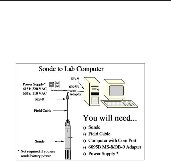
2.2 CONNECTING YOUR SONDE
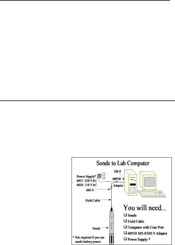
There are a number of ways in which you may connect the sondes to various computers, data collection devices and VT-100 terminal emulators. To utilize the configuration that will work best for your application, make sure that you have all of the components that are necessary. The following list and diagrams (Figures 1-4) are a few possible configurations.
Sonde to Lab Computer (recommended for initial setup)
Sonde to Data Collection Platform
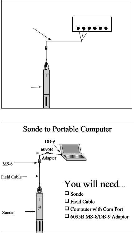
Sonde to Portable Computer
Sonde to YSI 650 MDS Display/Logger
Figure 1
YSI Incorporated |
Environmental Monitoring Systems Operations Manual |
2-2 |
Sondes |
Section 2 |
Figure 2
Sonde to Data Collection Platform
DCP
6096 MS-8 Adapter with Flying Leads
MS-8 
Field Cable 
+
-
|
YSI |
|
692 |
Sonde |
0 |
|
|
|
|
You will need...
Sonde
Field Cable
6096 Adapter with leads
Data Collection Platform
Figure 3
YSI Incorporated |
Environmental Monitoring Systems Operations Manual |
2-3 |

Sondes |
Section 2 |
Figure 4
Sonde to 650 Display/Logger
|
650 MDS |
MS-8 |
|
Field Cable |
You will need... |
Sonde
+
-
Field Cable
YS |
650 MDS Display/Logger |
I
Sonde  69
69
20
YSI 650 operates on C-cells or rechargeable batteries.
YSI Incorporated |
Environmental Monitoring Systems Operations Manual |
2-4 |
Sondes |
Section 2 |
2.3 PREPARING THE SONDE FOR USE
To prepare the sonde for calibration and operation, you need to install probes (sensors) into the connectors on the sonde bulkhead. In addition to probe installation, you need to install a new membrane on the YSI 6562 DO Probe if you are using this item. It is recommended that you install the DO membrane before installing the probe onto the bulkhead. For membrane changes in the future, you may be able to perform this operation without removing the DO probe. This will largely depend on whether the other installed probes interfere with your ability to install a membrane. The next step is providing power for the sondes, through batteries or line power, and then connecting a field cable. The four steps necessary for getting your sonde ready for use are listed below.
Step 1 Installing the Dissolved Oxygen Membrane – Section 2.3.1
Step 2 Installing the Probes – Section 2.3.2
Step 3 Supplying Power – Section 2.3.3
Step 4 Connecting a Field Cable – Section 2.3.4
2.3.1 STEP 1 - INSTALLING THE DISSOLVED OXYGEN MEMBRANE
Note: If you are using a ROX Optical DO sensor for your applications, please skip to Section 2.3.2 at this time.
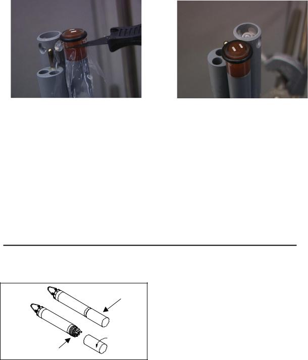
The 6562 Rapid Pulse Polarographic DO probe is shipped with a protective dry membrane on the sensor tip held in place by an O-ring. Remove the O-ring and membrane. Handle the probe with care. It is very important not to scratch or contaminate the sensor tip. See Section 2.10.2, Probe Care and Maintenance, for information on how often the membrane should be replaced.
Unpack the YSI 6562 DO Probe Kit and follow the instructions below.
Open the membrane kit and prepare the electrolyte solution. Dissolve the KCl in the dropper bottle by filling it to the neck with deionized or distilled water and shaking until the solids are fully dissolved. After the KCl is dissolved, wait a few minutes until the solution is free of bubbles.
Figure 5 |
|
Figure 6 |
|
1. |
ADD DI OR DISTILLED |
2. |
DRY MEMBRANE |
|
WATER |
||
|
|
|
PROTECTIVE CAP 
The DO membrane can be installed with the DO probe either free or installed in the sonde. Both methods are described in detail below. CAUTION: If you install the membrane with the probe not installed in the sonde, be sure that the protective cap is installed on the probe end away from the sensor face to ensure that the connector is not contaminated with electrolyte.
YSI Incorporated |
Environmental Monitoring Systems Operations Manual |
2-5 |
Sondes |
Section 2 |
DO MEMBRANE INSTALLATION WITH THE PROBE NOT INSTALLED IN THE SONDE
Remove the protective cap and the dry membrane from the YSI 6562 Dissolved Oxygen probe.
Make sure that the protective cap is installed on the connector end of the probe. Do not allow the electrolyte solution to wet the probe‟s connector and O-ring seal areas. This solution is extremely corrosive to the connector and is difficult to remove.
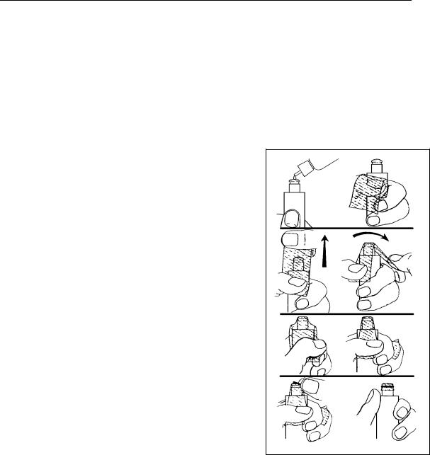
Before using any electrolyte, wrap a clean, dry paper towel around the capped probe to catch any spilled electrolyte. Hold the probe in a vertical position and apply a few drops of KCl solution to the tip. The fluid should completely fill the small moat around the electrodes and form a meniscus on the tip of the sensor. Be sure no air bubbles are stuck to the face of the sensor. If necessary, shake off the electrolyte and start over.
Secure a membrane between your left thumb and the probe body. Always handle the membrane with care, touching it only at the ends.
With the thumb and forefinger of your right hand, grasp the free end of the membrane. With one continuous motion, gently stretch it up, over, and down the other side of the sensor. The membrane should conform to the face of the sensor.
Secure the end of the membrane under the forefinger of your left hand.
Roll the O-ring over the end of the probe, being careful not to touch the membrane surface with your fingers. There should be no wrinkles or trapped air bubbles. Small wrinkles may be removed by lightly tugging on the edges of the membrane. If bubbles are present, remove the membrane and repeat steps 3-8.
Trim off any excess membrane with a sharp knife or scissors. Rinse off any excess KCl solution, but be careful not to get any water in the connector.
If you are concerned that electrolyte may have dripped onto the O- ring seal area, probe connector, or bulkhead connectors, rub the area clean with paper towels wetted with Deionized water and then dry the affected area with a final dry towel, compressed air blasts, or rinse with fresh alcohol.
Figure 7
3
4
5
6
7
8
NOTE: You may find it more convenient to mount the probe vertically in a vise with rubber jaws while applying the electrolyte and membrane to the sensor tip.
YSI Incorporated |
Environmental Monitoring Systems Operations Manual |
2-6 |
Sondes |
Section 2 |
DO MEMBRANE INSTALLATION WITH THE PROBE INSTALLED IN THE SONDE
Secure the sonde in a vertical position using a vise or a clamp and ring stand such that the sensors are upright. Remove the probe guard from the sonde.
Remove the old DO membrane and clean the probe tip with water and lens cleaning tissue. Make sure to remove any debris or deposits from the O-ring groove.
Using the dropper bottle of electrolyte supplied, place electrolyte on the DO probe tip until a high meniscus is formed as shown in Figure 8 below.
Figure 8 |
|
Figure 9 |
|
|
|
|
|
|
|
|
|
Hold the membrane so that all four corners are supported, but do not stretch the membrane laterally.
Position the membrane over the probe, keeping it parallel to the probe face as shown in Figure 9 above.
Using one continuous downward motion, stretch the membrane over the probe face as shown. See Figure 10 below. Do not hesitate to stretch the membrane.
Figure 10 |
|
Figure 11 |
|
|
|
|
|
|
|
|
|
Install a new O-ring by placing one side of the O-ring in the groove and rolling into place across the membrane and into the groove on the opposite side of the probe face. Avoid touching the probe face with
YSI Incorporated |
Environmental Monitoring Systems Operations Manual |
2-7 |
Sondes |
Section 2 |
your fingers. Once the O-ring is in position, squeeze it every 90 degrees to equalize the tension. See Figure 11 above. DO NOT USE GREASE OR LUBICANT OF ANY KIND ON THE O-RING.
Using a hobby knife or a scalpel, trim the excess Teflon from the membrane, making your cut about 1/8 inch below the O-ring as shown in Figure 12 below. A razor blade can be used for the cut if no knife or scalpel is available.
Figure 12 |
|
Figure 13 |
|
|
|
|
|
If the installation has been done properly, the finished product should have no bubbles, wrinkles, or tears as shown in Figure 13 above.
NOTE: Observe the following cautions to assure that your membrane installation is proper:
Secure the sonde tightly so that it will not move during membrane installation.
Wash hands before installation and do not allow finger oils or O-ring lubricant to touch the probe face or the membrane.
Use caution when replacing the probe guard that you do not touch the membrane. If you suspect that the membrane has been damaged, replace it immediately.
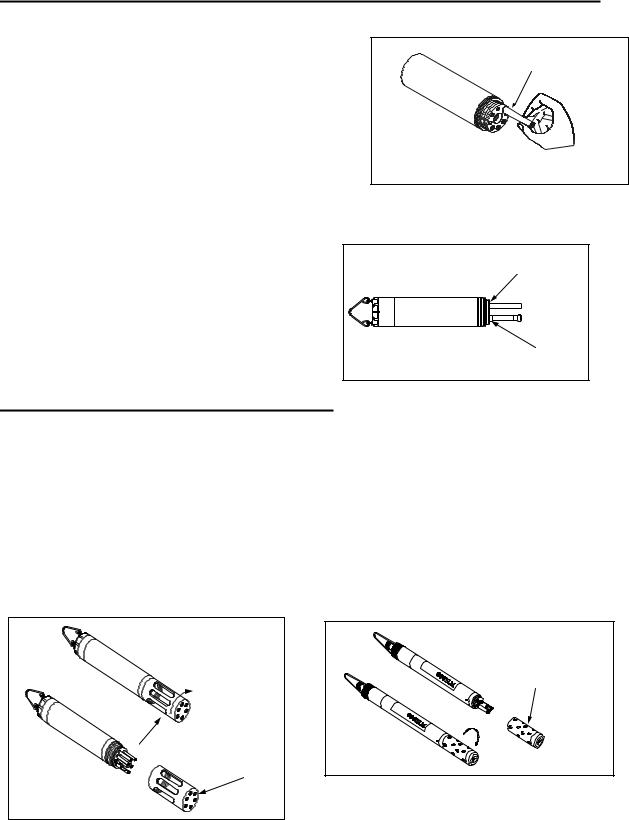
2.3.2 STEP 2 - INSTALLING THE PROBES
Remove the calibration cup from your sonde by hand as shown in Figure 14, to expose the bulkhead.
Figure 14
TRANSPORT CUP
BULKHEAD WITH
PROBE PORT PLUGS
YSI Incorporated |
Environmental Monitoring Systems Operations Manual |
2-8 |
Sondes |
Section 2 |
REMOVING THE PORT PLUGS
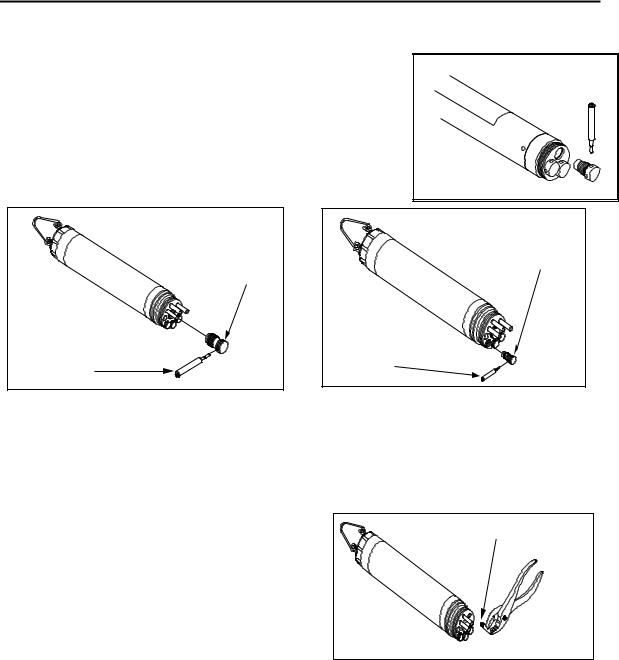
Using the long extended end of the probe installation tool supplied in the YSI 6570 Maintenance Kit, remove the port plugs. Save all the port plugs Figure 15 for possible future use.
There are a variety of probe options for the sondes. Figures 15, 16 and 17 illustrate the uses of the common tool for port plug removal.
Note that this tool will also be used to install the various probes.
If the tool is misplaced or lost, you may use 7/64” and 9/64” hex keys as substitutes.
|
DO, COND., & |
|
pH/ORP PORT |
OPTIC |
PLUGS |
PORT PLUG |
|
INSTALLATION |
INSTALLATION |
|
|
TOOL |
TOOL |
Figure 16 |
Figure 17 |
NOTE: You may need pliers to remove the ISE port plugs, but do not use pliers to tighten the ISE probes. Hand-tighten only.
Now refer to Figures 19-24 to find the probe locations in your sonde.
Figure 18
ISE PORT PLUG
PLIERS
(SLIP JAWS)
YSI Incorporated |
Environmental Monitoring Systems Operations Manual |
2-9 |
Sondes |
Section 2 |
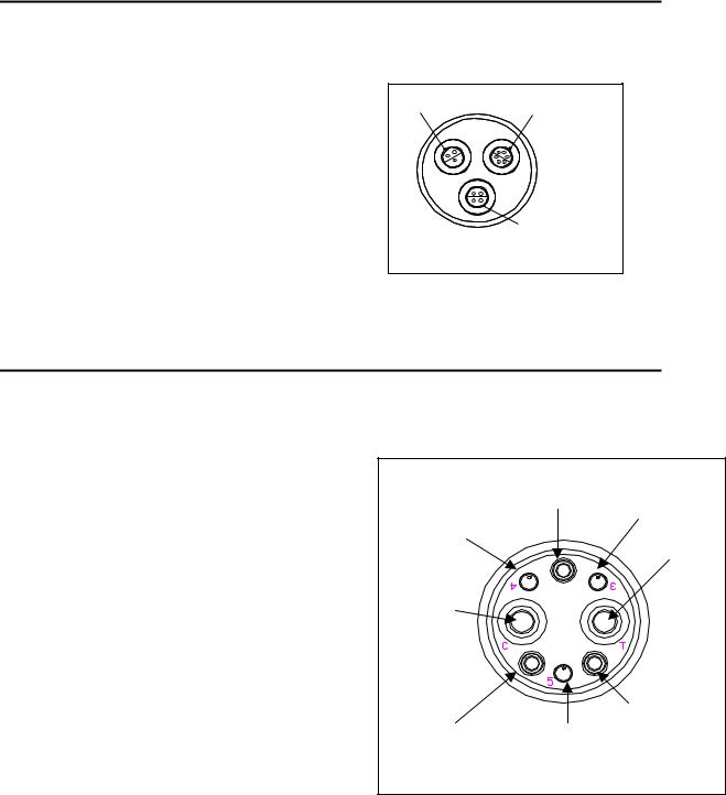
600XL & 600XLM SONDE BULKHEAD
3 Port Sonde: 1 Rapid Pulse DO, 1 Conductivity/Temperature, and 1 pH/ORP
|
|
|
Figure 19 |
|
|
|
6562 |
Dissolved oxygen probe = 3-pin connector |
DISSOLVED |
CONDUCTIVITY/ |
|
|
6560 |
Conductivity/Temperature = 6-pin connector |
|||
OXYGEN |
|||||
|
TEMPERATURE |
||||
6561 pH probe = 4 pin connector |
6562 |
||||
6560 |
|||||
|
6565 |
Combo pH/ORP probe = 4 pin connector |
|
|
|
|
|
|
|
ALL ISE |
|
|
|
|
|
PROBES |
|
6600V2-2 SONDE BULKHEAD
8 Port Sonde: 1 Rapid Pulse DO, 1 Conductivity/Temperature, 2 Optical, 3 ISE, 1 pH/ORP
|
Figure 20A |
|
|
6562 Dissolved oxygen probe = 3-pin connector |
|
|
|
6560 Conductivity/Temperature = 6-pin connector |
|
|
|
6561 or 6561FG pH probe = 4 pin connector |
|
Dissolved Oxygen |
|
6565 or 6565FG pH/ORP probe = 4 pin connector |
|
ISE‟s |
|
|
|
||
6566 Fouling Resistant pH/ORP probe = 4 pin connector |
ISE‟s |
|
Optic T |
6882 Chloride Probe = leaf spring connector |
|
||
|
|
||
6883 Ammonium Probe = leaf spring connector |
|
|
|
6884 Nitrate Probe = leaf spring connector |
|
|
|
6026 Turbidity Probe, Wiping = 8 pin connector |
Optic C |
|
|
6136 Turbidity Probe, Wiping = 8 pin connector |
|
|
|
6025 Chlorophyll Probe, Wiping = 8 pin connector |
|
|
|
6130 Rhodamine WT Probe, Wiping = 8 pin connector |
|
|
|
6150 Optical Dissolved oxygen probe = 8 pin connector |
|
|
|
6131 PC-Blue-green Algae probe = 8 pin connector |
|
|
|
6132 PE-Blue-green Algae probe = 8 pin connector |
|
|
|
|
Cond./Temp. |
|
pH/ORP |
|
ISE‟s |
|
|
|
|
|
YSI Incorporated |
Environmental Monitoring Systems Operations Manual |
2-10 |

Sondes |
Section 2 |
6600EDS V2-2 SONDE BULKHEAD
5 Port Sonde: 1 Rapid Pulse DO, 1 Conductivity/Temperature, 2 Optical, 1 pH/ORP
|
|
|
Figure 20B |
|
|
6562 |
Dissolved oxygen probe = 3-pin connector |
Rapid Pulse DO – 3 pin |
|
|
6560 |
Conductivity/Temperature = 6-pin connector |
||
|
6561 or 6561FG pH probe = 4 pin connector
6565 or 6565FG pH/ORP probe = 4 pin connector
6566 Fouling Resistant pH/ORP probe = 4 pin connector
6026 Turbidity Probe, Wiping = 8 pin connector
6136 Turbidity Probe, Wiping = 8 pin connector
6025 Chlorophyll Probe, Wiping = 8 pin connector
6130 Rhodamine WT Probe, Wiping = 8 pin connector
6150 Optical Dissolved oxygen probe = 8 pin connector
6131 PC-Blue-green Algae probe = 8 pin connector
6132 PE-Blue-green Algae probe = 8 pin connector
Cond//Temp – 6 pin
pH/ORP – 4 pin
6600V2-4 SONDE BULKHEAD
6 Port Sonde: 1 Conductivity/Temperature, 4 Optical, 1 pH/ORP
Cond/Temp – 6 pin
Figure 20C
6560 Conductivity/Temperature = 6-pin connector
6561 or 6561FG pH probe = 4 pin connector
6565 or 6565FG pH/ORP probe = 4 pin connector
6566 Fouling Resistant pH/ORP probe = 4 pin connector
6026 Turbidity Probe, Wiping = 8 pin connector
6136 Turbidity Probe, Wiping = 8 pin connector
6025 Chlorophyll Probe, Wiping = 8 pin connector
6130 Rhodamine WT Probe, Wiping = 8 pin connector
6150 Optical Dissolved oxygen probe = 8 pin connector
6131 PC-Blue-green Algae probe = 8 pin connector
6132 PE-Blue-green Algae probe = 8 pin connector
pH/ORP – 4 pin
YSI Incorporated |
Environmental Monitoring Systems Operations Manual |
2-11 |

Sondes |
Section 2 |
6820V2-1 & 6920V2-1 SONDE BULKHEADS
7 Port Sonde: 1 Rapid Pulse DO, 1 Conductivity/Temperature, 1 Optical, 1 pH/ORP, 3 ISE
|
|
Figure 21A |
|
|
|
6562 Dissolved oxygen probe = 3-pin connector |
|
COND/TEMP |
|
||
6560 Conductivity/Temperature = 6-pin connector |
|
|
|||
|
|
|
|||
|
6561 or 6561FG pH probe = 4 pin connector |
ISE1/ISE2 |
|
DISSOLVED |
|
|
pH/ORP |
|
|||
6565 or 6565FG pH/ORP probe = 4 pin connector |
|
OXYGEN |
|||
|
|
||||
6566 Fouling Resistant pH/ORP probe = 4 pin connector |
OPTICAL |
|
MOUNTING |
||
6882 Chloride Probe = leaf spring connector |
|
||||
|
|
SCREW |
|||
6883 Ammonium Probe = leaf spring connector |
|
3 |
|
||
|
6884 Nitrate Probe = leaf spring connector |
|
|
||
|
|
|
|
||
6026 Turbidity Probe, Wiping = 8 pin connector |
|
5 |
|
||
ISE3 |
4 |
ISE5 |
|||
|
|
||||
6136 Turbidity Probe, Wiping = 8 pin connector |
|
||||
|
|
|
|||
6025 Chlorophyll Probe, Wiping = 8 pin connector |
|
|
|
||
6130 Rhodamine WT Probe, Wiping = 8 pin connector |
|
ISE4 |
|
||
6150 Optical Dissolved oxygen probe = 8 pin connector
6131 PC-Blue-green Algae probe = 8 pin connector
6132 PE-Blue-green Algae probe = 8 pin connector
6820V2-2 & 6920V2-2 SONDE BULKHEADS
5 Port Sonde: 1 Conductivity/Temperature, 2 Optical, 1 pH/ORP, 1 ISE
Figure 21B
6560 Conductivity/Temperature = 6-pin connector
6561 or 6561FG pH probe = 4 pin connector
6565 or 6565FG pH/ORP probe = 4 pin connector
6566 Fouling Resistant pH/ORP probe = 4 pin connector
6882 Chloride Probe = leaf spring connector
6883 Ammonium Probe = leaf spring connector
6884 Nitrate Probe = leaf spring connector
6026 Turbidity Probe, Wiping = 8 pin connector
6136 Turbidity Probe, Wiping = 8 pin connector
6025 Chlorophyll Probe, Wiping = 8 pin connector
6130 Rhodamine WT Probe, Wiping = 8 pin connector
6150 Optical Dissolved oxygen probe = 8 pin connector
6131 PC-Blue-green Algae probe = 8 pin connector
6132 PE-Blue-green Algae probe = 8 pin connector
YSI Incorporated |
Environmental Monitoring Systems Operations Manual |
2-12 |
Sondes |
Section 2 |
600LS BULKHEAD
Figure 21C
If are working with a 600LS, all sensors will have been installed at the factory.
Conductivity |
Depth |
Temperature
600R BULKHEAD
If are working with a 600R sonde, your instrument will arrive with the probes installed.
Figure 22
TEMPERATURE
pH GLASS
pH REFERENCE 6850
CONDUCTIVITY
DISSOLVED
OXYGEN
600QS BULKHEAD
If are working with a 600QS sonde, your instrument will arrive with the probes installed.
Figure 23
TEMPERATURE
pH GLASS/ORP
pH REFERENCE 6850
CONDUCTIVITY
DISSOLVED
OXYGEN
YSI Incorporated |
Environmental Monitoring Systems Operations Manual |
2-13 |
Sondes |
Section 2 |
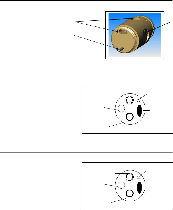
600 OMS V2-1 BULKHEAD
Figure 24
The conductivity sensor (module/port) for the
600 OMS V2-1 is factory installed. Optical probes (turbidity, chlorophyll, rhodamine WT, ROX optical DO, BGA-PC, and BGA-PE) are
threaded into the optical port on the bottom of the sonde by the user.
|
Conductivity Port |
Optical Port |
Temperature Sensor |
|
LUBRICATE O-RINGS
Apply a thin coat of O-ring lubricant, supplied in the YSI 6570 Maintenance Kit, to the O-rings on the connector side of each probe that is to be installed.
CAUTION: Make sure that there are NO contaminants
between the O-ring and the probe. Contaminants that are present under the O-ring may cause the O-ring to leak
when the sonde is deployed.
Figure 25
LUBRICATE O-RINGS |
NOTE: Before installing any probe into the sonde bulkhead, be sure that the probe port is free of moisture. If there is moisture present, you may use a can of compressed air to blow out the remaining moisture.
YSI Incorporated |
Environmental Monitoring Systems Operations Manual |
2-14 |
Sondes |
Section 2 |
INSTALLING THE TURBIDITY, CHLOROPHYLL, RHODAMINE WT , BGA-PHYCOCYANIN, BGAPHYCOERYTHRIN, AND ROX OPTICAL DISSOLVED OXYGEN PROBES
If you are using any of optical probes listed, it is recommended that the optical sensors be installed first. If you are not installing one of these probes, do not remove the port plug, and go on to the next probe installation.
|
Figure 26 |
All optical probes, 6136 turbidity, 6025 chlorophyll, 6130 |
|
Rhodamine WT, 6131 Phycocyanin Blue-green algae, 6132 |
OPTIC |
Phycoerythrin-Blue-green algae, and 6150 ROX Optical |
PROBE |
DO are installed in the same way. Install the probe into the |
|
center port, seating the pins of the two connectors before |
|
you begin to tighten. Tighten the probe nut to the bulkhead |
|
using the short extended end of the tool supplied with the |
INSTALLATION |
|
|
probe. Do not over-tighten. |
TOOL |
CAUTION: Be careful not to cross-thread the probe nut.
The YSI 6820V2-1 and 6920V2-1 sondes can accept a single turbidity, chlorophyll, Rhodamine WT, BGAPC, BGA-PE, or ROX DO probe. The 6600V2-2, 6600EDS V2-2, 6820V2-2, and 6920V2-2 sondes can accept and utilize two of the six optical sensors at the same time. The two optical ports of these sondes are labeled “T” and “C” on the sonde bulkhead. Each port can accept any of the six sensors so be sure to remember which sensor was installed in which port so that you will later be able to set up the sonde software correctly. The 6600V2-4 sonde can accept and utilize four of the six optical sensors at the same time. The four optical ports of this sonde are labeled “T” , “C”, “B”, and “O” on the sonde bulkhead. Each port can accept any of the six sensors so be sure to remember which sensor was installed in which port so that you will later be able to set up the sonde software correctly.
INSTALLING THE 6562 RAPID PULSE DISSOLVED OXYGEN PROBE, CONDUCTIVITY/TEMP AND pH/ORP PROBES
|
Figure 27 |
Insert the probe into the correct port and gently rotate the |
|
probe until the two connectors align. |
|
The probes have slip nuts that require a small probe |
DO PROBE |
|
|
installation tool to tighten the probe. With the connectors |
|
aligned, screw down the probe nut using the long extended |
|
end of the probe installation tool. Do not over-tighten. |
|
|
PROBE INSTALLATION |
CAUTION: Do not cross thread the probe nut. |
TOOL |
YSI Incorporated |
Environmental Monitoring Systems Operations Manual |
2-15 |
Sondes |
Section 2 |
INSTALLING THE ISE PROBES
Figure 28
The Ammonium, Nitrate and Chloride ISE probes do not have slip nuts and should be installed without tools. Use only your fingers to tighten. Any ISE probe can be installed in any of the three ports labeled “3”, “4”, and “5” on the sonde bulkhead of the 6820V2-1, 6920V2-1, and 6600V2-2 sondes or the single ISE port on the 6820V2-2 and 6920V2-2 bulkheads. Be sure to remember
which sensor was installed in which port so that you will later be able to set up the sonde software correctly.
ISE PROBE |
INSERT ISE PROBE, |
SCREW IN AND TIGHTEN WITH FINGERS. |
IMPORTANT: Make sure that the probe nut or probe body of the ISE probes are seated directly on the sonde bulkhead. This will ensure that connector seals will not allow leakage.
Figure 29
PROBE BODY TO SEAT |
ON BULKHEAD |
ISE PROBE |
DO PROBE |
PROBE NUT TO SEAT |
ON BULKHEAD |
INSTALLING THE PROBE GUARD
Included with each sonde is a probe guard. The probe guard protects the probes during calibration and measurement procedures. Once the probes are installed, install this guard by aligning it with the threads on the bulkhead and turn the guard clockwise until secure.
CAUTION: Be careful not to damage the Rapid Pulse DO membrane during installation of the probe guard.
Figure 30 shows the YSI 6820V2-1/6820V2-2/6920V2-1/6920V2-2 probe guard; the guard for the 6600V2-2/6600V2-4 is similar. The YSI 600R, 600QS, 600XL and 600XLM probe guards resemble Figure 31.
Figure 30
TURN CLOCKWISE BY |
HAND TO SECURE |
PROBE GUARD |
BULKHEAD |
(PROBES INSTALLED) |
Figure 31
PROBE GUARD
YSI Incorporated |
Environmental Monitoring Systems Operations Manual |
2-16 |
Sondes |
Section 2 |
2.3.3STEP 3 - POWER
Some type of external power supply is required to power the YSI 600R, 600QS, 600XL 6820V2-1, and the non-battery version of the 600 OMS V2-1sondes. The YSI 6920V2-1, 6920V2-2, 6600V2-2,
6600EDS V2-2, 6600V2-4, 600XLM, and battery version of the 600 OMS V2-1sondes have internal batteries or can run on external power.
If you have purchased a YSI 650 MDS display/logger, attaching your sonde to the display/logger will allow your sonde to be powered from the batteries or the external power of the display/logger. See Section 3, Displays/Loggers, for power options.
The battery-powered version of this instrument is powered by alkaline batteries, which the user must remove and dispose of when the batteries no longer power the instrument. Disposal requirements vary by country and region, and users are expected to understand and follow the battery disposal requirements for their specific locale.
The circuit board in this instrument contains a manganese dioxide lithium "coin cell" battery that must be in place for continuity of power to memory devices on the board. This battery is not user serviceable or replaceable. When appropriate, an authorized YSI service center will remove this battery and properly dispose of it, per service and repair policies.
POWER FOR LAB CALIBRATION
A YSI 6038 (110 VAC) or 6651 (64-240 VAC) Power Supply is required for sondes without internal batteries when using them with a PC for calibration and setup. Sondes with internal batteries do not require a power supply, but using the sonde with a power supply in the lab is often convenient and extends battery life. Most adapters include a short pigtail for power that plugs into the power supply. After attaching the four-pin connector from the power supply to the pigtail, simply plug the power supply into the appropriate AC outlet.
See Section 2.2, Connecting Your Sonde, for specific information on cables, adapters and power supplies required for connecting your sonde to various devices.
Figure 32
The system configuration best suited for initial setup is shown in Figure 32.
YSI Incorporated |
Environmental Monitoring Systems Operations Manual |
2-17 |
Sondes |
Section 2 |
INSTALLING BATTERIES
The 600XLM, 6600V2-2, 6600EDS V2-2, 6600V2-4, 6920V2-1, 6920V2-2 and battery version of the 600 OMS V2-1are the sondes that use alkaline batteries for power. A set of batteries is supplied with each of these sondes. If you do not have one of these sonde model types, you may skip this section.
INSTALLING BATTERIES INTO THE YSI 600XLM OR 600 OMS V2-1 SONDES
To install 4 AA-size alkaline batteries into the sonde, refer to the following directions and Figure 33.
Grasp the cylindrical battery cover and unscrew by hand. Then slide the battery lid up and over the bulkhead connector. Insert batteries, paying special attention to polarity. Labeling on the battery compartment posts describes the orientation. It is usually easiest to insert the negative end of battery first and then “pop” the positive terminal into place.
Check the O-ring and sealing surfaces for any contaminants that could interfere with the O-ring
seal of the battery chamber.
CAUTION: Make sure that there are NO contaminants between the O-ring and the sonde. Contaminants that are present under the O-ring may cause the O-ring to leak when the sonde is deployed.
Lightly lubricate the o-ring on the outside of the battery cover. DO NOT lubricate the internal o-ring.
Return the battery lid and tighten by hand.
DO NOT OVER-TIGHTEN.
Figure 33
|
DO NOT USE BAIL FOR LEVERAGE |
|
BULKHEAD |
WHEN REMOVING BATTERY CAP! |
|
|
||
CONNECTOR |
BAIL |
|
|
||
BATTERY |
|
|
CAP |
SONDE |
|
|
||
|
BODY |
|
Figure 34 |
|
|
|
BAIL |
|
BULKHEAD |
SCREW ON |
|
CONNECTOR |
||
BATTERY CAP |
||
WITH CAP |
||
|
SONDE BODY |
|
AA BATTERIES x 4 |
|
||
(NOT SHOWN) |
(NOTE POLARITY) |
|
YSI Incorporated |
Environmental Monitoring Systems Operations Manual |
2-18 |
Sondes |
Section 2 |
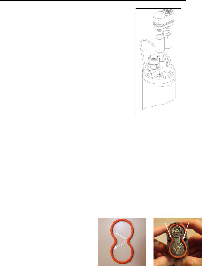
INSTALLING BATTERIES INTO THE YSI 6600V2-2, 6600EDS V2-2, AND 6600V2-4 SONDES
Figure 35
IMPORTANT SAFETY FEATURE: The 116003 battery lid for the 6600V2-2, 6600EDS V2-2, and 6600V2-4 is equipped with a safety pressure-release valve. The valve will vent off any pressure build up in the battery compartment from waste gas that could be created by battery failure, improperly marked or installed batteries, flooding, and dead or heavily discharged batteries. Pressure from the waste gas can deform the battery compartment and cause the sonde to shatter, projecting fragments from the sonde casing in all directions. People near a sonde that shatters could suffer serious puncture wounds and serious eye injuries. DO NOT defeat this safety feature by blocking the valve or painting over or in close proximity to the valve. DO NOT attempt to disassemble the safety valve.
Install 8 C-size alkaline batteries according to the following directions and
Figure 35.
Using the 9/64” hex driver supplied with the 6600V2-2, 6600EDS V2-2 and 6600V2-4 loosen the battery lid screws.
NOTE: The battery lid screws are captive. It is not necessary to remove them from the lid completely.
Remove the battery lid and install the batteries, as shown. If installing or replacing the batteries, test batteries for proper polarity and voltage and observe the correct polarity before installing the batteries into the battery chamber.
CAUTION: Be sure the orange O-ring is installed in the groove of the lid. The o-ring is designed with retention tabs to prevent it from falling out of the grove during installation. Check the O-ring and sealing surfaces for any contaminates which could interfere with the O-ring seal of the battery chamber. Remove any contaminates present. Also clean the protective O-rings which are located the side of the battery lid. Apply a small amount of grease to the threads of each screw to prevent binding. See the next section and Figures 35A through 35L for details on proper installation of the battery lid o-ring.
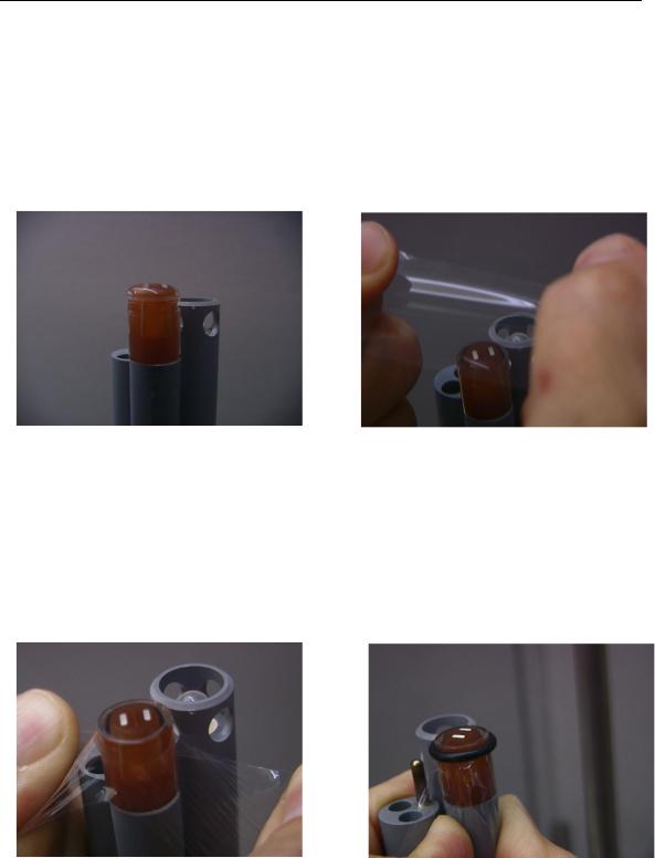
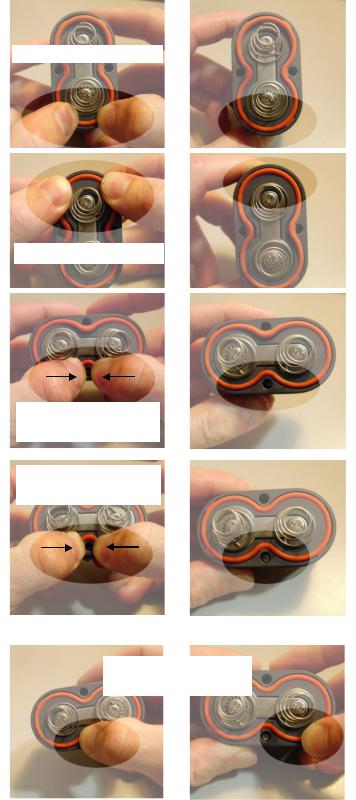
The updated face seal for the 6600 sonde battery lid incorporates six retaining tabs to hold the face seal in the seal groove during installation, allowing consistent and effective sealing after battery replacement. In order for this feature to work properly, the retaining tabs must be correctly seated in the battery lid‟s seal groove to prevent it from becoming dislodged during handling. If the seal is not installed correctly it can fall out of its groove during battery lid installation and then can be crushed during assembly. This may cause damage to the seal and cause battery compartment flooding when the sonde is deployed. The following procedure is a recommended method to properly retain the seal in its groove:
1. Place seal on the battery lid groove so that it |
|
|
|
|
|
|
|
|
Middle tabs |
|
|
follows the profile of the groove and is centered |
|
|
|
|
|
|
|
|
|
|
|
|
|
|
|
|
|
about the two middle retaining tabs. |
|
|
|
|
|
|
|
|
|
||
|
Retaining Tabs |
|
|
|
|
Figures 35A and 35B |
|
|
|
|
|
|
|
Align seal to groove |
|||
|
|
|
|||
YSI Incorporated |
Environmental Monitoring Systems Operations Manual |
2-19 |
Sondes |
Section 2 |
2.Press two of the outermost retaining tabs down into the groove. It should be clear that the retaining tabs have recessed into the groove along with the seal so that the tabs outermost edges are at or below the battery lid‟s mounting surface.
Figures 35C and 35D
3.Press the remaining two outermost retaining tabs into the groove and check to make sure the tabs have been recessed as before. Verify that the other two previously seated retaining tabs have not been forced from their position in the groove.
Figures 35E and 35F
4.Place your thumbs on the seal about a ¼” or so from the sides of the center retaining tab and press the seal down into the groove while sliding your thumbs towards each other. This stretches the seal to fit the profile of the groove allowing the center tab to be seated properly. You may need to use the tip of one of your thumbs to finish pressing the tab into place.
Figures 35G and 35H
5.Press the remaining middle retaining tab into the groove as before and verify that none of the other retaining tabs have been forced from their positions in the groove during this part of the seal installation.
Figures 35I and 35J
6.To ensure that all the retaining tabs are properly seated in the seal groove you can apply pressure to the seal forcing it into the groove at the location of each tab. This will further seat each tab into the groove allowing it to capture the seal.
Figures 35K and 35L
Press tabs into groove
Press tabs into groove
Stretch seal and press tab into groove
Stretch seal and press tab into groove
Press on tabs to verify they have been seated
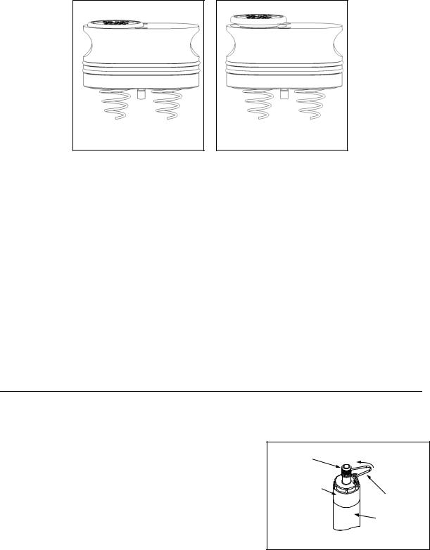
CAUTION: Before installing the battery lid, ensure that the pressure release valve is closed. If the pressure release valve is open, DO NOT install (see Figures 35M and 35N). The valve
YSI Incorporated |
Environmental Monitoring Systems Operations Manual |
2-20 |
Sondes |
Section 2 |
cannot be reset and the battery lid must be replaced before sonde deployment. Contact YSI Technical Support for instructions.
Figure 35M: Closed valve OK to Deploy
Figure 35N: Open valve DO NOT Deploy
Lightly lubricate the o-rings on the outside of the battery cover. DO NOT lubricate the orange internal o- ring.
Return the battery lid and HAND tighten the screws with the hex driver until snug. DO NOT OVER TIGHTEN.
CAUTION: Over-tightening the screws may cause the battery compartment to flood. Do NOT use power tools to tighten the battery lid screws.
With the battery cover installed and secured, check the battery voltage in the sondes Status Menu. The voltage must be 12.0 volts or higher with new cells. A voltage less then 12.0 volts could indicate that a cell was installed upside down or that one of the cells is not at full strength.
CAUTION: Remove Batteries When Not in Use. As with any battery-powered instrumentation, batteries should be removed before short or long-term storage. Even with the new battery lid, batteries can leak, releasing toxic and corrosive battery acid and damaging equipment.
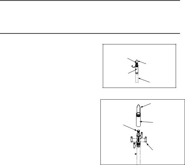
INSTALLING BATTERIES IN THE 6920V2-1 AND 6920V2-2 SONDES
To install the 8 AA-size alkaline batteries into the sonde, refer to the following directions and Figures 36 and 37.
Position the bail so that it is perpendicular to the sonde and use it as a lever to unscrew the battery cap by hand. Then slide the battery lid up and over the bulkhead connector.
Insert batteries, paying special attention to polarity. Labeling on the top of the sonde body describes the orientation.
Figure 36
BULKHEAD CONNECTOR
WITH CAP
BATTERY CAP
BAIL
SONDE BODY
GRASP BAIL WITH HAND.
TURN COUNTERCLOCKWISE TO LOOSEN.
YSI Incorporated |
Environmental Monitoring Systems Operations Manual |
2-21 |
Sondes
Check the O-rings and sealing surfaces for any contaminants that could interfere with the seal of the battery chamber.
CAUTION: Make sure that there are NO contaminants between the O-ring and the sonde. Contaminants that are present under the O-ring may cause the O-ring to leak when the sonde is deployed.
Lightly lubricate the o-rings on the bottom of the threads and on the connector stem as shown in Figure 37.
Return the battery lid and tighten by hand. DO NOT OVERTIGHTEN.
|
Section 2 |
|
BATTERY CAP |
|
BAIL |
|
|
|
BULKHEAD |
|
|
CONNECTOR |
+ |
|
- |
O-RINGS |
|
|
|
|
+ |
|
|
Figure 37
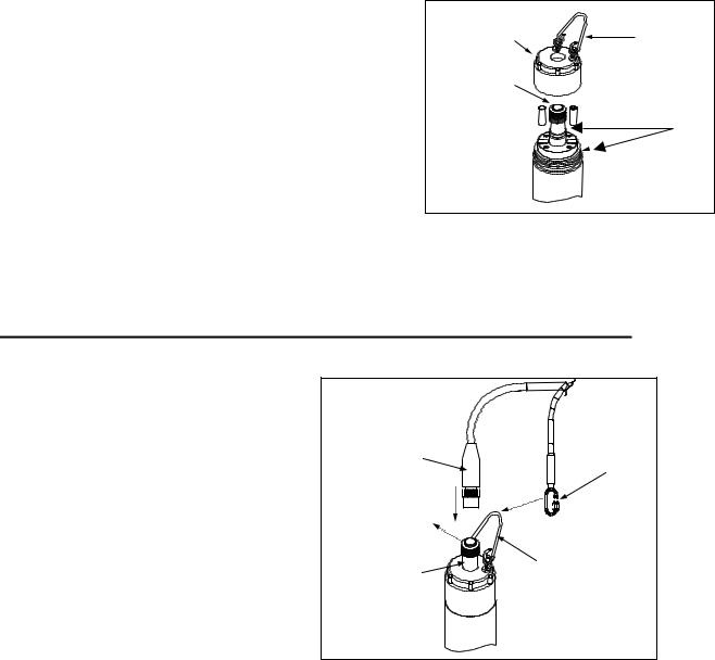
2.3.4 STEP 4 - CONNECTING A FIELD CABLE
All YSI 6600V2-2, 6600EDS V2-2, 6600V2-4, 6920V2-1, 6920V2-2, 6820V2-2, 600XLM, 600QS, and 600 OMS V2-1sondes have a sonde-mounted cable connector for attachment of the field cable. Some versions of the 600R, 600XL, and 6820V2-1 sondes also have this connector.
However, some versions of the YSI 600R, 600XL, and 6820V2-1sondes have permanently attached
“integral” cables. If your sonde has a cable that is non-detachable, the next section will not be relevant.
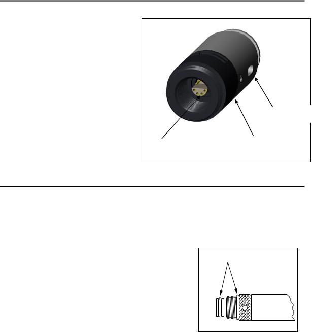
To attach a field cable to the sonde connector, remove the waterproof cap from the sonde connector and set it aside for later reassembly during deployment or storage. Then connect your field cable to the sonde connector.
Figure 38
FIELD CABLE |
STRAIN RELIEF |
CONNECTOR |
CONNECTOR |
REMOVE |
|
WATERPROOF CAP |
|
SONDE |
BAIL |
|
|
CONNECTOR |
|
A built-in “key” will ensure proper pin alignment. Rotate the cable gently until the “key” engages and then tighten the connectors together by rotating clockwise. Attach the strain relief connector to the sonde bail. Rotate the strain relief connector nut to close the connector's opening.
For all of the sondes, the other end of the cable is a military-style 8-pin connector (MS-8). Through use of a YSI 6095B MS-8 to DB-9 adapter, the sonde may be connected to a computer for setup, calibration, realtime measurement, and uploading files.
This MS-8 connector also plugs directly into the 650 MDS display/logger. This instrument contains a microcomputer that allows it to be used in a similar manner to that of a terminal interface to a PC.
As an alternative to the field cable, you may use a YSI 6067B calibration cable for laboratory interaction with the sonde. In this case, simply plug the proper end of the cable into the sonde connector and attach the DB-9 connector of the cable to the Com port of your computer.
YSI Incorporated |
Environmental Monitoring Systems Operations Manual |
2-22 |
Sondes |
Section 2 |
CAUTION: The 6067B cable is for laboratory use only -- it is not waterproof and should not be submersed!
Sondes that are equipped with level sensors use vented cables. See Appendix G, Using Vented Level, for detailed information.
YSI Incorporated |
Environmental Monitoring Systems Operations Manual |
2-23 |

Sondes |
Section 2 |
2.4 ECOWATCH FOR WINDOWS -GETTING STARTED
This section will describe how to get started with EcoWatch for Windows, but detailed information is provided in Section 4, EcoWatch for Windows, or a convenient Windows Help section that is part of the software. It is recommended that you thoroughly read Section 4 or use the Help function for a comprehensive understanding of EcoWatch for Windows.
2.4.1INSTALLING ECOWATCH FOR WINDOWS
EcoWatch for Windows software must be used with an IBM-compatible PC with a 386 (or better) processor. The computer should also have at least 4MB of RAM and Windows Version 3.1 or later.
Place the EcoWatch for Windows compact disk in your CD ROM drive. Select Start, then Run and type d:\setup.exe at the prompt. Press Enter or click on “OK” and the display will indicate that EcoWatch is proceeding with the setup routine. Simply follow the instructions on the screen as the installation proceeds.
2.4.2RUNNING ECOWATCH FOR WINDOWS
To run EcoWatch for Windows, simply select the EcoWatch icon on your desktop or from the Windows Program Menu. For help with the EcoWatch program, see Section 4, EcoWatch or use the Help section of the software.
2.4.3ECOWATCH FOR WINDOWS SETUP
To setup the EcoWatch software for use with a sonde, select the sonde icon  on the toolbar, and then the proper Com port to which your sonde is connected. If the default setting is correct, it does not need to be changed. Click “OK” to open a terminal window.
From the Comm Menu, select the Settings option to check the baud rate. The baud rate should be 9600. If it is not, select 9600 from the list and press Enter.
From the Settings Menu, select the Font/Color and Background Color options to choose a color scheme for the EcoWatch for Windows menus.
YSI Incorporated |
Environmental Monitoring Systems Operations Manual |
2-24 |
Loading...