


 Loading...
Operations Manual
EcoSense® DO200
Field/Lab
Dissolved Oxygen
and Temperature
Instrument
• English
• Français
• Español
• Deutsch
• Italiano
WARRANTY
The EcoSense® DO200 Instrument is warranted for one year from date of purchase by the end user against defects in materials and workmanship. DO200 probes and cables are warranted for one year from date of purchase by the end user against defects in material and workmanship. Within the warranty period, YSI will repair or replace, at its sole discretion, free of charge, any product that YSI determines to be covered by this warranty.
To exercise this warranty, write or call your local YSI representative, or contact YSI Customer Service in Yellow Springs, Ohio. Send the product and proof of purchase, transportation prepaid, to the Authorized Service Center selected by YSI. Repair or replacement will be made and the product returned, transportation prepaid. Repaired or replaced products are warranted for the balance of the original warranty period, or at least 90 days from date of repair or replacement.
Limitation of Warranty
This Warranty does not apply to any YSI product damage or failure caused by: (i) failure to install, operate or use the product in accordance with YSI’s written instructions; (ii) abuse or misuse of the product; (iii) failure to maintain the product in accordance with YSI’s written instructions or standard industry procedure; (iv) any improper repairs to the product; (v) use by you of defective or improper components or parts in servicing or repairing the product; or (vi) modification of the product in any way not expressly authorized by YSI.
THIS WARRANTY IS IN LIEU OF ALL OTHER WARRANTIES, EXPRESSED OR IMPLIED, INCLUDING ANY WARRANTY OF MERCHANTABILITY OR FITNESS FOR A PARTICULAR PURPOSE. YSI’s LIABILITY UNDER THIS WARRANTY IS LIMITED TO REPAIR OR REPLACEMENT OF THE PRODUCT, AND THIS SHALL BE YOUR SOLE AND EXCLUSIVE REMEDY FOR ANY DEFECTIVE PRODUCT COVERED BY THIS WARRANTY. IN NO EVENT SHALL YSI BE LIABLE FOR ANY SPECIAL, INDIRECT, INCIDENTAL OR CONSEQUENTIAL DAMAGES RESULTING FROM ANY DEFECTIVE PRODUCT COVERED BY THIS WARRANTY.
CONTACT INFORMATION
YSI Inc. • 1725 Brannum Lane • Yellow Springs OH, 45387 800-897-4151 • 937-767-7241 • Fax: 937-767-1058
Email: ecosense@ysi.com • Website: www.ysiecosense.com
1
CONTENTS |
|
WARRANTY.................................................................................................... |
1 |
CONTACT INFORMATION............................................................................. |
1 |
GENERAL INTRODUCTION........................................................................... |
3 |
INITIAL INSPECTION ..................................................................................... |
3 |
PRECAUTIONS .............................................................................................. |
3 |
The Case .................................................................................................. |
3 |
The Probe ................................................................................................. |
3 |
PROBE PREPARATION................................................................................. |
4 |
BATTERY INSTALLATION ............................................................................. |
4 |
THE KEYPAD.................................................................................................. |
4 |
THE LCD DISPLAY......................................................................................... |
5 |
OPERATIONAL PROCEDURES .................................................................... |
5 |
MEASUREMENT MODES .............................................................................. |
5 |
CALIBRATION SET-UP .................................................................................. |
5 |
Requirements............................................................................................ |
5 |
Procedure ................................................................................................. |
6 |
PROBE MAINTENANCE................................................................................. |
6 |
TROUBLESHOOTING .................................................................................... |
7 |
SPECIFICATIONS .......................................................................................... |
7 |
CONVERSIONS.............................................................................................. |
7 |
RECOMMENDED SPARE PARTS LIST ........................................................ |
7 |
2
GENERAL INTRODUCTION
The DO200 is one of three instruments in the EcoSense® product line from YSI. The DO200 is a precise tool that measures dissolved oxygen in % and ppm (mg/L) and temperature. A built-in microprocessor stores, calculates, and compensates for all parameters related to DO determinations including DO electrode temperature characteristics.
This unit has a splash-resistant IP65 case. The mechanical touch keys are highly reliable with tactile and audio feedback. This instrument uses one 9V battery. Re-calibration is not required when power is restored.
The front of the instrument has a large LCD that displays DO %, ppm, and temperature simultaneously along with user prompts and mode indicators. The unit prompts the user through calibration and measurement procedures.
The model DO200 field and lab probes use a polarographic electrode with convenient screw-on cap membranes. The 200-4 and 200-10 field probes come with a built-in temperature probe for automatic temperature compensation, as well as a stainless steel body for added weight. The 200-BOD lab probe comes with a power supply and includes self-stirring and replaceable electrodes.
Other features include long battery life and high 50/60 Hz AC noise rejection. This instrument is universal and user-friendly for field, industrial, and laboratory applications.
INITIAL INSPECTION
Carefully unpack the unit and accessories, and inspect for shipping damages. Compare received parts with materials listed on the packing list. Notify YSI immediately of any damage or missing parts. Save all packing materials until satisfactory operation is confirmed.
PRECAUTIONS
The Case
Though the DO200 instrument is housed in a splash-proof IP65 case, DO NOT use it underwater; the connector is not waterproof. The splash-resistant case prevents permanent damage to the unit if accidentally sprayed with non-corrosive solutions. In case of submersion, follow these steps immediately:
1.Dry the connector if necessary, and replace the DO probe. Rinse unit carefully with distilled water. After rinsing and drying, inspect and clean connectors to remove all contaminants that may affect probe connections.
2.Wait for unit and probe to dry completely before resuming operation.
3.If the unit does not function correctly after steps 1 and 2, call YSI for possible repair or replacement (see Warranty).
The Probes (Field & Lab)
1.Membranes last longer if properly installed and regularly maintained. Erratic readings can result from damaged or fouled membranes or from large bubbles in the electrolyte reservoir. If unstable readings or membrane damage occurs, replace both the membrane cap and Oxygen Probe solution (also known as “O2 Probe Electrolyte”, potassium chloride, or KCl solution). The average replacement interval is 4 to 8 weeks, although they may last longer if kept clean. Harsh environments, such as wastewater, may require membrane replacement every 2 to 4 weeks. Unstable readings may occur if membrane cap is coated with oxygen consuming or oxygen evolving organisms such as bacteria or algae.
2.Chlorine, sulfur dioxide, nitric oxide and nitrous oxide can affect readings by behaving like oxygen at the probe.
3.Avoid substances that may damage probe materials such as concentrated acid, caustics and strong solvents. Probe materials include Stainless steel, epoxy and ABS Plastic.
3
4.Keep the probe’s gold cathode clean and textured (when properly maintained it has a matte finish). If it is tarnished (from contact with certain gases), or plated with silver (from extended use with a loose or wrinkled membrane), then clean it, following the instructions in “Probe Maintenance”.
5.To prevent the membrane and electrolyte from drying out, store the field probe in the calibration bottle with the moistened sponge and the lab probe in a BOD bottle with 1 inch of water to keep them in a saturated air environment.
PROBE PREPARATION
The DO200 probe ships with a dry, protective membrane. To install a new membrane cap on the probe:
1.Unscrew probe membrane cap and discard.
2.Fill a new cap with Oxygen Probe Solution. Prepare according to directions on the solution bottle.
3.Thread filled membrane cap onto sensor.
4.Allow sufficient warm-up time for initial use (10-15 min). During this time an “ovEr” message may appear on the display. This is normal. After the warm up is complete the message will disappear.
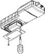
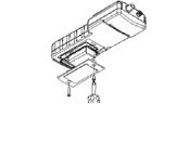
BATTERY INSTALLATION
An initial display of “LOW BAT” on the LCD indicates approximately one hour of battery life for unit operation within specifications. Replace battery when “LOW BAT” appears on the LCD.
To replace battery, remove the two battery cover screws and the battery cover and o-ring. Replace the 9V battery. Replace the battery cover and o-ring (be sure to align the o-ring correctly to prevent a bad
seal) and fasten the two battery cover screws for the splashresistant feature.
Figure 1.
Battery Installation
THE KEYPAD
1. : Turns the unit on or off.
2.MODE: In normal operation, toggles display between Dissolved Oxygen in % air saturation and Dissolved Oxygen in ppm (mg/L). In Calibration mode, exits current calibration and displays the next calibration parameter.
3.CAL: In normal operation, changes the mode from Normal to Calibration. See Calibration Set-up.
4. : In Calibration Set-up, press this key to save the current parameter to memory.
5.and Keys: Increases or decreases the display value as desired.
4
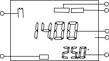
THE LCD DISPLAY
1.BAT: Low battery indicator.
2.CAL: Calibration mode indicator.
3.SAL ppt: Displays during calibration when user is prompted for the approximate salinity of the sample in parts per thousand (ppt).
4.mBar: Displays during calibration to prompt user for barometric pressure.
5.Main display for dissolved oxygen values.
6.%/ppm: Unit indicators.
7.ºC: Temperature display.
A |
|
|
|
|
|
|
|
|
3 |
|
BAT |
SAL ppt |
mBar |
4 |
1 |
|
|||
|
|
|
|
|
|
|
|
|
5 |
|
|
|
%ppm |
6 |
2 |
|
|
C |
7 |
|
CAL |
|
||
|
|
|
||
|
|
|
|
Figure2. LCD Display
OPERATIONAL PROCEDURES
Press  to turn the unit on or off. The instrument will perform a self-diagnostic test, during which an “ovEr” message may appear on the display. This is normal. After the warm up is complete the message will disappear. After the self-diagnostic test completes, the temperature displays in the lower right of the display, and the unit is ready for operation. Immerse the probe halfway into the sample solution. If possible, do not allow probe to touch any solid object in the solution. Allow no air bubbles around the probe. When the unit is not in use, turn it off to save battery life.
NOTE: During an oxygen measurement, the probe must be moved approximately 1/2 ft per second to overcome the inherent consumption of oxygen by the sensor. When using the 200BOD lab probe, however, simply use the probes self-stirring feature.
MEASUREMENT MODES
This unit provides three distinct measurements:
1.Temperature - Current solution temperature continually displays.
2.Dissolved Oxygen % - Measurement of oxygen in percent saturation.
3.Dissolved Oxygen ppm - Measurement of oxygen in ppm (mg/L).
Carefully observe the units displayed at the far side of the LCD to determine the desired mode.
CALIBRATION SET-UP
Requirements
1.The approximate pressure (in millibars [mBar]) of the region to be measured for dissolved oxygen.
2.The approximate salinity of the water to be analyzed. Fresh water has an approximate salinity of zero. Seawater has an approximate salinity of 35 parts per thousand (ppt).
3.For highest accuracy, complete all calibrations at a temperature as close as possible to the sample temperature.
5
Procedure
1.For the field probe, place 5-6 drops of clean water (tap, distilled, or deionized) into the sponge inside the calibration bottle. Turn the bottle over and allow any excess water to drain out of the bottle. The wet sponge creates a 100% water-saturated air environment for the probe, which is ideal for calibration, transport, and storage of the Model DO200 probe. For calibration, the probe remains in a water saturated air atmosphere and is not submersed.
For the lab probe, simply use the same bottle the probe is stored in with approximately 1 inch of water in the bottom. This creates a 100% water-saturated air environment for the probe, which is ideal for calibration and storage of the Model 200-BOD probe. For calibration, the probe remains in a water saturated air atmosphere and is not submersed.
2.For the field probe, slide it into the calibration bottle. Be sure the membrane does not touch the sponge.
3.Turn on the DO200 by pressing  . Wait 10 to 15 minutes for the dissolved oxygen and temperature readings to stabilize.
4.Press CAL.
5. The LCD prompts for the local pressure in mBar. Use the and keys to increase or decrease the pressure value respectively. See the section titled ‘Conversions’ to convert barometric pressure units to mBars.
6.When the proper pressure displays, press  once to view the calibration value in the lower right of the display. Once the value in the main display stabilizes, press
  again to move to the salinity compensation procedure.
7. The display prompts for the approximate salinity of the water to be analyzed. Use the andkeys to increase or decrease the salinity compensation value to the value of your sample (between 0 to 40 parts per thousand [ppt]). When the correct salinity displays, press  .
.
8.The unit holds calibration even if it is powered off. However, it is recommended to check calibration with each use and recalibrate as necessary to prevent drift. Dissolved oxygen readings are only as good as the calibration.
PROBE MAINTENANCE
To clean the probes, use the YSI Probe Reconditioning kit (part number 5238) for the field probe. For the lab probe, use the sanding disc included in the 5908 membrane kit and follow the cleaning instructions outlined in the 200-BOD probe manual in regards to sanding. In addition to the Reconditioning Kit and sanding disc with your 5908 membrane kit, you may try a chemical cleaning. To clean the electrodes chemically, perform an ammonium hydroxide soak.
1.Remove membrane cap and rinse the probe with clean water (tap, distilled, or deionized).
2.Turn unit off, or disconnect probe.
3.Obtain either:
•14 % lab strength ammonium hydroxide and soak for 2-3 minutes
•3% household cleaning strength ammonia and soak overnight (8-12 hours)
4.Rinse ammonium hydroxide/ammonia from probe.
5.Use sandpaper (400 grit wet/dry, supplied with 5238 kit and with the 5908 membrane kit) to buff (wet sand) excess deposits from probe.
6.Install a new membrane cap.
Never use chemicals or abrasives not recommended by YSI.
6

TROUBLESHOOTING
Main Display reads: |
Possible Solutions: |
|
• Check membrane and electrolyte solution. |
“ovEr” or “undr” |
• Clean anode and cathode. |
|
• Return product for service. |
Secondary Display reads: |
Possible Solutions: |
|
“undr” |
• Heat the sample to above –6.0 °C |
|
• Return product for service. |
||
|
||
“ovEr” |
• Cool sample to below 46.0 °C |
|
• Return product for service. |
||
|
SPECIFICATIONS
|
Display |
|
Range |
|
|
Accuracy |
Resolution |
|
|
Dissolved O2 |
|
0 to 20.00 ppm (mg/L) |
|
±2 % of the reading or ±2% air |
0.01 mg/L |
||
|
(ppm or mg/L) |
|
|
|
|
|
saturation, whichever is greater |
|
|
Dissolved O2 |
|
0 to 200.0 % |
|
|
±2% of the reading or ±0.2 ppm, |
0.1 % |
|
|
% air-sat |
|
|
|
|
|
whichever is greater. |
|
|
Temperature °C |
|
-6.0 to 46.0 °C |
|
±0.3 °C ±1 digit |
0.1 °C |
||
|
|
|
21 to 115 °F |
|
|
|
|
|
|
|
|
|
|
|
|||
|
Pressure Compensation |
|
600 to 1100 mBar (450 to 825 mmHg) |
|
||||
|
Salinity Compensation |
|
From 0.0 to 40.0 ppt |
|
||||
|
ATC Probe |
|
|
|
Thermistor, 10KΩ, at 25°C |
|
||
|
Calibration Backup |
|
Yes |
|
|
|||
|
Audio Feedback |
|
Yes, on all keys |
|
||||
|
Power Source |
|
|
|
One 9V battery |
|
||
|
Operating Temperature |
|
0 to 50°C (32 to 122 °F) |
|
||||
|
Instrument Casing |
|
Splash-resistant IP 65 |
|
||||
|
Weight (with battery) |
|
350 grams (.75 lbs) |
|
||||
|
Dimensions (L x W x D) |
|
186 mm x 70 mm x 37 mm (7.3 in x 2.8 in x 1.5 in) |
|||||
|
CONVERSIONS |
|
|
|
|
|||
|
|
|
|
|
|
|
||
|
To Convert: |
|
|
|
Multiply by: |
|
||
|
Inches of Hg to mBar |
|
33.864 |
|
|
|
||
|
Inches of Hg to mmHg |
|
25.4 |
|
|
|
||
|
mmHg to mBar |
|
|
|
1.333 |
|
|
|
|
RECOMMENDED SPARE PARTS LIST |
|
||||||
|
|
|
|
|
|
|
DESCRIPTION |
|
|
PART # |
|
|
|
|
|
|
|
|
200-4 |
4 meter (approx. 13 feet) probe and cable assembly |
|
|||||
|
200-10 |
10 meter (approx. 33 feet) probe and cable assembly |
|
|||||
|
200-BOD |
Self-stirring BOD lab probe and cable assembly with power supply |
||||||
|
485 |
DO carrying case, soft sided |
|
|
||||
|
280 |
DO carrying case, hard sided |
|
|
||||
|
5908 |
Membrane kit, 1.25 mil PE (605306), six cap membranes and KCl solution |
||||||
|
480 |
Instrument carrying case, soft |
|
|
||||
Item #605368 • Drawing #A605368
Revision E • March 2008
For the latest version of this manual, visit www.ysiecosense.com
7
GARANTIE
L’appareil EcoSense® DO200 est garanti pour une période d’un an, à compter de la date d’achat par l’utilisateur final, contre tout défaut matériel et de fabrication. Les sondes et les câbles de DO200 sont garantis pour une période d’un an, à compter de la date d’achat par l’utilisateur final, contre tout défaut matériel et de fabrication. Pendant la période de garantie, YSI s’engage à réparer ou à remplacer, gratuitement et à sa discrétion, tout produit qu’YSI peut établir comme étant couvert par la garantie.
Pour faire valoir cette garantie, écrivez ou appelez votre représentant YSI ou contactez le Service clientèle d’YSI à Yellow Springs, Ohio, États-Unis. Envoyez le produit et son justificatif d’achat en port payé au Centre de service homologué sélectionné par YSI. La réparation ou le remplacement seront effectués et le produit vous sera retourné en port payé. Les produits réparés ou remplacés sont garantis jusqu’à expiration de la période de garantie originale ou au moins 90 jours à compter de la date de réparation ou de remplacement.
Limitation de garantie
Cette garantie ne s’applique pas aux produits YSI endommagés ou présentant des dysfonctionnements pour les raisons suivantes : (i) installation, exploitation ou utilisation du produit d’une façon non conforme aux instructions écrites d’YSI ; (ii) abus ou mésusage du produit ; (iii) manquement à l’entretien du produit conformément aux instructions écrites d’YSI ou aux procédures industrielles normales ; (iv) réparation non conforme du produit ; (v) utilisation par vous de pièces ou de composants défectueux ou non conformes lors de l’entretien ou de la réparation du produit ; ou, (vi) modification du produit d’une façon non expressément autorisée par YSI.
CETTE GARANTIE REMPLACE TOUTES LES AUTRES GARANTIES, EXPRESSES OU INDUITES, Y COMPRIS LES GARANTIES DE COMMERCIABILITÉ OU D’ADAPTATION À UN USAGE PARTICULIER. LA RESPONSABILITÉ D’YSI SELON LES TERMES DE CETTE GARANTIE SE LIMITE À LA RÉPARATION OU AU REMPLACEMENT DU PRODUIT, CONSTITUANT VOTRE SEUL ET UNIQUE RECOURS POUR TOUT PRODUIT DÉFECTUEUX COUVERT PAR CETTE GARANTIE. YSI NE POURRA EN AUCUN CAS ÊTRE TENU RESPONSABLE DE DOMMAGES SPÉCIAUX, INDIRECTS, ACCIDENTELS OU CONSÉCUTIFS RÉSULTANT DE L’UTILISATION DE TOUT PRODUIT DÉFECTUEUX COUVERT PAR CETTE GARANTIE.
COMMENT NOUS CONTACTER
YSI Inc. • 1725 Brannum Lane • Yellow Springs OH, 45387, États-Unis 800-897-4151 • 937-767-7241 • Télécopie : 937-767-1058
E-mail : ecosense@ysi.com • Site Web : www.ysiecosense.com
1
TABLE DES MATIÈRES |
|
|
GARANTIE ......................................... |
ERROR! BOOKMARK NOT DEFINED. |
|
COMMENT NOUS CONTACTER......ERROR! BOOKMARK NOT DEFINED. |
||
INFORMATIONS GÉNÉRALES...................................................................... |
|
3 |
INSPECTION INITIALE................................................................................... |
|
3 |
PRÉCAUTIONS .............................................................................................. |
|
3 |
Boîtier........................................................................................................ |
|
3 |
Sonde........................................................................................................ |
|
3 |
PRÉPARATION DE LA SONDE ..................................................................... |
|
4 |
INSTALLATION DE LA PILE .......................................................................... |
|
4 |
CLAVIER ......................................................................................................... |
|
4 |
ÉCRAN À CRISTAUX LIQUIDES ................................................................... |
|
5 |
PROCÉDURES D’UTILISATION .................................................................... |
|
5 |
MODES DE MESURE..................................................................................... |
|
5 |
CONFIGURATION DE L’ÉTALONNAGE........................................................ |
5 |
|
Exigences préalables................................................................................ |
|
5 |
Procédure ................................................................................................. |
|
6 |
ENTRETIEN DE LA SONDE........................................................................... |
|
6 |
DÉPANNAGE.................................................................................................. |
|
7 |
SPÉCIFICATIONS .......................................................................................... |
|
7 |
CONVERSIONS.............................................................................................. |
|
7 |
LISTE DES PIÈCES DÉTACHÉES RECOMMANDÉES ................................ |
7 |
|
2
INFORMATIONS GÉNÉRALES
L’ DO200 est un des trois instruments de la ligne de produits EcoSense® de YSI. L’ DO200 est un outil de précision mesurant l’oxygène dissous en pourcentage, ppm (mg/l) ainsi que sa température. Un microprocesseur incorporé stocke, calcule et compense tous les paramètres relatifs aux déterminations liées à l’oxygène dissous, y compris les caractéristiques de température des électrodes de détection de l’oxygène dissous.
L’appareil est doté d’un boîtier résistant aux éclaboussures, conforme à la norme IP65. Les touches mécaniques sont très fiables et fournissent une réaction tactile et sonore. Cet appareil utilise une pile de 9 V. Aucun réétalonnage n’est nécessaire lorsque l’alimentation électrique est rétablie.
L’avant de l’appareil dispose d’un écran à cristaux liquides affichant simultanément le pourcentage, les mg/l et la température de l’oxygène dissous, ainsi que les invites destinées à l’utilisateur et les indicateurs de mode. L’appareil émet des invites destinées à l’utilisateur lors des procédures d’étalonnage et de mesure.
Le modèle de sonde de terrain et de laboratoire DO200 utilise une électrode polarographique disposant de capuchons à membrane vissables. Les sondes de terrain 200-4 et 200-10 sont équipées d’une sonde de température incorporée permettant la compensation automatique de la température, ainsi que d’un corps en acier inoxydable qui en augmente la masse. La sonde de laboratoire 200-BOD est équipée d’un bloc d’alimentation électrique et comporte des électrodes remplaçables auto-agitées.
Parmi les autres caractéristiques, on notera la longue durée de vie des piles et une élimination du bruit élevée de 50/60 Hz c.a. Cet appareil est convivial et particulièrement souple dans les applications sur le terrain, industrielles et en laboratoire.
INSPECTION INITIALE
Déballez soigneusement l’appareil et les accessoires et vérifiez qu’ils n’ont pas été endommagés lors de l’expédition. Comparez les pièces reçues aux matériaux répertoriés dans le bordereau d’emballage. Notifiez immédiatement YSI s’il s’avère que des pièces sont endommagées ou manquantes. Mettez de côté les matériaux d’emballage jusqu’à ce que le fonctionnement correct de l’appareil soit confirmé.
PRÉCAUTIONS
Boîtier
Bien que le modèle DO200 soit abrité dans un boîtier résistant aux éclaboussures conforme à la norme IP65, ne l’utilisez PAS sous l’eau, car son connecteur n’est pas étanche. Le boîtier résistant aux éclaboussures prévient les dommages permanents si l’appareil est accidentellement éclaboussé par des solutions non corrosives. En cas de submersion, prenez immédiatement les mesures suivantes :
1.Séchez le connecteur, le cas échéant, et remplacez la sonde d’oxygène dissous. Rincez soigneusement l’appareil avec de l’eau distillée. Après le rinçage et le séchage, inspectez et nettoyez les connecteurs en vue d’éliminer tout contaminant pouvant affecter les connexions de la sonde.
2.Attendez que l’appareil et la sonde soient parfaitement secs avant de reprendre les opérations.
3.Si l’appareil ne fonctionne pas correctement après les étapes 1 et 2, appelez YSI en vue d’une réparation ou d’un remplacement éventuels (voir la Garantie).
Les sondes (de terrain et de laboratoire)
1.Les membranes durent plus longtemps si elles sont correctement installées et entretenues régulièrement. Des membranes endommagées ou sales et des grosses bulles dans le réservoir d’électrolyte peuvent entraîner des lectures incohérentes. Si les lectures sont instables ou la membrane endommagée, remplacez le capuchon à membrane et la solution de la sonde à oxygène (également appelée « Électrolyte de sondage d’oxygènométrie », chlorure de potassium ou solution KCl). Les intervalles de remplacement sont habituellement de 4 à 8 semaines, bien qu’ils puissent se prolonger s’ils sont conservés en
3
bon état de propreté. Les milieux particulièrement difficiles, tels que les eaux usées, peuvent exiger que la membrane soit remplacée toutes les 2 à 4 semaines. Des lectures instables peuvent avoir lieu si le capuchon à membrane est recouvert d’organismes consommant ou évoluant dans l’oxygène, tels que des bactéries ou des algues.
2.Le chlore, l’anhydride sulfureux, le monoxyde d’azote et l’oxyde nitreux peuvent affecter les lectures en se comportant comme de l’oxygène au niveau de la sonde.
3.Évitez les produits pouvant endommager les matériaux de la sonde, tels que l’acide concentré et les solvants puissants et caustiques. Les matériaux de la sonde comportent de l’acier inoxydable, de l’adhésif époxyde et du plastique ABS.
4.Gardez la cathode dorée de la sonde en bon état de propreté et texturée (lorsqu’elle est correctement entretenue, elle présente un fini mat). Si elle se ternit (après être entrée en contact avec certains gaz) ou présente un aspect argenté (en raison d’une utilisation prolongée avec une membrane lâche ou plissée), nettoyez-la en suivant les instructions de la section « Entretien de la sonde ».
5.Pour éviter que la membrane et l’électrode se dessèchent, stockez la sonde de terrain dans la bouteille d’étalonnage avec l’éponge humide et la sonde de laboratoire dans un flacon BOD avec 2,5 cm (1 po) d’eau pour les conserver dans un milieu saturé.
PRÉPARATION DE LA SONDE
La sonde DO200 est fournie avec une membrane protectrice sèche. Pour installer un nouveau capuchon à membrane sur la sonde :
1.Dévissez le capuchon à membrane de la sonde et jetez-le.
2.Remplissez un nouveau capuchon de solution de sondage d’oxygénométrie. Effectuez la préparation conformément aux instructions de la bouteille de solution.
3.Enfilez le capuchon à membrane rempli sur le capteur.
4.Laissez l’ensemble se réchauffer suffisamment longtemps lors de la première utilisation (10 à 15 minutes). Il se peut que le message « ovEr » s’affiche pendant ce temps sur l’écran. Cette condition est normale. Le message disparaîtra une fois le chauffage terminé.
INSTALLATION DE LA PILE
Lorsque l’écran à cristaux liquides affiche pour la première fois « LOW BAT », il reste environ une heure de fonctionnement sur pile selon les spécifications. Remplacez la pile lorsque l’indication « LOW BAT » s’affiche sur l’écran.
Pour remplacer la pile, enlevez les deux vis du compartiment ainsi que le couvercle et le joint torique. Remplacez la pile de 9 V. Replacez le couvercle et le joint torique (veillez à aligner le joint
correctement afin d’assurer une bonne étanchéité) et revissez les deux vis du compartiment pour conserver une bonne résistance aux éclaboussures.
Figure 1. Installation de la pile
CLAVIER
1. : Met l’appareil hors ou sous tension.
2.MODE : En fonctionnement normal, bascule l’affichage entre la mesure de l’oxygène dissous exprimée en pourcentage de saturation de l’air ou exprimée en ppm (mg/l). En mode d’étalonnage, quitte l’étalonnage actuel et affiche le paramètre d’étalonnage suivant.
3.CAL : En fonctionnement normal, passe du mode Normal au mode Étalonnage (Calibration). Voir la section Configuration de l’étalonnage.
4. : Lors de la configuration de l’étalonnage, appuyez sur cette touche pour enregistrer le paramètre actuel en mémoire.
5.Touches et : Augmentent ou diminuent la valeur affichée, comme voulu.
4
Loading...