


® |
YSI 9300 and 9500
Photometers
User Manual

® |
YSI 9300 and 9500
Direct-Read Photometers
User Manual
YSI, Inc.
1725 Brannum Lane Yellow Springs, OH 45387
Tel: 800-897-4151 (+1 937-767-7241) Fax: +1 937-767-1058 E-Mail: environmental@ysi.com
|
|
Y- PT 282 |
|
INDEX |
|
1 |
INTRODUCTION .............................................................................................................. |
1 |
|
Features and Technical Specification ................................................................................ |
3 |
2 |
OPERATING PRINCIPLE ................................................................................................... |
4 |
|
Powering the Photometer .................................................................................................. |
4 |
|
Replacing the Batteries...................................................................................................... |
5 |
|
Power Supply (Model 9500 only) ....................................................................................... |
5 |
3 |
GENERAL PHOTOMETER OPERATION ............................................................................... |
6 |
|
Operating Modes ............................................................................................................... |
6 |
|
System - Quick Start.......................................................................................................... |
6 |
|
System - Full Options ........................................................................................................ |
7 |
|
View Log (9500 Only) ........................................................................................................ |
7 |
|
Back Light.......................................................................................................................... |
7 |
|
Language Options ............................................................................................................. |
7 |
|
Units.................................................................................................................................. |
8 |
|
Sample Number (9500 Only) ............................................................................................. |
8 |
|
Sample Number Increment (9500 Only)............................................................................. |
8 |
|
Dilution Factor (9500 Only) ................................................................................................ |
8 |
|
Date and Time (9500 Only)................................................................................................ |
8 |
|
Date Format (9500 Only) ................................................................................................... |
8 |
|
Battery Level ..................................................................................................................... |
8 |
|
Locking System Mode Settings (9500 Only) ...................................................................... |
9 |
|
Rounding (9500 Only)........................................................................................................ |
9 |
|
Time-Out (9500 Only)........................................................................................................ |
9 |
|
Edit User Defined Tests (9500 Only).................................................................................. |
9 |
|
USB (9500 Only) ............................................................................................................. |
10 |
4 INTERFACE CONNECTIONS AND DATA MEMORY (9500 ONLY) ......................................... |
11 |
|
5 |
TAKING PHOTOMETER READINGS................................................................................... |
12 |
|
Program Numbers and Test Instructions.......................................................................... |
12 |
|
Sample Dilution (9500 Only) ............................................................................................ |
12 |
|
Blank and Sample Tubes................................................................................................. |
12 |
|
Light Cap......................................................................................................................... |
13 |
|
Getting the Best Results .................................................................................................. |
13 |
|
Taking Test Readings...................................................................................................... |
13 |
|
Continuation Tests (Certain Tests Only) .......................................................................... |
16 |
|
Favorite Tests List ........................................................................................................... |
16 |
|
Expressing Different Chemical Forms.............................................................................. |
16 |
|
Reading in Transmittance and Absorbance ..................................................................... |
17 |
|
Timer............................................................................................................................... |
17 |
|
User Defined Tests (9500 Only)....................................................................................... |
17 |
6 |
CARE AND MAINTENANCE .............................................................................................. |
20 |
|
Cleaning the Optics ......................................................................................................... |
20 |
|
Service Requirement ....................................................................................................... |
20 |
|
Error Messages ............................................................................................................... |
20 |
|
Photometer Up-Grade (9500 only)................................................................................... |
21 |
|
Computer Controlled Operation (9500 Only).................................................................... |
21 |
|
Warranty.......................................................................................................................... |
21 |
|
Limitation of Warranty...................................................................................................... |
22 |
|
Contact Information ......................................................................................................... |
22 |
1 INTRODUCTION
The YSI 9300 and 9500 direct-read photometers are designed to give long and trouble-free operation. To ensure the best results, please read this manual carefully and follow the procedures recommended. This manual covers both the 9300 and 9500 photometers. Therefore, some of the information only pertains to the 9500 as is noted in the appropriate sections.
The Photometers feature digital electronics and built-in filters. It is lightweight and portable for field or laboratory use. The instruments are rugged, durable and IP-67 rated. Additionally, the photometers are direct-reading, have automatic blank setting, automatic wavelength selection, and automatic power cut-off.
The following pages describe the use of the photometers, and give instructions for the wide range of water tests which can be performed using these instruments.
Keep the photometer clean and in good working order by adhering to the following recommendations:
Do not pour out samples or prepare the tests directly over the instrument.
Always cap the test tubes before inserting into the instrument for readings.
Wipe test tubes with a clean tissue to remove drips or condensation before placing in the photometer.
Do not leave tubes standing in the photometer test chamber. Remove the tubes immediately after each test.
Immediately wipe up any drips or spills on the instrument or in the test chamber with a clean tissue.
Keep the instrument clean. Clean the test chamber regularly using a moistened tissue or cotton ball.
Keep the instrument away from all chemicals and cleaning materials.
Keep the instrument in a clean, dry place when it is not in use. Keep it on a clean, dry bench away from chemicals, place it in a storage cupboard or keep it in a carrying case.
Keep the carrying case in a clean, dry condition. Make sure that the carrying case is dry before the case is closed up and the instrument is put away.
1
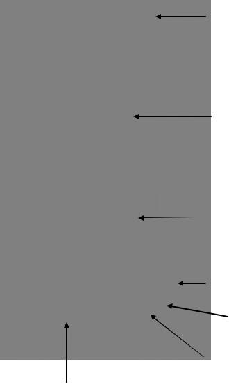
Instrument Layout
USB Interface (9500 only)
Multi-Size Cell
Graphic Display
On/Off Key
Scroll and Selection Keys
OK (Enter) Key
Test and
Number Keys
2
Features and Technical Specification
Application |
For application in general water testing using Palintest |
|
tablet reagent systems and Palintest Tubetests reagents. |
Instrument Type |
Single-beam colorimeter with built-in colour filters and pre- |
|
programmed test calibrations. |
Peak Wavelengths |
445 5nm, 495 5nm, 555 5nm, 570 5nm, 605 |
|
5nm and 655 5nm |
Range |
1 - 100%T |
Accuracy |
1%T |
Display |
Large graphic display with option of backlight. |
Language |
Test identification and prompts in English, French, |
|
German, Spanish and Italian. |
Timer |
Clock and timer feature to log test results and audible |
|
alarm for timing test procedure. |
Units |
Direct-reading of test results in mg/l, ppm, g/l or molar |
|
units (mmol/l or µmol/l). |
User Selectable Options |
10 digit sample number entry, dilution factor, time/date, |
|
date format, system lock and rounding of results. |
Date Format |
Date format selectable as day/month/year or month/day/ |
|
year. |
Zeroing |
Automatic zeroing on blank tube and hold blank facility for |
|
series of tests. Continuation test facility without the need |
|
for reblanking. |
Internal Memory |
Stores 500 previous readings with option to view logged |
|
results on screen, or download to computer. |
USB Interface |
USB 1.1 full-speed, bus-powered device. Software selectable |
|
between either emulation of a removable hard-drive or |
|
emulation of a serial device connected via a virtual COM port. |
Power |
3 x 1.5V ‘AA’ alkaline batteries or via USB interface. Power |
|
management system with variable length auto switch-off |
|
or 'continuous' operation. |
Size |
250 x 150 x 70 mm |
Weight |
985 g (2.1 lbs) |
Test Tubes |
For tablet reagents - 10 ml glass test tubes, 20 mm OD |
|
(YPT 595). |
Cell Holder |
Multi-size tube holder accepts test tubes from 12 – |
|
20 mm OD and centres the tube for optimum optical |
|
performance. |
|
3 |
2 OPERATING PRINCIPLE
The YSI photometers are instruments that measure color intensity. Light is passed through a test tube containing the sample solution, and then through a colored filter onto a photodetector. Filters have been chosen so that light of a specific wavelength is selected. When the solution is completely colorless, all of the light passes through the sample. With colored samples, light is absorbed and the light which passes through the sample is proportionately reduced.
In the following test procedures, the photometer is used to measure the color which is produced when chemical reagents are reacted with the water sample. In these tests, the color intensity produced is proportional to the concentration of the parameter being tested.
The photometer is pre-programmed with calibrations for each test parameter. Different test procedures are carried out at different wavelengths to optimize the sensitivity of each test. The required wavelength is selected automatically by the instrument.
The calibrations are accessed by entering a unique program number at the start of each test procedure. This enables the instrument to select the appropriate wavelength filter automatically and allows the photodiode response to be converted to a concentration reading. The instrument thus displays a directreading of the test result.
The photometer is ideally suited for general analytical applications. The instrument can be used as a laboratory or field photometer with user-generated calibration graphs for standard analytical methods or for comparison of colored solutions.
For general analytical applications, Transmittance (test program 0), or Absorbance (test program 1) can be chosen.
Powering the Photometer
The Photometer is powered by (3) AAA batteries. The photometer features a battery indicator – see ‘System Mode’ functions. A minimum voltage of 3.0V is needed to operate the photometer. As a power-saving measure, in normal use, both the 9300 and 9500 photometers automatically switch off five minutes after the last key is pressed. The switch off period may be adjusted for the 9500 in the System mode.
In addition to the above feature, a battery-warning message will appear automatically on the display when the battery voltage becomes low. The batteries should be replaced as soon as possible after the warning message appears. Stored data in the instrument memory will not be lost during battery replacement.
4
Replacing the Batteries
The battery compartment in the base of the instrument is secured by four screws. To replace the batteries, remove the cover and install the batteries, observing the correct polarity as indicated. Use 3 x 1.5V 'AA’ alkaline batteries or equivalent. To avoid corrosion damage through leakage, remove batteries from the instrument if it is to be stored or left unused for a long period of time (> 30 days).
Power Supply (Model 9500 only)
The 9500 photometer can be powered either from alkaline batteries or via the USB socket. To use mains power, the instrument is connected using the USB Connection Cable (YPT 284) plugged to the Mains Adapter (YPT283). Alternatively, the USB connection cable can be plugged into a computer to power the 9500 from the computer.
5
3 GENERAL PHOTOMETER OPERATION
The photometer is controlled by a simple intuitive menu system:
The highlight indicates the active line or section of the screen
The and keys move the highlight through the menu choices
The and keys allow selection of options
The flashing cursor in the ‘Options’ menu at the bottom of the screen indicates the action which will occur if the [OK] button is pressed.
Operating Modes
The photometer has two distinct operating modes - the PHOTOMETER mode and the SYSTEM mode.
The PHOTOMETER mode is the normal operating mode for taking photometer readings. This mode is engaged automatically when the instrument is turned on by pressing the  key.
key.
As a power-saving measure, in normal use, both the 9300 and 9500 photometers automatically switch off five minutes after the last key is pressed. This may be adjusted for the 9500 in the System mode.
The SYSTEM mode is used to set the system options. This mode is engaged when the photometer is turned on using the  key and then selecting 'System' using the and keys and pressing [OK].
Scroll through the menu box to view all the options available.
System - Quick Start
When the instrument is first used, the SYSTEM mode should be used to set the preferred operating options:
Use the and keys to scroll through the features.
Use the and keys to select the options.
Press [OK] to accept the selections and return to PHOTOMETER mode.
Select the desired language from English, French, German, Spanish or Italian.
Select the desired display units from mg/l, ppm, mmol/l, µmol/l and g/l.
Set the sample number option to ‘On’ to allow the entry of a sample number during normal photometer operation (model 9500 only).
Set the sample increment option to ‘On’ to automatically increase the sample number (model 9500 only).
6
Set the dilution factor to ‘On’ or ‘Off’. If the dilution factor option is set to ‘On’, the instrument will allow the entry of a numerical factor which will be used in the calculation of the result displayed on the instrument (model 9500 only).
Select the preferred date format. The date may be shown in either Day/ Month/Year or Month/Day/Year (9500 only).
To change the date and time, select the date and time line then key in
correct setting using the numeric keys. To correct an error, use the  keys to move the cursor then key in the correct data (9500 only).
System - Full Options
The Photometer features a wide range of options which may be explored at leisure to get the best results from the instrument. An explanation of the application of these options is as follows:
View Log (9500 Only)
The 9500 photometer has an internal memory which can hold up to 500 test results. Once the memory is full, each new result overwrites the oldest entry.
Select ‘View Log’ to view stored results on screen. The  used to scroll through the list of stored results. The ‘Options’ menu offers several choices.
Select ‘Clear’ to empty the memory. Confirmation is requested to avoid accidentally erasing the data. Select ‘Exit’ to return to SYSTEM mode. Select ‘Download’ to transmit stored data to a PC. This option only appears if the USB mode is set to ‘COM Port’. Refer to ‘Interface Connection and Data Memory’ for further information.
Back Light
The graphic display features a backlight to enhance the display contrast. This may be switched off to conserve power when working on battery power.
Language Options
The photometer can be operated in a number of different languages. When a particular language is selected, the test names and operating commands will appear in that language. Certain tests and unit options are provided in accordance with the conventions of particular countries and are only available when the photometer is switched to the language that particular country.
7
Units
The photometer offers the choice of result expressed in mg/l, ppm, mmol/l, µmol and g/l.
Sample Number (9500 Only)
A unique number may be associated with each result record to identify it in the log. If Sample Number ‘On’ is selected, the user is offered the choice of entering a number of up to 10 digits for each sample reading. If this function is set to ‘Off’, a sample number is automatically allocated.
Sample Number Increment (9500 Only)
The sample number increment option may be used to determine whether the instrument does or does not automatically increment the sample number after each test. Incrementation of the sample number may be used when the instrument is used for carrying out a series of similar tests. Alternatively it may be preferable not to increment the number if typical use involves carrying out a number of different tests on the same sample.
Dilution Factor (9500 Only)
When samples are out of range for the test, a dilution procedure may be used. If the dilution factor option is set to ‘On’, the instrument will allow entry of a numerical factor which will be used in the calculation of the result displayed and stored in the log.
Date and Time (9500 Only)
The instrument records the date and time of each reading taken and associates this with the data record in the log. To correct the date and time on the internal clock, select the date and time display line.
Date Format (9500 Only)
The option of day/month/year or month/day/year date format is available.
Battery Level
A battery level indicator shows the power available. At least 3.0V is required for successful operation of the instrument.
8
Locking System Mode Settings (9500 Only)
It is possible to 'lock’ the system settings so that these cannot be tampered with or altered accidentally during use. This is important, for example, where it is necessary to verify that tests have actually been carried out at a particular time or date, or where procedures always require the use of a sample number or dilution factor.
The instructions for locking the settings are not included in this manual; these are provided to photometer owners or system administrators on formal request to YSI’s Technical Support department (environmental@ysi.com).
Rounding (9500 Only)
In the normal default setting, the photometer will round test results appropriately for the resolution of the test. The rounding applied differs for each parameter depending on the shape of the calibration curve. This ensures the optimum precision and accuracy of each test procedure. For normal purposes it is strongly recommended that the instrument be left in the default setting.
However, for certain analytical applications, it may be useful to switch off the rounding to display the result in unrounded form. This may be the case, for example, when carrying out statistical evaluations of test methods where it is necessary to use the data in calculation of standard deviation or distribution data.
Time-Out (9500 Only)
As a power-saving measure, in normal use, both the 9300 and 9500 photometers automatically switch off five minutes after the last key is pressed.
The 9500 photometer may be switched to ‘Long’ time-out which allows 15 minutes before shut-down or ‘Off’ which allows continuous use. This is particularly useful when powering the instrument through the USB interface.
Edit User Defined Tests (9500 Only)
Users may wish to develop their own test methods and store calibrations on the photometer. The 9500 has the facility to store up to 30 user-defined calibrations. See ‘User Defined Tests’ below for full instructions.
9
USB (9500 Only)
The USB interface allows communication between the instrument and a PC. There is a choice of two operating modes – Hard Drive and COM Port.
In Hard Drive mode, the instrument appears as a removable hard drive when connected to a PC. No additional software is required on computers running Windows 2000, ME or XP. A driver to use this option with Windows 98SE is available from YSI Technical Support Department (environmental@ysi.com).
In COM Port mode, the instrument behaves as if connected to the PC serial port via RS232. In this mode, the PC requires installation of a USB virtual COM Port driver, available from YSI Technical Support Department (environmental@ysi.com).
See the section on ‘Interface Connections and Data Memory’ below for full instructions.
10
4 INTERFACE CONNECTIONS AND DATA MEMORY (9500 ONLY)
Stored data can be accessed by recall to the instrument display (see ‘View Log’). Alternatively, data can be accessed using a PC:
Connect the instrument to the computer via the USB port, using any suitable USB cable, ie YPT 746
Turn the instrument ON and select SYSTEM mode from the ‘Options’ menu
Scroll to ‘USB’ and select either ‘Hard Drive’ or ‘COM Port’.
‘Hard Drive’ – Once this option is selected, simply turning the instrument ON while it is connected to a PC will cause an extra hard drive containing the instrument files to appear on the PC. The log of test results is in text file:
‘9500_LOG.txt’. The other files shown on screen contain calibration and operating systems for use when upgrading the instrument and should not be accessed.
The log file can be copied from the instrument by dragging between windows. Once copied, the file can be opened with many text editors, word processors or spreadsheet programs.
Note: Deleting this file from the instrument’s hard drive will clear the data from the instrument memory.
‘COM Port’ – Once this option is selected, data can be downloaded from the instrument to the PC:
Open the ‘Virtual COM Port – HyperTerminal’ window on the computer
In the instrument SYSTEM mode, scroll to ‘View Log’ and select ‘Download’.
The data from the log will appear on the PC screen and can be transferred to other PC applications or printed.
‘Unplugged’ – Note that the ‘Hard Drive’ or ‘Com Port’ may only be selected while the instrument is being powered via its USB port. If the instrument is running on batteries and is not connected to either a PC or a YPT783 external power supply, an ‘Unplugged’ message will be displayed instead of either ‘Hard Drive’ or ‘COM Port’.
11
5 TAKING PHOTOMETER READINGS
The photometer is very simple to use. Screen prompts guide the user towards the test result. The following sections describe how to get the best results from the instrument.
Program Numbers and Test Instructions
Each test is identified by a separate program number or named key. Program numbers are shown in the test instruction sheets supplied in this manual. For some tests, a choice of different programs is offered in order to get the result in different forms (for example, for Nitrate - NO3 or Nitrate Nitrogen - NO3-N).
In certain tests, such as free chlorine and total chlorine, the test can be continued to a further stage. This is allowed for in the programming of the photometer. In these tests, once the result of the first stage is obtained, the
‘Follow-On’ option may be selected to progress the test to the next test stage or stages. The result will be calculated automatically.
These continuation programs have their own program number for reference purposes although direct access to these programs may be restricted.
Sample Dilution (9500 Only)
The photometer has a sample dilution option. This enables a factor to be entered when samples have been diluted to bring them within the measuring range of the test. For example, if a five times dilution of a sample has been made, then a dilution factor of x5 should be entered. The photometer will multiply the observed result by this factor so that the correct result for the original sample is displayed.
This option may be used in conjunction with the YSI Dilution Tube (YPT 512) which enables dilutions of x2, x3, x4, x5 and x10 to be made. Higher dilution factors may be entered but are subject to the limitation of the number of digits available of the result display for each test. When the display capabilities are exceeded, the symbol [xxx] will appear on the result display. The sample should not be diluted prior to carrying out a pH test, or a Transmittance or Absorbance reading.
Blank and Sample Tubes
A BLANK TUBE is needed each time the photometer is used. This enables the instrument to be set automatically and compensates for any inherent color in the test sample. It is important therefore to understand the meaning of the term ‘BLANK TUBE'.
12
The BLANK TUBE is a test tube filled only with the water being tested only. It is important to use the actual water to be tested to provide a true comparison for the test results.
The term 'SAMPLE TUBE' is used to describe the tube containing the water sample to which the reagents have been added in accordance with the appropriate test instructions. This tube is used to take the photometer reading.
Light Cap
A light cap is provided with the photometer. This cap fits over the test chamber and prevents stray light reaching the photodiode.
It is NOT necessary to use the light cap when using the photometer indoors or under shaded outdoor light. The light cap should be used when working outside in strong sunlight. The light cap is also recommended when carrying out turbidity-based tests such as the cyanuric acid test, under bright or variable lighting conditions. Test instructions indicate when the light cap should be used.
Getting the Best Results
Success in obtaining accurate and consistent test results will depend on the care with which test procedures are carried out. Always follow the test instructions carefully and observe the stated standing periods and temperature conditions where applicable.
Wipe test tubes free from condensation before placing in the photometer. Test tubes should always be kept in a clean condition. Wash and dry the test tubes carefully after use. Dirty tubes may be soaked in a mild detergent solution if necessary. Tubes which become stained or scratched should be discarded and replaced.
Taking Test Readings
Press  key. The instrument displays the ‘Choose a Test’ menu box, with the last test program used highlighted as the active line.
The cursor will flash on the [OK] symbol of the ‘options menu' at the bottom of the screen. Press [OK] to accept this program.
To choose a different test program, either use the and keys to scroll through the menu options, or use the numeric keys to enter the Phot number of the desired test. The four most recently used tests are listed at the top of the ‘Choose a Test’ screen for convenience. Press [OK] to accept the selected program.
13

If the sample number option is pre-selected, then the following display will appear, for example (9500 only):
Sam ple Num ber
1024

 O K
O K
Enter or confirm the sample number (up to 10 digits), then press [OK].
1If the dilution factor option is pre-selected, then the following display will appear (9500 only):
Dilution Factor
x 1

 O K
O K
Press [OK] to accept the default value (x1, no dilution), or key in new dilution factor then press [OK].
2 The following display will now appear:
P h o t 007
C hlorine-Free / 5
Insert B lank
OK |
Choos e a Te st |
|
Place a BLANK TUBE in the test chamber, then press [OK].
NOTE: The instrument is designed to hold the blank setting as long as the instrument is switched on. This stage will be omitted when further tests are being carried out. However, when changing to a test which requires a colored or reagent blank, or uses a tube of a different diameter, a new blank reading is required. The ‘Insert Blank’ prompt will be displayed automatically.
If the instrument is in used continuously, it is advisable to re-blank from time to time.
14

3The instrument will be set automatically. After a few seconds the following display will appear:
P h o t 007
C hlorine-Free / 5
Insert S am ple
OK |
Bla nk - Choose a Te st - Tim e |
|
Place SAMPLE TUBE in the test chamber, then press [OK].
4The instrument will take the reading and display the result as follows, for example:
Phot 007
Chlorine-Free / 5
1.00
mg/l Cl2
Choose a Test |
Read Blank Follow-On |
The following symbols indicate the result is out of test range: Result is higher than range: >>
Result is lower than range: <<
5The ‘options menu' offers the choice to:
‘Choose a Test’ - return to the menu of test programs and select another test
‘Read’ |
- |
read further sample tubes of the currently selected test |
‘Blank’ |
- |
re-blank the instrument |
‘Follow-On’ |
- |
carry out a continuation test if available. |
15

Continuation Tests (Certain Tests Only)
1Select ‘Follow-On’ and press [OK] while the result is displayed of the currently running test. The photometer applies the previously entered sample number and dilution factor, and the ‘Insert Sample’ screen will appear.
Place SAMPLE tube in the test chamber, then press [OK].
2The instrument will take the reading and calculate the result from the combination of readings (where appropriate). The result will be displayed as follows, for example:
Phot 008
Chlorine-Total / 5
1.50
mg/l Cl2
Choose a Test Read Blank |
Return |
3While the test result is displayed, similar options are available as at the end of a normal test program. In order to run more samples for the same parameters, select ‘Return’ from the ‘options menu' to take the program back to the start of the first stage of a multiple test procedure.
Note: some continuation test procedures involve a standing period. The photometer may switch off automatically during this time. To avoid the instrument switching off, set for continuous operation or use the timer function to time any standing period. See Timer section. The timer will over-ride the auto switch off function.
Favorite Tests List
The four most recently used tests are listed at the top of the 'Choose a Test' screen for convenience.
Expressing Different Chemical Forms
If the test result can be expressed in different chemical forms, the chemical symbol will have flashing and to indicate this. Use the and keys to step through the options available.
Note that the log stores the result in the primary form.
16
Reading in Transmittance and Absorbance
When taking readings in Transmittance or Absorbance mode, use the and keys to step through the wavelengths until the required wavelength is reached.
Timer
The photometer features a countdown timer with alarm as an aid to carrying out test procedures. The timer can be accessed at any time by selecting
‘Timer’ from the ‘Options’ menu.
The following display will appear:
T im er
00:00
EXIT
Key in the time required in minutes and seconds using the numerical keys, then press [OK] to start the timer. The maximum time is 29 minutes and 59 seconds. Use the and keys to reposition the cursor and re-enter the time if it is keyed in incorrectly.
The timer will count down, giving an audible alarm at the end of the timed period. Press [OK] to stop the alarm.
During the timer countdown period, an ‘Options’ menu is available :
Stop |
- used to abort the timing operation or to stop the alarm at |
|
the end of the timed period |
Exit |
- used to return to the program screen to take readings. The |
|
timer will continue to run and give an audible alarm at the |
|
end of the period. |
Exit and Read |
- used to return to the program screen with the timer counting |
|
down on screen. The instrument will automatically take a |
|
reading at the end of the timed period and no alarm will |
|
sound. |
User Defined Tests (9500 Only)
Users may wish to develop their own test methods and store the calibration data on the 9500. This will allow direct reading of user tests. The 9500 has the facility to store up to 30 user-defined calibrations.
17
To program user-defined calibrations:
Turn the instrument ‘ON’, select ‘System’ menu and press [OK]. Scroll through the options to the USB entry and make sure the option is set to ‘Com Port’.
At the PC, open the HyperTerminal connection for the 9500 (contact YSI Technical Support Department to receive the virtual comport drivers for installation to PC).
At the instrument, in the ‘System’ menu, select 'Edit User Defined Tests' and press [OK]. The instrument will display the tests already downloaded, or show
‘LIST EMPTY’.
In the ‘Options’ menu, select [Add] to add a new test, or [Edit] to edit the test which is currently highlighted. Change the highlighted test with  Press [OK].
The instrument displays a message box instructing the user to download the new or edited test file.
At the PC, download the calibration file from HyperTerminal using 'Transfer', 'Send Text File' and select the file to be downloaded.
The instrument will check the downloaded data. If it is acceptable, it will display a message box ‘Accepted’ over the downloaded data. If there are errors in the file, a list of errors will be displayed. The user should edit the calibration file to correct the errors then re-send it.
Press [OK] to accept the test. The instrument will change to the ‘User Test List’ screen (See 3), with a summary of the test displayed. Press [OK] to accept the test and write to memory. Select [Cancel] at any time to reject the calibration.
The format of the user calibration file is as follows:-
The file must start with ‘USER CALIBRATION’ and end with ‘END’.
Test Number must be between 900-929 (30 tests).
Test name, up to 18 characters.
Units. Must be one of the following - mg/l, ppm, mmol/l, µmol/l or g/l.
Wavelength. Must be one of the following – 450 nm, 500 nm, 550 nm, 570 nm, 600 nm or 650 nm.
Chemical symbols: up to 8 characters.
Data pairs. Up to 10 pairs of data in the form :-
ABSORBANCE x.xxx, CONCENTRATION (Concentration may be up to five digits).
18
An example is shown below:
USER CALIBRATION 900
Chlorine mmol/l 500nm Cl2
0,0
0.174,0.50
0.481,1.50
0.733,2.50
0.854,3.00
1.022,4.00
1.086,4.50
1.187,5.00 END
19
6 CARE AND MAINTENANCE
The photometer is designed to give long and trouble-free operation. Care must be taken, however, to avoid test solutions being spilt over the instrument, and to prevent contamination of the instrument. Spillages or moisture should be wiped off immediately with a dry cloth. Never use solvents or abrasive materials to clean the instrument. Care should be taken to keep the test chamber clean.
Cleaning the Optics
Any build-up of dirt or deposits may interrupt light transmission and affect readings.
To clean the optics, undo the two screws to remove the optics base plate. Gently clean the internal surfaces of the optics with a soft, non-abrasive cloth. Deposits may be removed with a slightly dampened cotton bud. Replace the optics base plate and re-fasten the screws.
The photometer is fitted with long-life light sources and contains no userserviceable components. If the instrument requires servicing or repair, contact YSI Technical Support Department.
Service Requirement
Servicing of the photometer is essential to ensure optimum performance. To arrange service of the instrument, contact YSI Technical Support Department or the authorized distributor who supplied the instrument. The YSI standard photometer service includes cleaning of the optical assembly, replacement of any worn parts and checking/recalibration of the instrument.
Error Messages
The photometer will display an error message in the unlikely event of a malfunction. These error messages are mainly designed to assist service staff in diagnosing instrument faults. In the event an error message appears on the photometer, contact YSI Technical Support Department for advice.
Error messages are coded 7 and 9 and both relate to blanking the instrument. If you see one of these error messages, check the operating technique and sample clarity. If you continue to get error messages, try the following:
Error 7 indicates too much light – remove the instrument from bright light and use the light cap.
Error 9 indicates not enough light – follow ‘Cleaning the Optics’ routine.
20
Photometer Up-Grade (9500 only)
It is now possible to upgrade the photometer with new test calibrations using a computer. This will ensure that users can always keep the instrument up-to- date with the latest tests. Contact YSI to request an update at environmental@ysi.com. No special computer software is required. Full instructions will be supplied with the upgrade data.
Computer Controlled Operation (9500 Only)
The photometer can be controlled from a computer using suitable control software. Such software is available from software houses or from water treatment specialists to cover specific applications. These software programs typically instruct the photometer to go through a predetermined series of tests specific to that application, and then automatically receive data from the photometer and process the test results. The internal software of the photometer is able to receive computer commands to start new sample, receive test program number, receive sample number and instigate continuation test. Programmers requiring further details should contact YSI Technical Support.
Warranty
The YSI photometers are warranted for one (1) year from date of purchase by the end user against defects in materials and workmanship, exclusive of batteries and any damaged caused by defective batteries. Within the warranty period, YSI will repair or replace, at its sole discretion, free of charge, any product that YSI determines to be covered by this warranty.
To exercise this warranty, write or call your local YSI representative, or contact YSI Customer Service at +1 937-767-7241 (800-897-4151). Send the product and proof of purchase, transportation prepaid, to the Authorized Service Center selected by YSI. Repair or replacement will be made and the product returned, transportation prepaid. Repaired or replaced products are warranted for the balance of the original warranty period, or at least 90 days from date of repair or replacement.
21
Limitation of Warranty
This Warranty does not apply to any YSI product damage or failure caused by:
1Failure to install, operate or use the product in accordance with YSI's written instructions;
2Abuse or misuse of the product;
3Failure to maintain the product in accordance with YSI's written instructions or standard industry procedure;
4Any improper repairs to the product;
5Use by you of defective or improper components or parts in servicing or repairing the product;
6Modification of the product in any way not expressly authorized by YSI.
THIS WARRANTY IS IN LIEU OF ALL OTHER WARRANTIES, EXPRESSED OR IMPLIED, INCLUDING ANY WARRANTY OF MERCHANTABILITY OR FITNESS FOR A PARTICULAR PURPOSE. YSI's LIABILITY UNDER THIS WARRANTY IS LIMITED TO REPAIR OR REPLACEMENT OF THE PRODUCT, AND THIS SHALL BE YOUR SOLE AND EXCLUSIVE REMEDY FOR ANY DEFECTIVE PRODUCT COVERED BY THIS WARRANTY. IN NO EVENT SHALL YSI BE LIABLE FOR ANY SPECIAL, INDIRECT, INCIDENTAL OR CONSEQUENTIAL DAMAGES RESULTING FROM ANY DEFECTIVE PRODUCT COVERED BY THIS WARRANTY.
Contact Information
For Customer Service, Technical and Ordering Support:
Telephone: (800) 897-4151
(937) 767-7241
Monday through Friday, 8:00 AM to 5:00 PM ET
Fax: |
(937) |
767-9353 |
(orders) |
|
(937) |
767-1058 |
(technical support) |
Email: |
environmental@ysi.com |
||
Mail: |
YSI Incorporated |
||
|
1725 Brannum Lane |
||
|
Yellow Springs, OH 45387 |
||
|
USA |
|
|
____________________________
22
Table of Contents
Photometer Instructions |
PHOT.INST. |
TABLET REAGENT SYSTEM |
|
Alkalinity, Total (Alkaphot) |
PHOT.2. |
Alkalinity M and P (Alkaphot M/P) |
PHOT.37. |
Aluminum |
PHOT.3. |
Ammonia |
PHOT.4. |
Bromine |
PHOT.5. |
Calcium Hardness (Calcicol) |
PHOT.12. |
Chloride (Chloridol) |
PHOT.46. |
Chlorine (DPD) |
PHOT.7. |
Chlorine (DPD4) |
PHOT.8. |
Chlorine/Chloramines (DPD) |
PHOT.7.1 |
Chlorine Dioxide LR |
Phot.74. |
Chlorine Dioxide HR |
Phot.76. |
Chlorine Dioxide (DPD Glycine Method) |
PHOT.7.3. |
Chlorine HR |
PHOT.9. |
Chromium (Chromicol) |
PHOT.55. |
Color |
PHOT.47. |
Copper (Coppercol – Total and Free) |
PHOT.10. |
Copper (Free) |
PHOT.10. |
Cyanuric Acid |
PHOT.13. |
Dissolved Oxygen (0.0-0.8 vials) |
PHOT.49. |
Dissolved Oxygen (0.0-2.0 vials) |
PHOT.50. |
Fluoride |
PHOT.14. |
Hardness, Total (Hardicol) |
PHOT.15. |
Hydrazine |
PHOT.41. |
Hydrogen Peroxide LR |
PHOT.16. |
Hydrogen Peroxide HR |
PHOT.17. |
Iron LR |
PHOT.18. |
Iron MR |
PHOT.39. |
Iron HR |
PHOT.19. |
Magnesium (Magnecol) |
PHOT.21. |
Manganese |
PHOT.20. |
Molybdate LR |
PHOT.42. |
Molybdate HR |
PHOT.22. |
Nickel (Nickeltest) |
PHOT.53. |
Nitrate (Nitratest) |
PHOT.23. |
Nitrite (Nitricol) |
PHOT.24. |
Nitrite (Nitriphot) |
PHOT.43. |
Organophosphonate (OP) |
PHOT.44. |
Ozone |
PHOT.25. |
pH Value |
PHOT.27. |
Phenol (Phenoltest) |
PHOT.54. |
PHMB (PHMB-PHOT) |
PHOT.52. |
Phosphate LR |
PHOT.28. |
Phosphate HR |
PHOT.29. |
Potassium |
PHOT.30. |
Silica LR |
PHOT.31. |
Silica HR |
PHOT.56. |
Sulfate |
PHOT.32. |
Sulfide |
PHOT.33. |
Sulfite (Sulfitest) |
PHOT.34. |
Turbidity |
PHOT.48. |
Zinc |
PHOT.35. |
Direct-Reading Photometer Program Schedule
TABLET REAGENT SYSTEM
Instruction |
|
|
Photometer |
|
Sheet |
Reagent System |
Parameter |
||
Program Number |
||||
Number |
|
|
||
|
|
|
||
- |
- |
Transmittance (%) |
Phot 0 |
|
- |
- |
Absorbance |
Phot1 |
|
PHOT.2. |
Alkalinity, Total (Alkaphot) |
Total Alkalinity |
Phot 2 |
|
PHOT.37. |
Alkalinity M (Alkaphot M) |
Alkalinity M |
Phot 37 (M) |
|
PHOT.37. |
Alkalinity P (Alkaphot P) |
Alkalinity P |
Phot 38 (P) |
|
PHOT.3. |
Aluminum |
Aluminum |
Phot 3 |
|
PHOT.4. |
Ammonia |
Ammonia Nitrogen |
Phot 4 |
|
PHOT.5. |
Bromine |
Bromine – Total |
Phot 5 |
|
Bromine – Free |
Continuation test* (Phot 6) |
|||
|
|
|||
PHOT.12. |
Calcium Hardness (Calcicol) |
Calcium Hardness |
Phot 12 |
|
PHOT.46. |
Chloride (Chloridol) |
Chloride |
Phot 46 |
|
PHOT.7. |
Chlorine (DPD) |
Chlorine - Free |
Phot 7 |
|
Chlorine – Total |
Continuation test* (Phot 8) |
|||
|
|
|||
|
|
Chlorine – Free |
Phot 71 |
|
PHOT.7.1. |
Chlorine/Chloramines (DPD) |
Monochloramine |
Continuation test* (Phot 72) |
|
|
|
Dichloramine |
Continuation test* (Phot 73) |
|
PHOT.8 |
Chlorine (DPD4) |
Total Chlorine |
Phot 8 |
|
PHOT.74. |
Chlorine Dioxide LR |
Chlorine Dioxide |
Phot 74 |
|
PHOT.76. |
Chlorine Dioxide HR |
Chlorine Dioxide |
Phot 76 |
|
PHOT.7.3. |
Chlorine Dioxide |
Chlorine Dioxide |
Phot 7 |
|
|
(DPD Glycine Method) |
|||
|
|
|
||
PHOT.9. |
Chlorine HR |
Chlorine |
Phot 9 |
|
|
Chromium (Chromicol) |
Hexavalent |
Phot 55 |
|
PHOT.55. |
Chromium III – supplement |
Total and Trivalent |
Continuation test* (Phot 100) |
|
|
to YPM281 above |
|||
|
|
|
||
PHOT.47. |
Color |
Color |
Phot 47 |
|
PHOT.10. |
Copper (Coppercol) |
Copper – Free |
Phot 10 |
|
Copper – Total |
Continuation test* (Phot 11) |
|||
|
|
|||
PHOT.13. |
Cyanuric Acid |
Cyanuric Acid |
Phot 13 |
|
PHOT.49. |
Dissolved Oxygen |
Dissolved Oxygen |
Phot 49 |
|
(0.0 – 0.8 vials) |
||||
|
|
|
||
PHOT.50. |
Dissolved Oxygen |
Dissolved Oxygen |
Phot 50 |
|
(0.0 – 2.0 vials) |
||||
|
|
|
||
PHOT.14. |
Fluoride |
Fluoride |
Phot 14 |
|
PHOT.15. |
Hardness, Total (Hardicol) |
Total Hardness |
Phot 15 |
|
PHOT.41. |
Hydrazine |
Hydrazine |
Phot 41 |
|
PHOT.16. |
Hydrogen Peroxide LR |
Hydrogen Peroxide |
Phot 16 |
|
PHOT.17. |
Hydrogen Peroxide HR |
Hydrogen Peroxide |
Phot 17 |
|
PHOT.18. |
Iron LR |
Iron |
Phot 18 |
|
PHOT.39. |
Iron MR |
Iron |
Phot 39 |
|
PHOT.19. |
Iron HR |
Iron |
Phot 19 |
|
PHOT.21. |
Magnesium (Magnecol) |
Magnesium |
Phot 21 |
|
PHOT.20. |
Manganese |
Manganese |
Phot 20 |
|
PHOT.42. |
Molybdate LR |
Molybdate |
Phot 42 |
|
PHOT.22. |
Molybdate HR |
Molybdate |
Phot 22 |
|
PHOT.53. |
Nickel (Nickeltest) |
Nickel |
Phot 53 |
Instruction |
|
|
Photometer |
|
Sheet |
Reagent System |
Parameter |
||
Program Number |
||||
Number |
|
|
||
|
|
|
||
PHOT.23. |
Nitrate (Nitratest) |
Nitrate Nitrogen |
Phot 23 |
|
PHOT.24. |
Nitrite (Nitricol) |
Nitrite Nitrogen |
Phot 24 |
|
PHOT.43. |
Nitrite (Nitriphot) |
Sodium Nitrite |
Phot 43 |
|
PHOT.44. |
Organophosphonate (OP) |
Org-Pho (+Phos) |
Phot 44 |
|
Organophosphonate |
Continuation test* (Phot 45) |
|||
|
|
|||
PHOT.25. |
Ozone |
Ozone (+Chlor) |
Phot 25 |
|
Ozone |
Continuation test* (Phot 26) |
|||
|
|
|||
PHOT.27. |
pH Value |
pH – Phenol Red |
Phot 27 |
|
PHOT.54. |
Phenol (Phenoltest) |
Phenol |
Phot 54 |
|
PHOT.52. |
PHMB (PHMB-PHOT) |
PHMB |
Phot 52 |
|
PHOT.28. |
Phosphate LR |
Phosphate |
Phot 28 |
|
PHOT.29. |
Phosphate HR |
Phosphate |
Phot 29 |
|
PHOT.30. |
Potassium |
Potassium |
Phot 30 |
|
PHOT.31. |
Silica LR |
Silica |
Phot 31 |
|
PHOT.56. |
Silica HR |
Silica |
Phot 56 |
|
PHOT.32. |
Sulfate |
Sulfate |
Phot 32 |
|
PHOT.33. |
Sulfide |
Sulfide |
Phot 33 |
|
PHOT.34. |
Sulfite (Sulfitest) |
Sulfite |
Phot 34 |
|
PHOT.48. |
Turbidity |
Turbidity |
Phot 48 |
|
PHOT.35. |
Zinc |
Zinc (+ Copper) |
Phot 35 |
|
Zinc |
Continuation test* (Phot 36) |
|||
|
|
*Continuation tests cannot be accessed directly

PHOT.2.AUTO
PHOTOMETER TEST INSTRUCTIONS
_________________________________________________________________________________________
Photometer Method
Automatic
Wavelength
Selection
0 – 500 mg/l CaCO3
Natural and treated waters may contain a variety of dissolved alkaline substances such as carbonates, bicarbonates, hydroxides and, to a lesser extent, borates, phosphates and silicates. In water at neutral pH the alkalinity derives mainly from the presence of bicarbonates.
Total alkalinity is an important test in determining the aggressiveness or scale forming tendency of the water. If the total alkalinity is low the water may be aggressive and cause corrosion to pipe work and structures; if the total alkalinity is high the water may more readily promote scale formation. Alkalinity control is therefore an important part of many water treatment programmes.
The YSI Alkaphot test uses a colorimetric method and covers the total alkalinity range 0 - 500 mg/l CaCO3. The test is particularly suitable for checking natural and drinking waters, swimming pool water, boiler water, etc.
Method
The YSI Alkaphot test is based on a unique colorimetric method and uses a single tablet reagent. The test is simply carried out by adding a tablet to a sample of the water. Under the conditions of the test, a distinctive range of colors from yellow, through green, to blue is produced over the alkalinity range 0 - 500 mg/l CaCO3. The color produced in the test is indicative of the alkalinity of the water and is measured using a YSI Photometer.
Reagents and Equipment
YSI Alkaphot Tablets
YSI 9300 OR 9500 Photometer
Round Test Tubes, 10 ml glass (PT 595)
Test Procedure
1Fill test tube with sample to the 10 ml mark.
2 Add one Alkaphot tablet, crush and mix until all of the particles have dissolved. 3 Stand for one minute then remix.
4Select Phot 2 on photometer.
5 Take photometer reading in usual manner (see photometer instructions).
6The result is displayed as mg/l CaCO3.
Note: To convert Total Alkalinity as CaCO3 to Total Alkalinity as HCO3- multiply result by 1.22.
____________________________
 Loading...