


 Loading...
Operating manual
IFL 700 IQ
IFL 701 IQ
IFL 700 IQ
IQ SENSOR NET total suspended solids sensor
ba76129e01 10/2012

IFL 70x IQ
Note
For the most recent version of the manual, please visit www.ysi.com.
Contact YSI
1725 Brannum Lane
Yellow Springs, OH 45387 USA Tel: +1 937-767-7241
800-765-4974
Email: environmental@ysi.com Internet: www.ysi.com
Copyright © 2012 Xylem Inc.
2 |
ba76129e01 |
10/2012 |

IFL 70x IQ |
Contents |
|
|
IFL 70x IQ - Contents
1 Overview . . . . . . . . . . . . . . . . . . . . . . . . . . . . . . . . . . . . 1-1
1.1 How to use this component operating manual . . . . . . . . 1-1 1.2 Structure of the IFL 70x IQ sludge level sensor . . . . . . . 1-2 1.3 Recommended fields of application . . . . . . . . . . . . . . . . 1-3
2 Safety instructions . . . . . . . . . . . . . . . . . . . . . . . . . . . . 2-1
2.1 Safety information . . . . . . . . . . . . . . . . . . . . . . . . . . . . . 2-1 2.1.1 Safety information in the operating manual . . . . 2-1 2.1.2 Safety signs on the product . . . . . . . . . . . . . . . . 2-1
2.1.3Further documents providing safety information 2-1
2.2 Safe operation . . . . . . . . . . . . . . . . . . . . . . . . . . . . . . . . 2-2 2.2.1 Authorized use . . . . . . . . . . . . . . . . . . . . . . . . . 2-2 2.2.2 Requirements for safe operation . . . . . . . . . . . . 2-2 2.2.3 Unauthorized use . . . . . . . . . . . . . . . . . . . . . . . 2-2
3 Commissioning . . . . . . . . . . . . . . . . . . . . . . . . . . . . . . 3-1
3.1 IQ SENSOR NET system requirements . . . . . . . . . . . . . . 3-1
3.2 Scope of delivery . . . . . . . . . . . . . . . . . . . . . . . . . . . . . . 3-1
3.3 Installation . . . . . . . . . . . . . . . . . . . . . . . . . . . . . . . . . . . 3-1 3.3.1 General information . . . . . . . . . . . . . . . . . . . . . . 3-1 3.3.2 General installation conditions . . . . . . . . . . . . . 3-2
3.3.3Influence of permanently installed fixtures . . . . 3-3
3.3.4Influence of gas bubbles and suspended
particles . . . . . . . . . . . . . . . . . . . . . . . . . . . . 3-3
3.3.5Short-term interferences due to obstacles . . . . 3-4
3.3.6 Connecting the sensor . . . . . . . . . . . . . . . . . . . 3-4 3.4 Initial commissioning . . . . . . . . . . . . . . . . . . . . . . . . . . . 3-6
3.5 Setting table for the IFL 70x IQ . . . . . . . . . . . . . . . . . . |
. 3-9 |
|
3.5.1 |
Sensor settings menu . . . . . . . . . . . . . . . . . . . |
. 3-9 |
3.5.2 |
Display/Extras menu . . . . . . . . . . . . . . . . . . . . |
3-13 |
4 Measuring . . . . . . . . . . . . . . . . . . . . . . . . . . . . . . . . . . . 4-1
5 Maintenance, cleaning, accessories . . . . . . . . . . . . . 5-1
5.1 General information . . . . . . . . . . . . . . . . . . . . . . . . . . . . 5-1
5.2Cleaning of the sensor shaft and ultrasonic transducer
surface . . . . . . . . . . . . . . . . . . . . . . . . . . . . . . . . . . . . . . 5-1 5.3 Accessories . . . . . . . . . . . . . . . . . . . . . . . . . . . . . . . . . . 5-3
6 What to do if... . . . . . . . . . . . . . . . . . . . . . . . . . . . . . . . 6-1
ba76129e01 |
10/2012 |
0 - 1 |

Contents |
IFL 70x IQ |
|
|
7 Technical data . . . . . . . . . . . . . . . . . . . . . . . . . . . . . . . 7-1
7.1 Measurement characteristics . . . . . . . . . . . . . . . . . . . . .7-1 7.2 Application characteristics . . . . . . . . . . . . . . . . . . . . . . .7-1 7.3 General data . . . . . . . . . . . . . . . . . . . . . . . . . . . . . . . . . .7-2 7.4 Electrical data . . . . . . . . . . . . . . . . . . . . . . . . . . . . . . . . .7-3
8 Indexes . . . . . . . . . . . . . . . . . . . . . . . . . . . . . . . . . . . . . 8-1
8.1 Explanation of the messages . . . . . . . . . . . . . . . . . . . . .8-1 8.1.1 Error messages . . . . . . . . . . . . . . . . . . . . . . . . .8-1 8.1.2 Info messages . . . . . . . . . . . . . . . . . . . . . . . . . .8-2
8.2 Status info . . . . . . . . . . . . . . . . . . . . . . . . . . . . . . . . . . . .8-3
9 Contact Information . . . . . . . . . . . . . . . . . . . . . . . . . . . 9-1
9.1 |
Ordering & Technical Support . . . . . . . . . . . . . . . . . . . . |
9-1 |
9.2 |
Service Information . . . . . . . . . . . . . . . . . . . . . . . . . . . . . |
9-1 |
0 - 2 |
ba76129e01 |
10/2012 |
IFL 70x IQ |
Overview |
|
|
Structure of the
IQ SENSOR NET
operating manual
1 Overview
1.1How to use this component operating manual
IQ Sensor Net Operating Manual |
||
|
|
System |
|
Operating |
|
|
|
Manual |
|
(Ring Binder) |
|
IQ Sensor |
MIQ Module |
MIQ Terminal |
Operating |
Operating |
Operating |
Manual |
Manual |
Manual |
Component Operating Manuals |
||
Fig. 1-1 Structure of the IQ SENSOR NET operating manual
The IQ SENSOR NET operating manual has a modular structure like the IQ SENSOR NET system itself. It consists of a system operating manual and the operating manuals of all the components used.
Please file this component operating manual into the ring binder of the system operating manual.
ba76129e01 |
10/2012 |
1 - 1 |
Overview |
IFL 70x IQ |
|
|
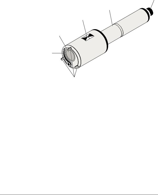
1.2Structure of the IFL 70x IQ sludge level sensor
Structure |
5 |
4
3
2
1
6
Fig. 1-2 Structure of the sludge level sensor (example: IFL 700 IQ)
1 |
Wiper (only IFL 700 IQ) |
|
|
2 |
Ultrasonic transducer |
|
|
3 |
Marking for immersion depth 0.1 m |
|
|
4 |
Shaft |
|
|
5 |
Plug head connector |
|
|
6 |
Leg supports |
|
|
Measuring principle The IFL 70x IQ is based on the ultrasonic measuring principle. Ultrasonic waves transmitted by the ultrasonic transducer are totally or partly reflected by layers at which the density of the measuring medium changes (e.g. sludge blanket, bottom of the basin), and then received again. Based on the reflection intervals, the distance between the levels and the ultrasonic transducer is determined:
1 - 2 |
ba76129e01 |
10/2012 |
IFL 70x IQ |
Overview |
|
|
Ultrasonic transducer
1 
2
Sludge blanket level
 3
3
Bottom
Fig. 1-3 Principle of the ultrasonic measurement
1Transmitted ultrasonic waves
2Echo reflected by the sludge blanket (short reflection interval)
3Echo reflected by the bottom area (long reflection interval)
Wiper (cleaning system) The IFL 700 IQ sensor has a mechanical wiper that effectively cleans gas bubbles and dirt off the ultrasonic transducer. The wiper operates contactless and is maintenance-free and wear-free.
1.3Recommended fields of application
Sludge level control and monitoring in waste water treatment.
Detailed information on the subject of sludge level measurement is given for example in the DWA information sheet no. 256 "Prozessmesstechnik auf Kläranlagen, Teil 8: Messeinrichtungen zur Bestimmung des Schlammspiegels" (Process measuring technique at wastewater treatment plants, part 8: Instrumentation for determination of the sludge level".
ba76129e01 |
10/2012 |
1 - 3 |

Overview |
IFL 70x IQ |
|
|
1 - 4 |
ba76129e01 |
10/2012 |
IFL 70x IQ |
Safety instructions |
|
|
2 Safety instructions
2.1Safety information
2.1.1Safety information in the operating manual
This operating manual provides important information on the safe operation of the product. Read this operating manual thoroughly and make yourself familiar with the product before putting it into operation or working with it. The operating manual must be kept in the vicinity of the meter so you can always find the information you need.
Important safety instructions are highlighted in this operating manual. They are indicated by the warning symbol (triangle) in the left column. The signal word (e.g. "CAUTION") indicates the danger level:
WARNING
indicates a possibly dangerous situation that can lead to serious (irreversible) injury or death if the safety instruction is not followed.
CAUTION
indicates a possibly dangerous situation that can lead to slight (reversible) injury if the safety instruction is not followed.
NOTE
indicates a situation where goods might be damaged if the actions mentioned are not taken.
2.1.2Safety signs on the product
Note all labels, information signs and safety symbols on the product. A warning symbol (triangle) without text refers to safety information in this operating manual.
2.1.3Further documents providing safety information
The following documents provide additional information, which you should observe for your safety when working with the measuring system:
Operating manuals of other components of the IQ SENSOR NET system (power packs, controller, accessories)
Safety datasheets of calibration and maintenance equipment (e.g. cleaning solutions).
ba76129e01 |
10/2012 |
2 - 1 |

Safety instructions |
IFL 70x IQ |
|
|
2.2Safe operation
2.2.1Authorized use
The authorized use of the IFL 70x IQ consists of its use as a sludge level sensor in the IQ SENSOR NET. Only the operation and running of the product according to the instructions and technical specifications given in this operating manual is authorized (see chapter 7 TECHNICAL DATA). Any other use is considered unauthorized.
2.2.2Requirements for safe operation
Note the following points for safe operation:
The product may only be operated according to the authorized use specified above.
The product may only be supplied with power by the energy sources mentioned in this operating manual.
The product may only be operated under the environmental conditions mentioned in this operating manual.
The product may not be opened.
2.2.3Unauthorized use
The product must not be put into operation if:
it is visibly damaged (e.g. after being transported)
it was stored under adverse conditions for a lengthy period of time (storing conditions, see chapter 7 TECHNICAL DATA).
2 - 2 |
ba76129e01 |
10/2012 |
IFL 70x IQ |
Commissioning |
|
|
3 Commissioning
3.1IQ SENSOR NET system requirements
Software statuses of the The operation of the IFL 70x IQ requires the following software vercontroller and terminal sions in the IQ SENSOR NET:
components
|
MIQ/MC2 |
Controller software: |
Version 3.35 or higher |
|
MIQ/TC 2020 XT |
Terminal software: |
Version 3.35 or higher |
3.2Scope of delivery
Sludge level sensor IFL 700 IQ or IFL 701 IQ
Operating manual
3.3Installation
3.3.1General information
NOTE
Sharp objects can damage the ultrasonic transducer. Please be careful, especially when handling sharp tools, when cleaning and during transport.
NOTE (only IFL 700 IQ)
If the sensor is connected to the IQ SENSOR NET, the mechanical wiper may start moving unexpectedly. Make sure that the swivel range of the wiper is always free. Only put the sensor down on its leg supports on a flat surface with the ultrasonic transducer pointing downward.
ba76129e01 |
10/2012 |
3 - 1 |

Commissioning |
IFL 70x IQ |
|
|
3.3.2General installation conditions
Minimum distance |
= 0.2 m + 0.05 * (water depth - immersion depth in m) |
|
from basin wall |
||
|
||
|
|
|
Immersion depth |
Wall |
|
(= 0.1 m) |
|
|
Immersion depth |
|
|
Dead zone |
|
|
(= 0.4 m) |
|
|
Vertical |
|
|
installation |
|
|
Depth of the |
|
|
sludge level |
obstacles |
Water |
|
|
|
and |
|
depth |
Measurement cone approx. 7° |
|
|
(half-value angle) |
|
|
freeoffixtures |
|
|
Sludge level |
|
|
Height of the |
|
|
sludge level |
|
Bottom of the basin
Fig. 3-1 Ideal installation environment
3 - 2 |
ba76129e01 |
10/2012 |

IFL 70x IQ |
Commissioning |
|
|
Sensor installation The following conditions should always be met:
Vertical
Sufficient distance from the basin wall (minimum distance, see formula in Fig. 3-1).
If the distance to the wall of the basin is small, the wall should be rather smooth.
Immersion depth (0.05 m ... 3 m)
Minimum distance between the sensor bottom and sludge blanket = 0.4 m ("dead zone").
Ideally, at the installation location the ultrasonic cone is free of barriers that move the sensor from its position or cross the measuring cone and thus cause interfering echoes.
Additional measures are required in order to minimize negative impacts (see section 3.3.5).
3.3.3Influence of permanently installed fixtures
Permanently installed fixtures in the vicinity of the measuring cone reflect the ultrasonic waves transmitted and thus cause interfering echoes.
If there are permanently installed fixtures in the expectation range of the sludge blanket level, it is not possible to clearly assign an echo to a sludge level. In this case, a different installation location must be selected (e.g. with a greater distance from the wall). Alternatively, the evaluation range can be adjusted.
3.3.4Influence of gas bubbles and suspended particles
Gas bubbles and suspended particles reduce the propagation of ultrasonic waves. A high concentration of gas bubbles and suspended particles can in extreme cases lower the range of the sensor.
If there are range problems, the sensor must be immersed deeper (note the dead zone and maximum depth of immersion).
With the IFL 700 IQ sensor, the mechanical wiper removes gas bubbles and dirt from the surface of the ultrasonic transducer.
ba76129e01 |
10/2012 |
3 - 3 |

Commissioning |
IFL 70x IQ |
|
|
Connection cable
Are the plug connections dry?
Connecting the sensor to the sensor connection cable
3.3.5Short-term interferences due to obstacles
Certain events may for a short period of time affect or interrupt the measurement. In waste water treatment plants, these events are normally:
Moving scrapers that displace an installed sensor from its measuring position or cross its measuring cone.
Fixtures permanently installed in the basin such as pipes or scrapers that are touched by the measuring cone of a sensor on a scraper bridge when rotating.
Interferences due to obstacles can be suppressed with the aid of certain settings (see setting table, section 3.5).
The default settings may have to be adjusted as necessary.
A tilting armature is available for installation in basins with a chain scraper or linear scraper for scum removal. Thus the sensor is temporarily pulled out of the basin by the moving scraper.
3.3.6Connecting the sensor
A sensor connection cable of the SACIQ or SACIQ SW type is required to connect the sensor. The cable is available in different lengths. Compared to the SACIQ standard model, the SACIQ SW sensor connection cable is optimized concerning its resistance to corrosion. Information on this and other IQ SENSOR NET accessories is given in the YSI catalog and on the Internet.
How to connect the SACIQ (SW) sensor connection cable to the terminal strip of an MIQ module is described in chapter 3 INSTALLATION of the IQ SENSOR NET system operating manual.
Before connecting the sensor and sensor connection cable, please make sure the plug connections are dry. If moisture gets into the plug connections, first dry the plug connections (dab them dry or blow them dry using compressed air).
Do not suspend the sensor on the sensor connection cable. Use a sensor holder or an armature. Information on this and other IQ SENSOR NET accessories is given in the YSI catalog and on the Internet.
1Take the protective caps off the plug connections of the sensor and the SACIQ (SW) sensor connection cable and keep them safe.
3 - 4 |
ba76129e01 |
10/2012 |
Loading...