


USER MANUAL
ITEM# 626973-01REF
REVISION F
ProDIGITAL User Manual
PROFESSIONAL SERIES DIGITAL HANDHELD METERS

The information contained in this manual is subject to change without notice.
Effort has been made to make the information in this manual complete, accurate, and current.
The manufacturer shall not be held responsible for errors or omissions in this manual.
Consult YSI.com for the most up-to-date version of this manual.
Thank you for purchasing a YSI Professional Series Digital handheld meter. This manual covers setup, operation, and functionality of the ProDIGITAL handhelds which include the ProDSS and ProSolo.
ProDIGITAL Handheld features include:
•Digital smart probes that are automatically recognized by the instrument when connected
•Waterproof (IP-67) case
•Long-life rechargeable lithium-ion battery pack
•Color display and backlit keypad
•User-selectable cable options
•USB connectivity
•Global Positioning System (GPS) (optional on ProDSS)
•Depth sensor (optional on 4-port cable)
•Large memory with extensive site list capabilities
•Rugged enclosure with rubber over-molded case and miltary-spec (MS) connectors
•KorDSS data management software included with each instrument (Please see Installation Instructions)
Safety Information
Please read this entire manual before unpacking, setting up or operating this equipment. Pay attention to all precautionary statements. Failure to do so could result in serious injury to the operator or damage to the equipment. Do not use or install this equipment in any manner other than that specified in this manual.
The manufacturer is not responsible for any damages due to misapplication or misuse of this product including, without limitation, direct, incidental and consequential damages, and disclaims such damages to the full extent permitted under applicable law. The user is solely responsible to identify critical application risks and install appropriate mechanisms to protect processes during a possible equipment malfunction.
Precautionary Symbols
NOTE: Information that requires special emphasis
NOTICE: Indicates a situation which, if not avoided, may cause damage to the instrument
 CAUTION: Indicates a potentially hazardous situation that may result in minor or moderate injury
WARNING: Indicates a potentially or imminently hazardous situation which, if not avoided, could result in death or serious injury
Product Components
Carefully unpack the instrument and accessories and inspect for damage. If any parts or materials are damaged, contact YSI Customer Service at 800-897-4151 (+1 937 767-7241) or the authorized YSI distributor from whom the instrument was purchased.

TABLE OF CONTENTS
1. Introduction |
4. Maintenance and Storage |
||
1.1 |
Battery Use and Battery Life |
4.1 |
ProDIGITAL Handheld |
1.2 |
Charging the Battery Pack |
4.2 |
4-Port Bulkhead |
1.3 |
Battery Replacement |
4.3 |
Sensor Guard |
1.4 |
Connect the Handheld to the Cable Assembly |
4.4 |
Depth Sensor |
1.5 |
Sensor Installation/Removal |
4.5 |
Temperature Sensor |
|
|
4.6 |
Conductivity Sensor |
2. Operation |
4.7 |
Optical Dissolved Oxygen Sensor |
|
2.1 |
Keypad and Navigation |
4.8 |
Turbidity & Total Algae Sensors |
2.2 |
Startup |
4.9 |
pH/ORP Sensor |
2.3 |
Navigation |
4.10 |
ISE Sensor |
2.4 |
Main Display Description |
4.11 |
ProDSS Sensor Module Replacement |
2.5System Menu
2.6 |
Sensor Menu |
5. KorDSS Software |
|
2.7 |
Calibration Menu |
5.1 |
Introduction |
2.8 |
Files Menu |
5.2 |
Installing the Driver and Software |
2.9Taking Measurements
|
6. Accessories |
3. Calibration |
6.1 Ordering |
3.1Calibration Setup
3.2 |
Depth |
7. Safety and Support |
|
3.3 |
Conductivity |
7.1 |
Rechargeable Lithium-Ion Battery Pack |
3.4 |
Barometer |
7.2 |
Service Information |
3.5 |
Dissolved Oxygen |
7.3 |
Technical Support |
3.6 |
Turbidity |
7.4 |
Declarations of Conformity |
3.7 |
Total Algae |
7.5 |
Warranty |
3.8pH/ORP
3.9 ISEs |
8. Appendices |
|||
|
|
|
8.1 |
Appendix A - DO% Calibration Values |
|
|
|
8.2 |
Appendix B - Oxygen Solubility Table |
|
|
|
||
|
|
|
|
|
THIS IS AN
INTERACTIVE DOCUMENT
When viewing this document as an AdobeTM PDF, hovering your cursor over certain phrases will bring up the finger-point icon. Clicking elements of the Table of Contents, website URLs, or references to certain sections will take you automatically to those locations.
3
1. Introduction
1.1Battery Use and Battery Life
ProSeries Digital handhelds use a rechargeable lithium-ion (Li-Ion) battery pack as a power source. The battery comes pre-installed in the handheld and ships at less than 50% full capacity. Battery life depends on use, enabled parameters, LCD brightness, and GPS use.
A new battery, that has been fully charged, is expected to last for the following durations at 25°C, with Sampling set to Auto, Backlight set to Auto, and GPS enabled:
•ProDIGITAL handheld only - 48 hours
•ProDSS with fully loaded 4-port cable assembly and 25% LCD brightness - 20 hours
To increase battery life, enable manual sampling mode (Sampling). Manual sampling mode powers the sensor(s) on to take a measurement and then powers down to conserve battery life.
As with all lithium-ion batteires, battery life will decline over time and use. This decay should be expected. For the longterm health of the battery, a larger discharge is better than a small dishcarge between recharges.
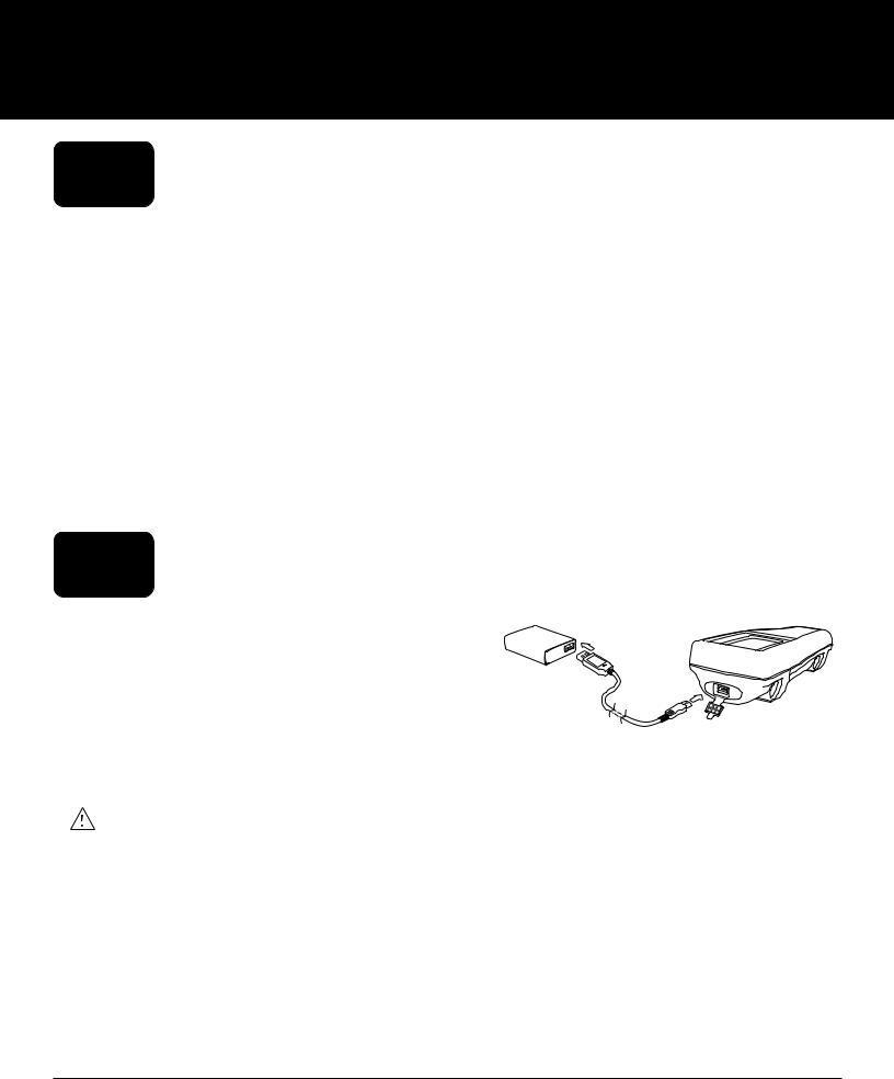
1.2Charging the Battery Pack
A USB cable is included with the handheld to charge the instrument battery pack and connect the instrument to a PC. The battery pack can be charged from the AC power adapter, directly from a computer USB connection or from an external, portable USB battery pack (sold separately, see Accessories).
Plug the USB connector into the AC power adapter, computer USB connector or external USB battery pack, then plug the micro USB connector into the handheld (Figure 1).
Figure 1 Connecting the handheld to AC power supply
WARNING: Charge the battery pack in an open area away from flammable materials, liquids, and surfaces. Do not charge or handle a battery pack that is hot to the touch. Failure to follow the safety warnings and precautions can result in personal injury and/or instrument damage not covered under warranty. Read Rechargeable Lithium-Ion battery pack safety warnings and precautions.
For the handheld to recognize that it is using AC power, you must start charging the handheld while it is turned on. After the instrument recognizes it is being charged, it can be turned off to finish charging.
AC Charging |
DC Charging |
|
|
9 hr |
14 hr |
|
|
4 |
Introduction |

1.3Battery Replacement
1.Remove the battery pack cover by unscrewing (counter-clockwise) the four screws with a flat or Phillips head screwdriver (Figure 2). The retaining screws are captured into the battery pack cover and are not removable.
2.If replacing an existing battery pack, remove the Li-Ion battery pack and rubber battery pack cradle. With two fingers, grasp the battery pack connector and pull the connector straight up to disconnect and remove. Properly dispose of the old battery pack (See Battery Disposal).
3.Inspect the replacement battery pack and battery pack cradle for damage. Contact YSI technical support if there is any damage.
4.Correctly align and seat the battery pack cradle and battery pack into the instrument.
5.Align the battery pack connector wire terminals with the three instrument pins, then connect the battery pack to the instrument. Make sure that the three wire terminal connectors and three instrument pins are correctly aligned before connecting the battery pack connector. Incorrect installation can damage the battery pack connectors or instrument pins.
6.Install the battery pack cover, then hand tighten the cover screws with a screwdriver. DO NOT use any power tools. Make sure that the cover sealing surface is correctly aligned and free of any contamination or damage.
NOTICE: The battery cover does NOT need to make a compressed seal. Overtightening the cover screws can damage the battery cover and the handheld.
1 |
|
2 |
3 |
|
4
5
|
1 |
Battery pack cover |
|
|
|
|
2 |
Battery pack |
|
|
|
|
3 |
Battery pack connector* |
6 |
|
|
4 |
Instrument pin connectors |
|
|
|
|
|
5 |
Battery pack cradle |
|
|
|
|
6 |
Battery pack cradle installed |
|
|
|
*Color shown for reference
Figure 2 Battery replacement
Introduction |
5 |
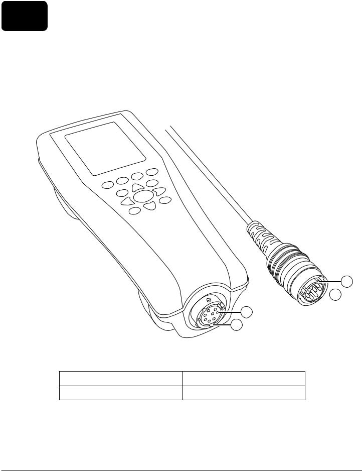
1.4Connect the Handheld to the Cable Assembly
The cable connectors are keyed for positive mating and to prevent connector damage (Figure 3). The handheld retains its IP-67 waterproof rating when the cable is disconnected. However, the connectors are not wet-mateable and should be clean and dry before connecting.
Align the keys on the cable connector with the slots on the handheld connector. Push together firmly, then twist the outer ring clockwise until it locks into place.
3
 4
4
|
|
|
1 |
|
|
|
2 |
|
Figure 3 Keyed connectors |
||
1 |
Handheld female connector |
3 |
Keyed area of connector |
2 |
Slotted area of connector |
4 |
Cable male connector |
6 |
Introduction |
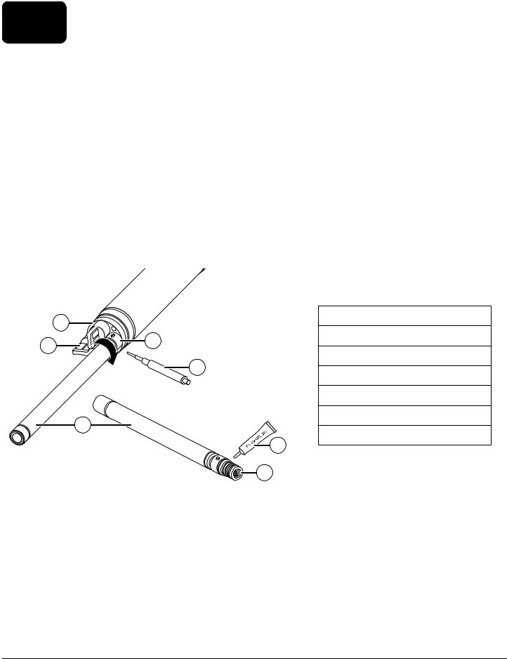
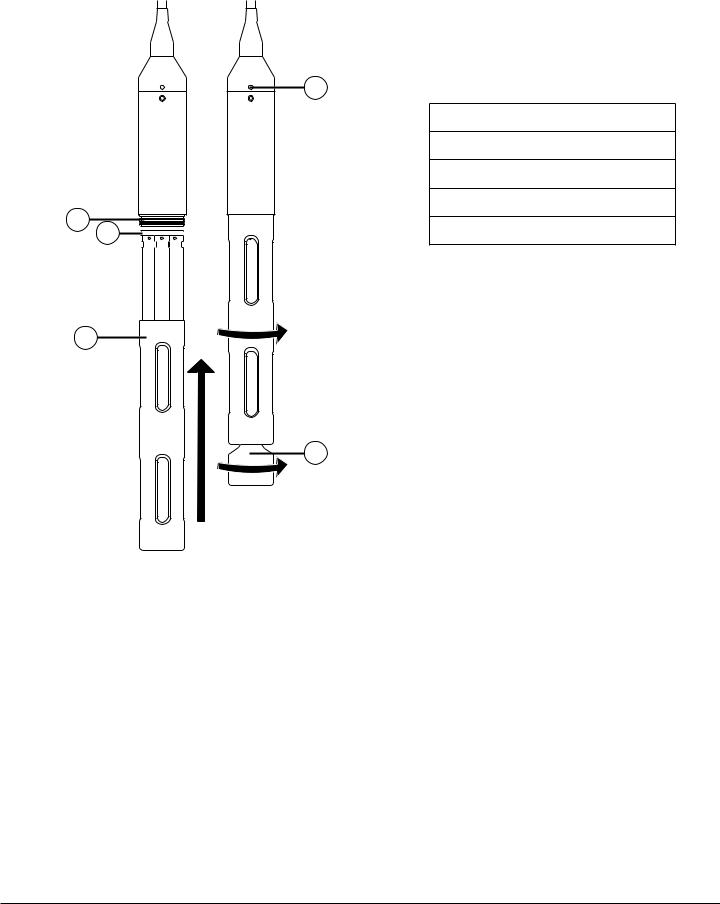
1.5Sensor Installation/Removal
Probe assemblies like the ODO/CT, ODO/T, and ProOBOD feature integral sensors. These sensors cannot be removed from the cable. Therefore, this section pertains only to the ProDSS 4-port cable.
ProDSS 4-port Cable
ProDSS 4-port cables feature user-replaceable sensors. The ports on the bulkhead are universal, meaning that you can install any sensor into any port. A conductivity/temperature sensor must be installed for accurate measurement of all parameters except turbidity and TSS.
Bulkhead ports are numbered (Figure 4), so if multiple sensors of the same type are installed, the port number will be added to the Run screen display to clarify the measurement value of each sensor.
NOTICE: The bulkhead ports and sensor connectors are not wet-mateable. Make sure that the sensor connectors and bulkhead ports are clean and dry before sensor installation.
|
3 |
|
|
1 |
Sensor |
|
|
|
|
|
|
2 |
|
4 |
|
2 |
Port plug |
|
|
|
|
||
|
|
|
3 |
Bulkhead |
|
|
|
|
|
||
|
|
|
5 |
4 |
Sensor retaining nut |
|
|
|
|
||
|
|
|
|
5 |
Sensor installation/removal tool |
|
|
1 |
|
6 |
O-ring lubricant |
|
|
|
7 |
Sensor port |
|
|
|
|
|
||
|
|
|
|
6 |
|
7
Figure 4 Sensor installation
Sensor Installation
1.Remove the port cover shipped with the 4-port cable. This cover can be kept to protect the bulkhead ports from contamination during long-term storage.
2.Inspect each bulkhead port for contamination. If the port is dirty or wet, clean it with compressed air.
3.Apply a thin coat of o-ring lubricant to the sensor o-rings. Wipe off excess o-ring grease with a lint-free cloth.
4.Carefully align the sensor and bulkhead connectors by inserting the sensor into the port then gently rotating the sensor until the connectors align. Once aligned, push the sensor toward the bulkhead until the sensor seats in the port.
Introduction |
7 |
5.Carefully finger-tighten the retaining nut clockwise. If any resistance is felt, loosen the retaining nut completely to prevent cross-threading.
6.Use the sensor installation/removal tool to tighten the retaining nut clockwise until snug, about a ¼ to ½ additional turn of the retaining nut. Be careful not to over-tighten the retaining nut.
NOTICE: Incorrect installation or over-tightening can cause damage to the sensor or bulkhead that is not covered by the warranty.
Sensor Removal
To remove a sensor, insert the sensor installation/removal tool into the retaining nut, then rotate the retaining nut counterclockwise to loosen. After the retaining nut has been completely unscrewed from the bulkhead, pull the sensor straight out of the port and place it on a clean surface. Install a port plug if not reinstalling a sensor in the exposed port. Exposure to water can cause damage or corrosion to the bulkhead connectors not covered by the warranty.
Figure 5 Sensor port plugs and port numbering (4-port cables)
Port plugs
Port plugs and a tube of o-ring lubricant are included in the maintenance kit that ships with all 4-port cables.
Installation
1.Apply a thin coat of o-ring lubricant to the o-rings on the plug port.
2.Remove any excess lubricant from the o-rings and port plug with a lint-free cloth.
3.Insert the port plug into the empty port and press until firmly seated.
4.Finger-tighten the port plug clockwise to install. If necessary, use the sensor installation tool to make sure that the plug is fully seated into the port. The o-rings will not be visible if a port plug is correctly installed. Do not over-tighten the port plug.
NOTICE: Do not submerge the bulkhead without a sensor or port plug installed in all ports.
Sensor Guard and Weight Installation
1.Carefully slide the sensor guard over the bulkhead and attached sensors/port plugs. Push the sensor guard toward the bulkhead until the sensor guard threads align with the bulkhead threads.
2.Carefully hand-tighten the sensor guard clockwise. If any resistance is felt, loosen the sensor guard completely to prevent cross-threading. Incorrect installation may cause damage to the sensor guard or bulkhead that is not covered by the warranty.
8 |
Introduction |
Sensor Guard and Weight Installation (continued)
1
2
3 |
4
5
1 Depth sensor (if equipped)
2 Bulkhead threads
3 Bulkhead
4 Sensor guard
5 Weight
Figure 6 Sensor guard and weight installation on a 4-port cable assembly
Sensor Guard Weights
To help stabilize the sensors when profiling at deeper depths, a 1 lb. sensor guard weight is supplied with 4-port assemblies 10 meters and longer. To attach the weight, carefully hand-tighten it clockwise on to the bottom of the sensor guard (Figure 6). If any resistance is felt, loosen the sensor guard weight completely to prevent cross-threading.
The bottom of the weight is threaded so that additional weights can be added if needed. YSI recommends installing no more than 5 lbs of weight on ProDIGITAL cables. See Accessories.
NOTE: Do not have any weights installed on the sensor guard when calibrating using the calibration cup.
Introduction |
9 |
2. Operation
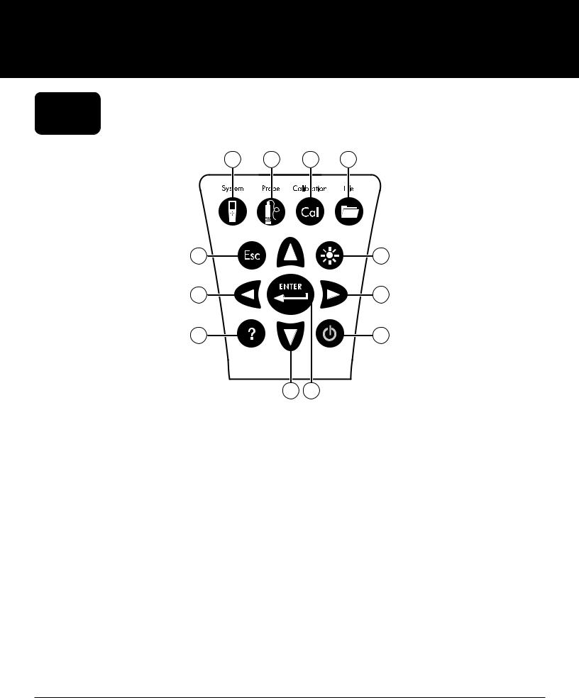
2.1Keypad and Navigation
1 |
2 |
3 |
4 |
5 |
6 |
7 |
8 |
9 |
10 |
|
11 |
12 |
||
|
Figure 7 Keypad description |
|||
|
|
|
|
|
1 |
System: Opens the system menu. Use to adjust |
7 |
|
Left arrow key: Navigate left in an alpha/numeric |
|
system settings. |
|
|
entry screen. Push to return to previous menu in all |
|
|
|
|
screens except alpha/numeric entry. On the Run |
|
|
|
|
screen, push to show graphical representations of the |
|
|
|
|
displayed measurements. |
|
|
|
|
|
2 |
Probe: Opens the sensor menu. Use to setup sensors, |
8 |
|
Right arrow key: Navigate right in an alpha/ |
|
change the units shown, select the sensor averaging |
|
|
numeric entry screen. On the Run screen, push to |
|
mode, and turn on/off Auto Stable and GPS. |
|
|
show graphical representations of the displayed |
|
|
|
|
measurements. In the View Data screen, push to view |
|
|
|
|
additional parameters in the data set. |
|
|
|
|
|
3 |
Calibrate: Opens the calibration menu. Use to |
9 |
|
Help: Shows context sensitive help. |
|
calibrate sensors or restore default calibration. |
|
|
|
4 |
File: Opens the file menu. Use to view logged data |
10 |
ON/OFF: Turn on or turn off the instrument. |
|
|
and calibration files, backup data to a USB stick, and |
|
|
|
|
delete data. |
|
|
|
5 |
Exit/Escape key: Exits to the Run screen. When in an |
11 |
Up/Down arrow keys: Scroll through menus or enter |
|
|
alpha/numeric entry screen, returns to previous menu. |
|
|
numbers and letters. |
|
|
|
|
|
6 |
Backlight: Turns the keypad backlight on or off for use |
12 |
Enter key: Push to confirm selections. On the Run |
|
|
in low light conditions. |
|
|
screen, push to log a single data point or start |
|
|
|
|
continuous data logging. |
|
|
|
|
|
10 |
Operation |
2.2Startup
Push the On/Off (  ) key to turn on the handheld. If the handheld does not turn on, make sure that the battery is charged. Push and hold the
  key for 1.5 seconds to turn the handheld off.
2.3Navigation
The handheld contains menus to change user-defined options, functions, and parameters. Use the arrow keys
( and
and  ) to highlight different options within menus and sub-menus, then push the Enter ( ENTER ) key to select the option. Push the left arrow (
 ) key to return to the previous menu.
Push the Exit/Escape ( Esc ) key to return to the Run screen. To enable or disable an option, highlight the option, then push the ENTER key. Enabled functions appear as a circle with a dot (  ) or a box with a check mark (
  ). Disabled
functions appear as a circle only ( ) or an empty box ( |
). |
Alpha/Numeric Entry
When required, an alpha/numeric entry screen will be shown. Use the arrow keys to highlight a specific character and
push the ENTER key to select it for entry. When finished entering information, highlight ENTER, then push the ENTER key to save the entry (Figure 8).
NOTE: When in an alpha/numeric screen, the key is for alpha/numeric navigation only. Push the Esc key to cancel and return to the previous menu.
1 |
1 |
|
|
|
1 |
User entry field |
|||
|
|
|||
|
|
|
|
|
|
2 |
2 |
Delete entire entry |
|
|
|
3 |
Backspace |
|
|
3 |
|
|
|
|
4 |
Enter (highlighted selection) |
||
|
|
|||
|
|
|
|
|
|
|
5 |
Upper/lowercase |
|
|
|
|
|
2
4 |
4 |
5 3
Figure 8 Alpha/numeric and numeric entry screens
Operation |
11 |
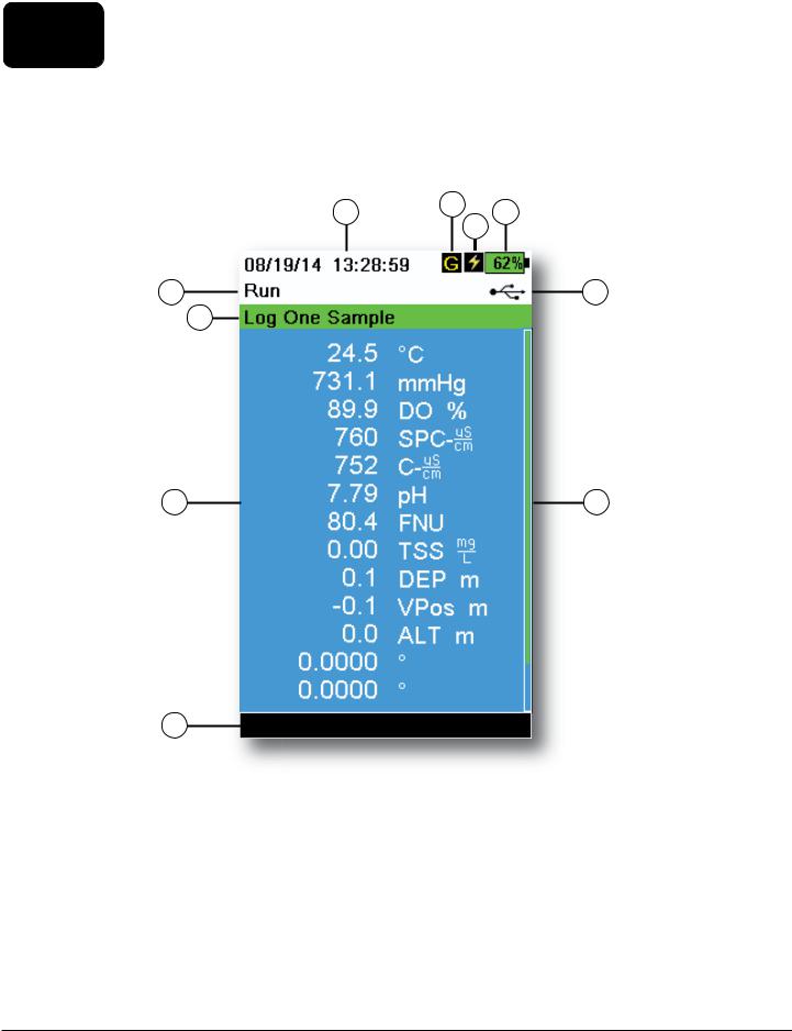
2.4Main Display Description
The main display (Run screen) shows the current measurements and units as defined in the Sensor Display menu. If more measurements are selected than can be displayed on the Run screen, a scroll bar will be shown. Use the  and
and  arrow keys to view the additional measurements (Figure 9).
The message area shows status messages, error messages, and information about selected functions.
1 |
2 |
4 |
|
||
|
|
3 |
5 |
|
6 |
7 |
|
|
8 |
9 |
10
Figure 9 Main display example
1 |
Date/Time |
6 |
USB/PC connection indicator |
|
|
|
|
2 |
GPS signal indicator |
7 |
Log or sampling (update measurements) prompt on |
|
|
|
Run screen (single or continuous) |
3 |
Battery charging indicator |
8 |
Displayed measurements |
|
|
|
|
4 |
Battery charge % |
9 |
Scroll bar |
|
|
|
|
5 |
Current screen/menu |
10 |
Message area |
|
|
|
|
12 |
Operation |
2.5System Menu
Push the System (  ) key to view and adjust instrument settings. Highlight a sub-menu then push the ENTER key to view the sub-menu options (Figure 10).
Pre-defined or user-selected options are noted within brackets ( [ ] ).
|
|
|
|
|
|
|
1 |
Set the Date and Time |
|
|
|
|
|
|
|
|
|
1 |
|
|
|
|
|
|
2 |
Change the user-defined Calibration Options |
|
|
|
|
|
|
|
|
|
2 |
|
|
|
|
|
3 |
Change the instrument Language settings |
|
|
|
|
|
|
||||
3 |
|
|
||||||
|
|
|
|
|||||
4 |
|
|
|
|
|
4 |
Change the Radix Point |
|
|
|
|
|
|
||||
5 |
|
|
|
|
|
|
||
|
|
|
|
|
|
|
|
|
|
|
|
|
|
|
|
|
|
6 |
|
|
|
|
|
5 |
Change the Logging options |
|
|
|
7 |
|
|
||||
|
|
|
|
|
|
|
|
|
8 |
|
|
|
|
6 |
Change the Sampling options |
||
|
|
|
|
|
||||
|
|
|
|
|
||||
9 |
|
|
|
|
|
|
|
|
|
|
|
|
|
|
7 |
Set the handheld Auto-Shutoff time |
|
10 |
|
|
|
|
||||
|
|
|
|
|
|
|||
11 |
|
|
8 |
Set the Backlight mode |
||||
12 |
|
|
|
|
||||
|
|
|
|
|
|
|||
|
|
|
|
|
|
|||
13 |
|
|
|
|
|
|
9 |
View the Software Version |
|
|
|
|
|
|
|||
|
|
|
|
|
|
|
|
|
|
|
|
|
|
|
|
10 View the handheld Serial Number |
|
|
|
|
|
|
|
|
|
|
|
|
|
|
|
|
|
11 View and adjust the Unit ID |
|
|
|
|
|
|
|
|
|
|
|
|
|
|
|
|
|
12 View the Sensor specific information |
|
|
|
|
|
|
|
|
|
|
|
|
Figure 10 |
System menu |
13 Adjust the display Brightness |
||||
|
|
|
|
|||||
Date/Time
|
|
|
|
→ Date/Time |
|
|
|
|
|
|
|
For accurate logging and calibration data, correctly set the date and time |
||
|
|
options (Figure 11). Select any of the following options to set the Date/ |
||
|
|
Time. |
||
|
|
Date/Time options: |
||
Figure 11 |
Date/Time |
|
|
• Set YY/MM/DD, MM/DD/YY, DD/MM/YY or YY/DD/MM date format |
|
|
• Set the correct date |
||
|
|
|
|
|
|
|
|
|
• Select 12 or 24 hour time format |
|
|
|
|
• Set the correct time |
Operation |
13 |
Calibration Record
Detailed sensor calibration information is stored for later review. The instrument’s internal memory can save up to 400 individual calibration records. After 400 records, the instrument will overwrite previously stored calibration records, starting with the oldest. To prevent the permanent loss of calibration records, periodically download the calibration files to a computer using the KorDSS software.
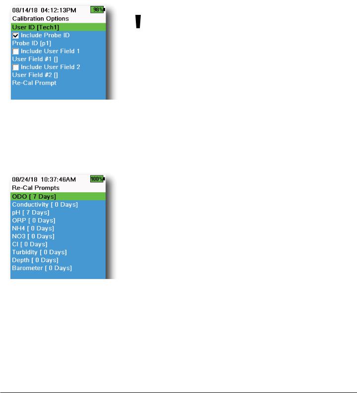
Calibration Options
|
|
|
→ Calibration Record → Options |
|
|
|
|
|
User ID, Probe ID, or User Field #1 or 2 can be user-defined for positive |
||
|
calibration file identification of: |
||
|
|
|
• The person calibrating the instrument |
|
|
|
• The sensor/cable serial number used during calibration (or other, |
|
|
|
user-defined Probe ID) |
|
|
|
• Other user-specific identification (User Field #1 and #2) (Figure 12) |
Figure 12 Calibration Options |
|
|
NOTE: User Field can be used to describe the condition of the |
|
|
|
|
|
|
|
probe. For example, new sensor or new ODO cap. |
Re-Cal Prompts
 → Calibration Record → Options → Re-Cal Prompts
Re-Cal Prompts provide a reminder to recalibrate a probe in the user-defined number of days (Figure 13). Select the desired sensor Re-Cal prompt, then enter the desired number of days before the Re-Cal prompt occurs. This reminder will be provided when the instrument is powered on and will reoccur every day until the sensor is re-calibrated.
Set the sensor value to zero (0) days (default) to turn off Re-Cal prompts.
Figure 13 Re-Cal Prompts
14 |
Operation |
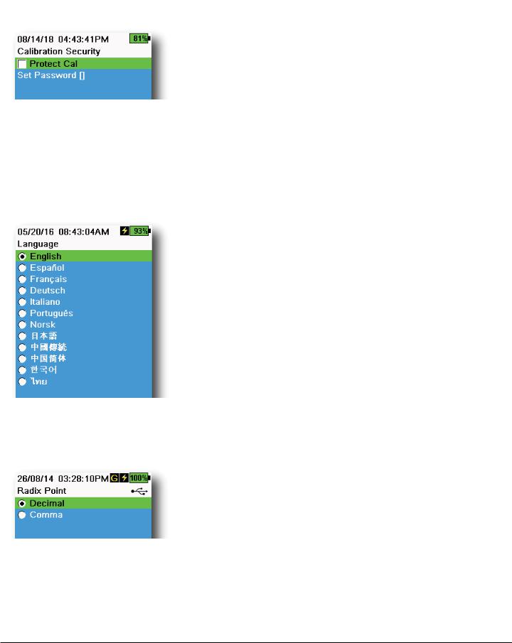
Figure 14 Calibration Security
Figure 15 Language
Figure 16 Radix Point
Calibration Security
 → Calibration Record → Security
The Calibration menu can be password protected to prevent accidental or unauthorized sensor calibration (Figure 14).
1.From the Calibration Record menu, select Security, then enter the default password “ysi123”.
2.Select Set Password [ ] and change the default password.
3.Select the Protect Cal check box to password protect the Calibration menu.
NOTE: Write down and keep the password in a safe place. Contact YSI Technical Support if you lose the password (Technical support).
Language
 → Language
The instrument is shipped with English enabled. If a different language is desired and selected, the handheld will take approximately 10 to 20 seconds to enable the new language (during the first installation only).
Optional languages: |
|
• Spanish |
• Japanese |
• French |
• Simplified Chinese |
• German |
• Traditional Chinese |
• Italian |
• Korean |
• Portuguese |
• Thai |
• Norwegian |
|
Radix Point
 → Radix Point
The radix point can be changed to display a comma or a decimal in numeric displays (e.g. 1.00 becomes 1,00 when Comma is selected) (Figure 16).
Operation |
15 |
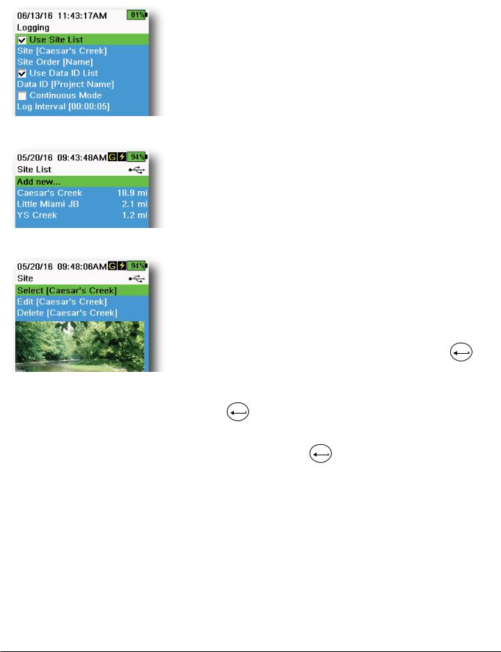
Figure 17 Logging
Figure 18 Site List
Figure 19 Site
Logging
 → Logging
The handheld can add a user-defined Site and/or Data ID to a data record if these functions are enabled under the Logging menu. A check mark in the box next to these features indicates they are enabled (Figure 17).
After selecting Site [ ] or Data ID [ ], the Site List or Data ID List will be
shown (Figure 18). New entries can be created by choosing Add new...
If the handheld has a GPS signal, the current GPS coordinates will be auto-populated when creating a new site. If the handheld does not have a built-in GPS, the coordinates and altitude can be entered manually.
Sites can be listed in order of Name (i.e. alphanumeric order) or Distance from the current position (Figure 18).
Choose an entry from the Site List or Data ID List to Select, Edit, or Delete (Figure 19). When selected, data recorded will be tagged with the specific site and/or data ID.
NOTE: The Manage Sites menu in KorDSS Software can be used to send a picture of the Site to the instrument.
Continuous Mode (Interval logging): Select the Continuous Mode check box and enter the user-defined Log Interval (in hours:minutes:seconds) to log samples continuously at the specified time interval. The Run screen
will display Start Logging... when in Continuous Mode. Press ENTER to begin logging.
One sample logging: Clear the Continuous Mode check box. The Run screen will display Log One Sample. A sample will be logged each
time the ENTER key is pushed when in the Run screen.
NOTE: An option to change Site and/or Data ID (if enabled) appears once ENTER is pressed to begin logging.
16 |
Operation |
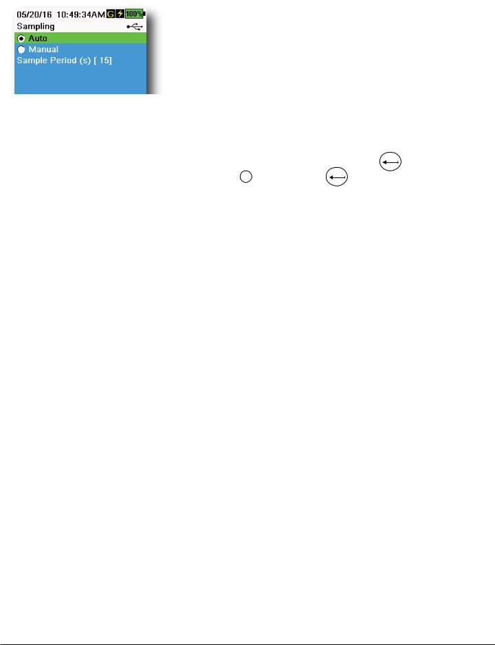
Sampling
 → Sampling
Auto sampling mode continuously updates measurements on the display (Figure 20).
When in Manual mode, the instrument will take measurements for the du- Figure 20 Sampling ration of the user-defined Sample Period (in seconds) then “lock” or hold the readings on the display. The default sample period is 50 seconds, and
can be adjusted from 15 to 60 seconds. Manual mode helps conserve battery power.
Once the measurements are locked, push the ENTER key to log the held data, or the Esc key and then the ENTER key to take a new measurement.
NOTE: When both Continuous Logging Mode and Manual Sampling mode are enabled, the handheld will power the sensors on and take measurements for 15 seconds before logging a data set.
Auto-Shutoff
 → Auto-Shutoff
To conserve battery power, auto-shutoff powers off the instrument after a user-defined time period (in minutes). The auto-shutoff time can be adjusted from 1 to 255 minutes. Set to 0 (zero) to disable Auto-Shutoff.
Backlight
 → Backlight
In Automatic mode, the instrument display will dim 60 seconds after the last key was pushed. Once any key is pushed, the instrument display will return to the user-defined brightness setting and the keypad backlight will turn on. The screen will dim and the keypad backlight will turn off after another 60 seconds of inactivity.
In manual mode, the instrument display remains at the user-defined brightness and the keypad backlight is turned on and off by the Backlight key. Setting the backlight to manual mode is recommended for bright conditions.
Operation |
17 |
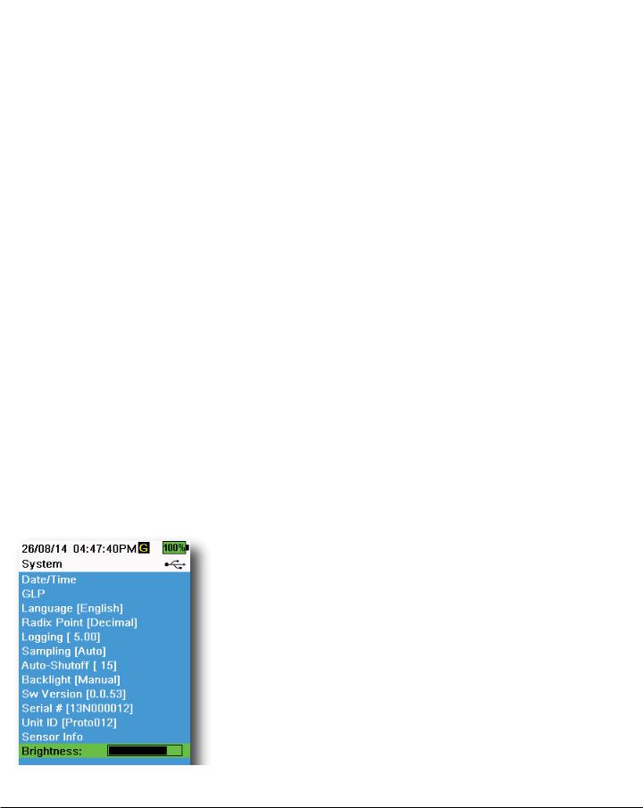
Software (Sw) Version
 → Sw Version
Sw Version shows the instrument’s software version number. The latest instrument software and update instructions are available at YSI.com. Instrument software can be updated through the KorDSS Software under the Instrument and Sensors tab.
Serial #
 → Serial #
Serial # shows the serial number of the handheld instrument. Note the serial number when contacting YSI support.
Unit ID
 → Unit ID
Users can set a custom Unit ID. The Unit ID identifies the instrument in
KorDSS Software.
Sensor Info
 → Sensor Info
Sensor info shows measurement data, and hardware/software information for each component of the system: instrument, sensor, and bulkhead. Use the  and
and  arrow keys to scroll through the components.
Brightness
 → Brightness
The screen brightness can be adjusted to accommodate lighting conditions and to conserve battery power (Figure 21). Use the  and
and  arrow keys to adjust the screen brightness.
Figure 21 Display Brightness
18 |
Operation |
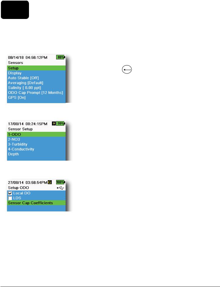
2.6Sensor Menu
Use the Probe ( ) key to access the Sensor menu and change sensor settings (if applicable), enable the measurement units displayed on the Run screen, set Auto Stable parameters, change the sensor averaging mode, and if equipped, turn on/off GPS.
Figure 22 Probe (Sensor) menu
Figure 23 Sensor Setup
Figure 24 Setup ODO
Push the  key to access the sensor menu (Figure 22). Highlight a submenu then push the ENTER key to view sub-menu options.
Pre-defined or user-selected sensor settings are noted within brackets ([]).
Sensor Setup
 → Setup
The Sensor Setup menu will show all sensors connected to the instrument (Figure 23). If a sensor is connected but is not listed on the Sensor Setup menu (<None> displayed), check the sensor and cable connections.
Setup ODO
 → Setup → ODO
Local DO: Enable or disable localized DO% measurements. When enabled, the calibration value is set to 100% regardless of altitude or barometric pressure. When enabled, an L will be shown next to DO% on the run screen. DO mg/L measurements are unaffected when Local DO is enabled (Figure 24).
LDS: Last Digit Supression (LDS) rounds the DO value to the nearest tenth, e.g. 8.27 mg/L becomes 8.3 mg/L.
Sensor Cap Coefficients: The sensor cap coefficients must be updated after sensor cap replacement. Update the sensor cap coefficients using the coefficient sheet provided with the new sensor cap. Once updated, the coefficients are saved to the ODO sensor and do not need to be re-entered.
NOTE: The coefficients stay with the sensor even when used with different handheld meters.
Operation |
19 |
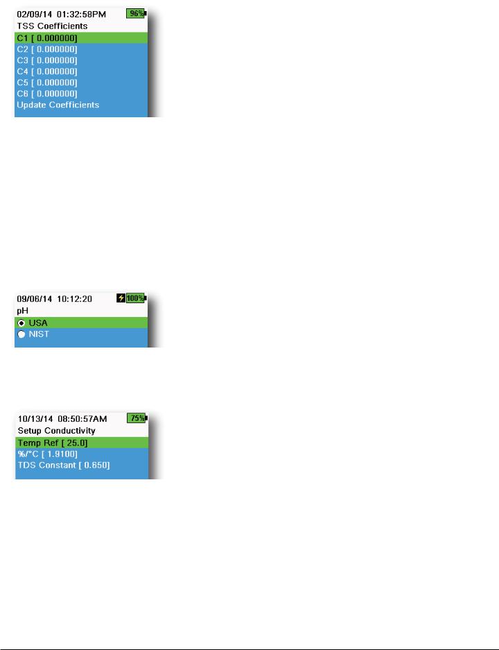
Figure 25 TSS coefficients
Figure 26 Setup pH
Figure 27 Setup Conductivity
Setup Turbidity
 → Setup → Turbidity
TSS Coefficients: Total Suspended Solids (TSS) can be measured if correlation coefficients are calculated in KorDSS.
To obtain these coefficients, collect turbidity data at the sampling site with corresponding grab samples. Analyze the samples in a lab to determine a true TSS measurement (mg/L). At least 2 and up to 6 value pairs of turbidity and TSS measurements can be used.
Correlation data must be collected for each unique sampling site, as this correlation is site-specific.
In KorDSS Software, enter the field-obtained turbidity measurements and the corresponding lab-obtained TSS measurements in the Instrument and Sensors menu. Coefficients can then calculated with KorDSS and sent to the sensor.
NOTE: Although correlation coefficients can be entered directly into the handheld (Figure 25), only KorDSS Software can calculate the coefficients.
Setup pH
 → Setup → pH
Select USA auto-buffer recognition (4.00, 7.00, and 10.00) or NIST autobuffer recognition (4.01, 6.86, and 9.18) (Figure 26). Calibration values are automatically compensated for temperature for both buffer sets.
Setup Conductivity
 → Setup → Conductivity
Temp Ref: Reference temperature is used to calculate temperature compensated specific conductance. All specific conductance values are compensated to the Temp Ref temperature. The default value is 25°C (Figure 27). Enter a new value between 15.00°C and 25.00°C.
%/°C (Percent per degree Celsius): The temperature coefficient is used to calculate temperature compensated specific conductance. The default is 1.91% based on KCl standards. Enter a new value between 0 and 4%.
TDS Constant: This is a multiplier used to calculate an estimated Total Dissolved Solids (TDS) value from conductivity. The multiplier is used to convert specific conductance in mS/cm to TDS in g/L. The default value is 0.65. Enter a new value between 0 and 0.99.
20 |
Operation |
Setup Conductivity (continued)
Figure 28 Setup Depth
|
|
0 |
|
|
|
. |
|
|
|
272 |
|
|
|
m |
|
Depth |
|||
|
|||
Sensor |
|
||
WQ
Sensors
Figure 29 Distance of depth sensor to WQ sensors on 4-port cable
The TDS multiplier is highly dependent on the nature of the ionic species present in the water sample. To be assured of moderate accuracy for the conversion, you must determine a multiplier for the water at your
sampling site. Use the following procedure to determine the multiplier for a specific sample:
1.Determine the specific conductance of a water sample from the site.
2.Filter a portion of water from the site.
3.Carefully measure a volume of the filtered water. Completely evaporate to yield a dry solid.
4.Accurately weigh the remaining solid.
5.Divide the weight of the solid (in grams) by the volume of water used (in liters) to yield the TDS value in g/L for the site.
6.Divide the TDS value in g/L by the specific conductance of the water in mS/cm to yield the conversion multiplier.
NOTE: If the nature of the ionic species at the site changes between sampling studies, the TDS values will be in error. TDS cannot be calculated accurately from specific
conductance unless the make-up of the chemical species in the water remains constant.
Setup Depth
 → Setup → Depth
Cable assemblies with a depth sensor in the bulkhead can measure virtual vented depth. The virtual vented depth measurement allows for real time compensation for atmospheric pressure using the handheld’s barometer.
Depth offset: Depth offset can be used if referencing water elevation against a known value. If a depth offset is entered (in meters), the output value will shift by the value of the offset (Figure 28).
A common offset entered by the user is the depth sensor location relative to the rest of the WQ sensors. This value is 0.272 m on the 4-port cable (Figure 29).
Altitude/Latitude: To compensate for atmospheric pressure based on elevation and gravitational pull, enter the local altitude in meters relative to sea level and latitude in degrees where the instrument is sampling.
Latitude effect: Varying latitudes can cause up to a 200 mm change in depth from equator to pole.
Altitude effect: A 100 m change in altitutde causes a 1.08 mm of change to the depth readings.
Operation |
21 |
Figure 30 Sensor Display
Figure 31 Auto Stable
Figure 32 Auto Stable stability threshold
Sensor Display
 → Display (Figure 30)
The Sensor Display menu determines the parameters and units that are shown on the Run screen (Figure 9). The Run screen will only show measurements for sensors that are attached to the cable bulkhead.
If more measurements are selected than can be displayed on one screen, a scroll bar will be shown. Use the  and
and  keys to scroll through the measurements.
NOTE: For depth profiling, enable Vertical Position under Depth Display to view the real-time position of the depth sensor in the water column. This is helpful in profiling applications to ensure the depth sensor is lowered to the desired depth without waiting for the depth data to stabilize.
Auto Stable
 → Auto Stable
Auto Stable indicates when a measurement is stable. Sensors with Auto
A
Stable enabled will have S flash beside the measurement on the Run screen.
A
S will flash green when the measurement is stable.
Select a sensor to enable or disable Auto Stable (Figure 31). Then set the stability threshold parameters.
The Auto Stable stability threshold can be set by percent of measurement or in the units of measurement selected in the Sensor Display menu. Enter the stability value, then select Use Percent or Use Meas. Units (Figure 32).
This threshold is used to compare the last reading with the previous. The smaller the number entered in % or units, the longer it will take for the instrument to reach the auto stable criteria.
Example: For temperature in °C, if Measurement Units threshold is set to 0.2 and the temperature reading changes by more than 0.2
A
degrees, S will continue to be red until the reading does not change by more than 0.2°C over the defined sample period and sample count.
Hold All Readings: After all sensors have reached their stability criteria, the measurements will be held or ‘locked’ on the display. If disabled, the sensor measurements will continue to change in real time.
Audio Enabled: An audio alert will sound when stability is reached.
22 |
Operation |
Auto Stable (continued)
Continuous Mode: The handheld will continuously check sensor values against the stability criteria even after the sample period and sample count have been met.
Log Samples: Logs the sample/s defined by the Sample Period to memory.
Sample Period: Time interval between samples that are used to determine stability. Set the interval in seconds (1 to 900).
Sample Count: Number of consecutive samples required for stability (1 to 10).
Select Start Auto Stable to enable.
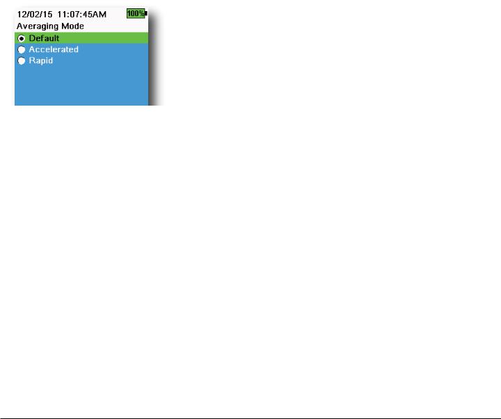
Averaging
 → Averaging (Figure 33)
The averaging mode determines how the handheld will filter data. A smaller time frame for the rolling average window allows changes in the sensor’s measurements to be more quickly observed, while a larger rolling window provides more stable measurement readings and a smooth result. Each averaging mode will decrease the time span of the
Figure 33 Averaging rolling window if a large change in the sensor measurement is detected, allowing the handheld to adapt when an event occurs.
The Default mode provides optimum averaging for all sensors. This mode has up to 40 seconds of averaging on the sensors to curb spikes and outliers, resulting in more stable data.
In Accelerated mode, changes in sensor measurements are more quickly observed than default (approximately 10 seconds of averaging). This mode is recommended when the sensors are moving through the water, such as during profiling studies and most spot sampling applications.
NOTE: For profiling applications, enable Vertical Position under Depth Display to view unfiltered depth measurements. This helps to ensure the depth sensor is lowered to the desired depth without waiting for the averaged measurement.
In Rapid mode, sensor response is very fast (approximately 2 seconds of averaging), but the instrument will never settle on a single steady number. This mode is recommended when the sensors are moving quickly through the water, such as rapid profiling and towed applications.
Operation |
23 |
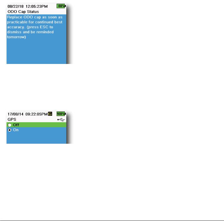
Figure 34 ODO Cap Status
Figure 35 GPS
Salinity
 → Salinity
Salinity is determined by calculations derived from the conductivity and temperature sensors.
When a conductivity sensor is installed, the instrument will automatically use the salinity measurement for DO and “As Measured” will be displayed. If no conductivity sensor is installed (e.g. ODO/T cable assembly used), the salinity value will be user-selectable.
ODO Cap Prompt
 → ODO Cap Prompt
The handheld can remind users when it is time to replace the ODO Cap based on a user-defined interval (Figure 34). To set the reminder, select ODO Cap Prompt and input a number in months. YSI recommends enabling this setting to match the warranty period of the ODO Cap:
•ProDSS ODO Sensor Cap [SKU: 626890] = 12 months
•ODO Extended Warranty Sensor Cap [SKU: 627180] = 24 months
The handheld will automatically recognize the last time the ODO Sensor Cap coefficients were updated and alert the user when the Cap is due for replacement. To disable the prompt, simply enter 0 for the number of months.
GPS (Optional)
 → GPS
→ GPS
Some handhelds feature a built-in GPS. GPS turns the handheld Global
Positioning System On or Off. The  symbol is shown when a GPS signal is received (Figure 35).
When enabled, the GPS coordinates will be saved with the Calibration Record and logged data. Note that the battery will drain more rapidly when GPS is enabled than when it is not enabled.
NOTE: GPS data will be most accurate when there is a clear line of sight to satellites. It may be difficult for the handheld to receive a good GPS signal when under canopy or indoors.
24 |
Operation |
 Loading...